LS T676, LA T676, LO T676, LY T676 Hyper TOPLED® Hyper-Bright ...
LS T676, LA T676, LO T676, LY T676 Hyper TOPLED® Hyper-Bright ...
LS T676, LA T676, LO T676, LY T676 Hyper TOPLED® Hyper-Bright ...

Create successful ePaper yourself
Turn your PDF publications into a flip-book with our unique Google optimized e-Paper software.
<strong>Hyper</strong> TOPLED ®<strong>Hyper</strong>-<strong>Bright</strong> LEDLead (Pb) Free Product - RoHS Compliant<strong>LS</strong> <strong>T676</strong>, <strong>LA</strong> <strong>T676</strong>, <strong>LO</strong> <strong>T676</strong>, <strong>LY</strong> <strong>T676</strong>Besondere Merkmale• Gehäusetyp: weißes P-LCC-2 Gehäuse, farbloserklarer Verguss• Besonderheit des Bauteils: extrem breiteAbstrahlcharakteristik; ideal für Hinterleuchtungenund Einkopplungen in Lichtleiter• Wellenlänge: 633 nm (super-rot),615 nm (amber), 606 nm (orange), 587 nm (gelb)• Abstrahlwinkel: Lambertscher Strahler (120°)• Technologie: InGaAlP• optischer Wirkungsgrad: 11 lm/W (gelb, orange,amber), 7 lm/W (super-rot)• Gruppierungsparameter: Lichtstärke,Wellenlänge• Verarbeitungsmethode: für alleSMT-Bestücktechniken geeignet• Lötmethode: IR Reflow Löten undWellenlöten (TTW)• Vorbehandlung: nach JEDEC Level 2• Gurtung: 8-mm Gurt mit 2000/Rolle, ø180 mmoder 8000/Rolle, ø330 mm• ESD-Festigkeit: ESD-sicher bis 2 kV nachJESD22-A114-BAnwendungen• Informationsanzeigen im Innen- und Außenbereich(z. B. im Verkehrsbereich; Laufschriftanzeigen)• optischer Indikator• Einkopplung in Lichtleiter• Hinterleuchtung (LCD, Handy, Schalter, Tasten,Displays, Werbebeleuchtung)• Innenbeleuchtung im Automobilbereich (z. B.Instrumentenbeleuchtung)• Ersatz von Kleinst-Glühlampen• Signal- und SymbolleuchtenFeatures• package: white P-LCC-2 package, colorless clearresin• feature of the device: extremely wide viewingangle; ideal for backlighting and coupling in lightguides• wavelength: 633 nm (super-red),615 nm (amber), 606 nm (orange),587 nm (yellow)• viewing angle: Lambertian Emitter (120°)• technology: InGaAlP• optical efficiency: 11 lm/W (yellow, orange,amber), 7 lm/W (super-red)• grouping parameter: luminous intensity,wavelength• assembly methods: suitable for allSMT assembly methods• soldering methods: IR reflow soldering andTTW soldering• preconditioning: acc. to JEDEC Level 2• taping: 8 mm tape with 2000/reel, ø180 mm or8000/reel, ø330 mm• ESD-withstand voltage: up to 2 kV acc. toJESD22-A114-BApplications• indoor and outdoor displays (e.g. displays fortraffic; light writing displays)• optical indicators• coupling into light guides• backlighting (LCD, cellular phones, switches, keys,displays, illuminated advertising)• interior automotive lighting(e.g. dashboard backlighting)• substitution of micro incandescent lamps• signal and symbol luminaire2004-08-16 1
<strong>LS</strong> <strong>T676</strong>, <strong>LA</strong> <strong>T676</strong>, <strong>LO</strong> <strong>T676</strong>, <strong>LY</strong> <strong>T676</strong>BestellinformationOrdering InformationTypEmissionsfarbe1) Seite 15Lichtstärke2) Seite 15LichtstromBestellnummerTypeColor ofEmissionLuminous1) page 15IntensityLuminous2) page 15FluxOrdering CodeI F = 20 mAI V (mcd)I F = 20 mAΦ V (mlm)<strong>LS</strong> <strong>T676</strong>-Q1R2-1<strong>LS</strong> <strong>T676</strong>-R1S1-1<strong>LS</strong> <strong>T676</strong>-P2S1-1super-red 71 ... 180112 ... 22456 ... 224380 (typ.)480 (typ.)420 (typ.)Q65110A2151Q65110A2152Q65110A2153<strong>LA</strong> <strong>T676</strong>-R1S2-1<strong>LA</strong> <strong>T676</strong>-S1T1-1<strong>LA</strong> <strong>T676</strong>-Q2T1-1amber 112 ... 280180 ... 35590 ... 355600 (typ.)760 (typ.)665 (typ.)Q65110A2145Q65110A2146Q65110A2147<strong>LO</strong> <strong>T676</strong>-R1S2-24<strong>LO</strong> <strong>T676</strong>-S1T1-24<strong>LO</strong> <strong>T676</strong>-Q2T1-24orange 112 ... 280180 ... 35590 ... 355600 (typ.)760 (typ.)665 (typ.)Q65110A2148Q65110A2149Q65110A2150<strong>LY</strong> <strong>T676</strong>-R1S2-26<strong>LY</strong> <strong>T676</strong>-S1T1-26<strong>LY</strong> <strong>T676</strong>-Q2T1-26yellow 112 ... 280180 ... 35590 ... 355600 (typ.)760 (typ.)665 (typ.)Q65110A2154Q65110A2155Q65110A2156Anm.:Die oben genannten Typbezeichnungen umfassen die bestellbaren Selektionen. Diese bestehen aus wenigenHelligkeitsgruppen (siehe Seite 5 für nähere Informationen). Es wird nur eine einzige Helligkeitsgruppe proGurt geliefert. Z.B.: <strong>LO</strong> <strong>T676</strong>-R1S2-24 bedeutet, dass auf dem Gurt nur eine der Helligkeitsgruppen R1, R2,S1 oder S2 enthalten ist.Um die Liefersicherheit zu gewährleisten, können einzelne Helligkeitsgruppen nicht bestellt werden.Gleiches gilt für die Farben, bei denen Wellenlängengruppen gemessen und gruppiert werden. Pro Gurt wirdnur eine Wellenlängengruppe geliefert. Z.B.: <strong>LO</strong> <strong>T676</strong>-R1S2-24 bedeutet, dass auf dem Gurt nur eine derWellenlängengruppen -2, -3, oder -4 enthalten ist (siehe Seite 5 für nähere Information). <strong>LA</strong> <strong>T676</strong>-R1S2-1bedeutet, dass das Bauteil innerhalb der auf Seite 4 spezifizierten Grenzen geliefert wird.Um die Liefersicherheit zu gewährleisten, können einzelne Wellenlängengruppen nicht bestellt werden.Note: The above Type Numbers represent the order groups which include only a few brightness groups (see page 5for explanation). Only one group will be shipped on each reel (there will be no mixing of two groups on eachreel). E.g. <strong>LO</strong> <strong>T676</strong>-R1S2-24 means that only one group R1, R2, S1 or S2 will be shippable for any one reel.In order to ensure availability, single brightness groups will not be orderable.In a similar manner for colors where wavelength groups are measured and binned, single wavelength groupswill be shipped on any one reel. E.g. <strong>LO</strong> <strong>T676</strong>-R1S2-24 means that only 1 wavelength group -2, -3, or -4 willbe shippable (see page 5 for explanation). <strong>LA</strong> <strong>T676</strong>-R1S2-1 means that the device will be shiped within thespecified limits as stated on page 4.In order to ensure availability, single wavelength groups will not be orderable.2004-08-16 2
<strong>LS</strong> <strong>T676</strong>, <strong>LA</strong> <strong>T676</strong>, <strong>LO</strong> <strong>T676</strong>, <strong>LY</strong> <strong>T676</strong>GrenzwerteMaximum RatingsBezeichnungParameterBetriebstemperaturOperating temperature rangeLagertemperaturStorage temperature rangeSperrschichttemperaturJunction temperatureDurchlassstromForward current(T A =25°C)StoßstromSurge currentt ≤ 10 µs, D = 0.005, T A =25°C3) Seite 15SperrspannungReverse voltage(T A =25°C)3) page 15LeistungsaufnahmePower consumption(T A =25°C)WärmewiderstandThermal resistanceSperrschicht/Umgebung4) page 15Junction/ambientSperrschicht/LötpadJunction/solder point4) Seite 15SymbolSymbol<strong>LS</strong>, <strong>LO</strong>, <strong>LA</strong>WerteValues<strong>LY</strong>T op – 40 … + 100 °CT stg – 40 … + 100 °CT j + 125 °CI F 30 mAI FM 1 0.2 AV R 12 VEinheitUnitP tot 80 mWR th JA500R th JS 280K/WK/W2004-08-16 3
<strong>LS</strong> <strong>T676</strong>, <strong>LA</strong> <strong>T676</strong>, <strong>LO</strong> <strong>T676</strong>, <strong>LY</strong> <strong>T676</strong>KennwerteCharacteristics(T A = 25 °C)BezeichnungParameterWellenlänge des emittierten LichtesWavelength at peak emissionI F = 20 mA5) Seite 15Dominantwellenlänge5) page 15Dominant wavelengthI F = 20 mASpektrale Bandbreite bei 50 % I rel maxSpectral bandwidth at 50 % I rel maxI F = 20 mA(typ.)(typ.)SymbolSymbolWerteValues<strong>LS</strong> <strong>LA</strong> <strong>LO</strong> <strong>LY</strong>λ peak 645 622 610 591 nmλ dom 633± 6615± 6606*+3/–6587*+8/–7EinheitUnitnm∆λ 16 16 16 15 nmAbstrahlwinkel bei 50 % I V (Vollwinkel) (typ.) 2ϕ 120 120 120 120 GradViewing angle at 50 % I V deg.6) Seite 15Durchlassspannung (min.)6) page 15Forward voltage (typ.)I F = 20 mA(max.)Sperrstrom (typ.)Reverse current (max.)V R = 12 VTemperaturkoeffizient von λ peakTemperature coefficient of λ peakI F = 20 mA; –10°C ≤ T ≤ 100°CTemperaturkoeffizient von λ domTemperature coefficient of λ domI F = 20 mA; –10°C ≤ T ≤ 100°CTemperaturkoeffizient von V FTemperature coefficient of V FI F = 20 mA; –10°C ≤ T ≤ 100°COptischer WirkungsgradOptical efficiencyI F = 20 mA* Einzelgruppen siehe Seite 5Individual groups on page 5(typ.)(typ.)(typ.)(typ.)1.8V FV F 2.3V F 2.0I R 0.01I R 101.832.02.330.01101.852.02.350.01101.92.02.40.0110VVVµAµATC λpeak 0.14 0.13 0.13 0.13 nm/KTC λdom 0.05 0.06 0.07 0.10 nm/KTC V– 2.0 – 1.8 – 1.7 – 2.5 mV/Kη opt 7 11 11 11 lm/W2004-08-16 4
<strong>LS</strong> <strong>T676</strong>, <strong>LA</strong> <strong>T676</strong>, <strong>LO</strong> <strong>T676</strong>, <strong>LY</strong> <strong>T676</strong>5) Seite 15Wellenlängengruppen (Dominantwellenlänge)5) page 15Wavelength Groups (Dominant Wavelength)GruppeGroupyellow orange Einheitmin. max. min. max.Unit2 580 583 600 603 nm3 583 586 603 606 nm4 586 589 606 609 nm5 589 592 nm6 592 595 nmHelligkeits-Gruppierungsschema<strong>Bright</strong>ness GroupsHelligkeitsgruppe<strong>Bright</strong>ness GroupP2Q1Q2R1R2S1S2T11) Seite 15LichtstärkeLuminous IntensityI V (mcd)56 ... 7171 ... 9090 ... 112112 ... 140140 ... 180180 ... 224224 ... 280280 ... 3551) page 152) Seite 15LichtstromLuminous FluxΦ V (mlm)190 (typ.)240 (typ.)300 (typ.)380 (typ.)480 (typ.)600 (typ.)760 (typ.)950 (typ.)2) page 15Anm.: Die Standardlieferform von Serientypen beinhaltet entweder eine untere Familiengruppe, eineobere Familiengruppe oder eine Sammelgruppe, die aus nur3 bzw. 4 bzw. 6 Helligkeitsgruppen bestehen.Einzelne Helligkeitsgruppen können nicht bestellt werden.Note: The standard shipping format for serial types includes either a lower family group, an upperfamily group or a grouping of all individual brightness groups of 3 or 4 or 6 individual brightnessgroups.Individual brightness groups cannot be ordered.Gruppenbezeichnung auf EtikettGroup Name on LabelBeispiel: R1-3Example: R1-3Helligkeitsgruppe<strong>Bright</strong>ness GroupR1 3WellenlängeWavelengthAnm.: In einer Verpackungseinheit / Gurt ist immer nur eine Gruppe für jede Selektion enthalten.Note: No packing unit / tape ever contains more than one group for each selection.2004-08-16 5
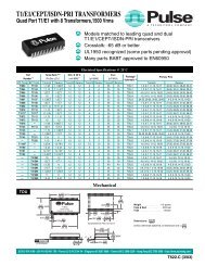
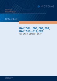
<strong>LS</strong> <strong>T676</strong>, <strong>LA</strong> <strong>T676</strong>, <strong>LO</strong> <strong>T676</strong>, <strong>LY</strong> <strong>T676</strong>2) Seite 15Relative spektrale Emission2) page 15Relative Spectral EmissionV(λ) = spektrale Augenempfindlichkeit / Standard eye response curveI rel = f (λ); T A = 25 °C; I F = 20 mA100OHL00235I rel%80V λ6040yelloworangeambersuper-red2004002) Seite 15AbstrahlcharakteristikRadiation CharacteristicI rel = f (ϕ); T A = 25 °C450 500 550 600 650 nm 700λ2) page 1540˚ 30˚ 20˚ 10˚ 0˚OHL01660ϕ1.050˚0.860˚70˚80˚90˚0.60.40.20100˚1.0 0.8 0.6 0.40˚ 20˚ 40˚ 60˚ 80˚ 100˚ 120˚2004-08-16 6
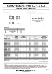
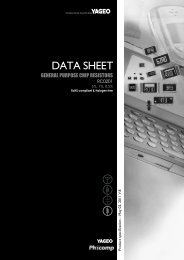
<strong>LS</strong> <strong>T676</strong>, <strong>LA</strong> <strong>T676</strong>, <strong>LO</strong> <strong>T676</strong>, <strong>LY</strong> <strong>T676</strong>2) Seite 15Durchlassstrom2) page 15Forward CurrentI F = f (V F ); T A = 25 °C10 2mA5OHL002322) 7) Seite 15Relative LichtstärkeRelative Luminous IntensityI V /I V(20 mA) = f (I F ); T A = 25 °C10 1I V (20 mA)2) 7) page 15OHL10233I V0I F110510 0010510 -1 super-redyelloworange/amber10 -1 1 1.4 1.8 2.2 2.6 3 V 3.4Maximal zulässiger DurchlassstromMax. Permissible Forward CurrentI F = f (T)I F35mA302520V FOHL01031T AT S10 -2102) Seite 15Relative LichtstärkeRelative Luminous IntensityI V /I V(25 °C) = f (T j ); I F = 20 mAI VI V (25 ˚C)2.01.61.2110 mA 10 2Iorangeyellowambersuper-redF2) page 15OHL00238150.8105T temp. ambienttemp. solder pointAT S0.4orangeyellowambersuper-red0 0 20 40 60 80 ˚C 100T0-20 0 20 40 60 ˚C 100Tj2004-08-16 7
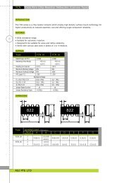
<strong>LS</strong> <strong>T676</strong>, <strong>LA</strong> <strong>T676</strong>, <strong>LO</strong> <strong>T676</strong>, <strong>LY</strong> <strong>T676</strong>Zulässige Impulsbelastbarkeit I F = f (t p )Permissible Pulse Handling CapabilityDuty cycle D = parameter, T A = 25 °C<strong>LS</strong>, <strong>LA</strong>, <strong>LO</strong>I F10A50-1105D =0.0050.010.020.050.10.20.5OHL00318Zulässige Impulsbelastbarkeit I F = f (t p )Permissible Pulse Handling CapabilityDuty cycle D = parameter, T A = 85 °C<strong>LS</strong>, <strong>LA</strong>, <strong>LO</strong>I F10A510 -150ttD = P TPTOHL01427I FD =0.0050.010.020.050.10.20.5-2ttD = P T1010 10P-5 -4 -310 10 -2 10 -1 10 0 10 1 s 10 2Zulässige Impulsbelastbarkeit I F = f (t p )Permissible Pulse Handling CapabilityDuty cycle D = parameter, T A = 25 °C<strong>LY</strong>I F10A50TttD = P TPI FTt pOHL00316I F10 -2-5 -4 -310 1010 10 -2 10 -1 10 0 10 1 s 10 2Zulässige Impulsbelastbarkeit I F = f (t p )Permissible Pulse Handling CapabilityDuty cycle D = parameter, T A = 85 °C<strong>LY</strong>I F10A50ttD = P TPTt pOHL01432I F-1105D =0.0050.010.020.050.10.20.510 -15D =0.0050.010.020.050.10.20.5-21010 10-5 -4 -310 10 -2 10 -1 10 0 10 1 s 10 2t p10 -2-5 -4 -310 1010 10 -2 10 -1 10 0 10 1 s 10 2t p2004-08-16 8
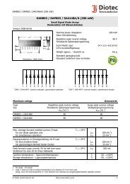
<strong>LS</strong> <strong>T676</strong>, <strong>LA</strong> <strong>T676</strong>, <strong>LO</strong> <strong>T676</strong>, <strong>LY</strong> <strong>T676</strong>8) Seite 15Maßzeichnung8) page 15Package Outlines3.0 (0.118)2.6 (0.102)2.3 (0.091)2.1 (0.083)0.1 (0.004) (typ.)2.1 (0.083)1.7 (0.067)0.9 (0.035)0.7 (0.028)4˚±1A3.4 (0.134)3.0 (0.118)Cathode marking(2.4) (0.095)3.7 (0.146)1.1 (0.043) 3.3 (0.130)0.5 (0.020)0.18 (0.007)0.12 (0.005)0.6 (0.024)0.4 (0.016)CGP<strong>LY</strong>6724Kathodenkennung:Cathode mark:Gewicht / Approx. weight:abgeschrägte Eckebevelled edge35 mg8) Seite 15Gurtung / Polarität und Lage Verpackungseinheit8) page 15Method of Taping / Polarity and Orientation Packing2000/Rolle, ø180 mmoder 8000/Rolle, ø330 mmunit 2000/reel, ø180 mmor 8000/reel, ø330 mm1.5 (0.059)4 (0.157)2 (0.079) Cathode/Collector Marking2.9 (0.114)4 (0.157)3.6 (0.142)3.5 (0.138)1.75 (0.069)8 (0.315)OHAY22712004-08-16 9
_ 16 mmCu-area > 16 mm 2OHLPY970Empfohlenes Lötpaddesign verwendbar für TOPLED ® und Power TOPLED ®8) Seite 15IR Reflow LötenRecommended Solder Pad useable for TOPLED ® and Power TOPLED ®8) page 15IR Reflow SolderingPadgeometrie fürverbesserte WärmeableitungPaddesign forimproved heat dissipationAnode3.3 (0.130)Fläche darf elektrisch nicht beschaltet werden.Do not use this area for electrical contact.3.3 (0.130)2.3 (0.091)0.8 (0.031)3.7 (0.146)1.1 (0.043)1.5 (0.059)11.1 (0.437)0.7 (0.028)Kathode/CathodeFläche darf elektrisch nicht beschaltet werden.Do not use this area for electrical contact.Cu Fläche /Cu-area16 mm 2 per padLötstoplackSolder resistOHLPY4402004-08-16 10
<strong>LS</strong> <strong>T676</strong>, <strong>LA</strong> <strong>T676</strong>, <strong>LO</strong> <strong>T676</strong>, <strong>LY</strong> <strong>T676</strong>Lötbedingungen Vorbehandlung nach JEDEC Level 2Soldering Conditions Preconditioning acc. to JEDEC Level 2IR-Reflow Lötprofil für bleifreies LötenIR Reflow Soldering Profile for lead free soldering(nach J-STD-020B)(acc. to J-STD-020B)T300˚C250200255 ˚C240 ˚C217 ˚CMaximum Solder ProfileRecommended Solder ProfileMinimum Solder Profile30 s max10 s minOH<strong>LA</strong>0687+0 ˚C260 ˚C -5 ˚C245 ˚C ±5 ˚C+5 ˚C235 ˚C -0 ˚C150100120 s maxRamp Down6 K/s (max)100 s max5000Ramp Up3 K/s (max)25 ˚C50 100 150 200 250 s 300tWellenlöten (TTW) (nach CECC 00802)TTW Soldering (acc. to CECC 00802)T300C250200235 C ... 260C1. Welle1. wave10 s2. Welle2. waveNormalkurvestandard curveGrenzkurvenlimit curvesOH<strong>LY</strong>0598150100100C ... 130Cca 200 K/s5 K/s2 K/s502 K/sZwangskühlungforced cooling0050 100 150 200 s 250t2004-08-16 11
<strong>LS</strong> <strong>T676</strong>, <strong>LA</strong> <strong>T676</strong>, <strong>LO</strong> <strong>T676</strong>, <strong>LY</strong> <strong>T676</strong>Barcode-Produkt-Etikett (BPL)Barcode-Product-Label (BPL)GurtverpackungTape and ReelOSRAM OptoSemiconductors(6P) BATCH NO: Batch NumberBar Code(1T) <strong>LO</strong>T NO: Lot NumberBar Code(X) PROD NO: Product Code(9D) D/C: Date Code(Q)QTY: Product Quantity per Reel(G) GROUP: X - X - XSampleBar CodeLx xxxxProduct NameRoHS Compliant ML2Bin1: Bin Information Color 1Bin2:Bin3:Temp ST260 C RTAdditional TEXTR077DEMYPACKVAR: Packing TypeForward Voltage GroupWavelength Group<strong>Bright</strong>ness GroupOHA12043D 0P2P 1P 0Direction of unreelingW 1W 2Direction of unreelingF EWAN13.0±0.25LabelGurtvorlauf:Leader:Gurtende:Trailer:400 mm400 mm160 mm160 mmOHAY0324Tape dimensions in mm (inch)W P 0 P 1 P 2 D 0 E F8 + 0.3– 0.14 ± 0.1(0.157 ± 0.004)4 ± 0.1(0.157 ± 0.004)2 ± 0.05(0.079 ± 0.002)1.5 + 0.1(0.059 + 0.004)1.75 ± 0.1(0.069 ± 0.004)3.5 ± 0.05(0.138 ± 0.002)Reel dimensions in mm (inch)A W N min W 1 W 2 max180 (7) 8 (0.315) 60 (2.362) 8.4 + 2 (0.331 + 0.079) 14.4 (0.567)330 (13) 8 (0.315) 60 (2.362) 8.4 + 2 (0.331 + 0.079) 14.4 (0.567)2004-08-16 12
_ Year Moisture Level 4 Floor time 72 HoursMoisture Level 2 Floor time 1 Year Moisture Level 5 Floor time 48 HoursMoisture Level 2a Floor time 4 Weeks Moisture Level 5a Floor time 24 HoursMoisture Level 3 Floor time 168 Hours Moisture Level 6 Floor time 6 HoursIf blank, s ebar code labelOSRAM OptoSemiconductors(6P) BATCH NO:(1T) <strong>LO</strong>T NO:21 021 98123GH1234Muster(X) PROD NO: 10 425 (Q)QTY: 2 0<strong>LS</strong>Y <strong>T676</strong>Multi TOPLEDBin1: P-1-20Bin2: Q-1-2020 C R240 C R3 260 C RTA ditional TEXTR0 7PACKVAR:(G) GROUP:P-1+Q-1Barcode labelOSRAM OptoSemiconductors(6P) BATCH NO:(1T) <strong>LO</strong>T NO:21 021 98123GH1234Muster(X) PROD NO: 1<strong>LS</strong>Y <strong>T676</strong>Multi TOPLED0 425 (Q)QTY: 2 0Bin1: P-1-20Bin2: Q-1-2020 C R240 C R3 260 C RTA ditional TEXT(G) GROUP:P-1+Q-1OSRAMPackingSealing labelOHA020442004-08-16 13
<strong>LS</strong> <strong>T676</strong>, <strong>LA</strong> <strong>T676</strong>, <strong>LO</strong> <strong>T676</strong>, <strong>LY</strong> <strong>T676</strong>Revision History: 2007-03-01Previous Version:Page Subjects (major changes since last revision) Date of changeAttention please!The information describes the type of component and shall not be considered as assured characteristics.Terms of delivery and rights to change design reserved. Due to technical requirements components may containdangerous substances. For information on the types in question please contact our Sales Organization.If printed or downloaded, please find the latest version in the Internet.PackingPlease use the recycling operators known to you. We can also help you – get in touch with your nearest sales office.By agreement we will take packing material back, if it is sorted. You must bear the costs of transport. For packingmaterial that is returned to us unsorted or which we are not obliged to accept, we shall have to invoice you for any costsincurred.Components used in life-support devices or systems must be expressly authorized for such purpose! Criticalcomponents 10) page 15 may only be used in life-support devices or systems 11) page 15 with the express written approval ofOSRAM OS.2004-08-16 14
<strong>LS</strong> <strong>T676</strong>, <strong>LA</strong> <strong>T676</strong>, <strong>LO</strong> <strong>T676</strong>, <strong>LY</strong> <strong>T676</strong>Fußnoten:1)Helligkeitswerte werden mit einer Stromeinprägedauervon 25 ms und einer Genauigkeit von± 11% ermittelt.2)Wegen der besonderen Prozessbedingungen bei derHerstellung von LED können typische oder abgeleitetetechnische Parameter nur aufgrund statistischerWerte wiedergegeben werden. Diese stimmen nichtnotwendigerweise mit den Werten jedes einzelnenProduktes überein, dessen Werte sich von typischenund abgeleiteten Werten oder typischen Kennlinienunterscheiden können. Falls erforderlich, z.B.aufgrund technischer Verbesserungen, werden diesetypischen Werte ohne weitere Ankündigung geändert.3)Die LED kann kurzzeitig in Sperrichtung betriebenwerden.4)R thJA ergibt sich bei Montage auf PC-Board FR 4(Padgröße ≥ 16 mm 2 je Pad)5)Wellenlängen werden mit einer Stromeinprägedauervon 25 ms und einer Genauigkeit von ±1 nm ermittelt.6)Spannungswerte werden mit einerStromeinprägedauer von 1 ms und einer Genauigkeitvon ±0,1 V ermittelt.7)Im gestrichelten Bereich der Kennlinien muss miterhöhten Helligkeitsunterschieden zwischenLeuchtdioden innerhalb einer Verpackungseinheitgerechnet werden8)Maße werden wie folgt angegeben: mm (inch)9)Gehäuse für Wellenlöten (TTW) geeignet10)Ein kritisches Bauteil ist ein Bauteil, das inlebenserhaltenden Apparaten oder Systemeneingesetzt wird und dessen Defekt voraussichtlich zueiner Fehlfunktion dieses lebenserhaltendenApparates oder Systems führen wird oder dieSicherheit oder Effektivität dieses Apparates oderSystems beeinträchtigt.11)Lebenserhaltende Apparate oder Systeme sind für(a) die Implantierung in den menschlichen Körperoder(b) für die Lebenserhaltung bestimmt.Falls sie versagen, kann davon ausgegangen werden,dass die Gesundheit und das Leben des Patienten inGefahr ist.Remarks:1)<strong>Bright</strong>ness groups are tested at a current pulseduration of 25 ms and a tolerance of ± 11%.2)Due to the special conditions of the manufacturingprocesses of LED, the typical data or calculatedcorrelations of technical parameters can only reflectstatistical figures. These do not necessarilycorrespond to the actual parameters of each singleproduct, which could differ from the typical data andcalculated correlations or the typical characteristicline. If requested, e.g. because of technicalimprovements, these typ. data will be changed withoutany further notice.3)Driving the LED in reverse direction is suitable forshort term application.4)R thJA results from mounting on PC board FR 4(pad size ≥ 16 mm 2 per pad)5)Wavelengths are tested at a current pulse duration of25 ms and a tolerance of ±1 nm.6)Forward voltages are tested at a current pulseduration of 1 ms and a tolerance of ±0.1 V.7)In the range where the line of the graph is broken, youmust expect higher brightness differences betweensingle LEDs within one packing unit.8)Dimensions are specified as follows: mm (inch)9)Package suitable for TTW-soldering10)A critical component is a component used in alife-support device or system whose failure canreasonably be expected to cause the failure of thatlife-support device or system, or to affect its safety orthe effectiveness of that device or system.11)Life support devices or systems are intended(a) to be implanted in the human body,or(b) to support and/or maintain and sustain human life.If they fail, it is reasonable to assume that the healthand the life of the user may be endangered.Published byOSRAM Opto Semiconductors GmbHWernerwerkstrasse 2, D-93049 Regensburgwww.osram-os.com© All Rights Reserved.2004-08-16 15