SD-RP-AI-0625_1_GG Final Report.pdf - âGalileo Galileiâ (GG
SD-RP-AI-0625_1_GG Final Report.pdf - âGalileo Galileiâ (GG
SD-RP-AI-0625_1_GG Final Report.pdf - âGalileo Galileiâ (GG

Create successful ePaper yourself
Turn your PDF publications into a flip-book with our unique Google optimized e-Paper software.
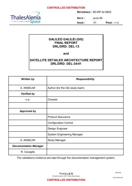
CONTROLLED DISTRIBUTIONREFERENCE :<strong>SD</strong>-<strong>RP</strong>-<strong>AI</strong>-<strong>0625</strong>DATE :June 09ISSUE : 01 PAGE : 1/172GALILEO GALILEI (<strong>GG</strong>)FINAL REPORTDRL/DRD: DEL-13andSATELLITE DET<strong>AI</strong>LED ARCHITECTURE REPORTDRL/DRD: DEL-34/41Written byResponsibilityA. ANSELMI Author (for the <strong>GG</strong> study team)Verified byn.a.CheckerApproved byProduct AssuranceConfiguration ControlDesign EngineerSystem Engineering ManagerA. ANSELMI Study ManagerDocumentation ManagerR. CavagliàThe validations evidence are kept through the documentation management system.M032-ENAll rights reserved, 2007, Thales Alenia SpaceCONTROLLED DISTRIBUTION100181547K-EN
CONTROLLED DISTRIBUTIONREFERENCE :<strong>SD</strong>-<strong>RP</strong>-<strong>AI</strong>-<strong>0625</strong>DATE :June 09ISSUE : 01 PAGE : 2/172ISSUE DATE § CHANGE RECORDS AUTHOR01 8-Jun-09 First issue submitted to PRRM032-ENAll rights reserved, 2009, Thales Alenia SpaceCONTROLLED DISTRIBUTION100181547K-EN
CONTROLLED DISTRIBUTIONREFERENCE :<strong>SD</strong>-<strong>RP</strong>-<strong>AI</strong>-<strong>0625</strong>DATE :June 09ISSUE : 01 PAGE : 3/172TABLE OF CONTENTS1. SCOPE AND PU<strong>RP</strong>OSE ................................................................................................102. REFERENCES ...............................................................................................................112.1 Applicable Documents ................................................................................................................. 112.2 Standards ..................................................................................................................................... 112.3 ASI Reference Documents............................................................................................................ 112.4 <strong>GG</strong> Phase A2 Study Notes ............................................................................................................ 112.5 External Reference Documents ....................................................................................................123. MISSION AND EXPERIMENT SUMMARY......................................................................134. PAYLOAD DESCRIPTION .............................................................................................144.1 Payload Main Elements ................................................................................................................ 144.2 Lock/Unlock Mechanisms............................................................................................................. 194.2.1 Locking devices - Acceleration loads evaluation ........................................................................... 204.2.2 Design of the locking mechanisms. Locking of the test masses...................................................... 214.2.3 Locking of the inner differential measuring devices ....................................................................... 234.2.4 Dynamic behaviour of the differential measuring device ................................................................ 284.3 Thermal Stabilization and Co-Rotation ......................................................................................... 314.4 Test mass materials...................................................................................................................... 335. SATELLITE, ORBIT AND THE VEGA LAUNCHER ........................................................375.1 Launcher and mission .................................................................................................................. 375.2 Satellite mechanical configuration ............................................................................................... 415.2.1 <strong>GG</strong> configuration description ....................................................................................................... 415.2.2 <strong>GG</strong> spacecraft mechanical design and FEM model....................................................................... 485.3 Thermal design and analysis........................................................................................................ 525.3.1 TCS requirements ...................................................................................................................... 525.3.2 TCS description.......................................................................................................................... 525.3.3 Mathematical model description................................................................................................... 535.3.4 Analysis results .......................................................................................................................... 585.3.5 Conclusions ............................................................................................................................... 625.4 Electrical Architecture.................................................................................................................. 635.5 On-board data handling design .................................................................................................... 65M032-ENAll rights reserved, 2009, Thales Alenia SpaceCONTROLLED DISTRIBUTION100181547K-EN
CONTROLLED DISTRIBUTIONREFERENCE :<strong>SD</strong>-<strong>RP</strong>-<strong>AI</strong>-<strong>0625</strong>DATE :June 09ISSUE : 01 PAGE : 5/1727.3.3 Common mode motion of the test masses.................................................................................. 1447.3.4 Differential mode motion of the test masses ............................................................................... 1487.3.5 Dynamic range of the simulator ................................................................................................. 1507.4 Conclusions ............................................................................................................................... 1518. THE GROUND SEGMENT............................................................................................ 1528.1 Key <strong>GG</strong> Operations Requirements.............................................................................................. 1528.2 Ground Segment Description ..................................................................................................... 1538.3 User Segment Description.......................................................................................................... 1548.4 Science Operations and Science Management Plan................................................................... 1559. DEVELOPMENT APPROACH AND PROGRAMMATICS.............................................. 1589.1 Satellite development approach ................................................................................................. 1589.1.1 Development objectives and elements ....................................................................................... 1589.1.2 Program flow............................................................................................................................ 1599.1.3 Model Philosophy ..................................................................................................................... 1609.1.4 Schedule.................................................................................................................................. 1609.2 Payload development plan ......................................................................................................... 1629.3 Platform development plan......................................................................................................... 1639.4 Development plan for the Ground Segment ............................................................................... 1659.5 Development plan for the User Segment .................................................................................... 1669.6 Program management ................................................................................................................ 1669.7 Milestones and meetings plan.................................................................................................... 1679.7.1 Phase B................................................................................................................................... 1679.7.2 Phase C/D ............................................................................................................................... 1679.7.3 Phase E................................................................................................................................... 1689.7.4 Program milestone summary..................................................................................................... 16810. LIST OF ACRONYMS AND ABBREVIATIONS ......................................................... 170M032-ENAll rights reserved, 2009, Thales Alenia SpaceCONTROLLED DISTRIBUTION100181547K-EN
CONTROLLED DISTRIBUTIONREFERENCE :<strong>SD</strong>-<strong>RP</strong>-<strong>AI</strong>-<strong>0625</strong>DATE :June 09ISSUE : 01 PAGE : 6/172LIST OF FIGURESFigure 4.1-1: Construction details of the springs connecting the PGB to the spacecraft .......................................15Figure 4.1-2: Mechanical properties of the springs designed to connect the PGB to the spacecraft ......................16Figure 4.1-3: Details from the engineering drawings of the <strong>GG</strong> differential accelerometer....................................17Figure 4.1-4: Further details from the engineering drawings of the <strong>GG</strong> differential accelerometer .........................18Figure 4.2-1: Schematics of the fine lock/unlock mechanisms............................................................................19Figure 4.2-2: <strong>GG</strong> spacecraft axes definition......................................................................................................20Figure 4.2-3: Test masses locking concept.......................................................................................................22Figure 4.2-4: Inner differential measuring devices locking concept .....................................................................23Figure 4.2-5: Inner differential measuring devices locking concept (detail)..........................................................24Figure 4.2-6: Inner differential measuring devices locking concept (section 1).....................................................24Figure 4.2-7: Inner differential measuring devices locking concept (section 2).....................................................25Figure 4.2-8: Inner differential measuring device main body ..............................................................................25Figure 4.2-9: Inner differential measuring device main body modification for locking devices accommodation.......26Figure 4.2-10: Inner differential measuring devices locking iso view ...................................................................27Figure 4.2-11: Inner differential measuring devices locking axial view ................................................................27Figure 4.2-12: Differential measuring device locking mechanism - Titanium - First normal mode..........................29Figure 4.2-13: Differential measuring device locking mechanism - Titanium - First “free-free” mode .....................29Figure 4.2-14: Differential measuring device locking mechanism - Light alloy - First normal mode........................30Figure 4.2-15: Differential measuring device locking mechanism - Light alloy - First “free-free” mode...................30Figure 4.4-1: B/µ as function of the atomic number (the red dots have been added to the original plot in [RD 32]). 34Figure 4.4-2: L/µ as function of the atomic number (the red dot has been added to the original plot in [RD 32]).....35Figure 4.4-3 : I Z /µ as function of the atomic number (the red dots have been added to the original plot in [RD 32]) 36Figure 5.1-1: VEGA performance for circular orbits. ..........................................................................................37Figure 5.1-2: NASA forecast of F10.7 solar flux index [June 2008 NASA MSFC bulletin] .....................................39Figure 5.1-3: Parametric analysis of the drag acceleration.................................................................................40Figure 5.2-1: <strong>GG</strong> Spacecraft Configuration.......................................................................................................42Figure 5.2-2: View of <strong>GG</strong> Spacecraft beneath Vega fairing ................................................................................43Figure 5.2-3: View of <strong>GG</strong> Spacecraft (transparent view) ....................................................................................44Figure 5.2-4: <strong>GG</strong> Spacecraft sections beneath fairing (a) and on flight (b) ..........................................................45Figure 5.2-5: <strong>GG</strong> Spacecraft main dimensions..................................................................................................46Figure 5.2-6: <strong>GG</strong> Spacecraft Preliminary Layout ...............................................................................................46Figure 5.2-7: <strong>GG</strong> Experiment mechanical interface concept...............................................................................47Figure 5.2-8: PGB interfaces with <strong>GG</strong> Spacecraft exploded view .......................................................................47Figure 5.2-9: <strong>GG</strong> Spacecraft FEM model used for stiffness verification...............................................................48Figure 5.2-10: <strong>GG</strong> Spacecraft FEM model details .............................................................................................49Figure 5.2-11: <strong>GG</strong> FEM Model first axial eigenfrequency (43.76 Hz) ..................................................................50Figure 5.2-12: <strong>GG</strong> FEM Model first lateral eigenfrequency (24.07 Hz) ................................................................50Figure 5.2-13: <strong>GG</strong> FEM model first solar panels eigenfrequency (92.75 Hz) .......................................................51Figure 5.3-1: Overall <strong>GG</strong> Geometrical Mathematical Model component breakdown.............................................53Figure 5.3-2: Thermal analysis results: typical temperature profiles....................................................................60Figure 5.4-1: <strong>GG</strong> electrical architecture block diagram. .....................................................................................64Figure 5.5-1: Functional block diagram of a generic CDMU based on TAS-I heritage. .........................................66Figure 5.5-2: “Leonardo” CDMU ......................................................................................................................66Figure 5.6-1: Functional block diagram of the proposed PCDU ..........................................................................68Figure 5.6-2: PCDU unit considered for <strong>GG</strong>......................................................................................................71Figure 5.6-3: ‘s-p’ battery cell topology .............................................................................................................72Figure 5.6-4: Battery overcharge protection mechanism....................................................................................72Figure 5.6-5: Proposed solar panel string layout ...............................................................................................75Figure 5.6-6: Solar panel drum configuration ....................................................................................................75Figure 5.6-7: Corrected cosine loss factor ........................................................................................................76Figure 5.6-8: Calculated solar array power (BOL) .............................................................................................78Figure 5.6-9: Calculated solar array power (EOL) .............................................................................................78Figure 5.7-1: <strong>GG</strong> TT&C block diagram .............................................................................................................79Figure 5.7-2: ATV S-Band quadrifilar antenna picture (RIMSA courtesy) ............................................................83M032-ENAll rights reserved, 2009, Thales Alenia SpaceCONTROLLED DISTRIBUTION100181547K-EN
CONTROLLED DISTRIBUTIONREFERENCE :<strong>SD</strong>-<strong>RP</strong>-<strong>AI</strong>-<strong>0625</strong>DATE :June 09ISSUE : 01 PAGE : 7/172Figure 5.7-3: ATV S-Band quadrifilar antenna radiation pattern (RIMSA courtesy) ..............................................84Figure 5.7-4: TT&C interfaces to CDMU CPDU.................................................................................................85Figure 5.7-5: TT&C interfaces to CDMU Encoder and Decoder..........................................................................86Figure 5.7-6: TT&C interfaces to EPS ..............................................................................................................86Figure 5.8-1: <strong>GG</strong> Spacecraft CoG, MoI and PoI budgets ...................................................................................87Figure 6.2-1: DFAC mode organization. ...........................................................................................................96Figure 6.3-1: Force-displacement transfer function in the Inertial Reference Frame.............................................99Figure 6.3-2: Force-displacement transfer function in the Body Reference Frame ............................................. 100Figure 6.3-3: Force-displacement transfer function in the Body Reference Frame (zoom).................................. 100Figure 6.3-4: Linear axis control architecture .................................................................................................. 102Figure 6.3-5: Block diagrams and functions considered for the algorithm design. .............................................. 103Figure 6.3-6: Model embed in the one-axis observer (X , Y and Z axes). .......................................................... 105Figure 6.4-1: ESA missions based on FEEP micro-propulsion. ........................................................................ 107Figure 6.4-2: FEEP cluster assembly for Lisa Pathfinder. ................................................................................ 108Figure 6.4-3: FEEP thrusters resolution.......................................................................................................... 108Figure 6.4-4: Percentage of sparks vs. time between sparks ........................................................................... 109Figure 6.4-5: Spark rate vs. thrust level. ......................................................................................................... 109Figure 6.4-6: Spectral density of the cold gas thrusters noise measured by the Nanobalance facility (TAS-I). ..... 111Figure 6.4-7: Pictures of the major CGPS component. .................................................................................... 112Figure 6.5-1: Spin rate sensor - Internal section view ...................................................................................... 113Figure 6.6-1: Time series of the XY plane perturbing force (inertial reference frame) ......................................... 114Figure 6.6-2: Spectrum of the XY plane perturbing force (inertial reference frame)............................................ 115Figure 6.6-3: Time series of the XY plane perturbing force (body reference frame)............................................ 115Figure 6.6-4: Time evolution of the PGB- spacecraft COMs relative position..................................................... 116Figure 6.6-5: Time evolution of the PGB- spacecraft COMs relative position (zoom).......................................... 117Figure 6.6-6: Phase diagram of the PGB- spacecraft COMs relative position.................................................... 117Figure 6.6-7: Phase diagram of the PGB- spacecraft COMs relative position (zoom)......................................... 118Figure 6.6-8: Time evolution of the PGB- spacecraft COMs relative position (body reference frame) .................. 119Figure 6.6-9: Zoom of the PGB- spacecraft COMs relative position (body reference frame) ............................... 119Figure 6.6-10: One-sided spectral density PGB-spacecraft COMs relative position (body reference frame)......... 120Figure 6.6-11: Zoom around 1Hz of the previous figure................................................................................... 120Figure 6.6-12: Time evolution of the PGB- spacecraft COMs relative position (body reference frame, withoutmeasurement noise) ............................................................................................................................. 121Figure 6.6-13: One-side spectral density PGB- spacecraft COMs relative position (body reference frame, withoutmeasurement noise) ............................................................................................................................. 122Figure 6.6-14: Zoom around 1Hz of the one-side spectral density PGB- spacecraft COMs relative position (bodyreference frame, without measurement noise) ........................................................................................ 122Figure 6.6-15: Zoom around 1Hz of the one-side spectral density PGB- spacecraft COMs relative position (bodyreference frame, without measurement noise) ........................................................................................ 123Figure 6.6-16: Time evolution of the PGB- spacecraft COMs relative position (body reference frame, withmeasurement noise) ............................................................................................................................. 123Figure 6.6-17: Zoom around 1Hz of the one-side spectral density PGB- spacecraft COMs relative position (bodyreference frame, with measurement noise)............................................................................................. 124Figure 7.2-1: <strong>GG</strong> simulator block-diagram. ..................................................................................................... 127Figure 7.2-2: The Inertial Reference Frame is the J2000 Equatorial Reference Frame. ..................................... 129Figure 7.2-3: The Local Vertical Local Horizontal Reference Frame (LVLH)...................................................... 130Figure 7.2-4: Schematic model of the <strong>GG</strong> dynamics system. ........................................................................... 134Figure 7.2-5: Sensor/actuator geometrical imperfections ................................................................................. 136Figure 7.2-6: Block diagram of the white noise shaping technique.................................................................... 137Figure 7.2-7: Time history of the fluctuating component of temperature obtained with the white noise shapingtechnique............................................................................................................................................. 137Figure 7.2-8: Spectral density of the temperature fluctuation computed from the simulated time history vs. theSpectral density desired analytic law...................................................................................................... 138Figure 7.3-1: Scheme of the initial conditions for the satellite orbit of this simulation. ......................................... 141Figure 7.3-2: Time history of the spacecraft non gravitational acceleration along X LVLH ...................................... 142Figure 7.3-3: Time history of the spacecraft non gravitational acceleration along Y LVLH ...................................... 143M032-ENAll rights reserved, 2009, Thales Alenia SpaceCONTROLLED DISTRIBUTION100181547K-EN
CONTROLLED DISTRIBUTIONREFERENCE :<strong>SD</strong>-<strong>RP</strong>-<strong>AI</strong>-<strong>0625</strong>DATE :June 09ISSUE : 01 PAGE : 8/172Figure 7.3-4: Time history of the satellite non gravitational acceleration along Z IRF ............................................ 143Figure 7.3-5: TMe-PGB displacement along the X LVLH axis .............................................................................. 146Figure 7.3-6: TMe-PGB displacement along the Y LVLH axis .............................................................................. 146Figure 7.3-7: TMe-PGB displacement along the Y LVLH axis .............................................................................. 147Figure 7.3-8: Test mass differential displacement w.r.t. the IRF. ...................................................................... 148Figure 7.3-9: Test masses differential displacements in the LVLH frame. .........................................................149Figure 8.2-1: Functional model of the <strong>GG</strong> ground segment. ............................................................................. 153Figure 9.1-1: <strong>GG</strong> program master schedule.................................................................................................... 161Figure 9.2-1: Two-model approach to PGB system testing .............................................................................. 162Figure 9.3-1: Development Plan at satellite level............................................................................................. 164Figure 9.4-1: Ground segment development plan............................................................................................ 165M032-ENAll rights reserved, 2009, Thales Alenia SpaceCONTROLLED DISTRIBUTION100181547K-EN
CONTROLLED DISTRIBUTIONREFERENCE :<strong>SD</strong>-<strong>RP</strong>-<strong>AI</strong>-<strong>0625</strong>DATE :June 09ISSUE : 01 PAGE : 9/172LIST OF TABLESTable 5.1-1: Sequence of events in the <strong>GG</strong> mission..........................................................................................38Table 5.3-1: Radiator areas.............................................................................................................................54Table 5.3-2: Thermo-optical properties.............................................................................................................54Table 5.3-3: Orbit and Attitude properties .........................................................................................................56Table 5.3-4: Materials thermal properties .........................................................................................................57Table 5.3-5: Units power dissipations...............................................................................................................58Table 5.3-6: Analysis cases for sensitivity ........................................................................................................60Table 5.3-7: Comparison of thermal analysis results with the requirements ........................................................61Table 5.6-1: PCDU boards ..............................................................................................................................70Table 5.6-2: Characteristics of the Sony 18650HC Li-Ion cell.............................................................................71Table 5.6-3: Solar cell characteristics...............................................................................................................74Table 5.6-4: By-pass protection diode characteristics........................................................................................74Table 5.7-1: TM data rates with limitation to 512 kbps .......................................................................................80Table 5.7-2: Link budget summary ...................................................................................................................80Table 5.7-3: Transponder RX Characteristics ...................................................................................................82Table 5.7-4: Transponder TX Characteristics....................................................................................................82Table 5.8-1: <strong>GG</strong> Experiment Mass Budget .......................................................................................................88Table 5.8-2: <strong>GG</strong> Spacecraft Subsystems Mass Budget .....................................................................................89Table 5.8-3: <strong>GG</strong> Spacecraft System Mass Budget ............................................................................................90Table 5.8-4: Satellite power budget..................................................................................................................91Table 5.8-5: Satellite data budgets...................................................................................................................92Table 6.2-1: Vega launcher performances [RD 31]............................................................................................94Table 6.2-2: Equipment versus operating mode ................................................................................................97Table 6.4-1: Status of FEEP thrusters with respect to <strong>GG</strong> requirements ........................................................... 107Table 6.4-2: Status of Cold Gas Propulsion System with respect to <strong>GG</strong> requirements ....................................... 111Table 7.2-1: Hinge degrees of freedom .......................................................................................................... 133Table 7.2-2: Oscillation periods ..................................................................................................................... 135Table 7.3-1: Oscillation periods adopted in the simulation ............................................................................... 140Table 8.4-1: Telemetry data rate budget........................................................................................................ 157Table 9.2-1: PGB unit model philosophy ........................................................................................................ 163Table 9.7-1: <strong>GG</strong> program milestones ............................................................................................................ 169M032-ENAll rights reserved, 2009, Thales Alenia SpaceCONTROLLED DISTRIBUTION100181547K-EN
CONTROLLED DISTRIBUTIONREFERENCE :<strong>SD</strong>-<strong>RP</strong>-<strong>AI</strong>-<strong>0625</strong>DATE :June 09ISSUE : 01 PAGE : 10/1721. SCOPE AND PU<strong>RP</strong>OSEThis document is submitted in partial fulfillment of Work Package 1A-AA of the <strong>GG</strong> Phase A2Study. It comprises the <strong>Final</strong> <strong>Report</strong> (DRL item DEL-13) and the Satellite Detailed Architecturereport (DEL-34).The purpose of the document is to provide a comprehensive description of the design adoptedfor the <strong>GG</strong> satellite at the end of the Phase A2 Study. The trade-offs leading to the designdescribed in this document are summarized in a companion report [RD 9].M032-ENAll rights reserved, 2009, Thales Alenia SpaceCONTROLLED DISTRIBUTION100181547K-EN
CONTROLLED DISTRIBUTIONREFERENCE :<strong>SD</strong>-<strong>RP</strong>-<strong>AI</strong>-<strong>0625</strong>DATE :June 09ISSUE : 01 PAGE : 11/1722. REFERENCES2.1 Applicable Documents[AD 1] ASI, “Progetto Galileo Galilei-<strong>GG</strong> Fase A-2, Capitolato Tecnico”, DC-IPC-2007-082, Rev. B,10-10-2007 and applicable documents defined therein2.2 Standards[<strong>SD</strong> 1] ECSS-M-00-02A, Space Project Management – Tailoring of Space Standards, 25 April 2000[<strong>SD</strong> 2] ECSS-E-ST-10C, Space Engineering - System Engineering General Requirements, 6 March2009[<strong>SD</strong> 3] ECSS-E-10-02A, Space Engineering – Verification[<strong>SD</strong> 4] ECSS-Q-00A, Space Product Assurance - Policy and Principles, and related Level 2standards.2.3 ASI Reference Documents[RD 1] <strong>GG</strong> Phase A Study <strong>Report</strong>, Nov. 1998, revised Jan. 2000, available at:http://eotvos.dm.unipi.it/nobili/ggweb/phaseA/index.html[RD 2] Supplement to <strong>GG</strong> Phase A Study (<strong>GG</strong> in sun-synchronous Orbit) “Galileo Galilei-<strong>GG</strong>”: design,requirements, error budget and significance of the ground prototype”, A.M. Nobili et al.,Physics Letters A 318 (2003) 172–183, available at:http://eotvos.dm.unipi.it/nobili/documents/generalpapers/<strong>GG</strong>_PLA2003.<strong>pdf</strong>[RD 3] A. Nobili, DEL001: <strong>GG</strong> Science Requirements, Pisa, September 20082.4 <strong>GG</strong> Phase A2 Study Notes[RD 4] <strong>SD</strong>-<strong>RP</strong>-<strong>AI</strong>-<strong>0625</strong>, <strong>GG</strong> <strong>Final</strong> <strong>Report</strong> / Satellite Detailed Architecture <strong>Report</strong>, Issue 1[RD 5] <strong>SD</strong>-<strong>RP</strong>-<strong>AI</strong>-0626, <strong>GG</strong> Phase A2 Study Executive Summary, Issue 1[RD 6] <strong>SD</strong>-TN-<strong>AI</strong>-1163, <strong>GG</strong> Experiment Concept and Requirements Document, Issue 3[RD 7] <strong>SD</strong>-<strong>RP</strong>-<strong>AI</strong>-0620, <strong>GG</strong> System Performance <strong>Report</strong>, Issue 2[RD 8] <strong>SD</strong>-TN-<strong>AI</strong>-1167, <strong>GG</strong> Mission Requirements Document, Issue 2[RD 9] <strong>SD</strong>-<strong>RP</strong>-<strong>AI</strong>-0590, <strong>GG</strong> System Concept <strong>Report</strong> (Mission Description Document), Issue 3[RD 10] <strong>SD</strong>-SY-<strong>AI</strong>-0014, <strong>GG</strong> System Functional Specification and Preliminary System TechnicalSpecification, Issue 1[RD 11] <strong>SD</strong>-<strong>RP</strong>-<strong>AI</strong>-0631, <strong>GG</strong> Consolidated Mission Description Document, Issue 1[RD 12] <strong>SD</strong>-TN-<strong>AI</strong>-1168, <strong>GG</strong> Mission Analysis <strong>Report</strong>, Issue 2[RD 13] <strong>GG</strong>-TN-DTM-002, Galileo Galilei Satellite - Design & Structural Analysis <strong>Report</strong>, Issue 1M032-ENAll rights reserved, 2009, Thales Alenia SpaceCONTROLLED DISTRIBUTION100181547K-EN
CONTROLLED DISTRIBUTIONREFERENCE :<strong>SD</strong>-<strong>RP</strong>-<strong>AI</strong>-<strong>0625</strong>DATE :June 09ISSUE : 01 PAGE : 12/172[RD 14] <strong>SD</strong>-<strong>RP</strong>-<strong>AI</strong>-0627, <strong>GG</strong> Thermal Design and Analysis <strong>Report</strong>, Issue 1[RD 15] <strong>SD</strong>-<strong>RP</strong>-<strong>AI</strong>-0268, <strong>GG</strong> System Budgets <strong>Report</strong>, Issue 1[RD 16] <strong>SD</strong>-<strong>RP</strong>-<strong>AI</strong>-0621, Technical <strong>Report</strong> on Drag and Attitude Control, Issue 2[RD 17] TL25033, Payload Architectures and Trade-Off <strong>Report</strong>, Issue 3[RD 18] <strong>SD</strong>-<strong>RP</strong>-<strong>AI</strong>-0629, Technical <strong>Report</strong> on Simulators, Issue 1[RD 19] <strong>GG</strong>.ALT.TN.2003, FEEP Microthruster System Technical <strong>Report</strong>, Issue 1[RD 20] TASI-FI-44/09, Cold Gas Micro Thruster System for Galileo Galilei (<strong>GG</strong>) Spacecraft - Technical<strong>Report</strong>, Issue 1, May 2009[RD 21] <strong>SD</strong>-<strong>RP</strong>-<strong>AI</strong>-0630, Spin Sensor Design, Development and Test <strong>Report</strong>, Issue 1[RD 22] <strong>SD</strong>-TN-<strong>AI</strong>-1169, <strong>GG</strong> Launcher Identification and Compatibility Analysis <strong>Report</strong>, Issue 1[RD 23] ALTEC-AD-001, <strong>GG</strong> Ground Segment Architecture and Design <strong>Report</strong>, Issue 1[RD 24] <strong>SD</strong>-TN-<strong>AI</strong>-1218, <strong>GG</strong> Preliminary Product Tree, Issue 1[RD 25] <strong>SD</strong>-PL-<strong>AI</strong>-0227, <strong>GG</strong> System Engineering Plan (SEP), Issue 2[RD 26] TAS-I, Payload Development and Verification Plan, Issue 1[RD 27] <strong>SD</strong>-PL-<strong>AI</strong>-0228, <strong>GG</strong> System Verification and Validation Plan, Issue 1[RD 28] <strong>SD</strong>-TN-<strong>AI</strong>-1219, <strong>Report</strong> on Frequency Management Issues, Issue 1[RD 29] <strong>SD</strong>-<strong>RP</strong>-<strong>AI</strong>-0632, <strong>GG</strong> Mission Risk Assessment And Mitigation Strategies <strong>Report</strong>, Issue 1[RD 30] <strong>SD</strong>-<strong>RP</strong>-<strong>AI</strong>-0633, <strong>Report</strong> on Mission Costs Estimates, Issue 12.5 External Reference Documents[RD 31] VEGA User’s Manual, Issue 3/ Revision 0, March 2006[RD 32] E. Fischbach, C. L. Talmadge: The Search for Non-Newtonian Gravity; Springer- Verlag, NewYork, 1998[RD 33] Plasma effects in <strong>GG</strong>, G. Vannaroni, 19 March 2009M032-ENAll rights reserved, 2009, Thales Alenia SpaceCONTROLLED DISTRIBUTION100181547K-EN
CONTROLLED DISTRIBUTIONREFERENCE :<strong>SD</strong>-<strong>RP</strong>-<strong>AI</strong>-<strong>0625</strong>DATE :June 09ISSUE : 01 PAGE : 13/1723. MISSION AND EXPERIMENT SUMMARY<strong>GG</strong> is a small scientific satellite mission with the objective of testing the equivalence principle(EP) to 1 part in 10 17 , four orders of magnitude better than the best experiments to date. Theexperiment consists in testing the universality of free fall by means of two concentric hollowcylinders of different composition (the test masses) in orbit in the gravitational field of the Earth.The cylinders spin around their common axis, perpendicular to the orbit plane, at a rate (1 Hz)much larger than the orbit rate. Weak suspensions constrain the motion to the planeperpendicular to the spin axis. Suitable sensors (capacitance plates) located between the testmasses detect the relative displacements. A violation of EP would manifest itself as adisplacement of the order of 1 pm, constant in the orbit frame and directed toward the centre ofthe Earth.The test bodies, their mechanical coupling and the capacitance read-out are the core of themission. Once the experimental design has been conceived, the required features of thespacecraft and its attitude and orbit follow. The spacecraft must provide a suitableaccommodation to the experiment, provide specific and stable mass properties, shield it fromthermal and dynamic perturbations within specified limits. The spin axis must be nearlyperpendicular to the orbit plane, gyroscopic stiffness providing stability against external attitudedisturbances. The orbit must be near circular, near-equatorial, the altitude and inclination beingselected as the best compromise between experiment needs and technical and costconsiderations.The description of the orbital mission is provided in [RD 11]. A detailed analysis of theexperiment requirements was carried out in Phase A2 and is documented in a preliminaryexperiment requirements specification [RD 6], published as an addendum to the missionrequirements [RD 8].M032-ENAll rights reserved, 2009, Thales Alenia SpaceCONTROLLED DISTRIBUTION100181547K-EN
CONTROLLED DISTRIBUTIONREFERENCE :<strong>SD</strong>-<strong>RP</strong>-<strong>AI</strong>-<strong>0625</strong>DATE :June 09ISSUE : 01 PAGE : 14/1724. PAYLOAD DESCRIPTION4.1 Payload Main ElementsThe <strong>GG</strong> payload is housed inside the “spinning top (see further on, Figure 5.2-4). It contains ina nested configuration −and always respecting the cylindrical symmetry, as well as “top/down”symmetry with respect to the center of mass of the whole system− the following main elements:• the PGB laboratory, with its central shaft, connected to the “spinning top” by mechanicalsprings at its “top” and “bottom” (see details on the springs in Figure 4.1-1, Figure 4.1-2)• the differential accelerometer for EP testing with U shaped laminar suspensions connectingits coupling arm (see below) to the PGB shaft/tube at its center• a perfectly symmetric coupling arm made of two pieces, arranged inside each other in orderto guarantee the required symmetry; each piece is connected at the center to the PGB shaftvia U shaped laminar suspensions (see Figure 4.1-3 and Figure 4.1-4)• two coaxial concentric test cylinders, each one connected to the coupling arm describedabove via U shaped laminar suspensions. Note that the test cylinders are not directlyconnected to the PGB, otherwise they could not form a balance and reject common modeeffects. They are connected to the PGB only through the coupling arm, which is indeed thebeam of the balance• two opposite pairs of capacitance plates located halfway in between the test cylindersforming two capacitance bridges and rigidly connected to the PGB shaft• small capacitance plates (arranged as capacitance bridges) to sense the relative motion (inall 3 directions) of the PGB wrt the spacecraft which provides the input signal to the dragfree control loop. They also serve as actuators to damp the whirl motion of the PGB• small capacitance plates (arranged as capacitance bridges) similar to those describedabove, between each test cylinder and the PGB shaft. They are used as sensors andactuators within the whirl control loop (to damp the whirl motion of the test cylinders relativeto the PGB).The PGB accommodates also the electronics of the capacitance read-out system, while datafrom the accelerometer will be transmitted by an optical link (the same in the lab prototype). ThePGB springs will allow the required power to be provided from the spacecraft to theaccelerometer (read out electronics and inchworms).M032-ENAll rights reserved, 2009, Thales Alenia SpaceCONTROLLED DISTRIBUTION100181547K-EN
CONTROLLED DISTRIBUTIONREFERENCE :<strong>SD</strong>-<strong>RP</strong>-<strong>AI</strong>-<strong>0625</strong>DATE :June 09ISSUE : 01 PAGE : 15/172Figure 4.1-1: Construction details of the springs connecting the PGB to the spacecraftM032-ENAll rights reserved, 2009, Thales Alenia SpaceCONTROLLED DISTRIBUTION100181547K-EN
CONTROLLED DISTRIBUTIONREFERENCE :<strong>SD</strong>-<strong>RP</strong>-<strong>AI</strong>-<strong>0625</strong>DATE :June 09ISSUE : 01 PAGE : 16/172Figure 4.1-2: Mechanical properties of the springs designed to connect the PGB to thespacecraftM032-ENAll rights reserved, 2009, Thales Alenia SpaceCONTROLLED DISTRIBUTION100181547K-EN
CONTROLLED DISTRIBUTIONREFERENCE :<strong>SD</strong>-<strong>RP</strong>-<strong>AI</strong>-<strong>0625</strong>DATE :June 09ISSUE : 01 PAGE : 17/172Figure 4.1-3: Details from the engineering drawings of the <strong>GG</strong> differential accelerometerThe figures proceed from “outside” to “inside”. The brown central tube is the PGB shaft. The blue and greencylinders are the test masses, the yellow plates are the capacitance bridge plates to measure the relativedisplacements of the test cylinders. Note that the outer diameter of the blue test cylinders is about 23 cm.M032-ENAll rights reserved, 2009, Thales Alenia SpaceCONTROLLED DISTRIBUTION100181547K-EN
CONTROLLED DISTRIBUTIONREFERENCE :<strong>SD</strong>-<strong>RP</strong>-<strong>AI</strong>-<strong>0625</strong>DATE :June 09ISSUE : 01 PAGE : 18/172Figure 4.1-4: Further details from the engineering drawings of the <strong>GG</strong> differentialaccelerometerContinuing from the previous figure, further details are revealed after removing components one by one. Inthe last picture only the coupling arm remains, and it is clear how it is made symmetric by putting togetherthe two parts (pink and light blue). In the figure before the last, the PGB shaft is well visible, showing itscentre where the two pieces of the coupling are connected, each one with 3 U shaped laminar suspensionsat 120° from each other.M032-ENAll rights reserved, 2009, Thales Alenia SpaceCONTROLLED DISTRIBUTION100181547K-EN
CONTROLLED DISTRIBUTIONREFERENCE :<strong>SD</strong>-<strong>RP</strong>-<strong>AI</strong>-<strong>0625</strong>DATE :June 09ISSUE : 01 PAGE : 19/1724.2 Lock/Unlock MechanismsThe PGB, the test cylinders and the coupling arms −being weakly suspended− will have a staticlaunch lock mechanism in order to withstand large accelerations at launch, to be unlocked oncein orbit (1-shot). In addition, by design, each suspended mass is constrained by mechanicalstops to only slight movements in all directions, as it is apparent from the 3D drawings shown inFigure 4.1-3 and Figure 4.1-4.<strong>Final</strong>ly a refined lock/unlock system, with inch-worms and pressure sensors, has been designedfor the system in orbit (shown and described in Figure 4.2-1) in order to gently release the testmasses and the PGB in absence of weight. Unlike the static lock, this system can be re-usedduring the whole mission to lock/unlock the bodies in orbit should the need occur.The single shot static lock is a “brute force” lock to be used only once but obviously crucial tothe experiment; special care is being devoted to it by DTM Technologies, a company withconsiderable expertise and a long successful record of collaboration with Thales Alenia Spacefor issues related space mechanics and Ferrari for ground mechanics.The finer mechanism is no matter of concern because of the very small forces involved at zerogand the high reliability of inch-worms (based on PZTs).Figure 4.2-1: Schematics of the fine lock/unlock mechanisms(right) Top view (across the spin/symmetry axis) of one set of 4 inch-worm actuators for fine unlocking of thesuspended <strong>GG</strong> bodies; (left) Section through the symmetry axis showing the detailed location of this finelock/unlock device for one of the test cylinders. The figure on the right refers to unlocking the PGB from thespacecraft. The inner tube of about 10 cm radius (belonging to the PGB) encloses one of the PGBsuspension spring. This system is located at the top (or bottom) of the PGB suspensions. Each suspendedcylinder needs 2 sets like the one shown here placed at its two axial ends.M032-ENAll rights reserved, 2009, Thales Alenia SpaceCONTROLLED DISTRIBUTION100181547K-EN
CONTROLLED DISTRIBUTIONREFERENCE :<strong>SD</strong>-<strong>RP</strong>-<strong>AI</strong>-<strong>0625</strong>DATE :June 094.2.1 Locking devices - Acceleration loads evaluationISSUE : 01 PAGE : 20/172From the VEGA User’s Manual Issue 3 [RD 31] we selected the worst-case conditions as far asthe launch accelerations (longitudinal and transversal) are concerned.From the results of this analysis the most demanding conditions result to be the ones recalledon case number 6, defined as “Stage Ignition” leading to a g value along the symmetry x axis(see Figure 4.2-2) equal to 5 g’s, while on the two other perpendicular axes y and z the loadvalues are both equal to 0,2 g’s.Obviously, these values are increased due to the amplification phenomena going from theexternal outer structure of the satellite towards the symmetry axis. The highest level ofacceleration occurs on the inner delicate and strategic components of the experiment.Fortunately the corresponding mass of these just mentioned parts is very limited, so theresulting vector of the resulting force is nevertheless acceptable, leading to a design of thewhole locking system still acceptable for the <strong>GG</strong> project, both in terms of added masses andnecessary accommodation volumes.We have then:g (x) = 5 g’sg (y) = 0,2 g’sg (z) = 0,2 g’sFigure 4.2-2: <strong>GG</strong> spacecraft axes definitionIn consideration of the most recent mass budget evaluation, we have consequently a reactionload to be applied through the set of mechanisms we are presently developing equal toapproximately 1500 Newton.M032-ENAll rights reserved, 2009, Thales Alenia SpaceCONTROLLED DISTRIBUTION100181547K-EN
CONTROLLED DISTRIBUTIONREFERENCE :<strong>SD</strong>-<strong>RP</strong>-<strong>AI</strong>-<strong>0625</strong>DATE :June 09ISSUE : 01 PAGE : 21/172Due to the above consideration, and also to the analysis of the layout of the <strong>GG</strong> scientific keycomponents,we developed a specific set of mechanisms, simple, reliable and light as much aspossible, based on electronically controlled linear actuators whose knowledge is a long DTMtradition, being the same kind of devices already successfully tested in previous Spacemissions, both manned and unmanned.The reliability of the mechanisms subsystem has been a key point for the selection and designof the mechanisms, since in the following and more detailed program phases one of themandatory issues to be immediately faced will be the failure mode analysis. The development ofthe mechanical project based on the assumptions of the failure mode analysis requiresredundancy, avoiding single-point failure conceptual design; the approach to the <strong>GG</strong> lockingmechanisms design is then compliant to this mandatory design approach.The above is a blocking point for the further design development, so we believe since now thedesign of the mechanisms must take care of these safety and reliability requirements.Also, due to the analysis of the satellite preliminary layout, it has been decided to keep assimple as possible also the accommodation and orientation of the above mentioned locking /unlocking devices, which are now axially positioned. As a further advantage, this disposition ofthe mechanisms inside the satellite structure allows to have a very simple and straightforwardelectronic control design/ implementation.Locking devices levels.There are four “nested” levels of locking systems; they are, starting from the outer side of thesatellite structure:• Locking of the whole PGB (including PGB structure and science inner components)• Locking of the external test mass• Locking of the internal test mass (concentric to the previous one)• Locking of the very sensitive inner mechanisms, connected to both test masses via very thinlaminae (cantilever springs), which are the key components used for science datameasurement (relative displacement of the two test masses).4.2.2 Design of the locking mechanisms. Locking of the test massesBeing the design approach of all the locking devices envisaged as the same for the four levelsof locking, in this section the attention is manly focused on the most inner mechanisms, namelythe ones used to lock for launch configuration the delicate measuring devices used toinvestigate on test masses relative displacement.Figure 4.2-3 shows the concept envisaged for the test masses launch locking. The locking ofboth outer and inner test masses (the second one is represented in Figure 4.2-3) is based ontwo sets of identical non-magnetic actuators able to overcome the launch acceleration forces.The load components acting in the plane perpendicular to the satellite symmetry axis are dealtby custom made “tips” of the actuator plungers matching with corresponding “indents” (whosesmall protrusion shall be obviously dictated by the PI not to affect science aspects) of thecounterpart to be locked.M032-ENAll rights reserved, 2009, Thales Alenia SpaceCONTROLLED DISTRIBUTION100181547K-EN
CONTROLLED DISTRIBUTIONREFERENCE :<strong>SD</strong>-<strong>RP</strong>-<strong>AI</strong>-<strong>0625</strong>DATE :June 09ISSUE : 01 PAGE : 22/172Figure 4.2-3: Test masses locking conceptM032-ENAll rights reserved, 2009, Thales Alenia SpaceCONTROLLED DISTRIBUTION100181547K-EN
CONTROLLED DISTRIBUTIONREFERENCE :<strong>SD</strong>-<strong>RP</strong>-<strong>AI</strong>-<strong>0625</strong>DATE :June 094.2.3 Locking of the inner differential measuring devicesISSUE : 01 PAGE : 23/172Figure 4.2-4: Inner differential measuring devices locking conceptFigure 4.2-4 shows an image of the three axial non-magnetic actuators accommodated as acrown with respect to the differential measuring device; the assembly is partly hidden becauseof the inner test mass, here in light green colour.The relatively long actuators are accommodated in such a way not to generate interferencew.r.t. the test mass; as a mater of fact they are placed in between the “spokes” of the twowheels supporting the axial-symmetric mass.Figure 4.2-5 is a detail of the previous image, showing more clearly the matching area betweenthe actuators (in light grey) and the “bunny ears” of the measuring device.The next two images Figure 4.2-6 and Figure 4.2-7 show in bi-dimensional section view theinner assembly. This first image includes also the upper and lower cylinders, in light-browncolour, supporting the whole “science section” of <strong>GG</strong>. The inner delicate components of thedifferential measuring devices – shown in Figure 4.2-7 in purple and sky blue – are the onesanalysed with finite element programs, and described in the next section of the report.M032-ENAll rights reserved, 2009, Thales Alenia SpaceCONTROLLED DISTRIBUTION100181547K-EN
CONTROLLED DISTRIBUTIONREFERENCE :<strong>SD</strong>-<strong>RP</strong>-<strong>AI</strong>-<strong>0625</strong>DATE :June 09ISSUE : 01 PAGE : 24/172Figure 4.2-5: Inner differential measuring devices locking concept (detail)Figure 4.2-6: Inner differential measuring devices locking concept (section 1)All rights reserved, 2009, Thales Alenia SpaceCONTROLLED DISTRIBUTIONM032-EN100181547K-EN
CONTROLLED DISTRIBUTIONREFERENCE :<strong>SD</strong>-<strong>RP</strong>-<strong>AI</strong>-<strong>0625</strong>DATE :June 09ISSUE : 01 PAGE : 25/172Figure 4.2-7: Inner differential measuring devices locking concept (section 2)Figure 4.2-8: Inner differential measuring device main bodyAll rights reserved, 2009, Thales Alenia SpaceCONTROLLED DISTRIBUTIONM032-EN100181547K-EN
CONTROLLED DISTRIBUTIONREFERENCE :<strong>SD</strong>-<strong>RP</strong>-<strong>AI</strong>-<strong>0625</strong>DATE :June 09ISSUE : 01 PAGE : 26/172Figure 4.2-8 is the original configuration of the main body which is the core-element of the innerdifferential measuring device. The system has be rigidly locked for launch, and in order to usethe simple locking system envisaged for <strong>GG</strong>, we proposed to slightly shift the load path byintroducing a so called “bunny ear” tern of cantilevers, in order to fully respect the necessaryaxial-symmetry.The following Figure 4.2-9 shows the modification introduced for this reason.Figure 4.2-9: Inner differential measuring device main body modification for lockingdevices accommodationThe “bunny ear” configuration of the three cantilevers protruding in radial direction is the mostsimple, light, reliable and efficient way to by-pass the “crowded” mechanical system of themeasuring device, allowing this device to be safely locked during launch phase.In Figure 4.2-10 the system is shown in its integrity, with measuring devices (two of them), andthe two corresponding sets of non-magnetic actuators. The overall configuration requires twelveactuators; also if this number is not negligible, we have been forced to go this way in order tosatisfy failure mode analysis criteria (a must for the next design phase of the project). Thisdesign solution has been also dictated by geometrical needs, due to the complex and quitearticulated shape of the sensors and their accessories.M032-ENAll rights reserved, 2009, Thales Alenia SpaceCONTROLLED DISTRIBUTION100181547K-EN
CONTROLLED DISTRIBUTIONREFERENCE :<strong>SD</strong>-<strong>RP</strong>-<strong>AI</strong>-<strong>0625</strong>DATE :June 09ISSUE : 01 PAGE : 27/172Figure 4.2-10: Inner differential measuring devices locking iso viewThe last view of the locking systems (Figure 4.2-11) shows how all the main parts are nestedtogether and in particular the twelve axial actuators locking the inner science devices.Figure 4.2-11: Inner differential measuring devices locking axial viewM032-ENAll rights reserved, 2009, Thales Alenia SpaceCONTROLLED DISTRIBUTION100181547K-EN
CONTROLLED DISTRIBUTIONREFERENCE :<strong>SD</strong>-<strong>RP</strong>-<strong>AI</strong>-<strong>0625</strong>DATE :June 094.2.4 Dynamic behaviour of the differential measuring deviceISSUE : 01 PAGE : 28/172The differential measuring device is definitely light (less than 200 grams if made in titanium, oronly 100 grams if in light alloy); this is a very important feature in terms of dynamic response,but in the same time its shape is not exactly “compact”. Its geometry, in fact, is quite spread, andthis could be in principle negative, since one can fear that the device masses, being located farfrom its centre of gravity, could generate low-frequency vibrations, if coupled with correspondingexcitations coming from the launcher motors and acting as dynamic disturbances.Due to this fact, a finite element dynamic analysis ahs been carried out in order to verify if theabove could be a potential problem or not.The data coming form the NASTRAN runs are quite convincing about the situation, which isgood. The dynamic response of the measuring device is in fact completely de-coupled from theVEGA launcher excitation, and this guarantees about the design approach proposed anddeveloped by DTM, that can be considered solid and safe.Here below a sequence of NASTRAN outputs is reported, showing in deformed mode theinvestigated device.The first “normal mode” analysis, with the component locked at the tips of the three “bunny ear”cantilevers shows a value well above the VEGA User Manual’s prescriptions (above 400 Hz),and the same apply to the second performed analysis, the one dealing with the so called “freefree” mode, which corresponds to the operating phase, when the satellite is in its correct orbitperforming science.Both investigations are repeated twice, first considering titanium as construction material, andafter high-performing space qualified light-alloy. The results, as can be seen from the images,are very similar and in both cases satisfactory. The almost equivalent results are due to the factthat titanium is more rigid than light alloy in terms of elastic modulus, but also its density iscorrespondingly higher. The two effects are perfectly balances. So the NASTRAN output ispractically the same.M032-ENAll rights reserved, 2009, Thales Alenia SpaceCONTROLLED DISTRIBUTION100181547K-EN
CONTROLLED DISTRIBUTIONREFERENCE :<strong>SD</strong>-<strong>RP</strong>-<strong>AI</strong>-<strong>0625</strong>DATE :June 09ISSUE : 01 PAGE : 29/172Figure 4.2-12: Differential measuring device locking mechanism - Titanium - First normalmodeFigure 4.2-13: Differential measuring device locking mechanism - Titanium - First “freefree”modeThe result is very good and representative of the operating microgravity conditions in orbit. Apparently thisis the seventh free-free mode, but the first six modes have to be discarded since they are corresponding tocomponent’s rigid translations and rotations with respect to the x,y,z system reference axes.M032-ENAll rights reserved, 2009, Thales Alenia SpaceCONTROLLED DISTRIBUTION100181547K-EN
CONTROLLED DISTRIBUTIONREFERENCE :<strong>SD</strong>-<strong>RP</strong>-<strong>AI</strong>-<strong>0625</strong>DATE :June 09ISSUE : 01 PAGE : 30/172Figure 4.2-14: Differential measuring device locking mechanism - Light alloy - Firstnormal modeFigure 4.2-15: Differential measuring device locking mechanism - Light alloy - First “freefree”modeThe result is very good and representative of the operating microgravity conditions in orbit. Apparently thisis the seventh free-free mode, but the first six modes have to be discarded since they are corresponding tothe component’s rigid translations and rotations with respect to the x,y,z system reference axesM032-ENAll rights reserved, 2009, Thales Alenia SpaceCONTROLLED DISTRIBUTION100181547K-EN
CONTROLLED DISTRIBUTIONREFERENCE :<strong>SD</strong>-<strong>RP</strong>-<strong>AI</strong>-<strong>0625</strong>DATE :June 09ISSUE : 01 PAGE : 31/1724.3 Thermal Stabilization and Co-RotationThermal stability of the <strong>GG</strong> accelerometer is very important as temperature induced distortionsmay unbalance the test masses, unbalance the capacitance bridge transducers, displace thetest masses along the axis direction. The high symmetry of the entire system and its rapidrotation help considerably in reducing such effects (most importantly the radiometer effect).However, the low equatorial orbit causes a strong thermal stress on the <strong>GG</strong> satellite as it goesin and out of the Earth shadow every orbit. This orbit has been selected, instead of a highinclinationsun-synchronous orbit, in order to avoid re-aligning the spin axis of the satellite withthe orbit normal during the mission, so as to perform a more passive and less disturbedexperiment, and also to reduce the complexity and cost of the mission. It definitely turns out tobe the best choice with the availability, in the near future, of the VEGA launcher.Considerable effort has therefore been devoted to the thermal stabilization of the <strong>GG</strong> payload.The thermal control shall provide a suitable thermal conditioning of the PGB environment, interms of high stability in time of the test mass temperatures, and low axial as well longitudinaltemperature gradients of the test masses themselves.The thermal control subsystem is entirely designed on material-standard equipments and aclassical passive approach is used to counter the external (direct Sun, albedo, Earth infraredradiation) as well internal (equipment power dissipations) thermal loads and their oscillations,aiming at maintaining as constant and uniform as possible the thermal environment around andinside the PGB.MLI blankets are used to decouple loads and attenuate oscillations. They are used both toprotect the external surface of S/C from external environment and to decouple the PGB frominside of S/C where the electronic units are installed. The connections of dissipating equipmentto equatorial radiators are provided (all the boxes are located around the equatorial cylindersurfaces), via thermal fillers, to increase their contact conductance at the boxes radiator contactbaseplates; heaters are employed when necessary to trim or maintain the necessarytemperature levels.The “spinning top” structure will be made from carbon fibre composite to reduce thermaldistortions. It is worth stressing that so far no need has arisen for active heaters.An issue has arisen about co-rotation of the PGB with the outer spacecraft. The spin rate of theouter shell will change if the moment of inertia of the shell changes while the spin angularmomentum remains constant. This happens due to temperature variations of the outer shell asthe <strong>GG</strong> satellite gets in and out of the Earth shadow, which is not the case for the PGB since itis very well insulated and thermally de-coupled from the spacecraft. The resulting phasedifference is very large, because of the rapid rotation. However, the absolute change in themoment of inertia is indeed very small.Note that no such phase lag will take place between the PGB and the test bodies because ofthe very good thermal insulation; spring coupling will take care of eliminating residual smallphase lags (e.g. left out by the unlocking procedure) during the initial phase of the mission.M032-ENAll rights reserved, 2009, Thales Alenia SpaceCONTROLLED DISTRIBUTION100181547K-EN
CONTROLLED DISTRIBUTIONREFERENCE :<strong>SD</strong>-<strong>RP</strong>-<strong>AI</strong>-<strong>0625</strong>DATE :June 09ISSUE : 01 PAGE : 32/172Two methods have been put forward to compensate the effect causing motion of the PGB withrespect to the outer spacecraft.(i) As the change in the moment of inertia is very small, it can be balanced by a smallcompensation mass. This compensation can be passive; the idea is to have a masswhich expands and contracts in anti-phase with respect to the outer shell of thespacecraft so as to keep the total moment of inertia (of the outer shell plus thecompensation mass) essentially constant.(ii) In an alternative, active concept, co-rotation between the PGB and the spacecraft shellwith be sensed by placing a small mirror on the PGB tube and a photo-detector on thespacecraft (it adds no wire to the PGB). Should a residual phase lag be detected, it willdrive the thrusters of the drag free control loop for compensation.The active method is the preferred one as it requires no additional hardware. The extrapropellant mass required is small provided that the fractional change of the moment of inertia is≤ 10 -5 , and this can be ensured by proper design of the spacecraft structure [RD 16] [RD 6].M032-ENAll rights reserved, 2009, Thales Alenia SpaceCONTROLLED DISTRIBUTION100181547K-EN
CONTROLLED DISTRIBUTIONREFERENCE :<strong>SD</strong>-<strong>RP</strong>-<strong>AI</strong>-<strong>0625</strong>DATE :June 09ISSUE : 01 PAGE : 33/1724.4 Test mass materialsThe choice of the test masses composition should be made in order to maximize the possibilitythat an EP violation may occur.Since one does not expect that hypothetical EP violations can depend on such macroscopicproperties of matter like density, and on chemical, mechanical, electric or magneticcharacteristics, one should look for other properties of matter for deciding what substances tochoose for the test. In [RD 32], for all the elements of the periodic table, are calculated andplotted the three properties that are considered as the most likely sources of a possible EPviolation, namely• B / µ (B = N + Z being the number of barions, N the number of neutrons, Z the number ofprotons, µ the mass in units of the mass of the H atom)• L / μ ( L the lepton number; for neutral atoms L = Z )• Iz I μ (Iz = N − Z the z component of Isospin).Figure 4.4-1, Figure 4.4-2 and Figure 4.4-3 are adapted from the corresponding plots reportedin [RD 32]. According to Figure 4.4-1 and Figure 4.4-2, CH2 and Pb are the best possible choice,while from Figure 4.4-2 this choice is about equivalent to the typical choice of Be for one massand Cu or Ti for the other.With CH 2 we indicate all solid polymers like polyethylene (C 2 H 4 ) n , polypropylene (C 3 H 6 ) n etc.,all with the same proportion of Protons and Neutrons as CH 2 . It is very important to stress thatin <strong>GG</strong>, due to the fast rotation of the test masses there is no need to manufacture them to needto very high precision, as small anomalies would give DC effects not competing with the signal.This is also why the <strong>GG</strong> test bodies can be 10 kg each, that is, considerably more massive thantest masses typically used for ground experiments or proposed for space. The case for largermasses is obviously to reduce thermal noise.We are therefore considering using CH 2 and Pb (or Tungsten, W, with similar characteristics forour purposes but of easier practical use) since this choice would maximize the possibility for anEP violation for the same target sensitivity of the <strong>GG</strong> experiment.M032-ENAll rights reserved, 2009, Thales Alenia SpaceCONTROLLED DISTRIBUTION100181547K-EN
CONTROLLED DISTRIBUTIONREFERENCE :<strong>SD</strong>-<strong>RP</strong>-<strong>AI</strong>-<strong>0625</strong>DATE :June 09ISSUE : 01 PAGE : 34/172Figure 4.4-1: B/µ as function of the atomic number (the red dots have been added to theoriginal plot in [RD 32])M032-ENAll rights reserved, 2009, Thales Alenia SpaceCONTROLLED DISTRIBUTION100181547K-EN
CONTROLLED DISTRIBUTIONREFERENCE :<strong>SD</strong>-<strong>RP</strong>-<strong>AI</strong>-<strong>0625</strong>DATE :June 09ISSUE : 01 PAGE : 35/172Figure 4.4-2: L/µ as function of the atomic number (the red dot has been added to theoriginal plot in [RD 32])M032-ENAll rights reserved, 2009, Thales Alenia SpaceCONTROLLED DISTRIBUTION100181547K-EN
CONTROLLED DISTRIBUTIONREFERENCE :<strong>SD</strong>-<strong>RP</strong>-<strong>AI</strong>-<strong>0625</strong>DATE :June 09ISSUE : 01 PAGE : 36/172Figure 4.4-3 : I Z /µ as function of the atomic number (the red dots have been added to theoriginal plot in [RD 32])M032-ENAll rights reserved, 2009, Thales Alenia SpaceCONTROLLED DISTRIBUTION100181547K-EN
CONTROLLED DISTRIBUTIONREFERENCE :<strong>SD</strong>-<strong>RP</strong>-<strong>AI</strong>-<strong>0625</strong>DATE :June 09ISSUE : 01 PAGE : 37/1725. SATELLITE, ORBIT AND THE VEGA LAUNCHER5.1 Launcher and missionThe satellite will be launched directly into near-circular, near-equatorial orbit by a small /medium launcher such as Vega (baseline) or PSLV (backup). Both launchers have capabilitymuch in excess of a small spacecraft such as <strong>GG</strong>, and a dual launch might be taken intoconsideration (Figure 5.1-1).The design launch altitude will be between 600 km and 700 km, according to the strategydiscussed below. No orbit maintenance is planned, and the spacecraft altitude will be allowed todecay gently in time, with negligible impact on the satellite mission and operations.A preliminary sequence of events is in Table 5.1-1. Once set up and initialized, the experimentwill run in a regular way without any changes to either orbit or attitude. Given the nearequatorialorbit, the satellite will experience a regular once-per-orbit sequence of eclipses (35minutes) and passes above the equatorial ground station of San Marco near Malindi, Kenya(about 10 minutes, with small variations depending on the selected altitude).<strong>GG</strong> requirementFigure 5.1-1: VEGA performance for circular orbits.The launcher requirement is 1500 kg in a 700-km altitude polar orbit. The lower limit to the orbit inclination isabout 5°, and is set by the latitude of the Kourou launch site (5°N). For such a near-equatorial orbit, asrequired by <strong>GG</strong>, the VEGA performance is in excess of 2000 kg, much above the needed spacecraft mass.M032-ENAll rights reserved, 2009, Thales Alenia SpaceCONTROLLED DISTRIBUTION100181547K-EN
CONTROLLED DISTRIBUTIONREFERENCE :<strong>SD</strong>-<strong>RP</strong>-<strong>AI</strong>-<strong>0625</strong>DATE :June 09ISSUE : 01 PAGE : 38/172Launch and Ascent Phaseduration: ≈1 hourEarly Orbit Phaseduration: ≈1 daySatellite Commissioningduration: ≈1 weekPayload Switch-on and Calibrationduration: ≈3 weeksScientific Missionduration: 1 year3-axis stabilized release by the launchersatellite off on lift-off; activation of OBDH and RF by separation switchsun acquisition, rate damping and coarse spin attitude stabilization(autonomous)satellite acquisition by the EOP ground station networksatellite health checksatellite control handed over to the dedicated ground station subsystemcommissioningsatellite spin-up (semi-autonomous, assisted by the ground station)FEEP thruster switch on (pre-calculated thrust profile)Coarse thruster calibrationActivation of electrostatic dampers common-mode sensingPGB unlockingActivation of common-mode sensingActivation of drag-free controlActivation of spin rate controlTest mass unlockingTest mass centering & alignmentFine test mass set-up / iterationRoutine data collectionCalibrationScientific Mission Extension (optional)duration: until consumables Same sequence as in the Scientific Missionare exhaustedTable 5.1-1: Sequence of events in the <strong>GG</strong> missionThe magnitude of the drag acceleration experienced by the satellite is a key to its performance,via the common-mode rejection ratio of the experiment and the drag-free control. As is wellknown, the scale height of the Earth’s upper atmosphere (and thus the drag on low Earth orbitsatellites) is very sensitive to the intensity of the short-wavelength solar radiation and the levelof geomagnetic activity. Both parameters are function of epoch and are routinely forecast by anumber of organizations, with sufficient accuracy for satellite lifetime and perturbation studies.In this study, we have used the 95% confidence level NASA forecast of the solar activity indexF10.7, and of the daily global index of geomagnetic activity Ap, for the time period [2013, 2020],which encompasses atmosphere conditions ranging from near-solar maximum to solarminimum (see Figure 5.1-2).M032-ENAll rights reserved, 2009, Thales Alenia SpaceCONTROLLED DISTRIBUTION100181547K-EN
CONTROLLED DISTRIBUTIONREFERENCE :<strong>SD</strong>-<strong>RP</strong>-<strong>AI</strong>-<strong>0625</strong>DATE :June 09ISSUE : 01 PAGE : 39/172In order to design the on-board systems independently of the epoch, a maximum accelerationthreshold of 2×10 -7 m/s 2 is specified, and the launch altitude is selected in such a way that thethreshold will not be exceeded, in the time span of interest for the mission, at the 95%probability level. Given the downward trend of the solar flux from 2012 on, this criterion shows(Figure 6-3) that the mission design altitude needs to be >600 km if the launch occurs before2015, and can be 550 km or lower if the launch occurs in 2016 or after. This range of variationof the altitude is of no consequence to either the launch mass or the scientific missionperformance.13-month smoothed F10.7 indexNASA/MSFC bulletin25024023022021020019018017016015014013012011010090807060501-Jan-200731-Dec-20081-Jan-201131-Dec-20121-Jan-201531-Dec-20161-Jan-201931-Dec-20201-Jan-202395% Jun08 50% Jun08 5% Jun08 ObservedFigure 5.1-2: NASA forecast of F10.7 solar flux index [June 2008 NASA MSFC bulletin]M032-ENAll rights reserved, 2009, Thales Alenia SpaceCONTROLLED DISTRIBUTION100181547K-EN
CONTROLLED DISTRIBUTIONREFERENCE :<strong>SD</strong>-<strong>RP</strong>-<strong>AI</strong>-<strong>0625</strong>DATE :June 09ISSUE : 01 PAGE : 40/172Max Drag Acceleration - X axis(predicted solar activity 95% - MSAFE model)1.0E-051.0E-061.0E-071.0E-081.0E-0901/01/1301/05/1301/09/1301/01/14Acceleration [m/s^2]01/05/1401/09/1401/01/1501/05/1501/09/1501/01/1601/05/1601/09/1601/01/1701/05/1701/09/1701/01/1801/05/1801/09/1801/01/1901/05/1901/09/1901/01/2001/05/2001/09/20Dateh=520 km h=550 km h=600 km h=700 km h=800 km Acceleration LimitFigure 5.1-3: Parametric analysis of the drag acceleration.The atmospheric density is taken at the 95% probability level according to the NASA forecast of June 2008.The area-to-mass ratio is 0.0046 m²/kg. A maximum drag acceleration level < 2.0E-7 m/s² first becomesavailable at mean orbit altitude < 600 km in January 2015.M032-ENAll rights reserved, 2009, Thales Alenia SpaceCONTROLLED DISTRIBUTION100181547K-EN
CONTROLLED DISTRIBUTIONREFERENCE :<strong>SD</strong>-<strong>RP</strong>-<strong>AI</strong>-<strong>0625</strong>DATE :June 09ISSUE : 01 PAGE : 41/1725.2 Satellite mechanical configuration5.2.1 <strong>GG</strong> configuration descriptionThe cylindrical symmetry of the test masses and their enclosure, the Pico-Gravity Box, and thespin required to provide high frequency signal modulation, lead to a spacecraft of cylindricalsymmetry, stabilized by rotation about the symmetry axis.The main configuration requirements of the <strong>GG</strong> spacecraft are as follows.• The <strong>GG</strong> experiment implies an ad-hoc configuration; reuse of an existing platform cannot beproposed. Conversely, many pieces of equipment may be inherited from the PRIMAcomplement.• The spacecraft must be made compatible with the Vega launch vehicle (the previous designexercise was focused on Pegasus). In particular, the configuration shall fit the Vega fairingenvelope, and the standard Vega 937 B adapter shall be used for launcher separation.• The configuration shall allow easy integration of the PGB, with mounting/dismountingpossible even during the last steps of the satellite integration.• Low area-to-mass ratio is required (≤ 0.005 m²/kg). The spacecraft shape and its massdistribution must have a degree of cylindrical symmetry. The spin axis must be a principalaxis of inertia, with the following constraints• J spin > J trans• β = (J spin - J trans )/J trans ~ 0.2÷0.3.The proposed solution is therefore a dedicated “spinning-top” structure supporting the PGB andequipment, plus two cylindrical solar panels; sensors and electric thrusters are mounted to acentral belt, while the two S-band antennas, both fixed, are mounted on booms aligned with thespin axis.The <strong>GG</strong> structural configuration is depicted in Figure 5.2-1. The external structure, completelyenclosing the PGB laboratory, is made from CF<strong>RP</strong>, for minimum thermal distortions, and ismade up of three parts:• central cylinder with 1.45 m diameter, with thermal radiators cutouts;• upper truncated cone, with the dismountable interface to the PGB suspension system;• lower truncated cone, symmetrically placed, hosting the launcher interface ring.The upper cone is removable to allow PGB integration. Equipment items are mounted internallyto the central belt; thrusters and sensors are mounted externally. The solar array is made of twocylinders separated by a central belt for mounting equipment, including thrusters and sensors;this solution also allows a convenient distribution of thermal covers and radiators to achieve anefficient thermal control.M032-ENAll rights reserved, 2009, Thales Alenia SpaceCONTROLLED DISTRIBUTION100181547K-EN
CONTROLLED DISTRIBUTIONREFERENCE :<strong>SD</strong>-<strong>RP</strong>-<strong>AI</strong>-<strong>0625</strong>DATE :June 09ISSUE : 01 PAGE : 42/172Figure 5.2-1: <strong>GG</strong> Spacecraft Configuration.Left: integrated configuration. Right: solar panels removed to show underlying structure.The details of the configuration are listed below, from bottom to top, together with theircomponent materials:• interface ring with the launcher (7075 Al-alloy TBC);• lower payload support cone (CF<strong>RP</strong> structure);• lower circular plate with cut-outs, to support the lower LGA antenna;• lower truncated cone (Al honeycomb with CF<strong>RP</strong> skins);• lower cylindrical solar panel;• central cylinder for mounting the equipment (Al honeycomb with Al skins);• the equipment (see relevant s/s);• upper truncated cone (Al honeycomb with CF<strong>RP</strong> skins);• upper payload support cone (CF<strong>RP</strong> structure);• upper circular plate with cut-outs, to support the upper LGA antenna;• upper cylindrical solar panel;• PGB assembly with the on-orbit suspension springs devices;• two PGB launch-lock mechanism sets, released after launch;• two antennas aligned with the spin axis, both fixed.M032-ENAll rights reserved, 2009, Thales Alenia SpaceCONTROLLED DISTRIBUTION100181547K-EN
CONTROLLED DISTRIBUTIONREFERENCE :<strong>SD</strong>-<strong>RP</strong>-<strong>AI</strong>-<strong>0625</strong>DATE :June 09ISSUE : 01 PAGE : 43/172Figure 5.2-3 shows a 3D view of the satellite. The spacecraft body is about 1.45 m in outerdiameter and about 1.42 m high. The experimental apparatus is accommodated in a nestedarrangement inside the body, as shown in outline in the transparent view of Figure 5.2-3. Asshown by Figure 5.2-2, there is plenty of mass and volume available for double launch withVega, should it become possible.Figure 5.2-2: View of <strong>GG</strong> Spacecraft beneath Vega fairingM032-ENAll rights reserved, 2009, Thales Alenia SpaceCONTROLLED DISTRIBUTION100181547K-EN
CONTROLLED DISTRIBUTIONREFERENCE :<strong>SD</strong>-<strong>RP</strong>-<strong>AI</strong>-<strong>0625</strong>DATE :June 09ISSUE : 01 PAGE : 44/172Figure 5.2-3: View of <strong>GG</strong> Spacecraft (transparent view)In Figure 5.2-4a, a section of the spacecraft under launcher showing the additional mechanicaladapter needed to accommodate sufficient solar array surface avoiding adapter forbidden areais shown, while in Figure 5.2-4b the same section on flight is provided.M032-ENAll rights reserved, 2009, Thales Alenia SpaceCONTROLLED DISTRIBUTION100181547K-EN
CONTROLLED DISTRIBUTIONREFERENCE :<strong>SD</strong>-<strong>RP</strong>-<strong>AI</strong>-<strong>0625</strong>DATE :June 09ISSUE : 01 PAGE : 45/172Figure 5.2-4: <strong>GG</strong> Spacecraft sections beneath fairing (a) and on flight (b)In Figure 5.2-5 the spacecraft main dimensions are reported.Details about the equipment layout experiment mechanical interface concepts are provided inFigure 5.2-6 and Figure 5.2-7 respectively.PGB interfaces exploded view is depicted in Figure 5.2-8, showing all items in detail; inparticular, two couples of grids are placed on top and bottom of PGB shaft in order to preventthe space plasma from entering the PGB enclosure, following the example of SAX [RD 33].The current design maximizes the moment of inertia J spin with respect to the symmetry axis,thereby providing passive spin stabilization around it, and meets the requirement with a (J spin -J trans )/J trans ratio of ~ 0.23.M032-ENAll rights reserved, 2009, Thales Alenia SpaceCONTROLLED DISTRIBUTION100181547K-EN
CONTROLLED DISTRIBUTIONREFERENCE :<strong>SD</strong>-<strong>RP</strong>-<strong>AI</strong>-<strong>0625</strong>DATE :June 09ISSUE : 01 PAGE : 46/172Figure 5.2-5: <strong>GG</strong> Spacecraft main dimensionsFigure 5.2-6: <strong>GG</strong> Spacecraft Preliminary LayoutM032-ENAll rights reserved, 2009, Thales Alenia SpaceCONTROLLED DISTRIBUTION100181547K-EN
CONTROLLED DISTRIBUTIONREFERENCE :<strong>SD</strong>-<strong>RP</strong>-<strong>AI</strong>-<strong>0625</strong>DATE :June 09ISSUE : 01 PAGE : 47/172Figure 5.2-7: <strong>GG</strong> Experiment mechanical interface conceptFigure 5.2-8: PGB interfaces with <strong>GG</strong> Spacecraft exploded viewM032-ENAll rights reserved, 2009, Thales Alenia SpaceCONTROLLED DISTRIBUTION100181547K-EN
CONTROLLED DISTRIBUTIONREFERENCE :<strong>SD</strong>-<strong>RP</strong>-<strong>AI</strong>-<strong>0625</strong>DATE :June 095.2.2 <strong>GG</strong> spacecraft mechanical design and FEM modelISSUE : 01 PAGE : 48/172The spacecraft structure, similar to a spinning top, is exceptionally compact and stiff. Carbonfibre is used to the maximum extent to minimize thermal distortions. The central belt alone iscomposed of Aluminium honeycomb with aluminium skins for accommodation of the thermalradiators.A preliminary FEM model (see Figure 5.2-9 and Figure 5.2-10) has been developed by DTM[RD 13] in order to verify the compliance of the spacecraft mechanical design with the Vegastiffness requirement as follows:• The cantilevered fundamental mode frequencies of a spacecraft hard-mounted at theinterface with an off-the shelf adapter must be:• In lateral axis: ≥ 15 Hz for spacecraft mass ≤ 2500 kg• In longitudinal axis: 20 Hz ≤ f ≤ 45 Hz for spacecraft mass ≤ 2500 kg• The cumulated effective mass associated to the longitudinal modes within the abovefrequency range must exceed 60% of the total mass.The total structural mass is 123.5 kg, including 20% subsystem margin and 10 kg ballast massallocation. The launcher stiffness requirements are fulfilled with a satisfactory margin. Thecalculated first axial mode with the structure constrained at launch is 43.76 Hz (against > 20 Hzand < 45 Hz required by the launcher, see Figure 5.2-11). The first lateral mode is 24.07 Hz(>15 Hz required, see Figure 5.2-12); good and comfortable margins are hence reached.Figure 5.2-9: <strong>GG</strong> Spacecraft FEM model used for stiffness verificationM032-ENAll rights reserved, 2009, Thales Alenia SpaceCONTROLLED DISTRIBUTION100181547K-EN
CONTROLLED DISTRIBUTIONREFERENCE :<strong>SD</strong>-<strong>RP</strong>-<strong>AI</strong>-<strong>0625</strong>DATE :June 09ISSUE : 01 PAGE : 49/172Figure 5.2-10: <strong>GG</strong> Spacecraft FEM model details(a) PGB box and Spacecraft I/F (b) PGB shaft detail at proof masses locationM032-ENAll rights reserved, 2009, Thales Alenia SpaceCONTROLLED DISTRIBUTION100181547K-EN
CONTROLLED DISTRIBUTIONREFERENCE :<strong>SD</strong>-<strong>RP</strong>-<strong>AI</strong>-<strong>0625</strong>DATE :June 09ISSUE : 01 PAGE : 50/172Figure 5.2-11: <strong>GG</strong> FEM Model first axial eigenfrequency (43.76 Hz)Figure 5.2-12: <strong>GG</strong> FEM Model first lateral eigenfrequency (24.07 Hz)M032-ENAll rights reserved, 2009, Thales Alenia SpaceCONTROLLED DISTRIBUTION100181547K-EN
CONTROLLED DISTRIBUTIONREFERENCE :<strong>SD</strong>-<strong>RP</strong>-<strong>AI</strong>-<strong>0625</strong>DATE :June 09ISSUE : 01 PAGE : 51/172The dynamic behaviour of solar panels is also an important issue to be verified, due to theirparticular conformation (cylindrical shape, cantilevered on one side only); Figure 5.2-13 plotstheir first eigenfrequency, showing a significant stiffness (> 90 Hz), which is a very comfortableoutput at this stage of the <strong>GG</strong> program.Figure 5.2-13: <strong>GG</strong> FEM model first solar panels eigenfrequency (92.75 Hz)M032-ENAll rights reserved, 2009, Thales Alenia SpaceCONTROLLED DISTRIBUTION100181547K-EN
CONTROLLED DISTRIBUTIONREFERENCE :<strong>SD</strong>-<strong>RP</strong>-<strong>AI</strong>-<strong>0625</strong>DATE :June 09ISSUE : 01 PAGE : 52/1725.3 Thermal design and analysis5.3.1 TCS requirementsThe thermal requirements derive from the goal to maintain a thermal configuration able toperform the needed scientific measures. The high spin frequency value makes negligible theazimuthal temperature difference, while the axial effect shall be limited. Moreover it is importantto maintain the temperature stable. The mechanical suspensions are sensitive to thetemperature variation and this variation shall not degrade the common mode rejection of themechanical suspension.The following temperature requirements shall be met:• test mass mean temperature stability better than 0.1°C/day;• Axial temperature gradient at the level of the proof masses shall not exceed 1 °C/arm length;• Temperature fluctuations in the proof masses shall not exceed 0.2 °C in 1 day;• Linear temperature drift in the proof masses shall not exceed 0.2 °C/day.As for the electronic units, the following temperature requirements were assumed:• -20/+50 °C operating temperature;• -30/+60 °C non operating temperature.5.3.2 TCS descriptionA classical passive approach plus heaters has been selected:The external side of the S/C will be covered by MLI blankets to counter the environment loads;painted radiators areas are distributed on the cylindrical structure following the footprint of theelectronic boxes mounted inside the structural cylinder; solar arrays cells are placed on twodedicated cylindrical sections.The internal side of the S/C will be black-painted as much as possible where power is generated(internal cylindrical section and electronic boxes) in order to minimize temperature gradients,while a low emissivity surface finish has been selected for both the external and the internalside of the PGB in order to radiatively decouple the payload from the remaining parts of the S/C.Electronics are mounted on the internal cylindrical structure via thermal doublers/fillers toincrease the baseplate contact conductance; the PGB is conductively decoupled as much aspossible from the remaining parts of the S/C, and the core of the payload is connected to thesupport structures via Copper-Beryllium springs.The use of standard electrical heaters to trim or maintain the necessary temperature levels; thissolution will be limited to the electronic boxes area since no heaters are envisaged inside thePGB enclosure in order to limit oscillation and temperature disturbances to the test masses.M032-ENAll rights reserved, 2009, Thales Alenia SpaceCONTROLLED DISTRIBUTION100181547K-EN
CONTROLLED DISTRIBUTIONREFERENCE :<strong>SD</strong>-<strong>RP</strong>-<strong>AI</strong>-<strong>0625</strong>DATE :June 095.3.3 Mathematical model descriptionISSUE : 01 PAGE : 53/172Geometrical Mathematical Model (GMM)Esarad 6.2 has been used to build up the Geometrical Mathematical model and to run theradiative analysis. The GMM includes all the main structural elements, the payload components,and the equipments both inside and outside the S/C:• Structural main cylinder, cones, flanges and payload support structures• Internal electronic boxes• PGB protective cylinder, I/F flanges and springs• Payload internals: Mass 1, Mass2, Capacitive Plates, and support cylinders brackets andflanges• External MLI blankets, sensors, antennas and Solar Arrays.The following figures depict the modeled elements.Figure 5.3-1: Overall <strong>GG</strong> Geometrical Mathematical Model component breakdownM032-ENAll rights reserved, 2009, Thales Alenia SpaceCONTROLLED DISTRIBUTION100181547K-EN
CONTROLLED DISTRIBUTIONREFERENCE :<strong>SD</strong>-<strong>RP</strong>-<strong>AI</strong>-<strong>0625</strong>DATE :June 09ISSUE : 01 PAGE : 54/172The external radiative areas have been covered with a Silver Teflon tape and positioned only onthe outer cylindrical structure panel in correspondence of the internal boxes arrangement.The current radiative areas implemented in the geometrical model for each unit are reported inthe following table.Unit Radiator area [m 2 ]Battery 0.0222PCE 0.0334CDMU 0.1001TRANSP 1 0.0334TRANSP 2 0.0334PCU 0.1557Tot Radiative area [m 2 ] 0.378Table 5.3-1: Radiator areasA summary of the thermo-optical properties related to the surface finishes used in theGeometrical model is presented in the following table; solar absorptivity degradation due tocumulative exposition to external orbit environment has been taken into accountSurface finishSolar AbsorptivityBeginning of Lifeα BOLSolar AbsorptivityEnd of lifeα EOLMLI ITO Kapton 0.30 0.43 0.77MLIKaptonAluminised0.14 0.14 0.05Black paint Z306 0.96 0.96 0.88EmissivityεNoteExternal Structure(Cylinder panel)External Structure(Cone panels)Internal structure(panels), Units, SolarArray back sideSilvered Teflon tape 0.14 0.30 0.75 External RadiatorBare aluminium 0.21 0.21 0.05InternalsupportSolar Array Cell Side 0.75 0.75 0.82 Solar Array CellWhite Paint 0.23 0.65 0.88 AntennaGold finish 0.04 - -Table 5.3-2: Thermo-optical propertiesStructureTest Masses 1 & 2Capacitive PlatesM032-ENAll rights reserved, 2009, Thales Alenia SpaceCONTROLLED DISTRIBUTION100181547K-EN
CONTROLLED DISTRIBUTIONREFERENCE :<strong>SD</strong>-<strong>RP</strong>-<strong>AI</strong>-<strong>0625</strong>DATE :June 09ISSUE : 01 PAGE : 55/172The <strong>GG</strong> mission analysed is a circular equatorial orbit around the Earth with an altitude of520km and an orbit inclination of 0°.The satellite spins around its Z-axis at a rate of 1Hz and the attitude considered is with Z-axis(spin axis) normal to orbit plane.The orbital cases analysed have been essentially selected through the variation of theenvironmental parameters and in particular:• Sun Aspect Angle• Solar Fluxes• Albedo coefficient• Earth emitted Infra RedThe SAA aspect angle considered varying from 0° (spin axis normal to Sun direction) to 28.5°,which includes the maximum Solar declination (23.5°) and the maximum angle of the spin axisto the orbit normal, estimated in 5°.Solar Fluxes are computed considering the extreme values of Solar constant over the year, thatcorrespond to 1315 W/m² at Summer Solstice, and 1420 W/m² at Winter Solstice.Albedo and Earth IR have been assumed for a typical orbit inclination of 0°.M032-ENAll rights reserved, 2009, Thales Alenia SpaceCONTROLLED DISTRIBUTION100181547K-EN
CONTROLLED DISTRIBUTIONREFERENCE :<strong>SD</strong>-<strong>RP</strong>-<strong>AI</strong>-<strong>0625</strong>DATE :June 09ISSUE : 01 PAGE : 56/172Orbit caseCold CaseHot CaseHot CaseBeginning of Life End of LifeEnd of LifeEarth-Sun distance 152.1 E06 Km 149.6 E06 Km 149.6 E06 KmSun temperature 5770 K 5770 K 5770 KSolar Aspect Angle 0° 0° 28.5°Inclination 0° 0° 0°Orbital altitude 520 Km 520 Km 520 KmOrbital period 5699.35 s 5699.35 s 5699.35 sSolar Constant 1315 W/m² 1420 W/m² 1420 W/m²Earth albedo factor 0.18 0.28 0.28Earth temperature 251 K 263 K 263 KAttitudeNumber of orbitalpositions+Z normal to orbitplane+Z normal to orbitplane12 12 12Spin rate 360 deg/s 360 deg/s 360 deg/sSpin results averagedover+Z normal to orbitplane12 positions 12 positions 12 positionsTable 5.3-3: Orbit and Attitude propertiesM032-ENAll rights reserved, 2009, Thales Alenia SpaceCONTROLLED DISTRIBUTION100181547K-EN
CONTROLLED DISTRIBUTIONREFERENCE :<strong>SD</strong>-<strong>RP</strong>-<strong>AI</strong>-<strong>0625</strong>DATE :June 09ISSUE : 01 PAGE : 57/172Thermal Mathematical Model (TMM)The <strong>GG</strong>’s Thermal Mathematical Model (TMM) has been built with Esatan (version 10.2)software and contains all the thermal node definition, the thermal conductivity network and theinternal dissipations and thermal loads (unit power and heater dissipation) applied to therelevant thermal nodes.Ref. Element123456789Structural panels:o cylindero coneso solar arraysStructure:o ringso flangeso PGB I/Fo Payload supportstructureso S/C launcher I/FPayload:o brackets, flanges,support cylinders(M1, M2,Capacitive Plates)MaterialHoneycombThermalconductivityK XY =7.06W/m/KK Z =1.34W/m/KHeatcapacityDensityComments900 J/kg/K 2.5 Kg/m 2 mmAl core 15Al skin 2*0.4mmAl 7075 150 W/K 900 J/kg/K 2700 Kg/m 310 Mass 1 Tungsten 167 W/m/K 142 J/kg/K 19653 Kg/m 311 Mass 2 Polyethylene 0.33 W/m/K 2301 J/kg/K 941 Kg/m 312 Capacitive Plates Cu 390 W/K 380 J/kg/K 8920 Kg/m 313 Propellant tanks Ti 10 W/K 520 J/kg/K 4500 Kg/m 3MLI blankets20-layertemperaturedependent0 0Table 5.3-4: Materials thermal propertiesThe Unit power dissipations considered for the thermal analysis take into account, for eachorbit, the maximum value of power dissipation when the S/C is exposed to Sun fluxes, while theminimum value is considered during the eclipse phase.The operating Transponder (TRSP2) in Sun Phase is maintained at 20W of dissipation for 10minutes per orbit and then set at 6W of dissipation for remaining orbit duration.M032-ENAll rights reserved, 2009, Thales Alenia SpaceCONTROLLED DISTRIBUTION100181547K-EN
CONTROLLED DISTRIBUTIONREFERENCE :<strong>SD</strong>-<strong>RP</strong>-<strong>AI</strong>-<strong>0625</strong>DATE :June 09ISSUE : 01 PAGE : 58/172A summary of the configuration used is given in the following table:Node UnitPower in SunPower inEclipse[W][W]101 BATTERY 11 0102 SRS 1 0103 PGBE 23 0104 CDMU 45 14.4105 TRSP2 20 / 6 (1) 6106 RFDN 0 0107 TRSP1 6 6108 PCU 55 1474000 EPSA1+PPCU+NEUTRAL 30 075000 EPSA2+PPCU+NEUTRAL 30 0ECE (2) 4 4Total Power dissipation 225 / 211 44.4Remarks(1)20W for 10min/orb6W for 85min/orb(2) Power assigned tointernal cylinder supportnode PGB(TMM node 2705)Table 5.3-5: Units power dissipations5.3.4 Analysis resultsThermal analysis cases have been performed identifying the sizing cases in accordance toenvironment parameters.The Hot case analysed to size the dimension of the radiators’ area, has been computedconsidering the environment parameters with the Sun closest to the Earth (at Winter solstice)and Albedo and Earth radiation considered at their maximum values. In addition the thermoopticalproperties of surfaces are at End of Life at their largest absorptivity.The Cold case analysed to assess the heater power consumption needed to maintain the unitabove their minimum operative limit, has been performed with Sun farthest from the Earth (atSummer Solstice), and Albedo and Earth radiation considered at their minimum values.Thermo-optical properties of surfaces are at Beginning of Life at their smallest absorptivity.Transient analysis have been performed in order to evaluate the temperature variations along aseries of orbit cycles, (sun + eclipse phase) and provide evidence that all equipmentstemperature remain within temperature design ranges; moreover also stability criteria on testmasses temperature fluctuations and gradients shall be guaranteed within defined temperaturerequirements.M032-ENAll rights reserved, 2009, Thales Alenia SpaceCONTROLLED DISTRIBUTION100181547K-EN
CONTROLLED DISTRIBUTIONREFERENCE :<strong>SD</strong>-<strong>RP</strong>-<strong>AI</strong>-<strong>0625</strong>DATE :June 09ISSUE : 01 PAGE : 59/172Two different main configurations have been considered for thermal cases, according to thefinish of the PGB internal structure (support cylinders, flanges, arms) and support to the cone,that have been considered respectively with a low emissivity finish (ε ≤ 0.05) or a high emissivityvalue (Black Paint ε=0.88). The purpose is to assess how different thermal finish may affect thetemperature stability and gradient requirements on internal masses; with a configurationconsidering low emissivity thermo-optical properties the PGB internal enclosure is highlyisolated from the rest of the satellite, which is positive factor in terms of temperature stability ontest masses regardless external environment variations, but on the other hand the high timeconstant of the PGB could lead to a very long time needed to reach a stable temperaturesinside the PGB itself. In particular this condition could occur at the very beginning of theoperative phase and anytime the satellite should recover its control from a failure case.A summary of the analysis cases is given in the following table:CaseIDDescriptionRemarks1BOL environment and thermo-optical properties –SAA=0°PGB MLI cover: Aluminium finish (ε=0.05)PGB internal structure: low emissivity (ε ≤ 0.05)Heater sizingMinimumverificationtemperatureHeater power applied on internal units2EOL environment and thermo-optical properties –SAA=0°PGB MLI cover: Aluminium finish (ε=0.05)PGB internal structure: low emissivity (ε ≤ 0.05)Radiators sizingMaximumverificationtemperature3BOL environment and thermo-optical properties –SAA=0°PGB MLI cover: Aluminium finish (ε=0.05)PGB internal structure: Black Paint finish (ε=0.88)Heater sizingMinimumverificationtemperatureHeater power applied on internal units4EOL environment and thermo-optical properties –SAA=0°PGB MLI cover: Aluminium finish (ε=0.05)PGB internal structure: Black Paint finish (ε=0.88)Radiators sizingMaximumverificationtemperature5EOL environment and thermo-optical properties–SAA=28.5°PGB MLI cover: Aluminium finish (ε=0.05)Radiators sizingMaximumverificationtemperatureM032-ENAll rights reserved, 2009, Thales Alenia SpaceCONTROLLED DISTRIBUTION100181547K-EN
CONTROLLED DISTRIBUTIONREFERENCE :<strong>SD</strong>-<strong>RP</strong>-<strong>AI</strong>-<strong>0625</strong>DATE :June 09ISSUE : 01 PAGE : 60/172PGB internal structure: low emissivity (ε ≤ 0.05)6EOL environment and thermo-optical properties–SAA=28.5°PGB MLI cover: Aluminium finish (ε=0.05)PGB internal structure: Black Paint finish (ε=0.88)Table 5.3-6: Analysis cases for sensitivityRadiators sizingMaximumverificationtemperatureTypical temperature profiles of units and masses are reported in the following plots (referred tocase 1).Figure 5.3-2: Thermal analysis results: typical temperature profilesM032-ENAll rights reserved, 2009, Thales Alenia SpaceCONTROLLED DISTRIBUTION100181547K-EN
CONTROLLED DISTRIBUTIONREFERENCE :<strong>SD</strong>-<strong>RP</strong>-<strong>AI</strong>-<strong>0625</strong>DATE :June 09ISSUE : 01 PAGE : 61/172The thermal requirements are met in all cases analyzed. The maximum values are reported inthe table below.Requirement definition Max value by analysis Requirement valueTest Mass mean temperaturestability0.0237 °C/day
CONTROLLED DISTRIBUTIONREFERENCE :<strong>SD</strong>-<strong>RP</strong>-<strong>AI</strong>-<strong>0625</strong>DATE :June 09ISSUE : 01 PAGE : 62/1725.3.5 ConclusionsAccording to the thermal analysis results, a passive thermal control is sufficient to maintain thesatellite and equipment within temperature ranges applicable to the operative status for allmission phase; moreover also the stability criteria (Mass fluctuations, drift and meantemperature requirements), and gradient temperature on Shaft arms are well satisfied within thelimits required.The temperature of all internal equipments are maintained within assumed operativetemperature ranges (-20°/+50°C) in all cases analyzed with relevant margins to high limitstemperature; the actual temperature level could allow to reduce the size of the radiators on thecylindrical structure still maintaining the internal equipment within their temperature limits.At the current level of analysis the heater need is foreseen only in Cold conditions (BOLproperty and minimum Solar Constant level) with a requested heater load of 16 W.The stability criteria are well satisfied within the requested limits.Use of black paint inside the PGB (masses and plate excluded) makes the payload elementsmore sensitive to the external disturbances; on the other hand, black paint allows the internalcomponents of the payload to approach the equilibrium conditions faster.Power dissipation inside the PGB on ECE, should be minimized, as it affects the performance interms of gradient inside PGB; with the actual thermal design the axial temperature gradients onshaft arms is still maintained below the requirement, but an eventual increase of powerdissipation on the ECE will lead to exceed the requirement itself.Due to the high decoupling of the internal payload from the rest of the S/C, long times areneeded to approach the equilibrium temperatures, even if the temperature variations during thistime are within the requirements. A more detailed analysis will be necessary to assess the timeconstant of the system.MLI, structural elements and solar panel temperatures show normal temperature levels and areof no concern.M032-ENAll rights reserved, 2009, Thales Alenia SpaceCONTROLLED DISTRIBUTION100181547K-EN
CONTROLLED DISTRIBUTIONREFERENCE :<strong>SD</strong>-<strong>RP</strong>-<strong>AI</strong>-<strong>0625</strong>DATE :June 09ISSUE : 01 PAGE : 63/1725.4 Electrical ArchitectureFigure 5.4-1 shows the <strong>GG</strong> electrical system architecture, comprising both payload units andservice module units.The Payload Electronics is composed by two major subsystems:• PGB Control and Processing Electronics (CPE)• Experiment Control Electronics (ECE).The PGB Control and Processing Electronics, located on the spacecraft platform, managesPGB motion control (whirl sensing, whirl damping) and the processing of all signals coming fromthe test masses (motion control and EP sensing). Moreover, the CPE performs:• TC reception from spacecraft and decoding;• execution of payload timelines and commands;• Science data collection, compression and formatting;• Formatting of TM packets and their transmission to the spacecraft.The Experiment Control Electronics, housed inside the PGB, communicates with the CPE viaan optical link. It performs readout of the EP chain and, under control by the CPE processor,manages locally the whirl sensing and damper activation.The service module electrical architecture includes:• On Board Data Handling• Electrical Power System including PCDU, solar array and battery.M032-ENAll rights reserved, 2009, Thales Alenia SpaceCONTROLLED DISTRIBUTION100181547K-EN
CONTROLLED DISTRIBUTIONREFERENCE :<strong>SD</strong>-<strong>RP</strong>-<strong>AI</strong>-<strong>0625</strong>DATE :June 09ISSUE : 01 PAGE : 64/172Figure 5.4-1: <strong>GG</strong> electrical architecture block diagram.M032-ENAll rights reserved, 2009, Thales Alenia SpaceCONTROLLED DISTRIBUTION100181547K-EN
CONTROLLED DISTRIBUTIONREFERENCE :<strong>SD</strong>-<strong>RP</strong>-<strong>AI</strong>-<strong>0625</strong>DATE :June 09ISSUE : 01 PAGE : 65/1725.5 On-board data handling designThe CDMU acts as the central communication node between the Spacecraft and the activeGround Station, distributing or executing commands received from ground and collecting,formatting and transmitting the satellite telemetry.The CDMU provides: telecommand acquisition, decoding, validation and distribution; scientificand HK data acquisition and storage; distribution of time reference signals for the CentralReference Time generator and synchronization with the local timers of the other processors;autonomy supervision and management.Within the centralized CDMU computer, all the application software will be executed, includingthe software implementing the AOCS and drag free control algorithms.The CDMU provides a number of discrete telecommand lines for reconfiguration purposes. Itprovides condition inputs for discrete telemetry lines which will be used for housekeeping, toacquire status monitors and temperatures from the Thermal Control sensors. Power to ThermalControl heaters is provided by the PCDU, under CDMU commands received on the 1553 bus.Decoding and validation of telecommands uplinked from ground is performed by the TCdecoder embedded in the CDMU. A set of High Priority Commands is available to commanddirectly the end users from the decoders, by-passing any on board processor. These commandsare used for time critical functions such as activation/deactivation of units, on board computersre-initialization, back-up initiation of post-separation sequences.The CDMU includes a Reconfiguration Module, functionally independent from the ProcessorModule and the On Board Software, capable of processing some alarm signals via dedicatedlinks and of commanding directly the end users via the High Priority Commands.Moreover, the CDMU will be equipped with internal power supply dedicated boards, based onstandard FPGAs (Actel RTSX), to drive all the required mechanisms and actuators. <strong>Final</strong>ly, thebox will implement an acquisition module dedicated the internal HK and the conditioning of thesensors and acquisition needed to control the mechanisms.The <strong>GG</strong> on-board data handling system will be based on a single CDMU, derived from thestandard LEONARDO unit, developed via the ASI PRIMA program and based on an ERC32CPU (Figure 5.5-1 and Figure 5.5-2). A dedicated CPU board, equipped with LEON2FTprocessor, based on a standard ASIC, is under qualification by TAS-I. If necessary this boardcould replace the ERC processor board.M032-ENAll rights reserved, 2009, Thales Alenia SpaceCONTROLLED DISTRIBUTION100181547K-EN
CONTROLLED DISTRIBUTIONREFERENCE :<strong>SD</strong>-<strong>RP</strong>-<strong>AI</strong>-<strong>0625</strong>DATE :June 09ISSUE : 01 PAGE : 66/172Figure 5.5-1: Functional block diagram of a generic CDMU based on TAS-I heritage.Figure 5.5-2: “Leonardo” CDMUM032-ENAll rights reserved, 2009, Thales Alenia SpaceCONTROLLED DISTRIBUTION100181547K-EN
CONTROLLED DISTRIBUTIONREFERENCE :<strong>SD</strong>-<strong>RP</strong>-<strong>AI</strong>-<strong>0625</strong>DATE :June 09ISSUE : 01 PAGE : 67/172The CDMU includes the Mass Memory devoted to science and HK data storage.The housekeeping data rate is estimated to be equal to 10 kbps whereas the estimated Sciencedata rate, including payload housekeeping, is 12.7 kbps (see Table 5.8-5). The total data rateincluding 20% packet overhead is 27.2 kbps. The total amount of data produced in 1 orbit is 155Mbit. An on board mass memory sized for 24-hour autonomy amounts to about 2.4 Gbit.The mass, dimensions and power consumption of the <strong>GG</strong> CDMU are estimated from theexample of the SMU-Prima computer used in Cosmo and Radarsat. The proposed CDMU for<strong>GG</strong> will include the following main components:• 2 Processor boards (1 main + 1 cold redundant)• 2 Reconfiguration boards (1 main + 1 hot redundant)• 2 TMTC boards (1 main + 1 hot redundant)• 2 ACE IF & HK boards (1 main + 1 redundant co-strapped)• 2 Power boards (1 main + 1 cold redundant)• 1 Mother boards• Internal harness• Box and connectors.The mass memory is implemented by an optional module of the PRIMA platform family, internalto the SMU, the LMM. Each LMM implements a mass memory capability up to 2 Gbyte. TwoLMM boards are used in <strong>GG</strong>.The CDMU budgets are as follows:• Configuration : 11 boards• Dimensions : 380x280x220 mm• Weight : 17 kg (including 20% contingency)• Power consumption: 19.8 W (including 10% contingency).M032-ENAll rights reserved, 2009, Thales Alenia SpaceCONTROLLED DISTRIBUTION100181547K-EN
CONTROLLED DISTRIBUTIONREFERENCE :<strong>SD</strong>-<strong>RP</strong>-<strong>AI</strong>-<strong>0625</strong>DATE :June 09ISSUE : 01 PAGE : 68/1725.6 Electrical power system designThe Electrical Power System (EPS) is implemented by a dedicated Power Distribution andControl Unit (PCDU), plus power generators and a battery.The EPS is required to provide around 520W for both payload and S/C equipment, constantlyalong the whole mission duration of 2 years.A fully regulated 28V power bus is adopted, compliant with the ESA power standard, under theassumption that the payload electronics only allow operation in a limited range of bus voltagevariation. This design also increases the power conversion efficiency in the EPS system andreduces EMC noise.For the Solar Array power regulation, either an S3R regulator or an MPPT regulator could beconsidered. An S3R regulator design is preliminarily assumed, considering its simple operation(constant attitude to the sun), the simplicity and robustness of the design and the good flightheritage. By regulating the number of SA sections connected to the bus, the bus is controlled tobe at fixed voltage value.In series to the S3R regulator there are two buck DC/DC converters, providing the required 28 Vpower bus voltage conversion and regulation using a majority voted Main Error Amplifier (MEA).Taking into account the regulated bus topology, a single BCDR module can be implemented,consisting of two power regulators, a Battery Charge Regulator (BCR) and a Battery DischargeRegulator (BDR).Figure 5.6-1: Functional block diagram of the proposed PCDUM032-ENAll rights reserved, 2009, Thales Alenia SpaceCONTROLLED DISTRIBUTION100181547K-EN
CONTROLLED DISTRIBUTIONREFERENCE :<strong>SD</strong>-<strong>RP</strong>-<strong>AI</strong>-<strong>0625</strong>DATE :June 09ISSUE : 01 PAGE : 69/1725.6.1 PCDUThe functional block diagram of the proposed PCDU is reported in Figure 5.6-1. The PCDUprovides the following functions:• it controls the electrical power generated by the solar array;• conditions the energy stored in the battery when required;• controls, monitors and maintains the health of the EPS;• distributes power to the scientific instruments and spacecraft equipment;• protects the power bus from external faults and prevents failure propagation;• provides heater switching control in response to commands;• interfaces for <strong>AI</strong>V and Launch support EGSE.The proposed modular PCDU, derived from the ASI PRIMA PCDU (SMU) design, has thefollowing features.• 28V regulated Power Bus• Up to 700 W distributed power• At least 4 I/F with independent Solar Array sections and 1 Li-Ion Battery• S3R concept• 1553 MIL bus TM/TC I/FOutputs types: FCL (Fold-back Current Limiters), LCL (Latching Current Limiters) and Heaterswitches.The foreseen PCDU redundancy concept implements a single-failure tolerant design:• S3R sections redundant (4 diodes in series and 2 shunt transistors)• 2 BDR regulators operating in parallel configuration (hot redundancy) dedicated to thedischarge of the battery, each sized to manage the full battery power.• 2 BCR regulators operating in parallel configuration (hot redundancy) dedicated to thecharge of the Battery, each one sized to manage the full battery charge power• 28V Bus Filter Capacitor implemented with self-healing capacitors (one capacitor failed inopen circuit is considered).• A triple redundant MEA with a Majority Voting Logic (MVL) circuit to control the 28V busregulation control loop.• 2 TM/TC modules with relevant Auxiliary Power Supply (APS) operating in hot stand-byredundancy (both modules ON at PCDU power up). Each interface will be capable tomanage all the PCDU functions, main and redundant (full cross-strap) and it will be switchedON/OFF by direct pulse commands.M032-ENAll rights reserved, 2009, Thales Alenia SpaceCONTROLLED DISTRIBUTION100181547K-EN
CONTROLLED DISTRIBUTIONREFERENCE :<strong>SD</strong>-<strong>RP</strong>-<strong>AI</strong>-<strong>0625</strong>DATE :June 09ISSUE : 01 PAGE : 70/172The PCDU will include the following main boards:• 2 TM/TC I/F modules.• 4 LCL modules.• 1 HDM modules.• 1 MEA + CB module.• 2 S3R modules.• 1 BDR modules.• 1 BCR module.• 1 AUX 12V module.The following table summarizes the main characteristics of the PCDU boards.Table 5.6-1: PCDU boardsThe PCDU budgets are as follows:• Configuration : 13 boards• Dimensions : 246 (H) x 358 (W) x 265 (L) mm• Weight : 13,5 kg (+/-10% kg of contingency)• Power Consumption : 22,2 W without SA regulation and 39,2 W with SA regulation.Figure 5.6-2 shows a typical unit, similar to the proposed PCDU.M032-ENAll rights reserved, 2009, Thales Alenia SpaceCONTROLLED DISTRIBUTION100181547K-EN
CONTROLLED DISTRIBUTIONREFERENCE :<strong>SD</strong>-<strong>RP</strong>-<strong>AI</strong>-<strong>0625</strong>DATE :June 09ISSUE : 01 PAGE : 71/172Figure 5.6-2: PCDU unit considered for <strong>GG</strong>5.6.2 BatteryThe battery provides a store for the excess solar array energy, and a source of energywhenever there is insufficient power from the array (e.g. during launch, transient powerdemands and eclipse periods). The selected equatorial orbit leads to eclipse on every orbit withduration of about 36 minutes over a period of 95 minutes.The Sony 18650HC Li-Ion cell technology is considered for the battery (see Table 5.6-2).Table 5.6-2: Characteristics of the Sony 18650HC Li-Ion cellM032-ENAll rights reserved, 2009, Thales Alenia SpaceCONTROLLED DISTRIBUTION100181547K-EN
CONTROLLED DISTRIBUTIONREFERENCE :<strong>SD</strong>-<strong>RP</strong>-<strong>AI</strong>-<strong>0625</strong>DATE :June 09ISSUE : 01 PAGE : 72/172The proposed concept for the battery of <strong>GG</strong> uses small cells each with a total capacity of 1.5Ah. These are assembled into units that we refer to as modules. The basic electrical concept fora modular battery consists of an array of cells connected in series strings to achieve the correctoperating voltage range. Multiple strings are then wired in parallel to produce a specific batterycapacity. This series then parallel arrangement of cells is known as ‘s-p’ topology. Due to the lowcell capacity of the Sony mass produced cells, the capacity of the battery can therefore beincremented in small stages to optimise a battery performance to suit specific applications.The following figure shows the concept proposed.Figure 5.6-3: ‘s-p’ battery cell topologyAdditionally, each Sony Li-ion cell contains in-built safety mechanisms that prevent hazardousresults from severe battery abuse, or cell failures. The safety mechanisms consist of anovercharge disconnect device, a pressure release vent and a Poly-switch Positive TemperatureCoefficient (PTC) element. The following figure shows the overcharge protection mechanismdesign.Figure 5.6-4: Battery overcharge protection mechanismM032-ENAll rights reserved, 2009, Thales Alenia SpaceCONTROLLED DISTRIBUTION100181547K-EN
CONTROLLED DISTRIBUTIONREFERENCE :<strong>SD</strong>-<strong>RP</strong>-<strong>AI</strong>-<strong>0625</strong>DATE :June 09ISSUE : 01 PAGE : 73/172The battery sizing case is satellite supply during the eclipse phases. The selected equatorialorbit implies the presence of an eclipse at every orbit with duration of about 36 minutes for eachorbit period of 95 minutes.The battery has been sized limiting the DoD within 30% and assuming during the charge anddischarge phases the following worst case power scenario:• 288 W of power demand (including BDR efficiency of 95%) during the eclipse period of 36minutes• 180 W of available power (including BCR efficiency of 95%) during the sun period of 59minutes.The calculated battery characteristics under the assumptions listed above are the following:• Capacity of 60 Ah• Energy 1728 Wh @3,6V• Configuration: 40p8s• Mass: 18 kg (including 10% maturity margin)• Dimensions: 200mm x 220mm x200mm.5.6.3 Solar arrayThe <strong>GG</strong> Solar Array consists of two identical cylindrical panels, each connected to the satellitestructure by means of mounting inserts. The panels are used to generate the power necessaryto supply the S/C and P/L electronic units and heaters during the sunlit period, while spinning at1 Hz.The Solar Array is based on 3G GaAs/Ge Triple Junction solar cells, produced by AZUR Space,with 28% class efficiency (Table 5.6-3). The cell protection diode used is Si planar by-passdiode (SIBD) as reported in Table 5.6-4.The substrate of each solar panel will be a cylindrical panel composed by Carbon Fibre skin andAluminium honeycomb. It will includes a film polymide layer (Kapton) bonded to the front side toprovide electrical isolation of the solar cells circuits. Grounding between front and rear sides willbe ensured.The Solar Array panels have been sized to sustain with some design margin the load powerdemand of 509 W during the sun period, including a power request of 180 W for recharging thebattery, and assuming 95% BCR efficiency.M032-ENAll rights reserved, 2009, Thales Alenia SpaceCONTROLLED DISTRIBUTION100181547K-EN
CONTROLLED DISTRIBUTIONREFERENCE :<strong>SD</strong>-<strong>RP</strong>-<strong>AI</strong>-<strong>0625</strong>DATE :June 09ISSUE : 01 PAGE : 74/172Table 5.6-3: Solar cell characteristicsTable 5.6-4: By-pass protection diode characteristicsM032-ENAll rights reserved, 2009, Thales Alenia SpaceCONTROLLED DISTRIBUTION100181547K-EN
CONTROLLED DISTRIBUTIONREFERENCE :<strong>SD</strong>-<strong>RP</strong>-<strong>AI</strong>-<strong>0625</strong>DATE :June 09ISSUE : 01 PAGE : 75/172The cells are organized in strings to achieve the required voltage, but as the current deliveredby each string is limited by the least illuminated cell, it is necessary to grant constant illuminationover the entire string in order to both optimize the power conversion efficiency and minimize celldegradation. Cells shall be stacked vertically on the cylinder surface to form strings. The lengthof a single cell determines how many such stripes can be disposed while the height limits thenumber of cells per string.The Solar Array Panels consists of two identical cylindrical panels each equipped with 74 stringsof 15 cells connected in series as shown in Figure 5.6-5.Figure 5.6-5: Proposed solar panel string layoutThe cells will be integrated onto the cylindrical surface as reported in the figure below. Thecorrespondent deflection is compatible with TJ SCA cell bending properties.Figure 5.6-6: Solar panel drum configurationM032-ENAll rights reserved, 2009, Thales Alenia SpaceCONTROLLED DISTRIBUTION100181547K-EN
CONTROLLED DISTRIBUTIONREFERENCE :<strong>SD</strong>-<strong>RP</strong>-<strong>AI</strong>-<strong>0625</strong>DATE :June 09ISSUE : 01 PAGE : 76/172The total number of installed cells is 2040.As first approximation the collected solar flux of the cylindrical surface can be approximated byits projection:ηarea=Pr ojectedsurfaceHalfLateralSurface2Rh=πRh= 2π≅ 0.637However this approximation is not conservative as below specific incidence angles theconversion efficiency degrades more than the cosine projection and becomes negligible around85°. The relative power of solar cells has therefore been calculated by applying a correction forthe real physical behaviour of the solar generator. The so called ‘cosine-correction’ has beenintroduced. This correction reflects the fact that the energy transferred does not exactly followthe cosine function with lower angles but has an inward deformation with an overall integratedvalue of 2.5% less than the area under the real cosine function.The formula for the corrected cosine-value (Vcos,corr) calculates from the mathematical value(Vcos) as:The adapted cosine function as correction factor is given in the following figure.Figure 5.6-7: Corrected cosine loss factorThe collected and usable solar flux on the exposed cells area results in order of 420 W/m 2 . Thisvalue is a worst case value because it does not take into account any contribution of Earthradiation and albedo.M032-ENAll rights reserved, 2009, Thales Alenia SpaceCONTROLLED DISTRIBUTION100181547K-EN
CONTROLLED DISTRIBUTIONREFERENCE :<strong>SD</strong>-<strong>RP</strong>-<strong>AI</strong>-<strong>0625</strong>DATE :June 09ISSUE : 01 PAGE : 77/172The following operating conditions and design characteristics have been considered.• Mission life of 6 years• Solar Array cylindrical panel of 4 m 2 (with radius of 800 mm)• Cell technology 3G GaAs/Ge Triple Junction• Loss factorso Direct Losses :• Sun Intensity = 0,967• UV plus micrometeorites = 0,988• Cover-glass loss = 0,985• String loss = 0,985o Random losses:• Current cell mismatch = 0,99• Calibration error = 0,98• Operating temperature = 50°C• Equivalent Solar Flux = 429 W/m²• Maximum Sun Aspect Angles = 23°• Current degradation due to Radiation = 1*e14 MeV• 1 string loss• S3R an equivalent efficiency of 96%• Area of about 4 m² (Diameter =1600 mm, Height =810 mm).The calculated power delivered by the two solar array panels is provided in Figure 5.6-8(Beginning of Life) and Figure 5.6-9 (End of Life).M032-ENAll rights reserved, 2009, Thales Alenia SpaceCONTROLLED DISTRIBUTION100181547K-EN
CONTROLLED DISTRIBUTIONREFERENCE :<strong>SD</strong>-<strong>RP</strong>-<strong>AI</strong>-<strong>0625</strong>DATE :June 09ISSUE : 01 PAGE : 78/172Figure 5.6-8: Calculated solar array power (BOL)Figure 5.6-9: Calculated solar array power (EOL)M032-ENAll rights reserved, 2009, Thales Alenia SpaceCONTROLLED DISTRIBUTION100181547K-EN
CONTROLLED DISTRIBUTIONREFERENCE :<strong>SD</strong>-<strong>RP</strong>-<strong>AI</strong>-<strong>0625</strong>DATE :June 09ISSUE : 01 PAGE : 79/1725.7 TelecommunicationsAn S-Band architecture derived from the PRIMA platform is proposed for the Galileo GalileiTT&C. Some modifications in the RF distribution network have to be implemented because ofthe different mission scenario and attitude. The architecture, shown below, consists of:• 2 transponders with low output power (23 dBm, i.e., 200 mW) and diplexer embedded;• RFDN miscellanea in coaxial technology:• 2 RF switches• Connection cables• 2 LGAs with circular polarization (LHCP or RHCP) and hemispherical coverage (gain = -3dBi at ±95° boresight offset angle as in Figure 5.7-3)XPND-1TX/RXRFDNLGA-1SW1SW2LGA-2XPND-2TX/RXFigure 5.7-1: <strong>GG</strong> TT&C block diagramThe telemetry data generated by the <strong>GG</strong> system, including overheads and margins, is 2350Mbit/day (see §5.8). This amount of data may be downloaded on each ground station pass,once per orbit, minimizing the telemetry rate, or with higher data rate in order to decrease thenumber of contacts per day and Malindi ground station occupation time consequently. Theguideline for re-use of PRIMA hardware limits the TM symbol rate to 512 kbps, and leads toadoption of Reed-Solomon coding and SP-L modulation only.Assuming the data volume generated in one day of science operations must be downloadedwithin the next day, Table 5.7-1 shows, as function of number of contacts per day, the minimumTM data rate allowing data volume downlink. The values in red exceed the limit of 512 kbps, sothey are not allowed.M032-ENAll rights reserved, 2009, Thales Alenia SpaceCONTROLLED DISTRIBUTION100181547K-EN
CONTROLLED DISTRIBUTIONREFERENCE :<strong>SD</strong>-<strong>RP</strong>-<strong>AI</strong>-<strong>0625</strong>DATE :June 09ISSUE : 01 PAGE : 80/172Table 5.7-1: TM data rates with limitation to 512 kbpsThe conclusions from the table above are that:• without data compression 9 contacts per day are necessary;• with “zip file” technique (compression factor = 1.5) this number can be reduced to 6;• using a Rice algorithm (compression factor = 2.8), 4 contacts per day are enough todownload the whole mass memory content.A reduced TM data rate shall be considered in case of ranging operations. According to apreliminary ranging tone determination, fixing TM symbol rate to 256 kbps, tone frequency canbe 1024.1 kHz.Link budget calculations have been performed for the worst case, i.e. no data compression, withand without ranging. With the architecture proposed, margins are such that ranging operationsare guaranteed as well (Table 5.7-2). The TC link will be established at 4 kbps following thePCM/PSK/PM modulation scheme as described in the standard ECSS-E-50-05A. Ranging toowill be implemented in accordance with standard ECSS-E-50-02A.Table 5.7-2: Link budget summaryTo reach the Link budget results of Table 5.7-2, following units have been taken into account:• S-Band PRIMA transponder• RFDN with switches in order to avoid interferences between the signal caught by thetwo antennas at the same transponder receiverM032-ENAll rights reserved, 2009, Thales Alenia SpaceCONTROLLED DISTRIBUTION100181547K-EN
CONTROLLED DISTRIBUTIONREFERENCE :<strong>SD</strong>-<strong>RP</strong>-<strong>AI</strong>-<strong>0625</strong>DATE :June 09ISSUE : 01 PAGE : 81/172• S-Band low gain antennas as ATV with maximum gain limited to 0 dBi in order notexceeding power flux density at the Earth limitation imposed by ITU5.7.1 S-Band transponderThe transponder identified is designed to support uplink and downlink in S-Band and to ensurecold redundancy in downlink and hot redundancy in uplink. It's able to work both in noncoherentmode and in coherent mode with turnaround ratio as 240/221.Transponder shall ensure following uplink operating modes:• Carrier only (for lock acquisition purpose)• Carrier + TC• Carrier + RNG• Carrier + TC + RNGwhilst the downlink operating modes shall be:• Carrier only (at least for test purposes)• Carrier +TM• Carrier + RNG• Carrier + TM + RNG.The operating modes defined above can be supported by following transponder configurations:• TX OFF + Rx ON:• Uplink Carrier only• Uplink carrier + TC• Uplink carrier + RNG• Uplink carrier + TC + RNG• TX ON + Rx ON:• Uplink functions as above• Downlink carrier only• Downlink carrier + TM• Downlink carrier +TC + TM• Downlink carrier +TM + RNG• Downlink carrier + TC + TM + RNGDepending on RX lock status, functions requiring TX powered, can be performed in bothcoherent and non-coherent mode. The "coherent mode" function shall be selectable bydedicated TC as well as ranging and TM functions.TM modulation scheme SP L/PM is envisaged: it is compatible with ranging modulation andshall support TM bit rate of 16, 128 and 512 kbps.Since uplink budget allows the maximum TC bit rate foreseen by ECSS Standard ECSS-E-50-05A for TC modulation scheme PCM/PSK/PM, i.e. 4 kbps, this bit rate has been selected asbaseline for Galileo Galilei.M032-ENAll rights reserved, 2009, Thales Alenia SpaceCONTROLLED DISTRIBUTION100181547K-EN
CONTROLLED DISTRIBUTIONREFERENCE :<strong>SD</strong>-<strong>RP</strong>-<strong>AI</strong>-<strong>0625</strong>DATE :June 09ISSUE : 01 PAGE : 82/172According to Link budget calculation, transmitter output power shall be 23 dBm, this valueensures the required TM data rate and meet the requirement on power flux density at the Earth.The considered transponder is the S-band transponder with diplexer embedded.The characteristics desired for such a transponder are summarized in Table 5.7-3 and Table5.7-4.ParameterPerformanceFrequency (S-Band) range 2025 – 2110 MHzBaseband ModulationPCM(NRZ-L)/PSKCarrier ModulationPMTC Bit Rate4000 bpsBER 10 -5RF Input PWR-50 ÷ -125 dBmRangingESA StandardTable 5.7-3: Transponder RX CharacteristicsParameterFrequency (S-Band) rangeTelemetry data formatCarrier ModulationFrequency StabilityRF Unit Output PWRRangingPerformance2200 – 2290 MHzNRZ-LSplit-Phase Modulated (SP L/PM)±2x10 -5 all±2x10 -6 24 h23 dBmESA StandardTable 5.7-4: Transponder TX CharacteristicsIn order to estimate the physical properties and power consumption, TAS-I transpondermounted on PRIMA platform has been taken as reference.• S-band transponder dimensions: 230x150x190 mm• Mass estimation: 3.9 kg.• Power consumption:• RX only: 7 W• RX+TX: 20 W• Power dissipation:• RX only: 7 W• RX+TX: 19.5 WM032-ENAll rights reserved, 2009, Thales Alenia SpaceCONTROLLED DISTRIBUTION100181547K-EN
CONTROLLED DISTRIBUTIONREFERENCE :<strong>SD</strong>-<strong>RP</strong>-<strong>AI</strong>-<strong>0625</strong>DATE :June 09ISSUE : 01 PAGE : 83/1725.7.2 RFDNRadio Frequency Distribution Network function is to connect transponders to antennas. It's apassive microwave equipment in charge of routing and distributing the signals with the aid ofswitches and interconnecting coaxial cables.Galileo Galilei RFDN is aimed to be designed in coaxial technology; architecture is simple,consisting of two RF coaxial switches and connection cables only, since diplexers are part oftransponders.It shall have two interfaces to/from transponders and two interfaces to/from LGA's.The RF coaxial switches position shall be changeable by TC's only. Dedicated HKTM will beprovided to CDMU by bi-level signal status.Being the RFDN architecture very simple, it could be decided to procure directly the single itemsinstead of specifying RFDN as unique equipment.In this case, switches and cables mass only shall be taken into account. One single RF switchmass could be as 120 g and half a kg of coaxial cables could be a realistic estimation, based onthese assumptions, the RFDN mass could be as 700 g.5.7.3 S-Band AntennaS-Band omnidirectional quadrifilar helix antenna design is based on RIMSA heritage for ATV.Radiation pattern is provided in Figure 5.7-3: the coverage as -3 dBi minimum up to ±95° offboresight is ensured. The picture of ATV S-Band antenna is shown in Figure 5.7-2.Figure 5.7-2: ATV S-Band quadrifilar antenna picture (RIMSA courtesy)M032-ENAll rights reserved, 2009, Thales Alenia SpaceCONTROLLED DISTRIBUTION100181547K-EN
CONTROLLED DISTRIBUTIONREFERENCE :<strong>SD</strong>-<strong>RP</strong>-<strong>AI</strong>-<strong>0625</strong>DATE :June 09ISSUE : 01 PAGE : 84/172Figure 5.7-3: ATV S-Band quadrifilar antenna radiation pattern (RIMSA courtesy)Mass and dimensionsThe preliminary expected mass and dimensions are:• Mass: < 300 g• Dimensions: diameter
CONTROLLED DISTRIBUTIONREFERENCE :<strong>SD</strong>-<strong>RP</strong>-<strong>AI</strong>-<strong>0625</strong>DATE :June 09ISSUE : 01 PAGE : 85/172Figure 5.7-4: TT&C interfaces to CDMU CPDU- CDMU / Encoder and Decoder (Figure 5.7-5)• TC stream to CDMU Decoder: RS-422• TM stream from CDMU Encoder: RS-422It’s envisaged a direct point to point link between transponder receivers and CDMU decoders,no cross-coupling in order to avoid problems in TC decoding; cross-coupling will beimplemented inside the CDMU.M032-ENAll rights reserved, 2009, Thales Alenia SpaceCONTROLLED DISTRIBUTION100181547K-EN
CONTROLLED DISTRIBUTIONREFERENCE :<strong>SD</strong>-<strong>RP</strong>-<strong>AI</strong>-<strong>0625</strong>DATE :June 09ISSUE : 01 PAGE : 86/172Figure 5.7-5: TT&C interfaces to CDMU Encoder and Decoder- EPS (Figure 5.7-6)• 2 Fold-back Current Limiters (FCL) for transponder receivers• 2 Latching Current Limiters (LCL) for transponder transmittersFigure 5.7-6: TT&C interfaces to EPSM032-ENAll rights reserved, 2009, Thales Alenia SpaceCONTROLLED DISTRIBUTION100181547K-EN
CONTROLLED DISTRIBUTIONREFERENCE :<strong>SD</strong>-<strong>RP</strong>-<strong>AI</strong>-<strong>0625</strong>DATE :June 09ISSUE : 01 PAGE : 87/1725.8 System Budgets5.8.1 Mass propertiesIn the following, mass and inertia tables are provided, as follows.• CoG, MoI and Products of Inertia budgets in Figure 5.8-1;• <strong>GG</strong> Experiment mass budget in Table 5.8-1;• <strong>GG</strong> Spacecraft Subsystems Mass Budget in Table 5.8-2;• <strong>GG</strong> Spacecraft System Mass Budget in Table 5.8-3.Figure 5.8-1: <strong>GG</strong> Spacecraft CoG, MoI and PoI budgetsM032-ENAll rights reserved, 2009, Thales Alenia SpaceCONTROLLED DISTRIBUTION100181547K-EN
CONTROLLED DISTRIBUTIONREFERENCE :<strong>SD</strong>-<strong>RP</strong>-<strong>AI</strong>-<strong>0625</strong>DATE :June 09ISSUE : 01 PAGE : 88/172NameNo.Unit Mass[kg]Total Mass[kg]Margin[%]Margin[kg]Total Masswith margin[kg]Inner Test Mass 1 10,000 10 0 0,00 10,00Outer Test Mass 1 10,000 10 0 0,00 10,00PGB Shaft 2,879 20 0,58 3,45Mollette giunto 1 1 0,102 0,102Mollette giunto 2 1 0,071 0,071Mollette supporto piezo 1 1 0,098 0,098Mollette supporto piezo 2 1 0,030 0,03Assy supporto centrale 1 0,060 0,06Cilindro Giunto interno 1 1 0,161 0,161Cilindro Giunto interno 2 1 0,049 0,049Cilindro portante 1 1,082 1,082Piastre capacitive 1 1,164 1,164Piastrine capacitive 1 0,062 0,062PGB Shell allocation (TBC) 1 7,60 7,60 20 1,52 9,12µmetal on PGB shell 1 1,76 1,76 20 0,35 2,11PGB interface spring 8 0,11 0,86 20 0,17 1,04Plasma shielding grid allocation 4 0,01 0,04 20 0,01 0,05Locking mechanisms allocation (TBC) 1 8,40 8,40 20 1,68 10,08Inch Worm 16 0,10 1,60 20 0,32 1,92P A Y L O A D T O T A L S 43,14 10,7% 4,63 47,77Table 5.8-1: <strong>GG</strong> Experiment Mass BudgetM032-ENAll rights reserved, 2009, Thales Alenia SpaceCONTROLLED DISTRIBUTION100181547K-EN
CONTROLLED DISTRIBUTIONREFERENCE :<strong>SD</strong>-<strong>RP</strong>-<strong>AI</strong>-<strong>0625</strong>DATE :June 09ISSUE : 01 PAGE : 89/172Element 1 - Galileo GalileiFUNCTIONAL SUBSYSTEM nr ass (kg) per uTotal Mass (kgMargin (%) Margin (kg) Mass (kg) with MarginStructure 104,61 18,09 18,92 123,53Upper Platform 1 1,23 1,23 20,00 0,25 1,48Upper Cone 1 7,08 7,08 20,00 1,42 8,50Outermost Cylinder 1 11,35 11,35 20,00 2,27 13,62Lower Cone 1 7,08 7,08 20,00 1,42 8,50Lower Platform 1 1,23 1,23 20,00 0,25 1,48Cone to Cylinder I/F ring 2 14,58 29,16 20,00 5,83 34,99Cone to Platform I/F ring 2 4,03 8,06 20,00 1,61 9,67PGB shell lock/unlock mech. 2 2,50 5,00 20,00 1,00 6,00Separation system ring 1 2,50 2,50 20,00 0,50 3,00Miscellaneous (inserts. cleats. etc. 1 9,00 9,00 20,00 1,80 10,80Ballast mass 1 10,00 10,00 0,00 0,00 10,00Payload support cone 2 4,80 9,60 20,00 1,92 11,52PGB interface 2 1,66 3,32 20,00 0,66 3,98Thermal Control 8,70 20,00 1,74 10,44MLI thermal blanket 1 4,30 4,30 20,00 0,86 5,16Paints & tapes 1 1,20 1,20 20,00 0,24 1,44Heating line 1 0,20 0,20 20,00 0,04 0,24Doublers 1 2,00 2,00 20,00 0,40 2,40Miscellanea 1 1,00 1,00 20,00 0,20 1,20Communications 9,60 10,00 0,96 10,56XPDN S-Band 1 1 3,60 3,60 10,00 0,36 3,96XPDN S-Band 2 1 3,60 3,60 10,00 0,36 3,96RFDN S-Band 1 1,20 1,20 10,00 0,12 1,32S-Band Antenna 1 1 0,60 0,60 10,00 0,06 0,66S-Band Antenna 2 1 0,60 0,60 10,00 0,06 0,66Data Handling 16,00 20,00 3,20 19,20CTU+RTU 1 16,00 16,00 20,00 3,20 19,20AOCS 5,92 13,11 0,78 6,69Smart Sun Sensor 2 0,33 0,66 5,00 0,03 0,69Spin Rate Sensor 2 0,70 1,40 20,00 0,28 1,68Spin Rate Sensor el. 2 0,90 1,80 20,00 0,36 2,16Magnetometer 3 0,19 0,56 5,00 0,03 0,58Gyroscope 2 0,75 1,50 5,00 0,08 1,58Propulsion 37,66 13,95 5,26 42,92EPS Assembly 2 9,27 18,54 20,00 3,71 22,25EPS Miscellanea 1 2,14 2,14 20,00 0,43 2,57Nitrogen Thrusters 8 0,10 0,80 5,00 0,04 0,84Nitrogen Tank 2 7,19 14,38 5,00 0,72 15,10Lines & Valves 1 1,80 1,80 20,00 0,36 2,16Power 57,68 14,82 8,55 66,23Solar Array 2 13,91 27,82 20,00 5,56 33,38PCDU 1 13,50 13,50 10,00 1,35 14,85Battery 1 16,36 16,36 10,00 1,64 18,00Harness 12,50 20,00 2,50 15,00Power Harness 1 12,50 12,50 20,00 2,50 15,00Payload 55,34 12,77 7,07 62,41Inner test mass 1 10,00 10,00 0,00 0,00 10,00Outer test mass 1 10,00 10,00 0,00 0,00 10,00PGB Shaft 1 2,88 2,88 20,00 0,58 3,45PGB Shell allocation 1 7,60 7,60 20,00 1,52 9,12ECE 1 5,40 5,40 20,00 1,08 6,48CPE 1 7,20 7,20 20,00 1,44 8,64Locking Mechanisms allocation 1 8,40 8,40 20,00 1,68 10,08Inch Worms allocation 12 0,10 1,20 20,00 0,24 1,44Plasma shielding grids allocation 4 0,01 0,04 20,00 0,01 0,05mumetal on PGB shell 1 1,76 1,76 20,00 0,35 2,11PGB interface spring 8 0,11 0,86 20,00 0,17 1,04Propellant 4,75Table 5.8-2: <strong>GG</strong> Spacecraft Subsystems Mass BudgetM032-ENAll rights reserved, 2009, Thales Alenia SpaceCONTROLLED DISTRIBUTION100181547K-EN
CONTROLLED DISTRIBUTIONREFERENCE :<strong>SD</strong>-<strong>RP</strong>-<strong>AI</strong>-<strong>0625</strong>DATE :June 09ISSUE : 01 PAGE : 90/172Galileo GalileiTarget Spacecraft Mass at LaunchBelow Mass Target by:1000,00 kg482,18 kgWithout Margin Margin Total % of TotalDry mass contributions % kg kgStructure 104,61 kg 18,09 18,92 123,53 23,86Thermal Control 8,70 kg 20,00 1,74 10,44 2,02Communications 9,60 kg 10,00 0,96 10,56 2,04Data Handling 16,00 kg 20,00 3,20 19,20 3,71AOCS 5,92 kg 13,11 0,78 6,69 1,29Propulsion 37,66 kg 13,95 5,26 42,92 8,29Power 57,68 kg 14,82 8,55 66,23 12,79Harness 12,50 kg 20,00 2,50 15,00 2,90Payload 55,34 kg 12,77 7,07 62,41 12,05Total Dry(excl.adapter) 308,01 356,98 kgSystem margin (excl.adapter) 20,00 % 71,40 kgTotal Dry with margin (excl.adapter)428,38 kgOther contributionsWet mass contributionsPropellant 4,75 kg 100,00 4,75 9,50 1,83Adapters mass (including sep. mech.), kg 79,94 kg 0,00 0,00 79,94 15,44Total wet mass (excl.adapter)437,88 kgLaunch mass (including adapter) 517,82 kgTable 5.8-3: <strong>GG</strong> Spacecraft System Mass BudgetM032-ENAll rights reserved, 2009, Thales Alenia SpaceCONTROLLED DISTRIBUTION100181547K-EN
CONTROLLED DISTRIBUTIONREFERENCE :<strong>SD</strong>-<strong>RP</strong>-<strong>AI</strong>-<strong>0625</strong>DATE :June 09ISSUE : 01 PAGE : 91/1725.8.2 Power budgetsThe power demand of the satellite is computed taking into account the design maturity of eachunit (power contingency). The reference configuration used to compute the power budgetincludes the utilization of the FEEP organized in two clusters with 4 thrust each and assumingan average total thrust of 350 µN.ECECPEPower Budget (Configuration with 2 FEEP clusters)EquipmentsCDMUTRSP1 (Tx + Rx)TRSP 2 (Tx + Rx)PCDUBattery (max charging)TCS (heaters)Fine Sun sensorGyroRate SensorMagnetometerFEEP (2 cluster option)No. OfactiveUnitPower[W]Contingency[%]PowerwithContingency[W]SunlitNominalPower[W]NominalPower[W]EclipseLEOPphase[W]1 9 20 10.8 10.8 0 01 18 20 21.6 21.6 0 0Total P/L [W]32.4 0.0 0.01 18.0 10 19.8 19.8 19.8 19.81 20.0 3 20.6 20.6 20.6 20.61 6.5 5 6.8 6.8 6.8 6.81 25.0 10 27.5 44.5 27.5 27.5- - - - 180.0 0.0 0.01 12.0 20 14.4 14.4 30.0 30.01 1.3 10 1.4 1.4 1.4 0.00 19.8 10 21.8 0.0 0.0 21.81 6.0 10 6.6 6.6 6.6 0.03 0.8 10 0.9 2.6 2.6 2.61 133.0 20 159.6 159.6 159.6 0.0Total Service Module [W]456.4 275.0 129.1Total Satellite [W]PCDU loss [2%]Harness loss [2%]GRAND TOTAL w/o system margin [W]488.8 275.0 129.19.8 5.5 2.610.0 5.6 2.6508.5 286.1 166.5Table 5.8-4: Satellite power budgetM032-ENAll rights reserved, 2009, Thales Alenia SpaceCONTROLLED DISTRIBUTION100181547K-EN
CONTROLLED DISTRIBUTIONREFERENCE :<strong>SD</strong>-<strong>RP</strong>-<strong>AI</strong>-<strong>0625</strong>DATE :June 09ISSUE : 01 PAGE : 92/1725.8.3 Data budgetsThe mass memory budget and hence the telemetry data rates depend on the data collectionmode. The total science data rate in the normal scientific mode is about 158 Mbit/orbit includingall overheads and margins (Table 5.8-5).An on board mass memory sized for 24-hour autonomy would amount to about 1.6 Gbit. Thewhole 24-hour memory contents could be downloaded to the ground station in one single passof 10’ duration at a rate of about 186 kbps that is compatible with the maximum data ratepermitted by the ESA S-band stations.Table 5.8-5: Satellite data budgetsM032-ENAll rights reserved, 2009, Thales Alenia SpaceCONTROLLED DISTRIBUTION100181547K-EN
CONTROLLED DISTRIBUTIONREFERENCE :<strong>SD</strong>-<strong>RP</strong>-<strong>AI</strong>-<strong>0625</strong>DATE :June 09ISSUE : 01 PAGE : 93/1726. DRAG-FREE AND ATTITUDE CONTROL ARCHITECTURE6.1 Functional descriptionThe Drag-Free and Attitude Control (DFAC) is responsible for:• before PGB unlock:• the spacecraft attitude control after launcher separation, in order to guarantee safepower and communication conditions;• spacecraft spin-up to achieve the spin rate required by scientific observation(360deg/s);• after PGB unlock:• the stabilization of whirl control;• drag compensation with very high rejection to permit the detection of the EP violation(if any);• the control of the spacecraft spin-rate and of the PGB-spacecraft relative spin angle.This is necessary for PGB suspension, sensors and actuators integrity.6.2 Operating modes organizationDepending on the separation conditions (pre-defined attitude, spin-rate, attitude and angularrate errors) different scenarios may be envisaged for the starting operating phase of thespacecraft. According to [RD 31], two separation options are available using Vega launcher:• 3-axis stabilisation;• spin stabilization around the upper composite longitudinal axis.The accuracy provided by launcher in terms of orbital parameters and attitude accuracy is givenin Table 6.2-1. The DFAC mode organization has been designed to be compliant with bothseparation options in order to permit different launch opportunities.Considering a spin stabilized separation, the spacecraft Z-axis may be considered close torequired one with errors lower than 5÷10deg half-cone. The separation conditions with a spinrate close to the maximum allowed (30deg/s) gives enough gyroscopic stability achieving safepower and communication operating conditions.M032-ENAll rights reserved, 2009, Thales Alenia SpaceCONTROLLED DISTRIBUTION100181547K-EN
CONTROLLED DISTRIBUTIONREFERENCE :<strong>SD</strong>-<strong>RP</strong>-<strong>AI</strong>-<strong>0625</strong>DATE :June 09ISSUE : 01 PAGE : 94/172No Parameter Unit Value CommentsInjection accuracy (700km altitude, 3σ)1 Altitude error km 152 Inclination deg 0.153 Argument of perigee deg -4 RAAN deg 0.3Three-axis stabilized mode (3σ)5 Longitudinal axis de-pointing deg 16 Transversal axis de-pointing deg 1.57 Angular tip-off rates along deg/s 0.6longitudinal axis8 Angular tip-off rates along deg/s 1.0transversal axisSpin stabilized mode (3σ)9 Max spin rate deg/s 3010 Spin rate accuracy deg/s 1 @ 30 deg/s11 Transverse angular tip-off rates deg/s 0.6 @ 30 deg/s12 Nutation deg 5 @ 30 deg/s, half angleTable 6.2-1: Vega launcher performances [RD 31]In the three axis stabilized separation option, the attitude control system shall provide:• rate damping;• Sun acquisition and slow-spin up of the spacecraft around Z-axis, to provide a slow buteffective spin-stabilization for fuel saving.After separation, the residual angular rate is damped to be lower than 0.1deg/s. Then, thespacecraft is slewed in order to have the spacecraft z-axis close to the final required pointing(Earth Z-axis). The rate-damping may be obtained by using a coarse gyroscope. The pointingclose to the Earth z-axis may be obtained by a magnetometer thanks to the almost equatorialorbital plane. The spin-axis pointing may be improved after early ground contacts and orbitdetermination, using an on-board orbit propagator and Earth magnetic field model.Taking into account the spacecraft geometry, any attitude providing the spacecraft Z-axisalmost normal with the orbit plane may be considered safe for power and communications.In order to permit higher accuracy with respect to what may be expected by using only amagnetometer, also after in-flight calibration (key procedure), it has been considered convenientto consider another sensor (fine Sun sensor) to improve the spin-axis pointing. Using suchequipment, determination of satellite spin-axis pointing will be possible all along the spacecraftmission.M032-ENAll rights reserved, 2009, Thales Alenia SpaceCONTROLLED DISTRIBUTION100181547K-EN
CONTROLLED DISTRIBUTIONREFERENCE :<strong>SD</strong>-<strong>RP</strong>-<strong>AI</strong>-<strong>0625</strong>DATE :June 09ISSUE : 01 PAGE : 95/172Separation occurs with AOCS in Stand-By Mode (SBM). After separation in stabilized three-axismode, the Rate Damping Mode (RDM) is activated to reduce the angular rate, and then theCoarse Pointing Mode (CPM) is autonomously activated to steer the spacecraft Z-axis towardthe local magnetic field, and to introduce a weak spin stabilization to save propellant. In such away, taking into account the satellite shape, safe power and communication conditions will bemet. After on-ground orbit determination, the pointing may be improved thanks to an on-boardEarth Magnetic Field model.After separation in spin stabilized mode, the spacecraft kinematics condition are almost thesame as the exit condition from CPM (FPM entry conditions). Improving the pointing conditionsis the responsibility of Fine Pointing Mode (FPM) using the Sun sensor.In Spin-Up Mode (SUM), the angular rate around spacecraft Z axis will be increased up to360deg/s (±10%). Satellite Z-axis pointing direction is estimated starting from magnetometer,Sun sensor, on-board Sun propagator, orbit propagator and Earth magnetic model. Beforestarting SUM, the three-axis flux-gate magnetometers shall be calibrated to recover bias, scalefactor, non-orthogonality errors.When the required angular rate is achieved (spin rate equal to 360deg/s, transversal angularrate close to zero), transition to Spin Stabilized Mode (SSM) is commanded.In SSM, after PGB unlock, the DFAC shall guarantee PGB integrity, by stabilization of PGBsatelliterelative movement (whirl control, spin rate and PGB-satellite rotation around spin axiscontrol).In Drag-Free Mode (DFM), the drag compensation in the XY plane and Z axis is done in parallelwith whirl control, spin rate and PGB-satellite rotation control. The drag is captured by capacitivesensors (CapS) as relative motion between PGB and satellite. The drag compensation and thespin-rate control are done by micro-propulsion (µProp); whirl stabilization actuators arecapacitive actuators (CapA). DFM is quite complex, due to the spin. In order to meet the verydemanding requirement on drag attenuation (greater than 50000), very accurate measurementof the satellite spin rate is needed. A Spin Rate Sensor (SpRS) is used for such purpose.The transition between SSM and DFM is commanded any time the scientific observation isrequired. Back-transition from DFM to SSM is convenient for fuel saving (no-dragcompensation).No attitude control for spin-axis re-pointing has been foreseen during scientific phase. Analysisexecuted in the frame of the study shows that limiting the mission to two years and managingcarefully system aspects like residual magnetic dipole and residual unwanted torque, theexpected de-pointing is still acceptable for scientific purpose. This aspect will be re-consideredin early phase B.Table 6.2-2 shows the equipment used during each operating mode by control loop (•), or forsatellite monitoring and on-ground spin-axis pointing reconstitution (×).Figure 6.2-1 shows the preliminary AOCS mode organization, considering the two options forthe separation.In SSM the spacecraft will be left without any additional attitude control action. The activecontrol action starts again in Drag-Free Mode (DFM). In SSM the whirl control only is active.M032-ENAll rights reserved, 2009, Thales Alenia SpaceCONTROLLED DISTRIBUTION100181547K-EN
CONTROLLED DISTRIBUTIONREFERENCE :<strong>SD</strong>-<strong>RP</strong>-<strong>AI</strong>-<strong>0625</strong>DATE :June 09ISSUE : 01 PAGE : 96/172RDM and CPM may be obtained by minor adaptation of the Emergency Mode (EM) embed inthe PRIMA platform Integrated Control System (see Error! Reference source not found.).SBMSeparationRDMAAThree-axis stabilized separationCPMTC/ATC/ASBMSeparationFPMTCASpin stabilized separationSUMTCTC/ATC : TelecommandA : AutomaticSSMTCDFMLegendSBMRDMCPMFPMSUMSSMDFMStand-By ModeRate Damping ModeCoarse Pointing ModeFine Pointing ModeSpin-Up ModeSpin Stabilized ModeDrag-Free Mode (scientific mode)Figure 6.2-1: DFAC mode organization.M032-ENAll rights reserved, 2009, Thales Alenia SpaceCONTROLLED DISTRIBUTION100181547K-EN
CONTROLLED DISTRIBUTIONREFERENCE :<strong>SD</strong>-<strong>RP</strong>-<strong>AI</strong>-<strong>0625</strong>DATE :June 09ISSUE : 01 PAGE : 97/172Mode GYRO MGM SSS SpRS CapS RCS µProp CapAStand-ByRate Damping • •Coarse Pointing • • •Fine Pointing • • • •Spin-Up • • • •Spin Stabilized × × × • • •Drag-Free × × × • • • •Table 6.2-2: Equipment versus operating mode6.3 Drag compensation control6.3.1 The model of the plantThe model to be considered for the control design (control law, equipment requirementspecification) starts from the following assumptions:• the spacecraft is a rigid body;• the PGB is a rigid body;• coupling between spacecraft and PGB is provided by suspension.Let be:x , y,z : the coordinates of the PGB COM with respect to the spacecraft COM;: the spacecraft massmSm : the PGB massmPGBrFPFFQTCωSω0: the reduced massmSmPGBmr=mS+ mPGB: perturbing force (drag, solar pressure, thruster’s noise): thruster assembly control force: capacitors’ control force: quality factor of the PGB suspension: spacecraft spin rate: natural frequency of the suspensionM032-ENAll rights reserved, 2009, Thales Alenia SpaceCONTROLLED DISTRIBUTION100181547K-EN
CONTROLLED DISTRIBUTIONREFERENCE :<strong>SD</strong>-<strong>RP</strong>-<strong>AI</strong>-<strong>0625</strong>DATE :June 09ISSUE : 01 PAGE : 98/172The following differential equations describe the dynamics of the PGB-spacecraft COMs relativemotion with respect to an inertial observer positioned at the orbital reference frame at the initialtime:222⎛ ω ⎞ ⎛ ⎞0ω0FPX+ F&& x = −ω0 x −⎜ x +Sy −Q⎟ &⎜SQ⎟ω⎝ ω ⎠ ⎝ ωS⎠ mS222⎛ ω ⎞ ⎛ ⎞0ω0FPY+ F&& y = −ω0 y −⎜ y −Sx −Q⎟ &⎜SQ⎟ω⎝ ω ⎠ ⎝ ωS⎠ mS22⎛ ω0⎞ FPZ+ FTZFCZ&& z = −ωz −⎜ z − −Q⎟0&⎝ ωS⎠ mSmrTXTYF−mCXrF−mCYrThe model shows coupling between the movements on the XY plane, while the movement on Z2⎛ ω ⎞0axis is independent. The coupling occurs by the parameter⎜ ωSQω⎟ that is equal to⎝ S ⎠−5about 2 10 (weak coupling).The poles of the 4th order system describing the dynamics on XY plane are:p1,2= −0.000234± j0.0419= −0.000234 ± jω0p3,4= 0.000231±j0.0419= 0. 000231±jω0The poles of the 2 nd order system describing the dynamics along Z-axis are:−6−6p5,6= −1.55110 ± j0.0419= −1.55110 ± jω0Without any external control action the movement on the plane X-Y is unstable (in the literatureknown as whirling motion). Figure 6.3-1 shows the magnitude of the transfer function betweenthe force applied in X axis (Y axis) and the movement along X (along Y).The following equations describe the dynamics of the PGB-spacecraft COMs relative motionwith respect to an observer fixed with the spacecraft body frame:2 2( −ω)2⎛ ω ⎞0F& x= − ωSx −⎜ x +Sy −Q⎟ & ω &02⎝ ωS⎠22 2⎛ ω ⎞0F& y= −( ω −ωS) y −⎜ y −Sx −Q⎟ & 2ω&0⎝ ωS⎠22⎛ ω ⎞0FPZ+ FTZFCZ&& z = −ωz −⎜ z − −Q⎟ &0⎝ ωS⎠ mSmrPXPY+ FmS+ FmSTXTYF−mCXrF−mCYrAs in previous reference frame, the model shows coupling between the movements on the Xand Y, while the movement on Z axis is independent. The coupling occurs by the parameter2 that is equal to about12 . 6 (strong coupling).ω SM032-ENAll rights reserved, 2009, Thales Alenia SpaceCONTROLLED DISTRIBUTION100181547K-EN
CONTROLLED DISTRIBUTIONREFERENCE :<strong>SD</strong>-<strong>RP</strong>-<strong>AI</strong>-<strong>0625</strong>DATE :June 09ISSUE : 01 PAGE : 99/172The poles of the 4th order system describing the dynamics on XY plane are:p1,2= −0.000234± j6.3251= −0.000234 ± j( ωS+ ω0)p3,4= 0.000231± j6.2413= −0.000231±j( ωS− ω0)The poles of the 2 nd order system describing the dynamics along Z-axis are (same for inertialreference frame):−6−6p5,6= −1.55110 ± j0.0419= −1.55110 ± jω0Without any external control action the whirl motion is unstable. The stabilization of whirl motioncan be implemented by building in a rotating frame a damping command proportional to therelative velocity between bodies in the inertial (non-rotating) reference frame.Figure 6.3-2 shows the magnitude of the transfer function between the force applied in X axis (Yaxis) and the movement along X axis (Y axis). Figure 6.3-3 provides a zoom around spin rate (1Hz) of the magnitude of the above transfer function: it is possible to recognize the effect offrequency shift of the suspension transfer function due to spacecraft and PGB spin rate. Thedisturbances at spinning frequency are not attenuated by the PGB suspension (naturalfrequency around 6.7 mHz). This is the reason why so fine drag compensation is required to thedrag-free controller: drag is not attenuated by the PGB suspension but only by CMRR of thebalance connecting the proof masses.Figure 6.3-1: Force-displacement transfer function in the Inertial Reference FrameMagnitude of the transfer functions between X force and X displacement (red), Y force and Y displacement(blue) in Inertial reference frame.M032-ENAll rights reserved, 2009, Thales Alenia SpaceCONTROLLED DISTRIBUTION100181547K-EN
CONTROLLED DISTRIBUTIONREFERENCE :<strong>SD</strong>-<strong>RP</strong>-<strong>AI</strong>-<strong>0625</strong>DATE :June 09ISSUE : 01 PAGE : 100/172Figure 6.3-2: Force-displacement transfer function in the Body Reference FrameMagnitude of the transfer functions between X force and X displacement (red), Y force and Y displacement(blue) in the Body reference frame.Figure 6.3-3: Force-displacement transfer function in the Body Reference Frame (zoom)Zoom around 1 Hz of the magnitude of the transfer functions between X force and X displacement (red), Yforce and Y displacement (blue) in the Body reference frame.M032-ENAll rights reserved, 2009, Thales Alenia SpaceCONTROLLED DISTRIBUTION100181547K-EN
CONTROLLED DISTRIBUTIONREFERENCE :<strong>SD</strong>-<strong>RP</strong>-<strong>AI</strong>-<strong>0625</strong>DATE :June 09ISSUE : 01 PAGE : 101/1726.3.2 Architecture and algorithmsAccording to previous analysis, the designed controller has in charge:• the stabilization of the relative displacement in the plane XY, limiting the magnitude;• the rejection of any disturbances (drag is the expected major one, but others are solarpressure, thrusters noise, etc.) at spinning rate (1Hz) on overall axis;• the stabilization of the spin rate versus variation of the spacecraft inertia moment due tothermo-elastic deformations. It is necessary to preserve the integrity of the suspension andsensors.The controller has been organized according to the architecture provided in Figure 6.3-4.There are three independent controllers:• XY drag-free controller for drag compensation on the XY plane. The controller shall reducethe drag disturbances at spinning rate providing a rejection lower than 2 10 -5 ;• XY whirl controller for the stabilization of the movement in the plane XY. The controller shallstabilize the movement introducing a low-frequency action.• Z drag-free controller for drag compensation and displacement reduction along Z axis.• Spin-axis angular rate controller, to limit the relative rotation between PGB and satellite forsuspension integrity.XY drag-free controller is feed by measurement on relative XY displacement between PGB andspacecraft COM provided by capacitors sensors. The fine compensation occurs thanks tomicro-thrusters assembly.M032-ENAll rights reserved, 2009, Thales Alenia SpaceCONTROLLED DISTRIBUTION100181547K-EN
CONTROLLED DISTRIBUTIONREFERENCE :<strong>SD</strong>-<strong>RP</strong>-<strong>AI</strong>-<strong>0625</strong>DATE :June 09ISSUE : 01 PAGE : 102/172Figure 6.3-4: Linear axis control architectureAlso XY whirl controller is feed by measurement on relative XY displacement between PGB andspacecraft COM as for XY drag-free controller, and the actuation is realized by capacitors (outfrom DFM, when PGB is released by mechanism and micro-thrusters assembly disabled) and/ormicro-thrusters assembly (during DFM, as alternative).Z drag-free controller is feed by measurement on relative displacement along Z axis betweenPGB and spacecraft COM provided by capacitors sensors. Actuation is realized always bycapacitors.The spin-rate controller is driven by measurement on relative rotation around Z axis betweenPGB and spacecraft provided by capacitor sensors. Actuation is realized thrusters.XY drag-free and XY whirl controllers are Multi Input Multi Output (MIMO) controller, and Z dragfreecontroller is a Single Input Single Output (SISO) controller.All controllers have been designed according to the state variable approach building four lowerlevel functions:• state variable observer;• control law;• command distribution.M032-ENAll rights reserved, 2009, Thales Alenia SpaceCONTROLLED DISTRIBUTION100181547K-EN
CONTROLLED DISTRIBUTIONREFERENCE :<strong>SD</strong>-<strong>RP</strong>-<strong>AI</strong>-<strong>0625</strong>DATE :June 09ISSUE : 01 PAGE : 103/172X+_Control lawU RCommanddispatchingU CPlantY ~XˆObserverControllerFigure 6.3-5: Block diagrams and functions considered for the algorithm design.State observer has in charge the reconstitution in real-time of all relevant plant state variables. Itembeds:• the dynamic and kinematics plant models with acceptable and/or convenient simplifications;• relative disturbance force/torque model acting on the spacecraft and PGB;• feed-forward by commanded force/torque.It is realized as a discrete dynamic system, according to the following state equation:~X ˆ ( i + 1) = AXˆ( i)+ B U ( i)+ B Y ( i)whereXˆ : estimated state variables;Y ~ : measured variables;A : state evolution matrix;B : command input matrix;UUBY: measure input matrix;UC: command send to the actuator;i : current sample step;i +1 : next sample step.CYM032-ENAll rights reserved, 2009, Thales Alenia SpaceCONTROLLED DISTRIBUTION100181547K-EN
CONTROLLED DISTRIBUTIONREFERENCE :<strong>SD</strong>-<strong>RP</strong>-<strong>AI</strong>-<strong>0625</strong>DATE :June 09ISSUE : 01 PAGE : 104/172XY drag-free observer has been designed neglecting the coupling between X and Y axesobtaining two one-axis observers. This is possible since the design has been done consideringthe inertial reference frame and the high observer bandwidth. The model state variables are 5for X axis observer and 5 for Y axis observer. They are the relative position and velocity,disturbance acceleration constituted by an integrator preceded by a harmonic oscillator. Eachobserver embeds the model given in Figure 6.3-6.Z drag-free observer has been designed as for X and Y axes. The general model embedded inthe one-axis observer is shown in Figure 6.3-6. X 0 represents the relative position, X 1 therelative velocity, X 2 the disturbance acceleration. Depending on the considered axis and thereference frame, specific values have been considered for α, β, ω X and m X .Z spin rate observer embeds the double integration dynamics and a simplified disturbancetorque model. The number of model state variables is 4; the observer is a 5 th order discretemodel due to the introduction of a dynamic feed-back.Usually, the control law function computes the required force based on the sum of the followingterms:• proportional to the difference between reference relative position and estimated one;• proportional to the difference between reference relative velocity and estimated one;• estimated disturbance force.The general model is a linear combination of all estimated state elements, i.e.:UˆR( i + 1) = −KX( i + 1).In the XY and Z drag-free controllers the above approach has been totally followed. Instead inthe XY whirl controller, the commanded force is proportional to the actual linear velocity in theinertial reference frame and it takes into account the estimated disturbance force.Starting from the required force provided by control law the command distribution computes:• the command to be send to each actuator in the assembly;• the resultant commanded force taking into account actuator resolution, saturations, etc.Resultant commanded force is fed to the observer.Observers’ gains and control law gains have been computed according to pole placementapproach. Controllers sampling frequency has been fixed to 10Hz (1 order of magnitude higherthan the spacecraft spin rate).M032-ENAll rights reserved, 2009, Thales Alenia SpaceCONTROLLED DISTRIBUTION100181547K-EN
CONTROLLED DISTRIBUTIONREFERENCE :<strong>SD</strong>-<strong>RP</strong>-<strong>AI</strong>-<strong>0625</strong>DATE :June 09ISSUE : 01 PAGE : 105/172Figure 6.3-6: Model embed in the one-axis observer (X , Y and Z axes).The dispatching is a non-linear function that computes the thrust to be applied to each thrusterin order to provide the required forces and torques. FormallyUUUCRC( U ( 1) )( i + 1) = Dispatching i +R: required command (force and torque);: command send to the actuator.Depending on the available computation capabilities, the dispatching function may be based ondifferent algorithms. Correct design of such a function is a key point for fuel saving. Here, theapplication of simplex like algorithms (linear programming for the solution of an optimizationproblem) will be considered.The observer embeds an harmonic oscillator to achieve the very high required disturbancerejection taking into account the sampling frequency limitations. As well known from literature,the rejection is very high only in an interval of frequencies very little around the value~ ωS−ωSconsidered for the design. Rejection greater than 25000 may be achieved only for if isωSlower than 10 -4 . The angular rate shall be well known also for whirl controller but with lessstringent accuracy.6.4 Actuators for fine drag compensationThe capability to compensate the disturbances at spinning rate strongly depends on theactuator performances. Low thrust, low noise and resolution thrusters are required.M032-ENAll rights reserved, 2009, Thales Alenia SpaceCONTROLLED DISTRIBUTION100181547K-EN
CONTROLLED DISTRIBUTIONREFERENCE :<strong>SD</strong>-<strong>RP</strong>-<strong>AI</strong>-<strong>0625</strong>DATE :June 09Two technologies have been considered, both leaded by Italian industries:• Field Emission Electrical Propulsion (FEEP) from ALTA S.p.A.;• Cold gas propulsion system (CGPS) from TAS-I S.p.A.ISSUE : 01 PAGE : 106/172FEEP is an electrostatic propulsion concept based on field ionization of a liquid metal andsubsequent acceleration of the ions by a strong electric field. They are characterized by highspecific impulse, very low noise and resolution, fast response time (tens of milliseconds) butalso high electric power consumption.Cold gas micro-propulsion is based on the well-know cold-gas technology, with significantimprovements and new concepts on pressure regulation stage, mass flow-sensor, thrust valve,control algorithms. They are characterized by low specific impulse (about two orders ofmagnitude lower than FEEP), very low noise and resolution, slow response time (hundreds ofmilliseconds).The status of both technologies with respect to the requirement reported in Table 6.2-2 will beprovided in the next chapters.6.4.1 FEEP thrustersFEEP Thrusters are being developed for the ESA Lisa Pathfinder (LPF) mission and the CNESMicroscope mission (see Figure 6.4-1).Thruster development is nearly completed, and the preparation of the Lisa Pathfinder FEEPCluster Assembly (FCA) Qualification Model is ongoing. Manufacturing of FM parts for LPF wasalso released. Microscope programme is currently on hold, pending completion of thrusterdevelopment.During thrusters development phase, the following results were achieved:• demonstration of priming principle and repeatability (6 thrusters in a row were successfullyactivated and fired);• full performance characterization;• demonstration of endurance up to more than 1000 Ns (> 3200 hours firing);• successful performance of environmental testing (sine + random vibration, thermal balance);• direct thrust measurement (ongoing at TAS-I Turin);• neutral flow measurement characterization (ongoing at ONERA Palaiseau).Table 6.4-1 permits the comparison of the Galileo Galilei requirements with the currentlyavailable FEEP performances. It is possible to see that the major not compliant of alreadyavailable Lisa Pathfinder equipment are related to the response time and the centrifugalaccelerations. Both are not considered critical by manufacturer, pending additional activities tobe executed during phase B. ALTA has already outlined possible design solutions.M032-ENAll rights reserved, 2009, Thales Alenia SpaceCONTROLLED DISTRIBUTION100181547K-EN
CONTROLLED DISTRIBUTIONREFERENCE :<strong>SD</strong>-<strong>RP</strong>-<strong>AI</strong>-<strong>0625</strong>DATE :June 09ISSUE : 01 PAGE : 107/172LISA Pathfinder (ESA – Technologydemonstration for LISA)Microscope (CNES - Equivalence principle)Figure 6.4-1: ESA missions based on FEEP micro-propulsion.No Parameter Unit Value FEEP status1 Maximum thrust µN >=150 Thruster is designed and currently being qualified for a maximum thrust of 150µN.Command capability is, at present, greater than 204.8 µN, and thrust up to 540µN was recorded during one test2 Max thruster ms 40 Current response time (for 60 µN step from 0 to 60 µN) is about 80 to 150 ms,response time(depending on thrust and up or down command), with command frequency at 10Hz.Step response can be improved up to 30-40ms reducing internal delay, fall time,by biasing minimum thrust (e.g. working with thrust higher than 70 µN) and/or3 Resolution(quantization)adding some internal dissipation.µN 24 Thruster/PCU are designed and currently being qualified for a thrust resolution of0.1 µN4 Max noise µN/√Hz 18 The thruster is being qualified for 0.03µN/√Hz (range 0.006 to 5 Hz)5 Scale factorerror% 12 PCU allows scale factor correction and re-calibration with a 12 bit resolution(individual command correction).Requirement is not deemed critical.Hz 10 Already available for Lisa Pathfinder6 Updatecommand rate7 Total impulse Ns 4500 Thruster is designed vs. a requirement of 2900 Ns (Lisa Pathfinder). Life test (onQM) will be performed up to 1100 Ns (with possible extension to higher totalimpulse). Analysis will be performed to predict EOL performance. At present, >1000 Ns were verified at EM level.8 Minimum thrust µN
CONTROLLED DISTRIBUTIONREFERENCE :<strong>SD</strong>-<strong>RP</strong>-<strong>AI</strong>-<strong>0625</strong>DATE :June 09ISSUE : 01 PAGE : 108/172Figure 6.4-2 shows the FEEP cluster assembly designed for Lisa Pathfinder andrepresentatives for the <strong>GG</strong> design. Each cluster consists of:• 4 thrusters;• the supporting and interface structure;• the required thermal control hardware;• the necessary harness, including low voltage connectors and high voltage flying leads.Figure 6.4-2: FEEP cluster assembly for Lisa Pathfinder.Figure 6.4-3: FEEP thrusters resolution.M032-ENAll rights reserved, 2009, Thales Alenia SpaceCONTROLLED DISTRIBUTION100181547K-EN
CONTROLLED DISTRIBUTIONREFERENCE :<strong>SD</strong>-<strong>RP</strong>-<strong>AI</strong>-<strong>0625</strong>DATE :June 09ISSUE : 01 PAGE : 109/172As every ion thrusters, FEEP is prone to arc discharge events (arcing). Arc discharge occursusually between emitter and accelerator electrodes (i.e., it is an event internal to the thruster).The discharge event lasts between 2 and 10 µs. After that, voltage drops down and thrust istemporarily interrupted. Thrust is recovered after the capacitors of PCU are recharged. Typicaltime is that of thrust command response (for a 0 to nominal thrust step).Figure 6.4-4 shows the observed percentage of sparks versus time between sparks. Figure6.4-5 shows the spark rate versus the thrust level. Taking into account the frequency of arcingoccurrence and the duration, the expected effect will be the introduction of a transient in dragcompensationthat will increase the noise to be considered for post-processing. In a case, thisaspect will be considered in the next study phase.Figure 6.4-4: Percentage of sparks vs. time between sparksFigure 6.4-5: Spark rate vs. thrust level.M032-ENAll rights reserved, 2009, Thales Alenia SpaceCONTROLLED DISTRIBUTION100181547K-EN
CONTROLLED DISTRIBUTIONREFERENCE :<strong>SD</strong>-<strong>RP</strong>-<strong>AI</strong>-<strong>0625</strong>DATE :June 09ISSUE : 01 PAGE : 110/1726.4.2 CGPS thrustersG<strong>AI</strong>A Micro Propulsion system (MPS), currently under qualification at TAS-I, represents thereference design and technology starting points for configuring/realizing both Microscope andGalileo Galilei.Improvement will be provided using an EPR (Electronic Pressure Regulator) instead then aMPR (Mechanical Pressure Regulator) for realizing the PRS (Pressure Reduction & RegulationStage)The main advantages of an EPR based on regulation valves as actuating elements are.• fully European technology (key components are TAS-I products);• no ITAR exportation/importation problems;• extremely low leakage (at least one order of magnitude better than the MPR);• very low ripple in the regulated low pressure;• high degree of flexibility (regulated low pressure selectable according to a specified setpoint);• contained mass and dimensions.Table 6.4-2 permits the comparison of the Galileo Galilei requirements with the currentlyavailable CGPS performances. It is possible to see that the major not compliant of alreadyavailable G<strong>AI</strong>A equipment are related to the response time and the command rate. Both are notconsidered particularly critical by manufacturer, pending additional activities to be executedduring phase B for electronic box and control algorithm re-design.Figure 6.4-6 shows the spectral density of the thruster noise measured by Nanobalance facilityin Torino. Figure 6.4-7 reports pictures of key devices used by the MPS.M032-ENAll rights reserved, 2009, Thales Alenia SpaceCONTROLLED DISTRIBUTION100181547K-EN
CONTROLLED DISTRIBUTIONREFERENCE :<strong>SD</strong>-<strong>RP</strong>-<strong>AI</strong>-<strong>0625</strong>DATE :June 09ISSUE : 01 PAGE : 111/172No Parameter Unit Value CGPS Status1 Maximum thrust µN >=150 Thrust levels up to 500 mN achievable2 Max thrusterresponse time3 Resolution(quantization)ms 40 about 100 ms: commanded thrust level below 50 mN:100 to 200 ms: commanded thrust level in the 50 to 500 mN rangeµN 24 1 µN achievable with the current G<strong>AI</strong>A Design4 Max noise µN/√Hz 18 1 µN/√Hz from 0.01 Hz to 1 Hz0.045 µN/√Hz from 1 Hz to 150 Hz achievable with G<strong>AI</strong>A design5 Scale factor error % 12 1 for G<strong>AI</strong>A6 Update command Hz 10 1 Hz for G<strong>AI</strong>Arate7 Total impulse Ns 4500 Same Total impulse figure required for G<strong>AI</strong>A700 million cycles at 10 Hz, in open loop, performed on the TV EM8 Minimum thrust µN
CONTROLLED DISTRIBUTIONREFERENCE :<strong>SD</strong>-<strong>RP</strong>-<strong>AI</strong>-<strong>0625</strong>DATE :June 09ISSUE : 01 PAGE : 112/172Mass Flow Sensor implemented in a Si Chip(new layout)Micro Thruster EQM model assembled in viewof qualification Campaign vs. G<strong>AI</strong>ArequirementsThrust Valve EQM for G<strong>AI</strong>A MPSLow Pressure Regulation Valve with Nozzle(cutaway) close upFigure 6.4-7: Pictures of the major CGPS component.M032-ENAll rights reserved, 2009, Thales Alenia SpaceCONTROLLED DISTRIBUTION100181547K-EN
CONTROLLED DISTRIBUTIONREFERENCE :<strong>SD</strong>-<strong>RP</strong>-<strong>AI</strong>-<strong>0625</strong>DATE :June 09ISSUE : 01 PAGE : 113/1726.5 Spin rate sensorTaking into account the unavailability of off-the-shelf equipment due to high relative accuracyand high angular rate (at beginning of Phase A2 the required angular rate was 720deg/s),specific equipment has been designed by TAS-I in cooperation with SILO. During the Phase 2the design has evolved, and, taking into account the lower spin rate, other solutions may beconsidered too. In early Phase B, the use of such sensor will be addressed again, to provide themost effective solution (cost, performances).A small telescope endowed with Position Sensing Detectors (P<strong>SD</strong>) as focal plane detects Sunposition from the position of the light spot focused on the P<strong>SD</strong>.Sensor main features are:• square camera design to detect Sun for the whole year• Field Of View (FOV) corresponding to Sun annual declination range i.e. ± 25°• optical system focusing light spot on P<strong>SD</strong> sensing area• P<strong>SD</strong> outputs:• Optical power of detected light source i.e. Sun• Coordinates of light spot focused on P<strong>SD</strong> sensing plane, translating into angularmeasurement of Sun position.The sensor accommodation will be normal to the satellite spin axis.The internal section view is provided in Figure 6.5-1.Figure 6.5-1: Spin rate sensor - Internal section viewM032-ENAll rights reserved, 2009, Thales Alenia SpaceCONTROLLED DISTRIBUTION100181547K-EN
CONTROLLED DISTRIBUTIONREFERENCE :<strong>SD</strong>-<strong>RP</strong>-<strong>AI</strong>-<strong>0625</strong>DATE :June 09ISSUE : 01 PAGE : 114/1726.6 Simulation resultsIn the following, the major results related to most challenging XY drag-free and XY whirlcontrollers will be provided. Equipment parameters have been considered in agreement with thespecified values.The presentation has been organized in lower level chapters devoted to:• simulated perturbing force;• XY state variables trajectory without whirl and drag controls;• XY state variables trajectory with whirl control and without drag control;• XY state variables trajectory with whirl and drag controls.6.6.1 Simulated perturbing forceThe simulated perturbing force takes into account the drag only. The drag force profile timeseries and its amplitude spectrum both given in the inertial reference frame are shown in Figure6.6-1 and in Figure 6.6-2 respectively. Figure 6.6-3 shows the drag force in body referenceframe with spacecraft spin rate equal to 1Hz.Drag force amplitude has been scaled in order to provide a maximum linear acceleration equalto 0.2 10 -6 m/s². The orbital period is about 5800s (600km).Figure 6.6-1: Time series of the XY plane perturbing force (inertial reference frame)M032-ENAll rights reserved, 2009, Thales Alenia SpaceCONTROLLED DISTRIBUTION100181547K-EN
CONTROLLED DISTRIBUTIONREFERENCE :<strong>SD</strong>-<strong>RP</strong>-<strong>AI</strong>-<strong>0625</strong>DATE :June 09ISSUE : 01 PAGE : 115/172Figure 6.6-2: Spectrum of the XY plane perturbing force (inertial reference frame)Figure 6.6-3: Time series of the XY plane perturbing force (body reference frame)M032-ENAll rights reserved, 2009, Thales Alenia SpaceCONTROLLED DISTRIBUTION100181547K-EN
CONTROLLED DISTRIBUTIONREFERENCE :<strong>SD</strong>-<strong>RP</strong>-<strong>AI</strong>-<strong>0625</strong>DATE :June 09ISSUE : 01 PAGE : 116/1726.6.2 XY state variable trajectory without whirl and drag controlsFigure 6.6-4 shows the XY displacements as function of time without whirl and drag-freecontrollers. The growing of magnitude of X and Y relative positions due to instability is evident.Figure 6.6-5 shows a zoom of the XY movements.Figure 6.6-6 and Figure 6.6-7 provide the XY displacements in phase diagram.Figure 6.6-4: Time evolution of the PGB- spacecraft COMs relative positionM032-ENAll rights reserved, 2009, Thales Alenia SpaceCONTROLLED DISTRIBUTION100181547K-EN
CONTROLLED DISTRIBUTIONREFERENCE :<strong>SD</strong>-<strong>RP</strong>-<strong>AI</strong>-<strong>0625</strong>DATE :June 09ISSUE : 01 PAGE : 117/172Figure 6.6-5: Time evolution of the PGB- spacecraft COMs relative position (zoom)Figure 6.6-6: Phase diagram of the PGB- spacecraft COMs relative positionM032-ENAll rights reserved, 2009, Thales Alenia SpaceCONTROLLED DISTRIBUTION100181547K-EN
CONTROLLED DISTRIBUTIONREFERENCE :<strong>SD</strong>-<strong>RP</strong>-<strong>AI</strong>-<strong>0625</strong>DATE :June 09ISSUE : 01 PAGE : 118/172Figure 6.6-7: Phase diagram of the PGB- spacecraft COMs relative position (zoom)6.6.3 XY state variables trajectory with whirl control and without drag controlFigure 6.6-8 and Figure 6.6-9 show the XY displacements as function of time with whirl controland without drag-free control. The pictures show the effectiveness of the stabilization introducedby control law.Figure 6.6-10 and Figure 6.6-11 show the one-side spectral density of the XY PGB-spacecraftrelative position given in the body reference frame. It is possible to recognize around 1 Hz thelines due to the perturbing force spectrum (see also Figure 6.6-2). The maximum value of therelative position spectral density around 1Hz, computed with a frequency resolution equal toabout 2 10 -5 Hz, is 7 10 -3 m/√Hz.M032-ENAll rights reserved, 2009, Thales Alenia SpaceCONTROLLED DISTRIBUTION100181547K-EN
CONTROLLED DISTRIBUTIONREFERENCE :<strong>SD</strong>-<strong>RP</strong>-<strong>AI</strong>-<strong>0625</strong>DATE :June 09ISSUE : 01 PAGE : 119/172Figure 6.6-8: Time evolution of the PGB- spacecraft COMs relative position (bodyreference frame)Figure 6.6-9: Zoom of the PGB- spacecraft COMs relative position (body reference frame)M032-ENAll rights reserved, 2009, Thales Alenia SpaceCONTROLLED DISTRIBUTION100181547K-EN
CONTROLLED DISTRIBUTIONREFERENCE :<strong>SD</strong>-<strong>RP</strong>-<strong>AI</strong>-<strong>0625</strong>DATE :June 09ISSUE : 01 PAGE : 120/172Figure 6.6-10: One-sided spectral density PGB-spacecraft COMs relative position (bodyreference frame)Figure 6.6-11: Zoom around 1Hz of the previous figureZoom around 1Hz of the one-side spectral density PGB-spacecraft COMs relative position (body referenceframe)M032-ENAll rights reserved, 2009, Thales Alenia SpaceCONTROLLED DISTRIBUTION100181547K-EN
CONTROLLED DISTRIBUTIONREFERENCE :<strong>SD</strong>-<strong>RP</strong>-<strong>AI</strong>-<strong>0625</strong>DATE :June 096.6.4 XY state variables trajectory with whirl and drag controlsISSUE : 01 PAGE : 121/172Results provided in the pictures below have been obtained considering a relative uncertainty onspacecraft spin rate equal to 10 -4 Hz (one order of magnitude worse that the required value).Two cases have been considered:• without capacitor sensors measurement noise (Figure 6.6-12, Figure 6.6-13, Figure 6.6-14and Figure 6.6-15). This case is relevant to appreciate the drag compensation capabilitiesprovided by the designed control;• with capacitor sensors measurement noise (Figure 6.6-16 and Figure 6.6-17). It permits tosee the end performances, to be considered for scientific post-processing.Comparing the maximum spectral density around 1Hz given in Figure 6.6-11 and Figure 6.6-15,it is possible to observe that the rejection of drag disturbances provided by the XY drag-freecontroller is better than 1/150,000 with a relative uncertainty on angular rate knowledge equal to10 -4 .Figure 6.6-12: Time evolution of the PGB- spacecraft COMs relative position (bodyreference frame, without measurement noise)M032-ENAll rights reserved, 2009, Thales Alenia SpaceCONTROLLED DISTRIBUTION100181547K-EN
CONTROLLED DISTRIBUTIONREFERENCE :<strong>SD</strong>-<strong>RP</strong>-<strong>AI</strong>-<strong>0625</strong>DATE :June 09ISSUE : 01 PAGE : 122/172Figure 6.6-13: One-side spectral density PGB- spacecraft COMs relative position(body reference frame, without measurement noise)Figure 6.6-14: Zoom around 1Hz of the one-side spectral density PGB- spacecraft COMsrelative position (body reference frame, without measurement noise)M032-ENAll rights reserved, 2009, Thales Alenia SpaceCONTROLLED DISTRIBUTION100181547K-EN
CONTROLLED DISTRIBUTIONREFERENCE :<strong>SD</strong>-<strong>RP</strong>-<strong>AI</strong>-<strong>0625</strong>DATE :June 09ISSUE : 01 PAGE : 123/172Figure 6.6-15: Zoom around 1Hz of the one-side spectral density PGB- spacecraft COMsrelative position (body reference frame, without measurement noise)Figure 6.6-16: Time evolution of the PGB- spacecraft COMs relative position (bodyreference frame, with measurement noise)M032-ENAll rights reserved, 2009, Thales Alenia SpaceCONTROLLED DISTRIBUTION100181547K-EN
CONTROLLED DISTRIBUTIONREFERENCE :<strong>SD</strong>-<strong>RP</strong>-<strong>AI</strong>-<strong>0625</strong>DATE :June 09ISSUE : 01 PAGE : 124/172Figure 6.6-17: Zoom around 1Hz of the one-side spectral density PGB- spacecraft COMsrelative position (body reference frame, with measurement noise)M032-ENAll rights reserved, 2009, Thales Alenia SpaceCONTROLLED DISTRIBUTION100181547K-EN
CONTROLLED DISTRIBUTIONREFERENCE :<strong>SD</strong>-<strong>RP</strong>-<strong>AI</strong>-<strong>0625</strong>DATE :June 09ISSUE : 01 PAGE : 125/1727. SPACE EXPERIMENT SIMULATOR7.1 Motivation and BackgroundSpace missions in Fundamental Physics like <strong>GG</strong> require high precision experiments to beperformed in space with no direct access to the apparatus once in orbit. Though this iscommonplace for all space missions, space missions at large do not rely on weightlessness asa key feature for the experiment performance. To the contrary, <strong>GG</strong> as well as other missions inthis field (e.g. GP-B, Goce, µScope, Lisa-PF, Step, Lisa …), are designed to performexperiments in absence of weight. Therefore, the experimental apparatus is designed and builtto work at zero-g, not at 1-g, and the issue arises as to how effectively such an apparatus canbe tested in the lab before launch, and what are the chances for the space mission to performas expected.Since flight opportunities are scarce −especially for basic science− and flying a mission, even inLow Earth Orbit, is typically as expensive as large ground projects, it is a must to provide firmevidence before launch that chances to succeed are high.Considerable effort has been devoted during several years in order to provide strong evidencefor the success of the <strong>GG</strong> mission.This is done by proceeding along the following three lines:• Build up a numerical Space Experiment Simulator of the <strong>GG</strong> mission in space based on thebest know-how available to the most advanced space industries, particularly those withdirect expertise in missions which fly zero-g designed payloads• Build up a prototype in the lab which is demonstrated to have the key physical features ofthe payload to fly, and provide experimental evidence that the major requirements of thespace mission are met• Feed the values of the physical parameters measured in the lab into the Space ExperimentSimulator to assess the overall performance of the <strong>GG</strong> mission.It is apparent that this is a very challenging plan. Space industry should have the capabilityrequired; the payload should have been designed so that a 1-g version of it can be built whichmaintains its key features; the scientific and industrial teams should be able to work in veryclose collaboration.All such conditions are met in <strong>GG</strong>, in terms of space industry specific know-how, of physicaldesign of the experimental apparatus for it to be significantly tested in the lab, as well as forwhat concerns a well established tradition of close collaboration between scientists and spaceindustry.Thales Alenia Space Italy (To) is well equipped to perform the task of building a <strong>GG</strong> SpaceExperiment Simulator. In its capacity as prime contractor of the GOCE mission of ESA, TAS-Idesigned, built, tested and demonstrated the performance of, a complete Space ExperimentSimulator for this mission, which has considerable commonalties with <strong>GG</strong>.M032-ENAll rights reserved, 2009, Thales Alenia SpaceCONTROLLED DISTRIBUTION100181547K-EN
CONTROLLED DISTRIBUTIONREFERENCE :<strong>SD</strong>-<strong>RP</strong>-<strong>AI</strong>-<strong>0625</strong>DATE :June 09ISSUE : 01 PAGE : 126/172GOCE, launched successfully on March 17 th from the Plesetsk cosmodrome in northern Russia,is a very challenging high-tech mission devoted to measuring the gravitational field of the Earthto very high degree and order. It is therefore equipped with very sensitive accelerometersarranged in diamond configuration to accurately measure gravity gradient effects. Theaccelerometers −designed and built by ONERA (Chatillon, France)− are based on a “free floating”test mass with electrostatics bearing and pick up. Though a tiny mechanical connection isadded in order to provide passive electrostatic grounding, the accelerometers as such can workonly at zero-g and no full test is possible in the lab. ONERA −with the support of CNES− hasindeed already flown similar accelerometers (onboard the Space Shuttle, as well as in previoussatellite geodesy missions such as CHAMP and GRACE). However, being the tasks of GOCE morechallenging, a Space Experiment Simulator was built by Thales Alenia Space in Torino to checkthe consistency of spacecraft and payload specifications with the overall system requirements,to support trade-off, sensitivity and worst-case analyses, to support design and pre-validationtesting of the Drag-Free and Attitude Control (DFAC) laws, to prepare and test the on-groundand in-flight gradiometer calibration concepts, to prototype the post-processing algorithms, andto validate the performance of the mission. The GOCE simulator has been extensively usedduring the design and construction of the spacecraft and payload and is the centrepiece of theflight commissioning and calibration activities being carried out at this time.A delay in the readiness of the launcher has postponed the launch of GOCE by several months,but the satellite is now flying in its low Earth orbit, thus allowing in particular putting thenumerical Simulator itself under the most stringent test.The <strong>GG</strong> Space Experiment Simulator was initiated −with ASI support− since the first study of themission, precisely because it was immediately rated as a crucial validating tool. This preliminarysimulator allowed the basic physical features of the <strong>GG</strong> system to be identified and checked;however, it was still too simplified (e.g., it was mostly a 2-dimensional model).Building up on the expertise acquired with the GOCE Simulator, the <strong>GG</strong> Space ExperimentSimulator could be raised to a very advanced level in the very short time of the <strong>GG</strong> Phase A2study. Furthermore, by incorporating in it the physical parameters as experimentally measuredin the lab with the Payload Prototype, the accuracy of the simulation was correspondinglyenhanced. The combination of (a) flight validation of the orbit and spacecraft environmentsimulation and (b) lab validation of the experiment parameters, makes the <strong>GG</strong> simulator anextremely reliable performance validation tool, the like of which was seen in no other similarmission.M032-ENAll rights reserved, 2009, Thales Alenia SpaceCONTROLLED DISTRIBUTION100181547K-EN
CONTROLLED DISTRIBUTIONREFERENCE :<strong>SD</strong>-<strong>RP</strong>-<strong>AI</strong>-<strong>0625</strong>DATE :June 09ISSUE : 01 PAGE : 127/1727.2 <strong>GG</strong> Simulator ArchitectureThe <strong>GG</strong> simulator solves for the satellite dynamics along an orbit resulting from the applicationof the Earth’s gravity field, the non-conservative environmental disturbances (atmospheric drag,wind, solar radiation pressure, coupling with Earth’s magnetic field, etc.) and the DFAC controlforces and torques.The <strong>GG</strong> simulator is based on three different main modules: the Environment, the Dynamicsand the Post-Processing ones. Figure 7.2-1 shows a description of the <strong>GG</strong> simulator logicalbreakdown, highlighting the main data sets exchanged.The Environment Module is in charge of computing the gravity field, the gravity gradient and thenon-gravitational forces/torques acting on the spacecraft. These forces and torques are addedto the forces of the DFAC and AOCS actuators, in order to realize the <strong>GG</strong> orbit.Figure 7.2-1: <strong>GG</strong> simulator block-diagram.The three main modules of the simulator are the Environment, the Dynamics and the Post-Processingmodules. The blocks containing the controllers for the damping of the whirling motion of PGB and of the testmasses, the Drag Free and the Attitude and Orientation of the satellite are components of the Dynamicsmodule.M032-ENAll rights reserved, 2009, Thales Alenia SpaceCONTROLLED DISTRIBUTION100181547K-EN
CONTROLLED DISTRIBUTIONREFERENCE :<strong>SD</strong>-<strong>RP</strong>-<strong>AI</strong>-<strong>0625</strong>DATE :June 09ISSUE : 01 PAGE : 128/172The Dynamics Module is in charge of computing the <strong>GG</strong> orbit and the relative dynamics of PGBw.r.t. the spacecraft, and of test masses w.r.t. PGB. This module has to take into account thegravity gradient acting on each body inside the <strong>GG</strong> spacecraft, and of the EP violating signalacting on the test masses. The control laws for the damping of the PGB and test masseswhirling motion, for the drag free and the AOCS are also dedicated blocks of the dynamicsmodule. It is also in charge of computing:• the capacitance measurements used to feed the Whirl control of the PGB and of the testmasses (simulation of the capacitance sensors, which feed the whirl controller)• the forces necessary to damp the PGB and test masses whirl motions (simulation of theactuators, which realise the whirl controller commanded forces)• the effects due to temperature variations on the inertia properties of spacecraft, PGB andtest masses• the effects due to temperature variations on the mechanical suspension (degrade of theCMRR xy and CMRR z ) and on the mechanical balancing of the read-out capacitance bridge• the effects of the temperature gradients on the mechanical suspension (degrade of theCMRR xy and CMRR z ) and on the mechanical balancing of the read-out capacitance bridge• the DFAC and AOCS sensors’ measurements• the DFAC and AOCS actuators’ forces and torques (simulation of the FEEP/cold gasthrusters)• the ancillary telemetry data and the other spacecraft data• the <strong>GG</strong> science output (simulation of the science capacitance sensors measurements, whichfeed the post-processing module).The Post-Processing Module is a self standing off line post-processor, which is in charge ofdetecting the EP violating signal in terms of differential test mass displacement starting from thescience output (and ancillary telemetry if needed). It is also used to compute accelerations,displacements and other useful vectors in the hereafter defined different reference frames.7.2.1 Simulator Reference FramesThe <strong>GG</strong> simulator describes the satellite orbit w.r.t. the most relevant reference frames for thescience mission, which have been also used for the assessment of the Scientific Requirementsand of the Error Budget: the Inertial Reference Frame, the Local Vertical Reference Frame andthe Body Fixed Reference Frame.M032-ENAll rights reserved, 2009, Thales Alenia SpaceCONTROLLED DISTRIBUTION100181547K-EN
CONTROLLED DISTRIBUTIONREFERENCE :<strong>SD</strong>-<strong>RP</strong>-<strong>AI</strong>-<strong>0625</strong>DATE :June 09ISSUE : 01 PAGE : 129/1727.2.1.1 Inertial Reference FrameThe fundamental Inertial Reference Frame (IRF) of the mission is currently realised by theJ2000 Equatorial Reference Frame (JERF), which is a Cartesian frame defined as follows (seeFigure 7.2-2):• Origin, O J2000 , located at the centre of the Earth• X J2000 axis at the intersection of the mean ecliptic plane with the mean equatorial plane at thedate of 01/01/2000 and pointing positively towards the vernal equinox• Z J2000 axis orthogonal to the mean equatorial plane at the date 01/01/2000• Y J2000 axis completing a right-handed reference frameThe satellite initial conditions (position, velocity and attitude) are defined w.r.t. the InertialReference Frame. At t= 0 s, the satellite is lying along the X J2000 axis, and its velocity is alongthe Y J2000 one.Figure 7.2-2: The Inertial Reference Frame is the J2000 Equatorial Reference Frame.The centre is coincident with the Earth centre, the X axis is at the intersection of the mean ecliptic plane withthe mean equatorial plane (at the date Jan 1 st 2000), the Z axis is perpendicular to the mean equatorial plane(at the date Jan 1 st 2000), and the Y axis completes a right-handed reference frame.M032-ENAll rights reserved, 2009, Thales Alenia SpaceCONTROLLED DISTRIBUTION100181547K-EN
CONTROLLED DISTRIBUTIONREFERENCE :<strong>SD</strong>-<strong>RP</strong>-<strong>AI</strong>-<strong>0625</strong>DATE :June 09ISSUE : 01 PAGE : 130/1727.2.1.2 Local Vertical Local Horizontal Reference FrameThe Local Vertical Local Horizontal Reference Frame (LVLH) is the second fundamental frame:in this frame the EP violating signal always appears along a fixed direction (in case of a perfectcircular orbit, the Earth is fixed in this reference and the EP violating signal appears as a DCeffect). In order to have the EP violating signal along the X LVLH axis, this reference frame is sodefined (see Figure 7.2-3):• Origin, O LVLH , located at the satellite centre of mass (COM)• X LVLH axis directed from the centre of mass of the Earth to the satellite centre of mass (X LVLHaxis identifies the local vertical from the point of view of the satellite COM)• Y LVLH axis points toward the direction of motion (it identifies the local horizontal projection ofthe velocity)• Z LVLH axis is perpendicular to the orbital plane and completes the right-handed coordinatesystem.Notice that because the spacecraft velocity vector rotates, to remain tangential to the orbit, theLVLH system also rotates about the Earth. The LVLH does not take into account the <strong>GG</strong>spinning about its symmetry axis.The Post-Processing module of the <strong>GG</strong> simulator aims to compute the test masses differentialdisplacement due to the EP violating signal w.r.t. the X LVLH , while the main component of thenon-gravitational accelerations acting on the spacecraft external surface is along Y LVLH , i.e. 90°out of phase.Figure 7.2-3: The Local Vertical Local Horizontal Reference Frame (LVLH)The LVLH is a frame co-rotating with the spacecraft. Its origin is coincident with the satellite COM, its X axisis always from the Earth centre of mass to the satellite centre of mass, Y is pointing in the direction of orbitmotion (it identifies the local horizontal plane) and its Z axis is perpendicular to the orbital plane andcompletes the right-handed coordinate system.M032-ENAll rights reserved, 2009, Thales Alenia SpaceCONTROLLED DISTRIBUTION100181547K-EN
CONTROLLED DISTRIBUTIONREFERENCE :<strong>SD</strong>-<strong>RP</strong>-<strong>AI</strong>-<strong>0625</strong>DATE :June 09ISSUE : 01 PAGE : 131/1727.2.1.3 Body Fixed Reference FrameThe Body Fixed Reference Frame (BF) is the frame “attached” to the spinning satellite anddefined by means of physical markers on the true structure. The necessity of assuming onespacecraft fixed reference frame is dictated by the fact that DFC sensors and actuators are fixedwith respect to the satellite structure (PGB and test masses are mechanically suspended andduring science operations are not fixed with respect to the satellite structure). The BF frame isdefined according to the following prescription:• The Z BF axis corresponds to the central axis of the PGB connecting cylindrical tube (whenthe PGB is locked to the satellite). It is nominally the spinning axis of the satellite, and thepositive direction is the same of the angular rate vector. In the <strong>GG</strong> simulator the Z BF axis isthe satellite spin axis and it is coincident with the PGB symmetry axis at t=0 s.• The reference origin, O BF , is located on the Z BF axis. When PGB and test masses are lockedwith respect to the satellite, the origin marker is placed in order to individuate the positionalong the Z BF axis of the test masses equatorial plane. O BF is nominally coincident with thesatellite centre of mass (when PGB and proof masses are locked). In the <strong>GG</strong> simulator, O BFis coincident with the satellite centre of mass.• X BF and Y BF axes lie on the plane containing O BF and perpendicular to the Z BF axis. Eachaxis passes through the median plane of the two pairs of capacitance plates in between thetest masses. A dedicated marker identifies the axes X BF and Y BF , which are chosen tocomplete with the Z BF axis a right-handed coordinate system. In the <strong>GG</strong> simulator, it isassumed that the capacitance plates defining the X BF axis are the ones on the X J2000 at t = 0.7.2.2 Simulator Environment ModuleThis block is dedicated to the computation of the forces and torques acting on the spacecraftand resulting from the interaction with the orbital environment. As such, this module computesthe gravity force, the gravity gradient torque, the aerodynamic force and torques, the magnetictorque, the solar radiation pressure force and torque. It includes:• the Earth gravity field, with gravitational constant GM = 3.986004418·1014 m 3 /s 2 , accordingto the EGM96 Earth Gravity field solution, and Earth Mean Radius = 6378144 m. The gravitygradient torque taking into account for J2 effect is also applied on each body.• the MSIS86 atmospheric model for the computation of the air density, temperature andchemical composition along the satellite orbit. The F10 and F10.B indexes related to theSolar activity and the Geomagnetic indexes Ap and Kp are used to feed the MSIS model.• a model of the Earth’s magnetic field derived from the Oersted satellite measurements• the celestial bodies ephemerides computation.The solar radiation pressure and Earth albedo are computed by modeling the satellite surfaceas a set of one cylinder and two simple flat surfaces. The pressures due to the solar and Earthalbedo, which depend mainly on the distance from the Sun, on the altitude of the satellite duringits orbit, and on the angle between the Sun direction and the local-vertical direction, is computedM032-ENAll rights reserved, 2009, Thales Alenia SpaceCONTROLLED DISTRIBUTION100181547K-EN
CONTROLLED DISTRIBUTIONREFERENCE :<strong>SD</strong>-<strong>RP</strong>-<strong>AI</strong>-<strong>0625</strong>DATE :June 09ISSUE : 01 PAGE : 132/172for each elementary surface. Once the pressures have been computed, the correspondingforces for each surface are obtained considering the normal and tangent componentsdepending on the surface extension and on the aspect angle of the surface with respect tofluxes direction. The force is computed for each surface and applied to the surface’s centre ofpressure. The resulting force and torque on the centre of mass of each body is then computed.7.2.3 Simulator Dynamics ModuleThe complete <strong>GG</strong> system, which takes into account the spacecraft, the Pico Gravity Box, theinner and outer test masses, has been simulated by using the DCAP (Dynamics and ControlAnalysis Package) software package developed by Thales Alenia Space under ESA contract. Anadditional dummy body has been introduced in order to solve for the orbit without introducingnumerical errors due to the high spinning frequency of the spacecraft itself (the orbit is solved inthe reference frame of the first body of the kinematics chain). The dummy body is a massivepoint coincident with the spacecraft centre of mass: its motion w.r.t. the Inertial ReferenceFrame is defined by the degrees of freedom (3) of the Hinge 1, which connects it (Node 1) to theorigin of the IRF. Moreover, the dummy body identifies the origin of the LVLH reference frame:the vector pointing towards the Earth identifies the X-axis, its velocity identifies the Y-axis(along-track direction), and the orbit angular velocity is along the Z-axis. The bodies arecharacterized by the up-to-date values of the mass and inertia properties, while the dummybody – Body 1 - is a unitary massive point coincident with the spacecraft centre of mass (Node10). The bodies of the <strong>GG</strong> dynamical model (schematically represented in Figure 7.2-4) and thedegrees of freedom (summarised in Table 7.2-1) are defined as follows:• Body 1 is the dummy body. Its representative node (Node 1) is coincident with thespacecraft centre of mass. The Hinge 1, which connects the IRF to Node 1, has 3 degreesof freedom: its translation completely describes the orbit motion of the spacecraft.• Body 2 is the spacecraft. The satellite has its centre of mass (Node 10) coincident with thedummy body (Node 1). The null-length Hinge 2, which connects the LVLH origin to the s/ccentre of mass, permits satellite rotations only. In particular, the rotation about the Z axisdefines the spin w.r.t. the LVLH.• Body 3 is the Pico-Gravity Box (PGB). The Hinge 3, which connects the s/c centre of mass(Node 10) to the PGB centre of mass (Node 20), provides the 6 degrees of freedom (3rotations and 3 translations) of the PGB-s/c relative motion.• Body 4 is the outer (external) test mass (TMe). The Hinge 4, which connects the PGB centreof mass (Node 20) to the TMe centre of mass (Node 30), provides the 6 degrees of freedom(3 rotations and 3 translations) of the TMe-PGB relative motion.• Body 5 is the inner test mass (TMi). The Hinge 5, which connects the PGB centre of mass(Node 20) to the TMi centre of mass (Node 40), provides the 6 degrees of freedom (3rotations and 3 translations) of the TMi-PGB relative motion.M032-ENAll rights reserved, 2009, Thales Alenia SpaceCONTROLLED DISTRIBUTION100181547K-EN
CONTROLLED DISTRIBUTIONREFERENCE :<strong>SD</strong>-<strong>RP</strong>-<strong>AI</strong>-<strong>0625</strong>DATE :June 09ISSUE : 01 PAGE : 133/172This type of multi-body connection grants an open-loop kinematics topology, with no need forcut-joint hinges. All hinges are described by a Euler sequence Type 1, x-y-z. The active degreesof freedom (DoF) defined by hinges can be differently set depending on the required type ofsimulation.Hinge Id. Transl. Dofs (x,y,z) Rotational Dofs (x,y,z)1 F, F, F L, L, L2 L, L, L F, F, F3÷5 F, F, F F, F, FNote : L = Hinge DoF Locked F = Hinge DoF FreeTable 7.2-1: Hinge degrees of freedomTranslation and rotational degrees of freedom of the hinges defining the kinematics chain of the <strong>GG</strong> system.Hinge 1 connects the IRF to the dummy body, and the null-length Hinge 2 connects the dummy body to thespacecraft centre of mass.The Hinge 1 defines also the initial condition for the <strong>GG</strong> orbit (w.r.t. the IRF), with the conventionthat at t = 0 the satellite position is (R ⊕ + h, 0, 0) and the satellite velocity is (0, v y , 0), with R ⊕the Earth equatorial radius and h the <strong>GG</strong> orbit altitude. The Hinge 2 defines instead the satellitespin w.r.t. the IRF: initially it has been assumed to be 2 Hz, but it is going to be updated to 1 Hz,according to the last analyses, which have been performed in order to verify the capability ofFEEPs and cold gas thrusters for the drag free compensation.The mass and inertia properties used in the simulator have been fixed at the beginningaccording to the last Phase A <strong>Report</strong> description (2000); then, they have been updatedaccording to the March review mass budget. At the end they shall be updated according to thelast mass budget. The mass and inertia properties are not continuously updated in order tomake more efficient the “growth” of the simulator (the main job is adding all the possiblespurious effect masking or competing with the EP signal).M032-ENAll rights reserved, 2009, Thales Alenia SpaceCONTROLLED DISTRIBUTION100181547K-EN
CONTROLLED DISTRIBUTIONREFERENCE :<strong>SD</strong>-<strong>RP</strong>-<strong>AI</strong>-<strong>0625</strong>DATE :June 09ISSUE : 01 PAGE : 134/172Figure 7.2-4: Schematic model of the <strong>GG</strong> dynamics system.Logical scheme of the dynamical model implemented within DCAP software code for finite elementsimulation of the space experiment. The z axis is the spin/symmetry axis of the system; all elasticconnections along z are very stiff; the plane of sensitivity is perpendicular to z. The model encompasses allbodies (spacecraft, PGB and 2 test masses), each one with its 6 degrees of freedom in 3D (3 for translationand 3 for rotation), mass and moments of inertia. All non rigid components of the system (sketched assprings) are implemented with their designed stiffness (in the sensitive plane as well as in the z direction)and mechanical quality factors Q for simulation.M032-ENAll rights reserved, 2009, Thales Alenia SpaceCONTROLLED DISTRIBUTION100181547K-EN
CONTROLLED DISTRIBUTIONREFERENCE :<strong>SD</strong>-<strong>RP</strong>-<strong>AI</strong>-<strong>0625</strong>DATE :June 09ISSUE : 01 PAGE : 135/172The mechanical suspensions connecting the PGB to the spacecraft and the test masses to thePGB, which are schematically represented by springs in Figure 7.2-4, are implemented in orderto provide realistic suspension modes (according to the <strong>GG</strong> on the Ground measured values)and transfer function (see Table 7.2-2). The PGB-s/c suspension is also characterised by itsrealistic dissipative term, corresponding to a mechanical quality factor Q PGB ≅ 90, in order toprovide the most realistic representation of the PGB-s/c dynamics behaviour: the PGB-s/crelative motion not only must be measured in order to feed its control of the whirl motion, butprovides also the input of the DFAC control, which is a key point for the <strong>GG</strong> scienceperformance.<strong>GG</strong>sub-systemPlanar oscillation period [ s ] Axial oscillation period [ s ]s/c-PGB 360 30PGB-TMe 30 < T CMxy < 120 30PGB-TMi 30 < T CMxy < 120 30TMe-TMi 540 0Table 7.2-2: Oscillation periodsOscillation periods of the <strong>GG</strong> subsystems along the satellite spin axis and in the plane perpendicular to it.The dissipation of the PGB-test masses suspensions is instead assumed to be greater andgreater than the true one, by adopting a corresponding mechanical quality factor Q TM ≅ 500 (vs.a true value of Q TM ≅ 20000): this choice is necessary in order to have a whirl-radius doublingtime t rw2 of the order of t rw2 ≈ 10000 sec (vs. a true value of t rw2 ≈ 500000 sec). This shorter t rw2permits to carry out simulations covering a mission time duration not longer than200000÷300000 sec, but which cover all the relevant aspects in terms of disturbing effects andscience performance (the EP signal is in fact detected). The adoption of the true value for themechanical quality factor of the PGB-test masses suspension would force the length of onescience performance simulation to several millions of seconds, just to verify the growth of thewhirling motion! It is apparent that there is nor loss of generality, neither a “favourable”assumption in this choice.The EP violating signal is simulated with a force with amplitude F EP = m TM · g(h) · η N, which isdirected from the Earth centre of mass to the centre of mass of the outer test body only (it is apure differential force for the test masses). This mean that the EP violating force is alwaysdirected along the X LVLH axis. The mass of the proof body is 10 kg, the value of the local gravitysensed from the test mass depends on the <strong>GG</strong> altitude, and it is about 8÷8.4 m/s 2 . The Eötvösparameter η is an input value for the simulator, with η in the range of 10 -17 ÷10 -13 .M032-ENAll rights reserved, 2009, Thales Alenia SpaceCONTROLLED DISTRIBUTION100181547K-EN
CONTROLLED DISTRIBUTIONREFERENCE :<strong>SD</strong>-<strong>RP</strong>-<strong>AI</strong>-<strong>0625</strong>DATE :June 09ISSUE : 01 PAGE : 136/172High-fidelity models represent sensors feeding the control algorithms and the actuators(FEEPs/cold gas thrusters and spinning-up gas thrusters), which are in charge of generating theDFAC and AOCS commanded forces and torques. The high-fidelity models for sensor andactuators have to account for intrinsic noises, transfer functions, non linearity, mounting errors,sensor/actuators inner geometrical imperfections (see Figure 7.2-5), temperature fluctuations,quantization and all the other effects which can degrade the scientific performance of thesensors/actuators, since the goal of the simulation is predicting the realistic mission scientificperformance.Figure 7.2-5: Sensor/actuator geometrical imperfectionsImperfections include mispositioning, misalignment, scale factor error and coupling error.The simulation of sensor/actuator noise and of temperature fluctuation is based on thesuperposition of deterministic noise (implemented by sinusoidal terms) and of stochastic noise(implemented by noise shaping technique). With the noise shaping technique, a properlydevised (in the frequency domain) noise shaping filter is used to provide the desired shape to itsfeeding unitary band limited white noise. The block-diagram of the white noise shapingtechnique is reported in Figure 7.2-6: a unitary (one-sided) white noise is passed through ananalog/digital filter that builds up the requested noise Spectral Density and which integrates alsoan anti-aliasing filter (if necessary). The output of the filter is then decimated (if requested) andsaved into a dedicated variable.M032-ENAll rights reserved, 2009, Thales Alenia SpaceCONTROLLED DISTRIBUTION100181547K-EN
CONTROLLED DISTRIBUTIONREFERENCE :<strong>SD</strong>-<strong>RP</strong>-<strong>AI</strong>-<strong>0625</strong>DATE :June 09ISSUE : 01 PAGE : 137/172Figure 7.2-6: Block diagram of the white noise shaping technique.A white noise with unitary (one-sided) Spectral Density is passed through a shaping filter (applying also theanti-aliasing, if necessary) and decimated (if required) before saving the output into a dedicated variable.Figure 7.2-7 shows as example the time histories of the fluctuating temperature, temp_fluct,realized according to the white noise shaping technique. Figure 7.2-8 shows the SpectralDensity (<strong>SD</strong>) as computed from the simulated time history, vs the desired analytic <strong>SD</strong>: thedesired analytic <strong>SD</strong> can be superimposed to the computed one.Figure 7.2-7: Time history of the fluctuating component of temperature obtained with thewhite noise shaping techniqueM032-ENAll rights reserved, 2009, Thales Alenia SpaceCONTROLLED DISTRIBUTION100181547K-EN
CONTROLLED DISTRIBUTIONREFERENCE :<strong>SD</strong>-<strong>RP</strong>-<strong>AI</strong>-<strong>0625</strong>DATE :June 09ISSUE : 01 PAGE : 138/172Figure 7.2-8: Spectral density of the temperature fluctuation computed from thesimulated time history vs. the Spectral density desired analytic law.The above cited technique provides the capability of adding the temperature effects sensed atthe level of the test masses (thermal noise, temperature fluctuation), of the mechanicalbalancing of the science read-out, and of the CMRR xy and CMRR z variation due to temperature.An analytic function for the temperature variation sensed from spacecraft and PGB shall beinstead modelled in order to introduce their inertia variations.The simulator architecture allows easy incorporation of models generated by a wide range ofsoftware tools, such as DCAP-RT (Dynamics and Control Analysis Package for Real Time, TAS-I developed dynamics package), and commercial off the shelf tools like Matlab/Simulink andReal Time Workshop.M032-ENAll rights reserved, 2009, Thales Alenia SpaceCONTROLLED DISTRIBUTION100181547K-EN
CONTROLLED DISTRIBUTIONREFERENCE :<strong>SD</strong>-<strong>RP</strong>-<strong>AI</strong>-<strong>0625</strong>DATE :June 09ISSUE : 01 PAGE : 139/1727.2.4 Post-Processing ModuleThe <strong>GG</strong> sensor and actuators are fixed w.r.t. the spinning satellite: this means that the detectionof the EP violation signal and of the other interesting information (non-gravitational acceleration,whirling motion, temperature effects, gravity gradient contributions, etc.) is completely maskedby the <strong>GG</strong> spinning frequency.The Post-Processing module, which is in embryonic status (Phase A level), consists of a Matlabmacros package, which has been implemented in order to allow the transformation of all thesensor measurements from the BF to the IRF and to the LVLH reference frames. Also theancillary information about the satellite, PGB and test masses dynamics is provided in all thereference frames, in order to allow the science performance check by using the time historiesgenerated by the simulator. The implemented macro package requires the Signal Processingand Statistics Matlab Toolboxes. The coding of this module is such that it should be easy a fullporting to the GNU Octave environment, which is a free Matlab clone providing also packagesequivalent to the Signal Processing and Statistics Toolboxes.The Post-Processing module allows the analysis on both the time and frequency domain,providing results in terms of Amplitude Spectrum and Spectral Density of the interesting signals(e.g. Fourier analysis of the non-gravitational accelerations w.r.t to IRF and Spectral Densityaccelerations and displacements).A further development of this module is foreseen in case of advance in Phase B of the <strong>GG</strong>science mission.M032-ENAll rights reserved, 2009, Thales Alenia SpaceCONTROLLED DISTRIBUTION100181547K-EN
CONTROLLED DISTRIBUTIONREFERENCE :<strong>SD</strong>-<strong>RP</strong>-<strong>AI</strong>-<strong>0625</strong>DATE :June 09ISSUE : 01 PAGE : 140/1727.3 Science Performance SimulationThe results of one science performance simulation are hereafter reported in order to validate the<strong>GG</strong> simulator and to show its capabilities and usefulness. This simulation was carried out inorder to check the real basis of the experiment, i.e. the capability to detect the EP violatingsignal, taking into account:• the gravity field and the gravity gradient acting on the spacecraft• the non gravitational forces acting on the spacecraft surface• the dissipation of the mechanical suspensions (whirling motions and whirl controls of PGBand test masses)• the gravity gradient acting on the proof masses.For this exercise, the sensors’ and actuators’ noise and imperfections have been neglected, inorder to compare the simulator’s results vs. the analytical predictions. Moreover, it is assumed aperfect Common Mode Rejection Ratio of the mechanical suspensions (χ CMRRxy = 0, χ CMRRz = 0),and a perfect mechanical balancing of the science capacitance bridge (χ bridge = 0). Due to theperfect rejection of the common mode by means of the mechanical suspension, the DFC for thepartial compensation of the non-gravitational disturbances is not working in this simulation. Thesatellite spin frequency has been updated to the new default value: 1 Hz. For this exercise theoscillation periods of the test masses and of PGB have been modified (compare Table 7.3-1 vs.Table 7.2-2) in order to largely amplify the displacements due to the inertial acceleration sensedby the bodies (this is due to the fact that the adopted environment cannot be considered a worstcase scenario).<strong>GG</strong>sub-systemValues of simulated Planaroscillation period [ s ]s/c-PGB 295.04 295.04PGB-TMe T CMxy = 113 113PGB-TMi T CMxy < 113 113TMe-TMi 500 0Values of simulated axialoscillation period [ s ]Table 7.3-1: Oscillation periods adopted in the simulationOscillation periods of the various <strong>GG</strong> subsystems along the satellite spin axis and in the plane perpendicularto it adopted for this science performance simulation.M032-ENAll rights reserved, 2009, Thales Alenia SpaceCONTROLLED DISTRIBUTION100181547K-EN
CONTROLLED DISTRIBUTIONREFERENCE :<strong>SD</strong>-<strong>RP</strong>-<strong>AI</strong>-<strong>0625</strong>DATE :June 09ISSUE : 01 PAGE : 141/172The orbit altitude for this simulation has been chosen to be 520 km, which is not the referencealtitude of the science mission, but the one for which the local gravity is 8.4 m/s 2 : this value oflocal gravity was the driver for the EP violating signal for this simulator run. The implemented EPviolating signal is the minimum detectable one, i.e. it is due to η=10 -17 . Such a signal issimulated with a force with amplitude F EP = m TM · g(h) · η = 8.4⋅10 -16 N, always directed alongX LVLH and acting on the outer test mass only. The initial time for the orbit has been assumed tobe 2013 July 7 th , 6 a.m.: the solar radiation indexes used for this simulation are F10 = F10.B =120, the geomagnetic index is 8: Figure 7.3-1 shows the <strong>GG</strong> orbit and the initial conditions ofthe simulation (satellite on the X IRF axis). The solar radiation pressure has been taken also intoaccount. The spacecraft area to mass ratio used for the simulation is 0.0032 m 2 /kg, which isslightly better than the up-to-date true one (0.005 m 2 /kg), but still representative.Figure 7.3-1: Scheme of the initial conditions for the satellite orbit of this simulation.At t = 0 Hinge 1 locates the satellite w.r.t. the IRF with the position vector r = (R ⊕ + h, 0, 0), with R ⊕ the Earthequatorial radius and h the <strong>GG</strong> orbit altitude. The satellite velocity is so v = (0, vy, 0).The continuous controllers of the whirling motion of the PGB and test masses are fed by idealcapacitance sensors and realized through ideal capacitance actuators.M032-ENAll rights reserved, 2009, Thales Alenia SpaceCONTROLLED DISTRIBUTION100181547K-EN
CONTROLLED DISTRIBUTIONREFERENCE :<strong>SD</strong>-<strong>RP</strong>-<strong>AI</strong>-<strong>0625</strong>DATE :June 09ISSUE : 01 PAGE : 142/1727.3.1 Satellite acceleration in the LVLH reference frameOne of the main features of the simulator is the capability to compare the accelerations thathave to be compensated/rejected and the acceleration that has to be detected: the nongravitational forces acting on the external surface of the spacecraft provides an inertialacceleration that is several orders of magnitude bigger than the EP violating signal. The LVLHcomponents of the spacecraft non gravitational acceleration have been computed by using thePost-Processing module and shown in Figure 7.3-2, Figure 7.3-3 and Figure 7.3-4 below.Figure 7.3-4, which shows a zoom of the time histories of the spacecraft acceleration along theZ LVLH axis, highlights also the oscillating term due to the mechanical coupling with the PGB. Ithas to be pointed out here that the realized simulation is not yet the worst case scenario for theenvironment, and that it is just one possible representation for the satellite dynamics. The worstcase scenario for the environment shall be taken into account once the satellite configurationand the possible launch date will be frozen. The short eclipse periods are also visible: during theeclipse the mean value of acceleration is zero.Figure 7.3-2: Time history of the spacecraft non gravitational acceleration along X LVLHThe XLVLH axis is the direction of the EP violating signal, whose amplitude is 8.4⋅10 -17 m/s 2 .M032-ENAll rights reserved, 2009, Thales Alenia SpaceCONTROLLED DISTRIBUTION100181547K-EN
CONTROLLED DISTRIBUTIONREFERENCE :<strong>SD</strong>-<strong>RP</strong>-<strong>AI</strong>-<strong>0625</strong>DATE :June 09ISSUE : 01 PAGE : 143/172Figure 7.3-3: Time history of the spacecraft non gravitational acceleration along Y LVLHYLVLH is the axis perpendicular to the direction of the EP violating signal, whose amplitude is 8.4⋅10 -17 m/s 2 .Figure 7.3-4: Time history of the satellite non gravitational acceleration along Z IRFZoom of the time history of the satellite non gravitational acceleration along the ZIRF axis (ZLVLH is parallel toit, there is only translation of the origin), i.e. perpendicular to the orbit plane. The relative motion of PGBw.r.t. the spacecraft is represented by the oscillations of the signal. The short eclipse periods are also visible(acceleration mean value is zero).M032-ENAll rights reserved, 2009, Thales Alenia SpaceCONTROLLED DISTRIBUTION100181547K-EN
CONTROLLED DISTRIBUTIONREFERENCE :<strong>SD</strong>-<strong>RP</strong>-<strong>AI</strong>-<strong>0625</strong>DATE :June 09ISSUE : 01 PAGE : 144/1727.3.2 PGB-s/c displacementThe PGB-s/c displacement is analyzed in the Drag Free control document [RD 16].7.3.3 Common mode motion of the test massesThe displacement of each test mass w.r.t. the PGB provides the information about the requiredoverall rejection of the common mode acceleration. The overall external non-gravitational forceaffecting the spacecraft motion is sensed from the test masses as inertial force: in principle it isa pure common mode for them, such as in this simulation. In true life, it is anyway necessary toreduce this common mode acceleration for mainly three reasons:• the common mode acceleration displaces each test mass, and this displacement has alimited range: the gap of the science capacitance plates• the common mode rejection of the test masses mechanical suspension is not 0 (i.e. afraction of the common mode acceleration is transformed into differential acceleration, whichcompetes with the interesting signal to be detected)• the capacitance read-out, which is in charge of detecting the test masses relativedisplacement due to an EP violation, is sensitive to both common and differential mode.Hence (a) Its dynamic range must be not saturated; (b) Its rejection of the common mode islimited.In order to have a very small gap for the capacitance plates of the science read-out (i.e. highsensitivity), the external non-gravitational acceleration is partially compensated by means of anactive Drag Free Control, which reduces the inertial acceleration sensed from the PGB and testmasses at the orbit frequency. The remaining common mode acceleration is rejected from themechanical suspension. In the IRF, the residual common mode acceleration sensed from theextPGB and test masses at the orbit frequency is a CMxy = χ DFCxy × a NG xy. The a CMxy acceleration isresponsible of the elongation of the “springs” connecting the PGB to the spacecraft and the testmasses to the PGB in the test masses equatorial plane XY.In this simulation, whose main objective is the simulator validation, χ DFCxy = 1 (no DFC) and soexta CMxy = a . The inertial acceleration, which becomes a differential term due to theNG xymechanical balance suspension imperfections, is ainerDM = a CMxy × χ CMRRxy , wih χ CMRRxy thesuspension Common Mode Rejection Ratio. As already mentioned above, in this simulationχ CMRRxy = 0, instead of χ CMRRxy = 10 -5 iner(perfect common mode rejection): so, a DM = 0. This meansthat the PGB-test mass displacement is the largest possible one, but that at the same time thedifferential displacement is not affected by this large value. In other words, in such aconfiguration the simulator can be used at the same time to check the level of violation of therequirements on the test masses common mode displacement in case of non drag free mode,and at the same time it can be used to detect the EP violating signal.M032-ENAll rights reserved, 2009, Thales Alenia SpaceCONTROLLED DISTRIBUTION100181547K-EN
CONTROLLED DISTRIBUTIONREFERENCE :<strong>SD</strong>-<strong>RP</strong>-<strong>AI</strong>-<strong>0625</strong>DATE :June 09ISSUE : 01 PAGE : 145/172The Post-Processing module provides the time histories of the satellite position, velocity andacceleration in both the IRF and LVLH reference frames. It also provides the s/c-PGB and thePGB-test masses displacement, velocity and acceleration in both the IRF and LVLH referenceframes, thus removing the high frequency components, which would make figures of BF timehistories almost useless.The following pictures show the time histories of the TMe common mode displacement alongthe three axes of the LVLH reference frame, as computed from the post-processing module.Figure 7.3-5 shows the displacement of the outer test mass w.r.t. the PGB along X LVLH : themaximum displacement (some tens of microns) is by far smaller than the gap between thescience capacitance plate and the inner surface of the outer proof body (2.5 mm). While in thissimulation the only difference of proof masses displacement is due to the EP violating signaland to gravity gradient (the differential displacement due to EP violation is ∆x EP =F EP ×(T diff ) 2 /(4×m TM ×π 2 ) ≅ 0.5 pm), in true life a fraction χ CMRRxy = 10 -5 of the observed commonmode displacement is detected as differential displacement.Figure 7.3-5 shows also that there is an offset on the X LVLH displacement, whose value is 1micron, which means 10 pm of differential displacement with the same frequency and phase ofthe EP signal: the necessity of the DFC for the compensation of the orbital component (in theIRF) of the non gravitational acceleration is here clearly stated. The larger displacement of theproof mass, i.e. the oscillation with amplitude of about 5 microns, generates (through χ CMRRxy =10 -5 ) a differential displacement which is about 2 orders of magnitude bigger than ∆x EP . Also thisterm benefits from the action of the DFC, since the drag at orbit frequency in the IRF, i.e. themain drag component, shall not contribute to the orbit frequency term of non-gravitationalacceleration in the LVLH reference frame. This differential displacement, anyway, has not thesame frequency of the EP violating signal and does not affect the science performance of theexperiment.Figure 7.3-6 shows the displacement of the outer test mass w.r.t. the PGB along Y LVLH : themaximum displacement (one hundred of microns) is smaller than the gap between the sciencecapacitance plate and the inner surface of the outer proof body (2.5 mm). Moreover, the largestpart of this displacement is an offset, i.e. it is due to the orbital term (in the IRF) of the nongravitationalforces acting on the spacecraft: the presence of the DFC would reduce thisdisplacement to about 30 microns. In this not realistic situation (absence of DFC) it is anywaydemonstrated that the gap of the science capacitance read-out is not saturated. The offset alongY LVLH , when “converted” into differential displacement through χ CMRRxy , provides a ∆Y LVLH = 500pm, i.e. a huge displacement having only a phase difference of 90° w.r.t. the EP violating signal.Again, the usefulness of the DFC is transparent and underlined.M032-ENAll rights reserved, 2009, Thales Alenia SpaceCONTROLLED DISTRIBUTION100181547K-EN
CONTROLLED DISTRIBUTIONREFERENCE :<strong>SD</strong>-<strong>RP</strong>-<strong>AI</strong>-<strong>0625</strong>DATE :June 09ISSUE : 01 PAGE : 146/172mean(x LVLH ) = 1Figure 7.3-5: TMe-PGB displacement along the X LVLH axisPart of the initial transient has been removed from the picture. The displacement along XLVLH is not aproblem from the point of view of the gap of the science capacitance plates. The offset (mean value) of thedisplacement, which is about 1 micron, has the same signature of the EP violating signal. In real life, withoutthe Drag Free control, the fraction of common mode offset along XLVLH transformed into differential modedue to the imperfect CMRR (χCMRRxy = 10 -5 , i.e. not zero) of the mechanical balance, would completely maskthe EP violating signal, being about 20 times greater than ∆x EP.Figure 7.3-6: TMe-PGB displacement along the Y LVLH axisPart of the initial transient has been removed from the picture. The displacement along YLVLH is not aproblem from the point of view of the gap of the science capacitance plates. The offset (mean value) of thedisplacement, which is about 1 micron, has the same signature of the EP violating signal. In real life, withoutthe Drag Free control, the fraction of common mode offset along XLVLH transformed into differential modedue to the imperfect CMRR (χCMRRxy = 10 -5 , i.e. not zero) of the mechanical balance, would completely maskthe EP violating signal.M032-ENAll rights reserved, 2009, Thales Alenia SpaceCONTROLLED DISTRIBUTION100181547K-EN
CONTROLLED DISTRIBUTIONREFERENCE :<strong>SD</strong>-<strong>RP</strong>-<strong>AI</strong>-<strong>0625</strong>DATE :June 09ISSUE : 01 PAGE : 147/172Figure 7.3-7: TMe-PGB displacement along the Y LVLH axisPart of the initial transient has been removed from the picture. The displacement along YLVLH is not aproblem from the point of view of the gap of the science capacitance plates. The offset (mean value) of thedisplacement, which is about 1 micron, has the same signature of the EP violating signal. In real life, withoutthe Drag Free control, the fraction of common mode offset along XLVLH transformed into differential modedue to the imperfect CMRR (χCMRRxy = 10 -5 , i.e. not zero) of the mechanical balance, would completely maskthe EP violating signal.Figure 7.3-7 shows the displacement of the outer test mass w.r.t. the PGB along Z LVLH : themaximum displacement (about 5 microns) is smaller than the gap (2.5 ÷ 5 mm) of thecapacitance sensors devoted to measure the proof masses displacement along the symmetryaxis. In true life, the offset along Z LVLH , which is about 1 micron, when “converted” intodifferential displacement through χ CMRRz = 2·10 -2 , provides a ∆Z LVLH = 20 nm. This differentialdisplacement along the symmetry axis, due to the gravity gradient tensor, gives rise to adifferential acceleration in the test masses equatorial plane, at a frequency that is two times theorbit one (w.r.t. IRF). The requirement on the test masses differential displacement along thesymmetry axis at the orbit frequency (w.r.t. IRF) is ∆z* = 0.5 nm. The maximum displacementalong the symmetry axis is about 200·∆z*. The DFC is in charge of reducing by a factor 500 thenon-gravitational forces acting at the orbit frequency along the satellite spin axis: it istransparent that taking into account the DFC compensation, the differential displacement alongZ LVLH becomes smaller and smaller than ∆z*. The science target of being capable of measuringη=10 -17 requires the DFC compensating action on both the orbit plane and the symmetry axis.M032-ENAll rights reserved, 2009, Thales Alenia SpaceCONTROLLED DISTRIBUTION100181547K-EN
CONTROLLED DISTRIBUTIONREFERENCE :<strong>SD</strong>-<strong>RP</strong>-<strong>AI</strong>-<strong>0625</strong>DATE :June 09ISSUE : 01 PAGE : 148/1727.3.4 Differential mode motion of the test massesThe test masses differential displacement due only to the EP violating signal is ∆x EP =a EP ×(T diff ) 2 /(4×π 2 ) = 0.531936 pm (this value is obtained by using the same parameters feedingthe simulator, i.e. T diff = 500 s, a EP = 8.4·10 -17 m/s 2 ). The science read-out does not providedirectly the displacement due to the EP violation only, but the overall differential displacement,which takes into account also the gravity gradient contribution. The overall expected differentialdisplacement along X LVLH is in fact:∆xLVLH=mTM⎛⋅⎜ω⎝2DMFEPGM⊕− 3⋅( R + h)⊕3= 5.4449 ⋅10⎞⎟⎠The time histories of the test masses differential displacement w.r.t. the IRF (after synchronousdemodulation at the spin frequency) shown in Figure 7.3-8, highlight the orbit frequency of theexpected signal. The EP violating signal is a rotating vector (at orbit frequency) w.r.t. IRF, so thatX IRF and Y IRF are out of phase of 90°: the time delay between a maximum for the X IRFcomponent and the following Y IRF one is about 1425 s (one quarter of the orbital period), asshown in Figure 7.3-8.−13mFigure 7.3-8: Test mass differential displacement w.r.t. the IRF.The signal signature at orbit frequency is apparent: the oscillation period of the signal is the orbit one, andthe time span between a maximum for the X IRF component and the following YIRF one is about 1425 s (onequarter of the orbital period).M032-ENAll rights reserved, 2009, Thales Alenia SpaceCONTROLLED DISTRIBUTION100181547K-EN
CONTROLLED DISTRIBUTIONREFERENCE :<strong>SD</strong>-<strong>RP</strong>-<strong>AI</strong>-<strong>0625</strong>DATE :June 09ISSUE : 01 PAGE : 149/172The test masses differential displacements have to be observed in the LVLH frame in order toclear understand the test bodies’ behavior and to validate the simulator (at lhe level of pm!). Atfirst, the ∆X LVLH and ∆Y LVLH differential displacements can be plotted in the same figure, to checktheir values w.r.t. the expected ones. Since the CMRR xy in this science performance simulationis 0, and there are not differential forces acting on the test masses along Y LVLH , the expectedtest masses differential displacement along Y LVLH is ∆Y LVLH = 0. Figure 7.3-9 shows the perfectmatch between the predicted differential displacements and the measured ones (accuracy isbetter than 1 femtometer): it has to be noticed that the gravity gradient contribution to ∆X LVLH iscorrectly taken into account by the <strong>GG</strong> simulator.Figure 7.3-9: Test masses differential displacements in the LVLH frame.The measured ∆XLVLH and ∆YLVLH differential displacements match the predicted values with accuracy betterthan 1 femtometer. The gravity gradient contribution to ∆XLVLH is correctly taken into account by the <strong>GG</strong>simulator.The above describes results show a perfect match of the simulator vs. the expected results inthe boundary conditions selected for this validating simulation. The switch-on of theimperfections, noises and of all the spurious effects, which can affect the experiments, shall becarried out with particular care, in a step by step approach, in order to check each contributionw.r.t. the overall science performance and w.r.t. the budgeted error.M032-ENAll rights reserved, 2009, Thales Alenia SpaceCONTROLLED DISTRIBUTION100181547K-EN
CONTROLLED DISTRIBUTIONREFERENCE :<strong>SD</strong>-<strong>RP</strong>-<strong>AI</strong>-<strong>0625</strong>DATE :June 09ISSUE : 01 PAGE : 150/1727.3.5 Dynamic range of the simulatorThe first version of the <strong>GG</strong> simulator was essentially devoted to check the experimentperformance taking into account the supercritical rotation (i.e. PGB and test masses whirlingmotion, and whirl motion control) in the 3-dimensional space, a good model of sensors andactuators, the EP violating signal, and an ad hoc implemented environment. The <strong>GG</strong> orbit didnot exist, i.e. Earth gravity field (and also gravity gradient) was not implemented in the simulator.For this reason the drag was introduced as a force with a DC term and two sinusoidalcomponents at the nominal orbit period and at nominal half orbit period w.r.t. the IRF. At theinitial time t 0 , the <strong>GG</strong> satellite was coincident with the IRF origin.The introduction of the Earth gravity field (and of gravity gradient), i.e. of the <strong>GG</strong> satellite orbit,in the simulator was not cost free. A huge dynamical range has now to be covered: from half apico-meter differential displacement of the test masses with some significant decimal digits (≤10 -14 m), to the orbital radius of the satellite around the Earth (≈ 10 7 m). The dynamics rangerequired to the default implementation of the DCAP software package is so ≥ 10 21 m, which isbeyond the double precision capability.It has been verified that the double precision is still useful when the effort of the simulation isfocused on the DFC and or whirl control performance, i.e. if it is not required to explore the testmass behaviour at the sub nano-meter level.When the simulations are carried out in order to explore the <strong>GG</strong> mission science performance, itis required to run the simulator in quadruple machine precision. This requirement has a hugecost in terms of the CPU time: the simulator speed slows down by a factor ≈ 20 vs. the doubleprecision run. A quadruple precision run on a Dual Xeon @3.4 GHz has almost the real timespeed: the simulation of a time span of 2·10 5 s requires 205704 s of real CPU time.The simulation results presented in Section 7.3 above have been carried out by a quadrupleprecision run of the <strong>GG</strong> simulator.M032-ENAll rights reserved, 2009, Thales Alenia SpaceCONTROLLED DISTRIBUTION100181547K-EN
CONTROLLED DISTRIBUTIONREFERENCE :<strong>SD</strong>-<strong>RP</strong>-<strong>AI</strong>-<strong>0625</strong>DATE :June 09ISSUE : 01 PAGE : 151/1727.4 ConclusionsThe development of the <strong>GG</strong> simulator will be a continuous process all along the life of theproject. The current activity focused on the integration of the DFC and PGB whirl motion controlas described in [RD 16]. This integration needs a particular care due to the necessity of runningthe added code in quadruple precision in case of science performance simulations.Future development of the simulator will focus, in particular, on the following aspects:• Implementing high-fidelity models of the selected DFC actuators• Accurately representing the test masses properties (inertia, magnetic, thermal) according tothe final selection of the materials• Updating the modeling of the science capacitance-read-out sensor according to the finalspecific design for the space experiment• Updating the representation of CMRR degradation due to mechanical unbalancing (stiffnessvariation vs. temperature, etc.)• Updating of the disturbing terms depending on the test mass materials• Consolidating the Post-Processing module.The current version of the <strong>GG</strong> simulator is capable of exploring the sub-picometer world whilethe satellite is orbiting at an altitude of about 7000 km. This is an astonishing capability, due tothe huge dynamic range (≥ 10 21 m) required to the simulating tool. The simulator is now alreadycapable to extract the EP violating signal with η = 10 -17 taking into account:• Earth gravity field and gravity gradient• Non-gravitational forces acting on the satellite surface due to atmospheric drag, solarradiation pressure and Earth albedo• EP violating signal• PGB and test masses supercritical rotation with whirl motion due to the mechanicalsuspension dissipation• PGB and test masses whirling motion control by means of capacitance actuators co-rotatingwith the satellite• Science capacitance read-out.The current available simulator is far more mature than any usual Phase A simulator, due to theprevious experience on the <strong>GG</strong> project and the GOCE End-to-End simulator heritage. Thispowerful tool shall support the <strong>GG</strong> science team for the entire duration of the design phase, asa means for determining the achievable mission performance, and, consequently, trade offimplementation options. In this way, specifications for all system elements can be derived,consistent with the overall goal and mutually balanced. Its Post-Processing module shallsuggest/support realistic procedures for scientific data reduction, based on fully representative'raw' data. In the future, during the verification phase, it shall be used as a means to establishthe expected system performance, given the measured performance of all elements, testedseparately and together, as far as viable.M032-ENAll rights reserved, 2009, Thales Alenia SpaceCONTROLLED DISTRIBUTION100181547K-EN
CONTROLLED DISTRIBUTIONREFERENCE :<strong>SD</strong>-<strong>RP</strong>-<strong>AI</strong>-<strong>0625</strong>DATE :June 09ISSUE : 01 PAGE : 152/1728. THE GROUND SEGMENT8.1 Key <strong>GG</strong> Operations RequirementsThe <strong>GG</strong> mission is devoted to a single experiment that, once initialized, runs to the end of thescientific data collection. In the Launch and Early Orbit Phase, operators control the correctspacecraft activation and perform attitude and spin-up maneuvers. Experiment set-up and firstcalibration operations follow. Thereafter the Science Phase starts and the experiment is run in7-day (TBC) long data collection intervals. Spacecraft health checks will be cadenced at regularintervals to monitor the correct data acquisition and spacecraft status.The nominal duration of the mission is two years. No orbit change maneuvers are required afterinsertion into operational orbit by the launcher. De-orbiting at end of life is not envisaged. Orbitdetermination is performed by using range and Doppler data from the Ground Station, nolocalization systems are foreseen on board.The processing of scientific data is done in bulk; therefore no scientific quick-look is required. Allsatellite operations are autonomous, executed on the basis of time-tagged operation sequencesthat are loaded at least one day in advance. The minimum integration time of the experiment isdetermined by the experimental noises and is about 7 days. Hence, examination of the scientificdata at shorter intervals is, strictly speaking, not significant. Therefore, quick look proceduresare not needed and the scientific data can be routed to the Scientific Data Centre within acouple of days of reception. On the other hand, for the purposes of checking the health of thescientific payload and the correct execution of the measurement procedures, shorter reactiontimes may be desirable. Tests based on consistency checks, threshold parameter values etc.may be elaborated and implemented in automatic self-check procedures that can be runperiodically by the onboard computer, and can be used to alert the ground control of any nonnominalstate of the scientific payload. Data affected by anomalies of any sort will be rejectedon post-processing and will have no effect but a shortening of the data collection period.There are no requirements for real-time interaction between the satellite and the MOCC duringa communication pass over the ground station. Because of that, and given the high level of onboardautonomy, the tasks of the ground control are essentially limited to:• commanding and monitoring of the initial attitude maneuvers (spin axis orientation andspin-up);• performing orbit determination and propagation and scheduling spacecraft/ groundstation contacts;• analyzing satellite data to establish that the satellite is operating correctly;• generating and transmitting command sequences and parameters in accordance withscience needs.M032-ENAll rights reserved, 2009, Thales Alenia SpaceCONTROLLED DISTRIBUTION100181547K-EN
CONTROLLED DISTRIBUTIONREFERENCE :<strong>SD</strong>-<strong>RP</strong>-<strong>AI</strong>-<strong>0625</strong>DATE :June 09ISSUE : 01 PAGE : 153/1728.2 Ground Segment DescriptionThe ground segment comprises the following functional blocks (Figure 5.4-1):• Ground Stations System (GSTS)• Ground Communication Subnet (GCS)• Mission Operations Control Center (MOCC)• Launcher Operations Control Center (LOCC)• Science Operations Control Center (SOCC)• Support Facilities (SF).The GSTS supplies the required space to ground communication for telemetry reception andtelecommand uplink. It includes a dedicated ground station for the normal operations,supplemented by additional stations during the LEOP. The nominal ground station is the ASIStation in Malindi, Kenya. Among the additional ground stations which can be employed tosupport the initial mission phases, the ESA/CNES Station at Kourou, French Guyana, isparticularly well suited because of its near-equatorial location.The Ground Communication Subnet (GCS) interconnects the ground stations with the functionalblocks providing management of the satellite operations (the MOCC), and the scienceoperations (the SOCC). This network can be largely realized using the existing ASI multimissionoperational network (ASINET).bdd Ground Segment [Ground Segment M odel]«block»S/C«block»Launcher«block»SF blocks::systemdev eloper{1..*}«block»SF blocks::Prime{1}«block»SF blocks::OBSWdev eloper{1}«block»Space Segment{1}«TM/TCpackets»«block»Launch OperationsControl CenterLOCC«block»Support FacilitiesSF«TM/TCpackets»«block»Ground StationsSystem (GSTS)«TM/TCpackets»Station Data«file»orbit data«fil e»«block»GroundCommunicationSubnet GCS«TM/TCpackets»Station Data«file»«block»Mission OperationsControl CenterMOCC{1}«fil e»P/L & auxiliary data«file»«plan»«block»Science OperationsControl Center SOCC{1..*}Figure 8.2-1: Functional model of the <strong>GG</strong> ground segment.Each block is a logical unit and/or a physical unit. The fundamental building blocks comprise the GroundStations System (GSTS) with the Ground Communications Subnet (GCS), the Mission Operations ControlCenter (MOCC), the Launcher Operations Control Center (LOCC), the Science Operations Control Center(SOCC) and Support Facilities (SF).M032-ENAll rights reserved, 2009, Thales Alenia SpaceCONTROLLED DISTRIBUTION100181547K-EN
CONTROLLED DISTRIBUTIONREFERENCE :<strong>SD</strong>-<strong>RP</strong>-<strong>AI</strong>-<strong>0625</strong>DATE :June 09ISSUE : 01 PAGE : 154/172The MOCC is responsible for the execution of all <strong>GG</strong> mission operations. It provides missionplanning, orbit and attitude determination for both operational purposes and science dataprocessing applications, spacecraft monitoring and control and payload monitoring and control.The MOCC will route the scientific telemetry to the SOCC and will receive the payloadcommand requests from the SOCC to be subsequently processed and uplinked to the satellite.Launch operations are managed by the LOCC. In the pre-launch and launch phases, untilsatellite separation, the MOCC provides the interface to the LOCC.The SOCC is responsible for the generation of the scientific operations sequences to beexecuted on board, as well as for the scientific data processing and analysis. In the <strong>GG</strong> mission,real-time involvement of the SOCC in the mission operations is not a requirement. Thereforeboth science data and science operations sequences can be exchanged between MOCC andSOCC in an “off-line” mode.The SF is a collection of facilities usually involved in the spacecraft development and providingengineering support during the mission, such as software or system developers for thrusters.During Commissioning and Calibration phases, the SF teams could be partly co-located at theMOCC.Physically, the MOCC functions as well as most SF functions will reside in an operations controlcenter provided by ASI. The specific program needs do not require the SOCC to be logisticallyseparated: both functions may be co-located in the same facility. Anyway, the engineering andscience teams will have web access to the necessary MOCC functionalities, whatever theirphysical location.8.3 User Segment Description<strong>GG</strong> is a mission devoted to a single experiment and has one single User Group led by the PI.Co-PIs are selected to become members of the <strong>GG</strong> User Group on the basis of:• His/her specific contribution to hardware and/or software components of the payloadand/or spacecraft;• His/her knowledge of specific scientific topics of the science addressed by the mission;• His/her specific expertise on: data analysis in the field of fundamental physics in space;<strong>GG</strong> full scale numerical simulations; recovery of scientific information from numericallysimulated <strong>GG</strong> data;• His/her contribution to key instrumental aspects of the mission which are known to affectthe scientific outcome of the mission.<strong>GG</strong> mission data will remain in the hands of the User Group for the entire duration of themission and up to a maximum of 2 years after mission completion. After that, data will be madepublic via free internet access to a dedicated <strong>GG</strong> Mission Data Webpage. It has to be noted thatthe scientific outcome of the <strong>GG</strong> mission as to the Equivalence Principle being confirmed orM032-ENAll rights reserved, 2009, Thales Alenia SpaceCONTROLLED DISTRIBUTION100181547K-EN
CONTROLLED DISTRIBUTIONREFERENCE :<strong>SD</strong>-<strong>RP</strong>-<strong>AI</strong>-<strong>0625</strong>DATE :June 09ISSUE : 01 PAGE : 155/172violated, as well as in relation to the sensitivity achieved, will be of extreme importance andtherefore it has to be established beyond any possible doubt. This requires other scientists andscientific collaborations outside the mission team to be in a position to independently check theresults, starting from original data. To this end, the <strong>GG</strong> Mission Data Webpage will freelyprovide:• Full <strong>GG</strong> science raw data with appropriate description and format specification for usefrom anyone interested in checking the User Group analysis;• Full <strong>GG</strong> mission operation data with appropriate description and format specification tobe used in combination with science data for completeness of information wheneverneeded;• Reduced science data set as created by the <strong>GG</strong> User Group for signal search andanalysis of relevant physical effects. Information on how the set has been created will beprovided along with it;• Data analysis software and codes developed and used by the <strong>GG</strong> User Group, includingall the software tools which typically are not published on scientific journals along with theresults.8.4 Science Operations and Science Management PlanAfter the launch and early orbit phase, experiment set-up and first calibration operations areexecuted. Thereafter, the experiment is run in 7-day long data collection intervals. Calibrationsessions are regularly interspersed with the measurement intervals. Continuation of the missionimproves the measurement accuracy with the square root of the measurement time. Thenominal duration of the mission is two years.The processing of scientific data is done in bulk; therefore no scientific quick-look is required. Allscientific operations are autonomous, executed on the basis of time-tagged operationsequences that are loaded at least one day in advance. Given the high level of autonomy, thescience operations are essentially limited to:• Command and monitoring of the initial experiment set-up;• Analysis of satellite data to establish that the experiment is operating correctly;• Generation and transmission of command sequences and parameters for experimenttuning.After commissioning at the beginning of life, the main operational modes of the satellite are:• Experiment Set-up and Calibration Mode• Normal mode (scientific operation of the experiment)• High-rate Data Collection Mode• Safe (Hold) Mode.The experiment set-up phase will be based on semi-autonomous procedures, with intermediatechecks by the ground after each phase before the next operation is executed. The experimentset-up includes the balancing of the test masses and the mechanical balancing of theM032-ENAll rights reserved, 2009, Thales Alenia SpaceCONTROLLED DISTRIBUTION100181547K-EN
CONTROLLED DISTRIBUTIONREFERENCE :<strong>SD</strong>-<strong>RP</strong>-<strong>AI</strong>-<strong>0625</strong>DATE :June 09ISSUE : 01 PAGE : 156/172capacitance read-out sensors. Both operations need to be repeated at regular intervals.Automatic procedures for such operations will be elaborated, possibly with some interaction withthe ground control.In the science measurements phase, the operation will be essentially autonomous. The NormalMode is characterized by the drag-free control, executed by proportional milli-Newton thrusters.However, the survival of the mission does not depend on the drag-free control, since themaintenance of the operational attitude is guaranteed by the gyroscopic stability. In case ofmalfunctions, the scientific operations will be put on hold and housekeeping data will becollected and transmitted to ground on the next station passes; resumption of the operations willbe commanded by the ground.Generally, the command and parameter sequences of the Normal mode will need to be updatedon a time basis of several weeks, except in the set-up phase when the frequency will be higher(some hours).The scientific telemetry data stream consists of:• Test mass differential displacements (in-plane, 2 axes)• External test mass displacement w.r.t. PGB (3 orthogonal axes)• Internal test mass displacement w.r.t. PGB (3 orthogonal axes)• PGB to spacecraft displacement (3 orthogonal axes)• Spin velocity vector• On board reference time.All such data are collected as 16-bit words at high rate (50 Hz). Payload housekeeping data(monitors, temperatures, …) are collected at lower rates, depending on the time constant of thephenomena to be kept under control. <strong>Final</strong>ly, a complete record of the drag-free controloperation (commands as received, actuator response, auxiliary variables, monitors andcontrols) is collected to enable reconstructing the time history of the disturbance rejectionperformance.A preliminary budget of the telemetry data is in Table 8.4-1.M032-ENAll rights reserved, 2009, Thales Alenia SpaceCONTROLLED DISTRIBUTION100181547K-EN
CONTROLLED DISTRIBUTIONREFERENCE :<strong>SD</strong>-<strong>RP</strong>-<strong>AI</strong>-<strong>0625</strong>DATE :June 09ISSUE : 01 PAGE : 157/172Data descriptionVariablelistNumber of variables Frequency[Hz]Record length [bit] Datarate [kbit/s]Diff. TMs displacement ∆x, ∆y 2 50 16 1,6Tme/PGB displacement ∆x, ∆y, ∆z 3 50 16 2,4Tmi/PGB displacement ∆x, ∆y, ∆z 3 50 16 2,4PGB/Spacecraft displacement ∆x, ∆y, ∆z 3 50 16 2,4ω SPIN ω x , ω y , ω z 3 50 16 2,4Reference time t 1 50 16 0,8Science data 12Payload Housekeeping 1Drag-free control 7Total Data Rate kbps 20Period s 5702Data volume per orbit Mbit/orbit 112Telemetry rate kbit/s 186Table 8.4-1: Telemetry data rate budgetM032-ENAll rights reserved, 2009, Thales Alenia SpaceCONTROLLED DISTRIBUTION100181547K-EN
CONTROLLED DISTRIBUTIONREFERENCE :<strong>SD</strong>-<strong>RP</strong>-<strong>AI</strong>-<strong>0625</strong>DATE :June 09ISSUE : 01 PAGE : 158/1729. DEVELOPMENT APPROACH AND PROGRAMMATICS9.1 Satellite development approach9.1.1 Development objectives and elementsThe objectives of the <strong>GG</strong> program are:• To carry out a test of the Equivalence Principle with sensitivity of a least 1 part in 10 17 , inlow, near-equatorial, near-circular Earth orbit, for a duration of at least 2 years;• To design, develop, and test a small satellite, devoted to the above objectives, over atime span (Implementation Phase) not exceeding 3 years (TBC), within a level ofresources commensurate with that of a small satellite program of ASI;• To launch and operate the satellite using as much as possible the infrastructure andresources at the disposal of ASI;• To use this opportunity to advance the implementation and use of Italian technology andknow-how in the service of an outstanding scientific project.The space segment, the <strong>GG</strong> Satellite, is defined as a modular product consisting of twomodules: the Platform (or Service Module) and the Payload (Pico Gravity Box). At lower leveleach module is composed of subsystems, and each subsystem can be composed of one ofmore units plus auxiliary parts.A number of elements support the project during its life cycle.• The <strong>GG</strong> Payload ground prototype (<strong>GG</strong>G). <strong>GG</strong>G is an experiment to test the EquivalencePrinciple, at lower sensitivity, with an apparatus very close to a prototype of the payloaddesigned for the <strong>GG</strong> space experiment. The experiment is carried out at the University OfPisa and can be used as a development model for the flight model.• Software simulators. Satellite and Payload simulators, both HW and SW, will be usedduring the project lifecycle to consolidate the design, verify requirements in advancerespect to the HW manufacturing, execute tests not performable on real HW.• Standard engineering mathematical tools will be used to support the projectdevelopment.• Ground Support Equipment (GSE). The GSE comprises all the test equipment needed tosupport the ground activities on <strong>GG</strong> and its components. The GSE includes Electricaland Mechanical Ground Support Equipment.• Standard laboratory equipment and special tools used during the <strong>GG</strong> integration and testactivities.M032-ENAll rights reserved, 2009, Thales Alenia SpaceCONTROLLED DISTRIBUTION100181547K-EN
CONTROLLED DISTRIBUTIONREFERENCE :<strong>SD</strong>-<strong>RP</strong>-<strong>AI</strong>-<strong>0625</strong>DATE :June 09ISSUE : 01 PAGE : 159/172• Test facilities. Along its ground lifecycle <strong>GG</strong> and its flight components will use differenttest facilities such as thermal vacuum chambers, shakers, acoustic chambers, anechoicchambers. A dedicated facility will be selected to perform the environmental testcampaign. All flight items will be subjected to a Cleanliness Control Plan and to a QualityControl. Consequently the facility used by the prime contractor and its subcontractorsshall conform to these requirements. In particular all the items qualified to flight shall bemaintained in a qualified clean room (typically class 8).• The VEGA facilities in Kourou to support the Launch Campaign.• The <strong>GG</strong> Ground Segment: it provides all the necessary features to ensure satellitecontrol during the mission and scientific data acquisition, storage and analysis. Itcomprises as subsystems the ground station network, the Operations Control Center(OCC), responsible for the execution of the mission operations, and the ScienceOperation Center (SOC), responsible for the scientific data processing and analysis.9.1.2 Program flowThe <strong>GG</strong> project will be implemented in the following steps:• System Definition Phase (Phase A/B), that includes the definition of the <strong>GG</strong> flight systemand its relevant support equipment and the finalization of the System and Payloaddesign;• Development and Production phase (Phase C/D) that includes the detailed design, thedevelopment, production, verification and delivery of the <strong>GG</strong> flight Satellite with thePayload installed on it, the associated support equipment, and the launcher adapter;• Launch and in orbit commissioning (Phase E/F), that include the launch preparation, thelaunch itself and the system checkout and calibration in the early orbit phases;• The operating life, in which the scientific measurements will be acquired, stored, andanalyzed until the end of the mission.The <strong>GG</strong> Satellite detailed design definition will start from the preparation of high level (systemlevel) specifications. Starting from these documents, lower level specifications (subsystem andunit level) will be prepared as input for the subcontractors. The Subcontractors will provide tothe prime the requested items after completion of relevant development and validation process.All the units, subsystems, parts collected by the prime will be integrated to compose the finalsatellite and validated with the testing campaign at system level.Dedicated reviews and milestones are defined in the various project phases to certify the aboveprocess.M032-ENAll rights reserved, 2009, Thales Alenia SpaceCONTROLLED DISTRIBUTION100181547K-EN
CONTROLLED DISTRIBUTIONREFERENCE :<strong>SD</strong>-<strong>RP</strong>-<strong>AI</strong>-<strong>0625</strong>DATE :June 09ISSUE : 01 PAGE : 160/1729.1.3 Model PhilosophyAt the satellite system level, a Proto Flight approach is proposed. Prior to the PFM program,• the satellite functional performances will be validated using a dedicated End to Endsimulator (purely SW) plus an Avionics Test Bench where representative HW will beincrementally included in the loop. This HW will be composed of breadboards and ‘Offthe Shelf’ components, functionally representative of the flight HW;• the satellite-level thermo-structural performances and the compliance with the relevantrequirements will be evaluated by analysis.The Proto Flight Model will be the final product after integration, and the unit that will belaunched. Since a single complete satellite model is foreseen, it will be subjected to a completeproto-flight test campaign in order to confirm the functional validation performed on simulators,and the thermo-structural performances evaluated by analysis.At lower level (payload and platform), different model approaches apply as detailed in §9.2 and§0 below.9.1.4 ScheduleThe <strong>GG</strong> program will be phased according to the following durations and main reviews:• Phase B 9 months KO, PDR• Phase C/D 36 months CDR, TRR, FAR• Phase E 3 months LRR.Figure 9.1-1 shows the current <strong>GG</strong> master schedule for the phases B, C/D, E, and F. TheGround Segment schedule is included with the following baseline:• 2 years of mission (including commissioning)• 1 year of long term data archiving.M032-ENAll rights reserved, 2009, Thales Alenia SpaceCONTROLLED DISTRIBUTION100181547K-EN
CONTROLLED DISTRIBUTIONREFERENCE :<strong>SD</strong>-<strong>RP</strong>-<strong>AI</strong>-<strong>0625</strong>DATE :June 09ISSUE : 01 PAGE : 161/172Figure 9.1-1: <strong>GG</strong> program master scheduleM032-ENAll rights reserved, 2009, Thales Alenia SpaceCONTROLLED DISTRIBUTION100181547K-EN
CONTROLLED DISTRIBUTIONREFERENCE :<strong>SD</strong>-<strong>RP</strong>-<strong>AI</strong>-<strong>0625</strong>DATE :June 09ISSUE : 01 PAGE : 162/1729.2 Payload development planAt payload (PGB) level, a two-model approach is proposed. The PGB-STM (Structural ThermalModel) will be used to qualify the mechanical and thermal design, including the thermostructuraldeformation aspects. The STM has therefore to be representative in terms ofmechanics and thermal design. The PBG-PFM (Proto Flight Model) will be used to complete theacceptance from the mechanical, thermal and functional point of view, and will be the flight unit.Figure 9.2-1 summarizes the PGB test approach.From the equipment point of view, the following units are new developments, and will besubjected to a complete qualification test campaign, including environmental testing (TV/TB,mechanical test):• ECE and (partially) CPE• Accelerometer• Lock/unlock mechanisms.The ECE and CPE will have Engineering Models, mechanically, thermally and functionallyrepresentative of the flight units. The Accelerometer is functionally covered by the <strong>GG</strong>Glaboratory experiment; however an STM is needed anyway and will be provided as part of thecomplete PGB assembly. The mechanisms shall be completely flight representative, and shallbe included in the PGB-STM. Table 9.2-1 summarizes the approach.STM PGB Test Flow:Integration using STMdummies includingblocking mechanismQualification TestCampaign:TV/TB – Vibration –AcousticPFM PGB Test Flow:Results Analysis:Evaluation impact onPFM design (if any)Integration with flightunits and flight testmassesAcceptance Testcampaign:Functional verificationsEMC - TV/TB –Vibration - AcousticPFM PGB FullyQualified: ready fordelivery to system levelFigure 9.2-1: Two-model approach to PGB system testingM032-ENAll rights reserved, 2009, Thales Alenia SpaceCONTROLLED DISTRIBUTION100181547K-EN
CONTROLLED DISTRIBUTIONREFERENCE :<strong>SD</strong>-<strong>RP</strong>-<strong>AI</strong>-<strong>0625</strong>DATE :June 09ISSUE : 01 PAGE : 163/172Assembly – Unit EM / Functional model PFMAccelerometer Mechanics <strong>GG</strong>G-Pisa (tbc) 1ECE unit 1 1CPE unit 1 (tbc) 1Locking mechanism n. 1 set NN setsTable 9.2-1: PGB unit model philosophy9.3 Platform development planDifferent model philosophies will be applied for units and subsystems according to whether theyare recurring items or not. As general rule, a protoflight approach will be defined for therecurring items. At equipment and subsystem levels, the verification approach will be defined infunction of the individual unit/subsystem Technology Readiness Level (TRL). The generalapproach is to have a complete qualification test campaign and consequently a qualificationapproach on the new items, and to perform a reduced acceptance campaign on the recurringunits.The following non-recurring or (partially) new development items have been identified.• FEEP. At least one FEEP development model will be foreseen as part of the qualificationprocess, before the flight model.• Spin Sensor. At least two models will be foreseen as part of the qualification process: 1)an Engineering Qualification Model (EQM), which shall be submitted to a completequalification test campaign to assess the design and the technological solutions; 2) aFlight Model (FM), which shall be submitted to a test campaign at flight conditions beforebeing installed on the satellite.At platform and system level, the PFM will be subjected to a complete proto flight test campaign,including thermal testing, mechanical testing and electro-magnetic compatibility, according tothe sequence depicted in Figure 9.3-1.M032-ENAll rights reserved, 2009, Thales Alenia SpaceCONTROLLED DISTRIBUTION100181547K-EN
CONTROLLED DISTRIBUTIONREFERENCE :<strong>SD</strong>-<strong>RP</strong>-<strong>AI</strong>-<strong>0625</strong>DATE :June 09ISSUE : 01 PAGE : 164/172<strong>GG</strong> StructureDeliveryHarness I&TPropulsionI&TOBDH I&TPSS I&TAOCS I&TFEEP I&T<strong>GG</strong> PayloadDeliveryP/L & P/TI&TIntegrated SystemTest 1 (with SVT 1)ConductedEMCS/L Sensors AlignmentMeasurementsS/L<strong>Final</strong>isationPhysiscal Properties(MoI, CoG, mass)TV/TBAcceptance TestSineVibrationAcousticTestSeparationShockAlignments &Mechanisms Ver.RadiatedEMCIntegrated SystemTest 2 (with SVT 2)Propulsion<strong>Final</strong> Check<strong>GG</strong> ready for launchcampaign: shipmentto L aun ch SiteLaunch CampaignSubco Task TAS-I MI Task TAS-I TO Task Phase ELaunch withVEGA carrierFigure 9.3-1: Development Plan at satellite level.In the above scheme colour coding is used to mark different responsibilities. Gold stands for anitem/subsystem provided by and external subcontractor. Green marks a task under Industrial Primeresponsibility. Blue signals the payload and its components. Phase E is identified in a different colour sinceit will be probably be subjected to a different contract.M032-ENAll rights reserved, 2009, Thales Alenia SpaceCONTROLLED DISTRIBUTION100181547K-EN
CONTROLLED DISTRIBUTIONREFERENCE :<strong>SD</strong>-<strong>RP</strong>-<strong>AI</strong>-<strong>0625</strong>DATE :June 09ISSUE : 01 PAGE : 165/1729.4 Development plan for the Ground SegmentThe ground segment will be developed in step with the flight system, as shown in Figure 9.4-1.According to the requirements assessment performed in Phase A2, all major hardwareprovisions and facilities may be inherited from existing ASI assets. Therefore no significantcosts are envisaged for hardware/facility procurement.The mission specific items to be designed and developed / procured as part of the <strong>GG</strong> programinclude all the necessary GS documentation, plans, software and procedures. Major items arelisted below.Phase B• Ground segment requirements document (GSRD)• Space–to–ground interface control document (SGICD)• Mission analysis report (MAR)Phase C• Space–to–ground interface control document (SGICD) – final version• Consolidated <strong>Report</strong> on Mission Analysis report (CREMA)• Operations engineering plan (OEP)• Mission operations plan (preliminary)Phase D• Validated Mission Operations Plan (MOP)• Validated space and ground segment monitoring and control databases• Operations training plan (OTP)• Fully validated ground segment, including personnel and procedures, ready for in–orbitoperations and exploitation.Figure 9.4-1: Ground segment development planM032-ENAll rights reserved, 2009, Thales Alenia SpaceCONTROLLED DISTRIBUTION100181547K-EN
CONTROLLED DISTRIBUTIONREFERENCE :<strong>SD</strong>-<strong>RP</strong>-<strong>AI</strong>-<strong>0625</strong>DATE :June 09ISSUE : 01 PAGE : 166/1729.5 Development plan for the User SegmentThe <strong>GG</strong> “user segment” is constituted by the PI and the associated scientific consortium, asdescribed in §8.3. The tools to be developed include descriptions and format specifications ofLevel 1 data for scientific use, and data analysis software and codes. These tools will beproduced all along the life cycle of the project. Concurrently, the satellite software simulator (anearly version of which is already available today) will be employed for generating simulatedscience data streams, to test and validate the data analysis software.9.6 Program managementIn the frame of <strong>GG</strong> Phase A2, a program organization has been established which constitutesthe model for the program management of the subsequent phases, summarized below. In thisorganization, Thales Alenia Space Italia (Torino) is the prime contractor, in charge of the systemdesign, and the satellite development and validation until its delivery to the customer. TAS-IMilano is in charge of the Payload development and verification until its delivery to the system.Telespazio is in charge of the Ground Segment development, validation and management,supported by ALTEC for the management of the scientific product related tasks of the groundsegment.Thales Alenia Space Italia possesses an effective management system that is the result ofexperience gained in more than 30 years of activity in the space domain. This managementapproach is routinely applied for all space-related products (platforms, payloads, groundsystems…), and, among them, in scientific satellite programs. The approach was successfullyexercised in the management of both large and small European industrial teams, with interfaceswith the scientific communities, the ground segment and the launcher authorities. The TASmanagement system has obtained the ISO 9001 certification and complies with the ESA ECSSstandard policies and management requirements.To accomplish its task of Prime Contractor, Thales Alenia Space Italia will nominate a ProjectTeam comprising the various expertises, managerial, technical and quality, necessary to carryout the relevant tasks and duties.TAS-I will be responsible for the management and direction of the Subcontractors, controllingtheir programmatic and technical performances. It will provide to ASI visibility at any level of itsindustrial team and will make accessible and available all information generated under the <strong>GG</strong>Study.The TAS-I project management will be exercised via:• a Project Management Plan that defines the management rules and organization inaccordance with the ASI requirements;M032-ENAll rights reserved, 2009, Thales Alenia SpaceCONTROLLED DISTRIBUTION100181547K-EN
CONTROLLED DISTRIBUTIONREFERENCE :<strong>SD</strong>-<strong>RP</strong>-<strong>AI</strong>-<strong>0625</strong>DATE :June 09ISSUE : 01 PAGE : 167/172• standard, well proven techniques for work breakdown structuring, program planning andscheduling, risk management and control, change management, program reporting,documentation and communication exchange;• implementation of a uniform management approach to the Subcontractors, extending tothem the Prime Contractor management requirements;• the definition of financial and cost management rules in accordance with the appliedcontract typologies;• the definition of rules and procedures for contract change management, configurationmanagement, progress and performance evaluation.9.7 Milestones and meetings planThe milestones associated to the <strong>GG</strong> program phases are summarized below.9.7.1 Phase BThe objective of this phase is to consolidate and freeze the specifications and plans alreadyinitiated in Phase A2. Specifically, the Phase B activities will have the following purpose:• To complete the review and analysis of the <strong>GG</strong> requirements and the translation of theminto subsystem and unit specifications (a task already initiated in Phase A2). Special carewill be put in the evaluation of possible reuse of existing and already qualified items, toreduce the cost and increase the reliability;• To complete the trade-offs, to freeze a detailed <strong>GG</strong> design baseline compliant with therequirements and to consolidate the performance budgets;• To establish a detailed design of the GSE needed for the <strong>AI</strong>V/<strong>AI</strong>T campaign;• To complete the management, PA, development, integration, test and qualification plans;• To initiate, if needed, breadboarding and test activities on critical items;• To initiate procurement of long-lead items (if any).The Phase B will be formally closed by the <strong>GG</strong> Preliminary Design Review (PDR).9.7.2 Phase C/DThe main objective of Phase C will be to implement the designs, the plans and thespecifications generated in Phase B into a fully integrated, qualified and tested <strong>GG</strong> proto-flightmodel together with all required supporting hardware and software.Phase C will be concluded with the <strong>GG</strong> Critical Design Review (CDR), giving formalauthorization to start with unit and subsystems procurement and <strong>AI</strong>T activities.M032-ENAll rights reserved, 2009, Thales Alenia SpaceCONTROLLED DISTRIBUTION100181547K-EN
CONTROLLED DISTRIBUTIONREFERENCE :<strong>SD</strong>-<strong>RP</strong>-<strong>AI</strong>-<strong>0625</strong>DATE :June 09ISSUE : 01 PAGE : 168/172Phase D will comprise:• development and manufacturing of all flight hardware;• integration and testing of the satellite according to the specified model philosophy;• execution of the functional and environmental test campaigns;• production and delivery of the satellite user’s manual;• delivery of the <strong>GG</strong> proto-flight model.Phase D will be concluded with the <strong>GG</strong> <strong>Final</strong> Acceptance Review (FAR).9.7.3 Phase EPhase E comprises the launch campaign and the satellite in-orbit commissioning.The objectives of the launch campaign include in particular:• final <strong>GG</strong> verification at the launch site to check the satellite performance after theshipment to Kourou for launch with VEGA;• mating operations with the launcher;• joint operation with the launcher authority, including final countdown.The formal review that completes the Launch campaign is the Launch Readiness Review(LRR), held a few days before launch. A successful LRR will authorize <strong>GG</strong> to launch.The main objectives of the commissioning phase include:• In orbit check of all <strong>GG</strong> subsystems and functions;• configuration of the satellite in its operating modes;• payload set-up and first calibration;• start of scientific data acquisition.9.7.4 Program milestone summaryThe main events of <strong>GG</strong> project until <strong>GG</strong> launch are shown in Table 9.7-1, starting from the kickoffof Phase B. The associated bar chart is in Figure 9.1-1. This preliminary sequence ofprogram events will be consolidated as part of the <strong>GG</strong> Implementation Proposal.M032-ENAll rights reserved, 2009, Thales Alenia SpaceCONTROLLED DISTRIBUTION100181547K-EN
CONTROLLED DISTRIBUTIONREFERENCE :<strong>SD</strong>-<strong>RP</strong>-<strong>AI</strong>-<strong>0625</strong>DATE :June 09ISSUE : 01 PAGE : 169/172Reviews (Satellitelevel)Key EventsPhase B Kick-OffPreliminary Design ReviewPhase C/D Kick-OffCritical Design ReviewTest Readiness Review<strong>Final</strong> Acceptance ReviewLaunch Readiness ReviewLaunchEpoch from T0T0T0+9mT0+9mT0+21mT0+32mT0+45mT0+48mT0+48mReviews(GSlevel)Ground Segment Preliminary Design ReviewGround Segment Critical Design ReviewGround Segment Operations Qualification ReviewT0+9mT0+22mT0+40mModel Main Goals Epoch from T0ATB Availability for <strong>GG</strong>T0+24mATBATB Ready for SW TestT0+27mATB Test CompletionT0+48mFM/PFM Equipment Procurement StartT0+21mResults of development models availabilityT0+30mGSE for system activities availabilityT0+30mFMFM/PFM Equipment Procurement CompletionT0+32mFlight PGB Availability at System LevelT0+35mS/L Ready for Environmental TestT0+39mS/L Ready for Launch CampaignT0+45mS/L Ready for LaunchT0+48mTable 9.7-1: <strong>GG</strong> program milestonesM032-ENAll rights reserved, 2009, Thales Alenia SpaceCONTROLLED DISTRIBUTION100181547K-EN
CONTROLLED DISTRIBUTIONREFERENCE :<strong>SD</strong>-<strong>RP</strong>-<strong>AI</strong>-<strong>0625</strong>DATE :June 09ISSUE : 01 PAGE : 170/17210. LIST OF ACRONYMS AND ABBREVIATIONSAD<strong>AI</strong>VAOCSASIBCRBDRCC<strong>SD</strong>SCDMUCF<strong>RP</strong>CGPSCMRRCNESCOGCOMCPECPUDFAC<strong>SD</strong>FMDoDE2EECEECSSEGSEEOLEPEPSEQMESAFEEPFEMFCAFCLFOSFOVG/S<strong>GG</strong><strong>GG</strong><strong>GG</strong>MMGOCEHKI/FINFNIRFApplicable DocumentAssembly Integration and TestAttitude and Control SubsystemAgenzia Spaziale ItalianaBattery Charge RegulatorBattery Discharge RegulatorConsultative Committee for Space Data SystemsCommand and Data Management UnitCarbon Fiber Reinforced PlasticsCold Gas Propulsion SystemCommon Mode Rejection RatioCentre National d’Etudes SpatialesCenter of GravityCenter of MassControl and Processing ElectronicsCentral Processing UnitDrag Free and Attitude Control SubsystemDrag Free ModeDepth of DischargeEnd To End SimulatorExperiment Control ElectronicsEuropean Cooperation for Space StandardizationElectrical Ground Support EquipmentEnd Of LifeEquivalence PrincipleElectrical Power SystemEngineering Qualification ModelEuropean Space AgencyField Emission Electric PropulsionFinite Element ModelFEEP Cluster AssemblyFold-back Current LimiterFactor of SafetyField of ViewGround StationGalileo Galilei (Satellite)Galileo Galilei on the Ground (Experiment)Geometrical Mathematical ModelGravity and Ocean Circulation ExplorerHousekeepingInterfaceIstituto Nazionale di Fisica NucleareInertial Reference FrameAll rights reserved, 2009, Thales Alenia SpaceCONTROLLED DISTRIBUTIONM032-EN100181547K-EN
CONTROLLED DISTRIBUTIONREFERENCE :<strong>SD</strong>-<strong>RP</strong>-<strong>AI</strong>-<strong>0625</strong>DATE :June 09ISSUE : 01 PAGE : 171/172ISVITOJERFLCLLEOPLGALLMLIMOIMRDOBCPOBDHP/LPAPCDUPCEPCUPGBPOIPSLVPPRFQLRDRFDNSA<strong>SD</strong>S/CSTSSELSEUSPFSPRFS³RS/SSTBSVFTAS-ITBCTBDTCTCSTMTMTMMTRLIndependent Software ValidationIndium Tin OxideJ2000 Equatorial Reference FrameLatching Current LimiterLaunch and Early Orbit PhaseLow Gain AntennaLimit LoadsMulti Layer InsulationMoment Of InertiaMission Requirement DocumentOn Board Control ProcedureOn Board Data HandlingPayloadProduct AssurancePower Control and Distribution UnitPayload Control ElectronicsPower Control UnitPico Gravity BoxProduct of InertiaPolar Satellite Launch VehiclePayload Physical Reference FrameQualification LoadsReference DocumentRadiofrequency Distribution NetworkSolar ArrayStandard DocumentSpacecraftSystem Technical SpecificationSingle Event Latch-UpSingle Event UpsetSingle Point FailureSatellite Physical Reference FrameSequential Switching Shunt RegulatorSubsystemSoftware Test BedSoftware Validation FacilityThales Alenia Space ItaliaTo Be CheckedTo Be DefinedTelecommandThermal Control SystemTelemetryTest MassThermal Mathematical ModelTechnological Readiness LevelM032-ENAll rights reserved, 2009, Thales Alenia SpaceCONTROLLED DISTRIBUTION100181547K-EN
CONTROLLED DISTRIBUTIONREFERENCE :<strong>SD</strong>-<strong>RP</strong>-<strong>AI</strong>-<strong>0625</strong>DATE :June 09ISSUE : 01 PAGE : 172/172END OF DOCUMENTM032-ENAll rights reserved, 2009, Thales Alenia SpaceCONTROLLED DISTRIBUTION100181547K-EN