SD-RP-AI-0629_1 GG Report on Simulators.pdf - âGalileo Galileiâ (GG
SD-RP-AI-0629_1 GG Report on Simulators.pdf - âGalileo Galileiâ (GG
SD-RP-AI-0629_1 GG Report on Simulators.pdf - âGalileo Galileiâ (GG
- No tags were found...

You also want an ePaper? Increase the reach of your titles
YUMPU automatically turns print PDFs into web optimized ePapers that Google loves.
CONTROLLED DISTRIBUTIONREFERENCE :<str<strong>on</strong>g>SD</str<strong>on</strong>g>-<str<strong>on</strong>g>RP</str<strong>on</strong>g>-<str<strong>on</strong>g>AI</str<strong>on</strong>g>-<str<strong>on</strong>g>0629</str<strong>on</strong>g>DATE :June 09ISSUE : 01 PAGE : 1/35GALILEO GALILEI (<str<strong>on</strong>g>GG</str<strong>on</strong>g>)TECHNICAL REPORT ON SIMULATOR<str<strong>on</strong>g>SD</str<strong>on</strong>g>RL/DRD: DEL-40Written byResp<strong>on</strong>sibilityG. Catastini AuthorVerified byn.a.CheckerApproved byProduct AssuranceC<strong>on</strong>figurati<strong>on</strong> C<strong>on</strong>trolDesign EngineerSystem Engineering ManagerA. Anselmi Study ManagerDocumentati<strong>on</strong> ManagerR. CavagliàThe validati<strong>on</strong>s evidence are kept through the documentati<strong>on</strong> management system.M032-ENAll rights reserved, 2007, Thales Alenia SpaceCONTROLLED DISTRIBUTION100181547K-EN
CONTROLLED DISTRIBUTIONREFERENCE :<str<strong>on</strong>g>SD</str<strong>on</strong>g>-<str<strong>on</strong>g>RP</str<strong>on</strong>g>-<str<strong>on</strong>g>AI</str<strong>on</strong>g>-<str<strong>on</strong>g>0629</str<strong>on</strong>g>DATE :June 09ISSUE : 01 PAGE : 2/35ISSUE DATE § CHANGE RECORDS AUTHOR01 08-Jun-09 First issue submitted to PRRM032-ENAll rights reserved, 2007, Thales Alenia SpaceCONTROLLED DISTRIBUTION100181547K-EN
CONTROLLED DISTRIBUTIONREFERENCE :<str<strong>on</strong>g>SD</str<strong>on</strong>g>-<str<strong>on</strong>g>RP</str<strong>on</strong>g>-<str<strong>on</strong>g>AI</str<strong>on</strong>g>-<str<strong>on</strong>g>0629</str<strong>on</strong>g>DATE :June 09ISSUE : 01 PAGE : 3/35TABLE OF CONTENTS1. SCOPE AND PU<str<strong>on</strong>g>RP</str<strong>on</strong>g>OSE ..................................................................................................42. REFERENCES .................................................................................................................52.1 Applicable Documents ................................................................................................................... 52.2 Standards ....................................................................................................................................... 52.3 ASI Reference Documents.............................................................................................................. 52.4 <str<strong>on</strong>g>GG</str<strong>on</strong>g> Phase A2 Study Notes .............................................................................................................. 52.5 External Reference Documents ...................................................................................................... 63. SPACE EXPERIMENT SIMULATOR ................................................................................73.1 Motivati<strong>on</strong> and Background............................................................................................................ 73.2 <str<strong>on</strong>g>GG</str<strong>on</strong>g> Simulator Architecture ............................................................................................................. 93.3 Simulator Reference Frames ........................................................................................................ 103.3.1 Inertial Reference Frame – IRF –................................................................................................. 113.3.2 Local Vertical Local Horiz<strong>on</strong>tal Reference Frame – LVLH –........................................................... 123.3.3 Body Fixed Reference Frame – BF – ........................................................................................... 133.4 Simulator Envir<strong>on</strong>ment Module .................................................................................................... 133.5 Simulator Dynamics Module......................................................................................................... 143.6 Post-Processing Module............................................................................................................... 204. SCIENCE PERFORMANCE SIMULATION .....................................................................224.1 Satellite accelerati<strong>on</strong> in the LVLH reference frame....................................................................... 244.2 PGB-s/c displacement .................................................................................................................. 264.3 Comm<strong>on</strong> mode moti<strong>on</strong> of the test masses ................................................................................... 264.4 Differential mode moti<strong>on</strong> of the test masses ................................................................................ 304.5 Dynamic range of the simulator.................................................................................................... 325. CONCLUSIONS .............................................................................................................33M032-ENAll rights reserved, 2007, Thales Alenia SpaceCONTROLLED DISTRIBUTION100181547K-EN
CONTROLLED DISTRIBUTIONREFERENCE :<str<strong>on</strong>g>SD</str<strong>on</strong>g>-<str<strong>on</strong>g>RP</str<strong>on</strong>g>-<str<strong>on</strong>g>AI</str<strong>on</strong>g>-<str<strong>on</strong>g>0629</str<strong>on</strong>g>DATE :June 09ISSUE : 01 PAGE : 4/351. SCOPE AND PU<str<strong>on</strong>g>RP</str<strong>on</strong>g>OSEThis document is submitted in partial fulfilment of Work Package 1A-ADB of the <str<strong>on</strong>g>GG</str<strong>on</strong>g> Phase A2Study (DRL item DEL-40).The purpose of the document is to provide an overview of the architecture, the design and theuse of the software simulators set up during the study to address the complex dynamics of the<str<strong>on</strong>g>GG</str<strong>on</strong>g> satellite.M032-ENAll rights reserved, 2007, Thales Alenia SpaceCONTROLLED DISTRIBUTION100181547K-EN
CONTROLLED DISTRIBUTIONREFERENCE :<str<strong>on</strong>g>SD</str<strong>on</strong>g>-<str<strong>on</strong>g>RP</str<strong>on</strong>g>-<str<strong>on</strong>g>AI</str<strong>on</strong>g>-<str<strong>on</strong>g>0629</str<strong>on</strong>g>DATE :June 09ISSUE : 01 PAGE : 5/352. REFERENCES2.1 Applicable Documents[AD 1] ASI, “Progetto Galileo Galilei-<str<strong>on</strong>g>GG</str<strong>on</strong>g> Fase A-2, Capitolato Tecnico”, DC-IPC-2007-082, Rev. B,10-10-2007 and applicable documents defined therein2.2 Standards[<str<strong>on</strong>g>SD</str<strong>on</strong>g> 1] ECSS-M-00-02A, Space Project Management – Tailoring of Space Standards, 25 April 2000[<str<strong>on</strong>g>SD</str<strong>on</strong>g> 2] ECSS-E-ST-10C, Space Engineering - System Engineering General Requirements, 6 March2009[<str<strong>on</strong>g>SD</str<strong>on</strong>g> 3] ECSS-E-10-02A, Space Engineering – Verificati<strong>on</strong>[<str<strong>on</strong>g>SD</str<strong>on</strong>g> 4] ECSS-Q-00A, Space Product Assurance - Policy and Principles, and related Level 2standards.2.3 ASI Reference Documents[RD 1] <str<strong>on</strong>g>GG</str<strong>on</strong>g> Phase A Study <str<strong>on</strong>g>Report</str<strong>on</strong>g>, Nov. 1998, revised Jan. 2000, available at:http://eotvos.dm.unipi.it/nobili/ggweb/phaseA/index.html[RD 2] Supplement to <str<strong>on</strong>g>GG</str<strong>on</strong>g> Phase A Study (<str<strong>on</strong>g>GG</str<strong>on</strong>g> in sun-synchr<strong>on</strong>ous Orbit) “Galileo Galilei-<str<strong>on</strong>g>GG</str<strong>on</strong>g>”: design,requirements, error budget and significance of the ground prototype”, A.M. Nobili et al.,Physics Letters A 318 (2003) 172–183, available at:http://eotvos.dm.unipi.it/nobili/documents/generalpapers/<str<strong>on</strong>g>GG</str<strong>on</strong>g>_PLA2003.<strong>pdf</strong>[RD 3] A. Nobili, DEL001: <str<strong>on</strong>g>GG</str<strong>on</strong>g> Science Requirements, Pisa, September 20082.4 <str<strong>on</strong>g>GG</str<strong>on</strong>g> Phase A2 Study Notes[RD 4] <str<strong>on</strong>g>SD</str<strong>on</strong>g>-<str<strong>on</strong>g>RP</str<strong>on</strong>g>-<str<strong>on</strong>g>AI</str<strong>on</strong>g>-0625, <str<strong>on</strong>g>GG</str<strong>on</strong>g> Final <str<strong>on</strong>g>Report</str<strong>on</strong>g> / Satellite Detailed Architecture <str<strong>on</strong>g>Report</str<strong>on</strong>g>, Issue 1[RD 5] <str<strong>on</strong>g>SD</str<strong>on</strong>g>-<str<strong>on</strong>g>RP</str<strong>on</strong>g>-<str<strong>on</strong>g>AI</str<strong>on</strong>g>-0626, <str<strong>on</strong>g>GG</str<strong>on</strong>g> Phase A2 Study Executive Summary, Issue 1[RD 6] <str<strong>on</strong>g>SD</str<strong>on</strong>g>-TN-<str<strong>on</strong>g>AI</str<strong>on</strong>g>-1163, <str<strong>on</strong>g>GG</str<strong>on</strong>g> Experiment C<strong>on</strong>cept and Requirements Document, Issue 3[RD 7] <str<strong>on</strong>g>SD</str<strong>on</strong>g>-<str<strong>on</strong>g>RP</str<strong>on</strong>g>-<str<strong>on</strong>g>AI</str<strong>on</strong>g>-0620, <str<strong>on</strong>g>GG</str<strong>on</strong>g> System Performance <str<strong>on</strong>g>Report</str<strong>on</strong>g>, Issue 2[RD 8] <str<strong>on</strong>g>SD</str<strong>on</strong>g>-TN-<str<strong>on</strong>g>AI</str<strong>on</strong>g>-1167, <str<strong>on</strong>g>GG</str<strong>on</strong>g> Missi<strong>on</strong> Requirements Document, Issue 2[RD 9] <str<strong>on</strong>g>SD</str<strong>on</strong>g>-<str<strong>on</strong>g>RP</str<strong>on</strong>g>-<str<strong>on</strong>g>AI</str<strong>on</strong>g>-0590, <str<strong>on</strong>g>GG</str<strong>on</strong>g> System C<strong>on</strong>cept <str<strong>on</strong>g>Report</str<strong>on</strong>g> (Missi<strong>on</strong> Descripti<strong>on</strong> Document), Issue 3[RD 10] <str<strong>on</strong>g>SD</str<strong>on</strong>g>-SY-<str<strong>on</strong>g>AI</str<strong>on</strong>g>-0014, <str<strong>on</strong>g>GG</str<strong>on</strong>g> System Functi<strong>on</strong>al Specificati<strong>on</strong> and Preliminary System TechnicalSpecificati<strong>on</strong>, Issue 1[RD 11] <str<strong>on</strong>g>SD</str<strong>on</strong>g>-<str<strong>on</strong>g>RP</str<strong>on</strong>g>-<str<strong>on</strong>g>AI</str<strong>on</strong>g>-0631, <str<strong>on</strong>g>GG</str<strong>on</strong>g> C<strong>on</strong>solidated Missi<strong>on</strong> Descripti<strong>on</strong> Document, Issue 1[RD 12] <str<strong>on</strong>g>SD</str<strong>on</strong>g>-TN-<str<strong>on</strong>g>AI</str<strong>on</strong>g>-1168, <str<strong>on</strong>g>GG</str<strong>on</strong>g> Missi<strong>on</strong> Analysis <str<strong>on</strong>g>Report</str<strong>on</strong>g>, Issue 2[RD 13] DTM, <str<strong>on</strong>g>GG</str<strong>on</strong>g> Structure Design and Analysis <str<strong>on</strong>g>Report</str<strong>on</strong>g> , Issue 1M032-ENAll rights reserved, 2007, Thales Alenia SpaceCONTROLLED DISTRIBUTION100181547K-EN
CONTROLLED DISTRIBUTIONREFERENCE :<str<strong>on</strong>g>SD</str<strong>on</strong>g>-<str<strong>on</strong>g>RP</str<strong>on</strong>g>-<str<strong>on</strong>g>AI</str<strong>on</strong>g>-<str<strong>on</strong>g>0629</str<strong>on</strong>g>DATE :June 09ISSUE : 01 PAGE : 6/35[RD 14] <str<strong>on</strong>g>SD</str<strong>on</strong>g>-<str<strong>on</strong>g>RP</str<strong>on</strong>g>-<str<strong>on</strong>g>AI</str<strong>on</strong>g>-0627, <str<strong>on</strong>g>GG</str<strong>on</strong>g> Thermal Design and Analysis <str<strong>on</strong>g>Report</str<strong>on</strong>g>, Issue 1[RD 15] <str<strong>on</strong>g>SD</str<strong>on</strong>g>-<str<strong>on</strong>g>RP</str<strong>on</strong>g>-<str<strong>on</strong>g>AI</str<strong>on</strong>g>-0268, <str<strong>on</strong>g>GG</str<strong>on</strong>g> System Budgets <str<strong>on</strong>g>Report</str<strong>on</strong>g>, Issue 1[RD 16] <str<strong>on</strong>g>SD</str<strong>on</strong>g>-<str<strong>on</strong>g>RP</str<strong>on</strong>g>-<str<strong>on</strong>g>AI</str<strong>on</strong>g>-0621, Technical <str<strong>on</strong>g>Report</str<strong>on</strong>g> <strong>on</strong> Drag and Attitude C<strong>on</strong>trol, Issue 2[RD 17] TL25033, Payload Architectures and Trade-Off <str<strong>on</strong>g>Report</str<strong>on</strong>g>, Issue 3[RD 18] <str<strong>on</strong>g>SD</str<strong>on</strong>g>-<str<strong>on</strong>g>RP</str<strong>on</strong>g>-<str<strong>on</strong>g>AI</str<strong>on</strong>g>-<str<strong>on</strong>g>0629</str<strong>on</strong>g>, Technical <str<strong>on</strong>g>Report</str<strong>on</strong>g> <strong>on</strong> <strong>Simulators</strong>, Issue 1[RD 19] ALTA, FEEP Thruster Design and Accommodati<strong>on</strong> <str<strong>on</strong>g>Report</str<strong>on</strong>g>, Issue 1[RD 20] TASI-FI-44/09, Cold Gas Micro Thruster System for Galileo Galilei (<str<strong>on</strong>g>GG</str<strong>on</strong>g>) Spacecraft - Technical<str<strong>on</strong>g>Report</str<strong>on</strong>g>, Issue 1, May 2009[RD 21] <str<strong>on</strong>g>SD</str<strong>on</strong>g>-<str<strong>on</strong>g>RP</str<strong>on</strong>g>-<str<strong>on</strong>g>AI</str<strong>on</strong>g>-0630, Spin Sensor Design, Development and Test <str<strong>on</strong>g>Report</str<strong>on</strong>g>, Issue 1[RD 22] <str<strong>on</strong>g>SD</str<strong>on</strong>g>-TN-<str<strong>on</strong>g>AI</str<strong>on</strong>g>-1169, <str<strong>on</strong>g>GG</str<strong>on</strong>g> Launcher Identificati<strong>on</strong> and Compatibility Analysis <str<strong>on</strong>g>Report</str<strong>on</strong>g>, Issue 1[RD 23] ALTEC-AD-001, <str<strong>on</strong>g>GG</str<strong>on</strong>g> Ground Segment Architecture and Design <str<strong>on</strong>g>Report</str<strong>on</strong>g>, Issue 1[RD 24] <str<strong>on</strong>g>SD</str<strong>on</strong>g>-TN-<str<strong>on</strong>g>AI</str<strong>on</strong>g>-1218, <str<strong>on</strong>g>GG</str<strong>on</strong>g> Preliminary Product Tree, Issue 1[RD 25] <str<strong>on</strong>g>SD</str<strong>on</strong>g>-PL-<str<strong>on</strong>g>AI</str<strong>on</strong>g>-0227, <str<strong>on</strong>g>GG</str<strong>on</strong>g> System Engineering Plan (SEP), Issue 2[RD 26] TAS-I, Payload Development and Verificati<strong>on</strong> Plan, Issue 1[RD 27] <str<strong>on</strong>g>SD</str<strong>on</strong>g>-PL-<str<strong>on</strong>g>AI</str<strong>on</strong>g>-0228, <str<strong>on</strong>g>GG</str<strong>on</strong>g> System Verificati<strong>on</strong> and Validati<strong>on</strong> Plan, Issue 1[RD 28] <str<strong>on</strong>g>SD</str<strong>on</strong>g>-TN-<str<strong>on</strong>g>AI</str<strong>on</strong>g>-1219, <str<strong>on</strong>g>Report</str<strong>on</strong>g> <strong>on</strong> Frequency Management Issues, Issue 1[RD 29] <str<strong>on</strong>g>SD</str<strong>on</strong>g>-<str<strong>on</strong>g>RP</str<strong>on</strong>g>-<str<strong>on</strong>g>AI</str<strong>on</strong>g>-0632, <str<strong>on</strong>g>GG</str<strong>on</strong>g> Missi<strong>on</strong> Risk Assessment And Mitigati<strong>on</strong> Strategies <str<strong>on</strong>g>Report</str<strong>on</strong>g>, Issue 1[RD 30] <str<strong>on</strong>g>SD</str<strong>on</strong>g>-<str<strong>on</strong>g>RP</str<strong>on</strong>g>-<str<strong>on</strong>g>AI</str<strong>on</strong>g>-0633, <str<strong>on</strong>g>Report</str<strong>on</strong>g> <strong>on</strong> Missi<strong>on</strong> Costs Estimates, Issue 12.5 External Reference Documents[RD 31] Any additi<strong>on</strong>al references specific to this document are listed hereM032-ENAll rights reserved, 2007, Thales Alenia SpaceCONTROLLED DISTRIBUTION100181547K-EN
CONTROLLED DISTRIBUTIONREFERENCE :<str<strong>on</strong>g>SD</str<strong>on</strong>g>-<str<strong>on</strong>g>RP</str<strong>on</strong>g>-<str<strong>on</strong>g>AI</str<strong>on</strong>g>-<str<strong>on</strong>g>0629</str<strong>on</strong>g>DATE :June 09ISSUE : 01 PAGE : 7/353. SPACE EXPERIMENT SIMULATOR3.1 Motivati<strong>on</strong> and BackgroundSpace missi<strong>on</strong>s in Fundamental Physics like <str<strong>on</strong>g>GG</str<strong>on</strong>g> require high precisi<strong>on</strong> experiments to beperformed in space with no direct access to the apparatus <strong>on</strong>ce in orbit. Though this iscomm<strong>on</strong>place for all space missi<strong>on</strong>s, space missi<strong>on</strong>s at large do not rely <strong>on</strong> weightlessness asa key feature for the experiment performance. To the c<strong>on</strong>trary, <str<strong>on</strong>g>GG</str<strong>on</strong>g> as well as other missi<strong>on</strong>s inthis field (e.g. GP-B, Goce, µScope, Lisa-PF, Step, Lisa …), are designed to performexperiments in absence of weight. Therefore, the experimental apparatus is designed and builtto work at zero-g, not at 1-g, and the issue arises as to how effectively such an apparatus canbe tested in the lab before launch, and what are the chances for the space missi<strong>on</strong> to performas expected.Since flight opportunities are scarce −especially for basic science− and flying a missi<strong>on</strong>, even inLow Earth Orbit, is typically as expensive as large ground projects, it is a must to provide firmevidence before launch that chances to succeed are high.C<strong>on</strong>siderable effort has been devoted during several years in order to provide str<strong>on</strong>g evidencefor the success of the <str<strong>on</strong>g>GG</str<strong>on</strong>g> missi<strong>on</strong>.This is d<strong>on</strong>e by proceeding al<strong>on</strong>g the following three lines:1. Build up a numerical Space Experiment Simulator of the <str<strong>on</strong>g>GG</str<strong>on</strong>g> missi<strong>on</strong> in space based <strong>on</strong>the best know-how available to the most advanced space industries, particularly thosewith direct expertise in missi<strong>on</strong>s which fly zero-g designed payloads2. Build up a prototype in the lab which is dem<strong>on</strong>strated to have the key physical features ofthe payload to fly, and provide experimental evidence that the major requirements of thespace missi<strong>on</strong> are met3. Feed the values of the physical parameters measured in the lab into the SpaceExperiment Simulator to assess the overall performance of the <str<strong>on</strong>g>GG</str<strong>on</strong>g> missi<strong>on</strong>.It is apparent that this is a very challenging plan. Space industry should have the capabilityrequired; the payload should have been designed so that a 1-g versi<strong>on</strong> of it can be built whichmaintains its key features; the scientific and industrial teams should be able to work in veryclose collaborati<strong>on</strong>.All such c<strong>on</strong>diti<strong>on</strong>s are met in <str<strong>on</strong>g>GG</str<strong>on</strong>g>, in terms of space industry specific know-how, of physicaldesign of the experimental apparatus for it to be significantly tested in the lab, as well as forwhat c<strong>on</strong>cerns a well established traditi<strong>on</strong> of close collaborati<strong>on</strong> between scientists and spaceindustry.Thales Alenia Space Italy (To) is well equipped to perform the task of building a <str<strong>on</strong>g>GG</str<strong>on</strong>g> SpaceExperiment Simulator. In its capacity as prime c<strong>on</strong>tractor of the GOCE missi<strong>on</strong> of ESA, TAS-Idesigned, built, tested and dem<strong>on</strong>strated the performance of, a complete Space ExperimentSimulator for this missi<strong>on</strong>, which has c<strong>on</strong>siderable comm<strong>on</strong>alties with <str<strong>on</strong>g>GG</str<strong>on</strong>g>.M032-ENAll rights reserved, 2007, Thales Alenia SpaceCONTROLLED DISTRIBUTION100181547K-EN
CONTROLLED DISTRIBUTIONREFERENCE :<str<strong>on</strong>g>SD</str<strong>on</strong>g>-<str<strong>on</strong>g>RP</str<strong>on</strong>g>-<str<strong>on</strong>g>AI</str<strong>on</strong>g>-<str<strong>on</strong>g>0629</str<strong>on</strong>g>DATE :June 09ISSUE : 01 PAGE : 8/35GOCE, launched successfully <strong>on</strong> March 17 th from the Plesetsk cosmodrome in northern Russia,is a very challenging high-tech missi<strong>on</strong> devoted to measuring the gravitati<strong>on</strong>al field of the Earthto very high degree and order. It is therefore equipped with very sensitive accelerometersarranged in diam<strong>on</strong>d c<strong>on</strong>figurati<strong>on</strong> to accurately measure gravity gradient effects. Theaccelerometers −designed and built by ONERA (Chatill<strong>on</strong>, France)− are based <strong>on</strong> a “freefloating” test mass with electrostatics bearing and pick up. Though a tiny mechanical c<strong>on</strong>necti<strong>on</strong>is added in order to provide passive electrostatic grounding, the accelerometers as such canwork <strong>on</strong>ly at zero-g and no full test is possible in the lab. ONERA −with the support of CNES− hasindeed already flown similar accelerometers (<strong>on</strong>board the Space Shuttle, as well as in previoussatellite geodesy missi<strong>on</strong>s such as CHAMP and GRACE). However, being the tasks of GOCE morechallenging, a Space Experiment Simulator was built by Thales Alenia Space in Torino to checkthe c<strong>on</strong>sistency of spacecraft and payload specificati<strong>on</strong>s with the overall system requirements,to support trade-off, sensitivity and worst-case analyses, to support design and pre-validati<strong>on</strong>testing of the Drag-Free and Attitude C<strong>on</strong>trol (DFAC) laws, to prepare and test the <strong>on</strong>-groundand in-flight gradiometer calibrati<strong>on</strong> c<strong>on</strong>cepts, to prototype the post-processing algorithms, andto validate the performance of the missi<strong>on</strong>. The GOCE simulator has been extensively usedduring the design and c<strong>on</strong>structi<strong>on</strong> of the spacecraft and payload and is the centrepiece of theflight commissi<strong>on</strong>ing and calibrati<strong>on</strong> activities being carried out at this time.A delay in the readiness of the launcher has postp<strong>on</strong>ed the launch of GOCE by several m<strong>on</strong>ths,but the satellite is now flying in its low Earth orbit, thus allowing in particular putting thenumerical Simulator itself under the most stringent test.The <str<strong>on</strong>g>GG</str<strong>on</strong>g> Space Experiment Simulator was initiated −with ASI support− since the first study ofthe missi<strong>on</strong>, precisely because it was immediately rated as a crucial validating tool. Thispreliminary simulator allowed the basic physical features of the <str<strong>on</strong>g>GG</str<strong>on</strong>g> system to be identified andchecked; however, it was still too simplified (e.g., it was mostly a 2-dimensi<strong>on</strong>al model).Building up <strong>on</strong> the expertise acquired with the GOCE Simulator, the <str<strong>on</strong>g>GG</str<strong>on</strong>g> Space ExperimentSimulator could be raised to a very advanced level in the very short time of the <str<strong>on</strong>g>GG</str<strong>on</strong>g> Phase A2study. Furthermore, by incorporating in it the physical parameters as experimentally measuredin the lab with the Payload Prototype, the accuracy of the simulati<strong>on</strong> was corresp<strong>on</strong>dinglyenhanced. The combinati<strong>on</strong> of (a) flight validati<strong>on</strong> of the orbit and spacecraft envir<strong>on</strong>mentsimulati<strong>on</strong> and (b) lab validati<strong>on</strong> of the experiment parameters, makes the <str<strong>on</strong>g>GG</str<strong>on</strong>g> simulator anextremely reliable performance validati<strong>on</strong> tool, the like of which was seen in no other similarmissi<strong>on</strong>.M032-ENAll rights reserved, 2007, Thales Alenia SpaceCONTROLLED DISTRIBUTION100181547K-EN
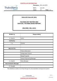
CONTROLLED DISTRIBUTIONREFERENCE :<str<strong>on</strong>g>SD</str<strong>on</strong>g>-<str<strong>on</strong>g>RP</str<strong>on</strong>g>-<str<strong>on</strong>g>AI</str<strong>on</strong>g>-<str<strong>on</strong>g>0629</str<strong>on</strong>g>DATE :June 09ISSUE : 01 PAGE : 9/353.2 <str<strong>on</strong>g>GG</str<strong>on</strong>g> Simulator ArchitectureThe <str<strong>on</strong>g>GG</str<strong>on</strong>g> simulator solves for the satellite dynamics al<strong>on</strong>g an orbit resulting from the applicati<strong>on</strong>of the Earth’s gravity field, the n<strong>on</strong>-c<strong>on</strong>servative envir<strong>on</strong>mental disturbances (atmospheric drag,wind, solar radiati<strong>on</strong> pressure, coupling with Earth’s magnetic field, etc.) and the DFAC c<strong>on</strong>trolforces and torques.The <str<strong>on</strong>g>GG</str<strong>on</strong>g> simulator is based <strong>on</strong> three different main modules: the Envir<strong>on</strong>ment, the Dynamicsand the Post-Processing <strong>on</strong>es. Figure 3-1 shows a descripti<strong>on</strong> of the <str<strong>on</strong>g>GG</str<strong>on</strong>g> simulator logicalbreakdown, highlighting the main data sets exchanged.The Envir<strong>on</strong>ment Module is in charge of computing the gravity field, the gravity gradient and then<strong>on</strong>-gravitati<strong>on</strong>al forces/torques acting <strong>on</strong> the spacecraft. These forces and torques are addedto the forces of the DFAC and AOCS actuators, in order to realize the <str<strong>on</strong>g>GG</str<strong>on</strong>g> orbit.Figure 3-1: <str<strong>on</strong>g>GG</str<strong>on</strong>g> simulator block-diagram.The three main modules of the simulator are the Envir<strong>on</strong>ment, the Dynamics and the Post-Processing modules. The blocks c<strong>on</strong>taining the c<strong>on</strong>trollers for the damping of the whirlingmoti<strong>on</strong> of PGB and of the test masses, the Drag Free and the Attitude and Orientati<strong>on</strong> of thesatellite are comp<strong>on</strong>ents of the Dynamics module.M032-ENAll rights reserved, 2007, Thales Alenia SpaceCONTROLLED DISTRIBUTION100181547K-EN
CONTROLLED DISTRIBUTIONREFERENCE :<str<strong>on</strong>g>SD</str<strong>on</strong>g>-<str<strong>on</strong>g>RP</str<strong>on</strong>g>-<str<strong>on</strong>g>AI</str<strong>on</strong>g>-<str<strong>on</strong>g>0629</str<strong>on</strong>g>DATE :June 09ISSUE : 01 PAGE : 10/35The Dynamics Module is in charge of computing the <str<strong>on</strong>g>GG</str<strong>on</strong>g> orbit and the relative dynamics of PGBw.r.t. the spacecraft, and of test masses w.r.t. PGB. This module has to take into account thegravity gradient acting <strong>on</strong> each body inside the <str<strong>on</strong>g>GG</str<strong>on</strong>g> spacecraft, and of the EP violating signalacting <strong>on</strong> the test masses. The c<strong>on</strong>trol laws for the damping of the PGB and test masseswhirling moti<strong>on</strong>, for the drag free and the AOCS are also dedicated blocks of the dynamicsmodule. It is also in charge of computing:• the capacitance measurements used to feed the Whirl c<strong>on</strong>trol of the PGB and of the testmasses (simulati<strong>on</strong> of the capacitance sensors, which feed the whirl c<strong>on</strong>troller)• the forces necessary to damp the PGB and test masses whirl moti<strong>on</strong>s (simulati<strong>on</strong> of theactuators, which realise the whirl c<strong>on</strong>troller commanded forces)• the effects due to temperature variati<strong>on</strong>s <strong>on</strong> the inertia properties of spacecraft, PGBand test masses• the effects due to temperature variati<strong>on</strong>s <strong>on</strong> the mechanical suspensi<strong>on</strong> (degrade of theCMRR xy and CMRR z ) and <strong>on</strong> the mechanical balancing of the read-out capacitancebridge• the effects of the temperature gradients <strong>on</strong> the mechanical suspensi<strong>on</strong> (degrade of theCMRR xy and CMRR z ) and <strong>on</strong> the mechanical balancing of the read-out capacitancebridge• the DFAC and AOCS sensors’ measurements• the DFAC and AOCS actuators’ forces and torques (simulati<strong>on</strong> of the FEEP/cold gasthrusters)• the ancillary telemetry data and the other spacecraft data• the <str<strong>on</strong>g>GG</str<strong>on</strong>g> science output (simulati<strong>on</strong> of the science capacitance sensors measurements,which feed the post-processing module)The Post-Processing Module is a self standing off line post-processor, which is in charge ofdetecting the EP violating signal in terms of differential test mass displacement starting from thescience output (and ancillary telemetry if needed). It is also used to compute accelerati<strong>on</strong>s,displacements and other useful vectors in the hereafter defined different reference frames.3.3 Simulator Reference FramesThe <str<strong>on</strong>g>GG</str<strong>on</strong>g> simulator describes the satellite orbit w.r.t. the most relevant reference frames for thescience missi<strong>on</strong>, which have been also used for the assessment of the Scientific Requirementsand of the Error Budget: the Inertial Reference Frame, the Local Vertical Reference Frame andthe Body Fixed Reference Frame.M032-ENAll rights reserved, 2007, Thales Alenia SpaceCONTROLLED DISTRIBUTION100181547K-EN
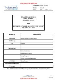
CONTROLLED DISTRIBUTIONREFERENCE :<str<strong>on</strong>g>SD</str<strong>on</strong>g>-<str<strong>on</strong>g>RP</str<strong>on</strong>g>-<str<strong>on</strong>g>AI</str<strong>on</strong>g>-<str<strong>on</strong>g>0629</str<strong>on</strong>g>DATE :June 09ISSUE : 01 PAGE : 11/353.3.1 Inertial Reference Frame – IRF –The fundamental Inertial Reference Frame of the missi<strong>on</strong> is currently realised by the J2000Equatorial Reference Frame (JERF), which is a Cartesian frame defined as follows (see Figure3-2):• Origin, O J2000 , located at the centre of the Earth• X J2000 axis at the intersecti<strong>on</strong> of the mean ecliptic plane with the mean equatorial plane atthe date of 01/01/2000 and pointing positively towards the vernal equinox• Z J2000 axis orthog<strong>on</strong>al to the mean equatorial plane at the date 01/01/2000• Y J2000 axis completing a right-handed reference frameThe satellite initial c<strong>on</strong>diti<strong>on</strong>s (positi<strong>on</strong>, velocity and attitude) are defined w.r.t. the InertialReference Frame. At t= 0 s, the satellite is lying al<strong>on</strong>g the X J2000 axis, and its velocity is al<strong>on</strong>gthe Y J2000 <strong>on</strong>e.Figure 3-2: The Inertial Reference Frame is the J2000 Equatorial Reference Frame.The centre is coincident with the Earth centre, the X axis is at the intersecti<strong>on</strong> of the meanecliptic plane with the mean equatorial plane (at the date Jan 1 st 2000), the Z axis is perpendicularto the mean equatorial plane (at the date Jan 1 st 2000), and the Y axis completes a right-handedreference frame.M032-ENAll rights reserved, 2007, Thales Alenia SpaceCONTROLLED DISTRIBUTION100181547K-EN
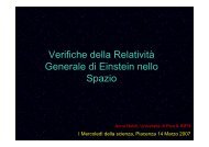
CONTROLLED DISTRIBUTIONREFERENCE :<str<strong>on</strong>g>SD</str<strong>on</strong>g>-<str<strong>on</strong>g>RP</str<strong>on</strong>g>-<str<strong>on</strong>g>AI</str<strong>on</strong>g>-<str<strong>on</strong>g>0629</str<strong>on</strong>g>DATE :June 093.3.2 Local Vertical Local Horiz<strong>on</strong>tal Reference Frame – LVLH –ISSUE : 01 PAGE : 12/35The LVLH reference frame is the sec<strong>on</strong>d fundamental frame: in this frame the EP violatingsignal always appears al<strong>on</strong>g a fixed directi<strong>on</strong> (in case of a perfect circular orbit, the Earth isfixed in this reference and the EP violating signal appears as a DC effect). In order to have theEP violating signal al<strong>on</strong>g the X LVLH axis, this reference frame is so defined (see Figure 3-3):• Origin, O LVLH , located at the satellite centre of mass (COM)• X LVLH axis directed from the centre of mass of the Earth to the satellite centre of mass(X LVLH axis identifies the local vertical from the point of view of the satellite COM)• Y LVLH axis points toward the directi<strong>on</strong> of moti<strong>on</strong> (it identifies the local horiz<strong>on</strong>tal projecti<strong>on</strong>of the velocity)• Z LVLH axis is perpendicular to the orbital plane and completes the right-handed coordinatesystem.Notice that because the spacecraft velocity vector rotates, to remain tangential to the orbit, theLVLH system also rotates about the Earth. The LVLH does not take into account the <str<strong>on</strong>g>GG</str<strong>on</strong>g>spinning about its symmetry axis.The Post-Processing module of the <str<strong>on</strong>g>GG</str<strong>on</strong>g> simulator aims to compute the test masses differentialdisplacement due to the EP violating signal w.r.t. the X LVLH , while the main comp<strong>on</strong>ent of then<strong>on</strong>-gravitati<strong>on</strong>al accelerati<strong>on</strong>s acting <strong>on</strong> the spacecraft external surface is al<strong>on</strong>g Y LVLH , i.e. 90°out of phase.Figure 3-3: The Local Vertical Local Horiz<strong>on</strong>tal Reference Frame (LVLH)The LVLH is a frame co-rotating with the spacecraft. Its origin is coincident with the satelliteCOM, its X axis is always from the Earth centre of mass to the satellite centre of mass, Y ispointing in the directi<strong>on</strong> of orbit moti<strong>on</strong> (it identifies the local horiz<strong>on</strong>tal plane) and its Z axis isperpendicular to the orbital plane and completes the right-handed coordinate system.M032-ENAll rights reserved, 2007, Thales Alenia SpaceCONTROLLED DISTRIBUTION100181547K-EN
CONTROLLED DISTRIBUTIONREFERENCE :<str<strong>on</strong>g>SD</str<strong>on</strong>g>-<str<strong>on</strong>g>RP</str<strong>on</strong>g>-<str<strong>on</strong>g>AI</str<strong>on</strong>g>-<str<strong>on</strong>g>0629</str<strong>on</strong>g>DATE :June 09ISSUE : 01 PAGE : 13/353.3.3 Body Fixed Reference Frame – BF –The Body Fixed Reference Frame is the frame “attached” to the spinning satellite and definedby means of physical markers <strong>on</strong> the true structure. The necessity of assuming <strong>on</strong>e spacecraftfixed reference frame is dictated by the fact that DFC sensors and actuators are fixed withrespect to the satellite structure (PGB and test masses are mechanically suspended and duringscience operati<strong>on</strong>s are not fixed with respect to the satellite structure). The BF frame is definedaccording to the following prescripti<strong>on</strong>:• The Z BF axis corresp<strong>on</strong>ds to the central axis of the PGB c<strong>on</strong>necting cylindrical tube(when the PGB is locked to the satellite). It is nominally the spinning axis of the satellite,and the positive directi<strong>on</strong> is the same of the angular rate vector. In the <str<strong>on</strong>g>GG</str<strong>on</strong>g> simulator theZ BF axis is the satellite spin axis and it is coincident with the PGB symmetry axis at t=0 s.• The reference origin, O BF , is located <strong>on</strong> the Z BF axis. When PGB and test masses arelocked with respect to the satellite, the origin marker is placed in order to individuate thepositi<strong>on</strong> al<strong>on</strong>g the Z BF axis of the test masses equatorial plane. O BF is nominallycoincident with the satellite centre of mass (when PGB and proof masses are locked). Inthe <str<strong>on</strong>g>GG</str<strong>on</strong>g> simulator, O BF is coincident with the satellite centre of mass.• X BF and Y BF axes lie <strong>on</strong> the plane c<strong>on</strong>taining O BF and perpendicular to the Z BF axis. Eachaxis passes through the median plane of the two pairs of capacitance plates in betweenthe test masses. A dedicated marker identifies the axes X BF and Y BF , which are chosen tocomplete with the Z BF axis a right-handed coordinate system. In the <str<strong>on</strong>g>GG</str<strong>on</strong>g> simulator, it isassumed that the capacitance plates defining the X BF axis are the <strong>on</strong>es <strong>on</strong> the X J2000 at t= 0.3.4 Simulator Envir<strong>on</strong>ment ModuleThis block is dedicated to the computati<strong>on</strong> of the forces and torques acting <strong>on</strong> the spacecraftand resulting from the interacti<strong>on</strong> with the orbital envir<strong>on</strong>ment. As such, this module computesthe gravity force, the gravity gradient torque, the aerodynamic force and torques, the magnetictorque, the solar radiati<strong>on</strong> pressure force and torque. It includes:• the Earth gravity field, with gravitati<strong>on</strong>al c<strong>on</strong>stant GM = 3.986004418·1014 m 3 /s 2 ,according to the EGM96 Earth Gravity field soluti<strong>on</strong>, and Earth Mean Radius = 6378144m. The gravity gradient torque taking into account for J2 effect is also applied <strong>on</strong> eachbody.• the MSIS86 atmospheric model for the computati<strong>on</strong> of the air density, temperature andchemical compositi<strong>on</strong> al<strong>on</strong>g the satellite orbit. The F10 and F10.B indexes related to theSolar activity and the Geomagnetic indexes Ap and Kp are used to feed the MSIS model.• a model of the Earth’s magnetic field derived from the Oersted satellite measurements• the celestial bodies ephemeredes computati<strong>on</strong>M032-ENAll rights reserved, 2007, Thales Alenia SpaceCONTROLLED DISTRIBUTION100181547K-EN
CONTROLLED DISTRIBUTIONREFERENCE :<str<strong>on</strong>g>SD</str<strong>on</strong>g>-<str<strong>on</strong>g>RP</str<strong>on</strong>g>-<str<strong>on</strong>g>AI</str<strong>on</strong>g>-<str<strong>on</strong>g>0629</str<strong>on</strong>g>DATE :June 09ISSUE : 01 PAGE : 14/35The solar radiati<strong>on</strong> pressure and Earth albedo are computed modeling the satellite surface as aset of <strong>on</strong>e cylinder and two simple flat surfaces. The pressures due to the solar and Earthalbedo, which depend mainly <strong>on</strong> the distance from the Sun, <strong>on</strong> the altitude of the satellite duringits orbit, and <strong>on</strong> the angle between the Sun directi<strong>on</strong> and the local-vertical directi<strong>on</strong>, iscomputed for each elementary surface. Once the pressures have been computed, thecorresp<strong>on</strong>ding forces for each surface are obtained c<strong>on</strong>sidering the normal and tangentcomp<strong>on</strong>ents depending <strong>on</strong> the surface extensi<strong>on</strong> and <strong>on</strong> the aspect angle of the surface withrespect to fluxes directi<strong>on</strong>. The force is computed for each surface and applied to the surface’scentre of pressure. The resulting force and torque <strong>on</strong> the centre of mass of each body is thencomputed.3.5 Simulator Dynamics ModuleThe complete <str<strong>on</strong>g>GG</str<strong>on</strong>g> system, which takes into account the spacecraft, the Pico Gravity Box, theinner and outer test masses, has been simulated by using the DCAP (Dynamics and C<strong>on</strong>trolAnalysis Package) software package developed by Thales Alenia Space under ESA c<strong>on</strong>tract.An additi<strong>on</strong>al dummy body has been introduced in order to solve for the orbit without introducingnumerical errors due to the high spinning frequency of the spacecraft itself (the orbit is solved inthe reference frame of the first body of the kinematics chain). The dummy body is a massivepoint coincident with the spacecraft centre of mass: its moti<strong>on</strong> w.r.t. the Inertial ReferenceFrame is defined by the degrees of freedom (3) of the Hinge 1, which c<strong>on</strong>nects it (Node 1) tothe origin of the IRF. Moreover, the dummy body identifies the origin of the LVLH referenceframe: the vector pointing towards the Earth identifies the X-axis, its velocity identifies the Y-axis(al<strong>on</strong>g-track directi<strong>on</strong>), and the orbit angular velocity is al<strong>on</strong>g the Z-axis. The bodies arecharacterized by the up-to-date values of the mass and inertia properties, while the dummybody – Body 1 - is a unitary massive point coincident with the spacecraft centre of mass (Node10). The bodies of the <str<strong>on</strong>g>GG</str<strong>on</strong>g> dynamical model (schematically represented in Figure 3-4) and thedegrees of freedom (summarised in Table 3-1) are defined as follows:• Body 1 is the dummy body. Its representative node (Node 1) is coincident with thespacecraft centre of mass. The Hinge 1, which c<strong>on</strong>nects the IRF to Node 1, has 3degrees of freedom: its translati<strong>on</strong> completely describes the orbit moti<strong>on</strong> of thespacecraft.• Body 2 is the spacecraft. The satellite has its centre of mass (Node 10) coincident withthe dummy body (Node 1). The null-length Hinge 2, which c<strong>on</strong>nects the LVLH origin tothe s/c centre of mass, permits satellite rotati<strong>on</strong>s <strong>on</strong>ly. In particular, the rotati<strong>on</strong> about theZ axis defines the spin w.r.t. the LVLH.• Body 3 is the Pico-Gravity Box (PGB). The Hinge 3, which c<strong>on</strong>nects the s/c centre ofmass (Node 10) to the PGB centre of mass (Node 20), provides the 6 degrees offreedom (3 rotati<strong>on</strong>s and 3 translati<strong>on</strong>s) of the PGB-s/c relative moti<strong>on</strong>.• Body 4 is the outer (external) test mass (TMe). The Hinge 4, which c<strong>on</strong>nects the PGBcentre of mass (Node 20) to the TMe centre of mass (Node 30), provides the 6 degreesof freedom (3 rotati<strong>on</strong>s and 3 translati<strong>on</strong>s) of the TMe-PGB relative moti<strong>on</strong>.M032-ENAll rights reserved, 2007, Thales Alenia SpaceCONTROLLED DISTRIBUTION100181547K-EN
CONTROLLED DISTRIBUTIONREFERENCE :<str<strong>on</strong>g>SD</str<strong>on</strong>g>-<str<strong>on</strong>g>RP</str<strong>on</strong>g>-<str<strong>on</strong>g>AI</str<strong>on</strong>g>-<str<strong>on</strong>g>0629</str<strong>on</strong>g>DATE :June 09ISSUE : 01 PAGE : 15/35• Body 5 is the inner test mass (TMi). The Hinge 5, which c<strong>on</strong>nects the PGB centre ofmass (Node 20) to the TMi centre of mass (Node 40), provides the 6 degrees of freedom(3 rotati<strong>on</strong>s and 3 translati<strong>on</strong>s) of the TMi-PGB relative moti<strong>on</strong>.This type of multi-body c<strong>on</strong>necti<strong>on</strong> grants an open-loop kinematics topology, with no need forcut-joint hinges. All hinges are described by a Euler sequence Type 1, x-y-z. The active degreesof freedom (DoF) defined by hinges can be differently set depending <strong>on</strong> the required type ofsimulati<strong>on</strong>.Hinge Id. Transl. Dofs (x,y,z) Rotati<strong>on</strong>al Dofs (x,y,z)1 F, F, F L, L, L2 L, L, L F, F, F3÷5 F, F, F F, F, FNote : L = Hinge DoF Locked F = Hinge DoF FreeTable 3-1: Translati<strong>on</strong> and rotati<strong>on</strong>al degrees of freedom of the hinges defining thekinematics chain of the <str<strong>on</strong>g>GG</str<strong>on</strong>g> system. Hinge 1 c<strong>on</strong>nects the IRF to the dummy body, andthe null-length Hinge 2 c<strong>on</strong>nects the dummy body to the spacecraft centre of mass.The Hinge 1 defines also the initial c<strong>on</strong>diti<strong>on</strong> for the <str<strong>on</strong>g>GG</str<strong>on</strong>g> orbit (w.r.t. the IRF), with thec<strong>on</strong>venti<strong>on</strong> that at t = 0 the satellite positi<strong>on</strong> is (R ⊕ + h, 0, 0) and the satellite velocity is (0, v y , 0),with R ⊕ the Earth equatorial radius and h the <str<strong>on</strong>g>GG</str<strong>on</strong>g> orbit altitude. The Hinge 2 defines instead thesatellite spin w.r.t. the IRF: initially it has been assumed to be 2 Hz, but it is going to be updatedto 1 Hz, according to the last analyses, which have been performed in order to verify thecapability of FEEPs and cold gas thrusters for the drag free compensati<strong>on</strong>.The mass and inertia properties used in the simulator have been fixed at the beginningaccording to the last Phase A <str<strong>on</strong>g>Report</str<strong>on</strong>g> descripti<strong>on</strong> (2000); then, they have been updatedaccording to the March review mass budget. At the end they shall be updated according to thelast mass budget. The mass and inertia properties are not c<strong>on</strong>tinuously updated in order tomake more efficient the “growth” of the simulator (the main job is adding all the possiblespurious effect masking or competing with the EP signal).M032-ENAll rights reserved, 2007, Thales Alenia SpaceCONTROLLED DISTRIBUTION100181547K-EN
CONTROLLED DISTRIBUTIONREFERENCE :<str<strong>on</strong>g>SD</str<strong>on</strong>g>-<str<strong>on</strong>g>RP</str<strong>on</strong>g>-<str<strong>on</strong>g>AI</str<strong>on</strong>g>-<str<strong>on</strong>g>0629</str<strong>on</strong>g>DATE :June 09ISSUE : 01 PAGE : 16/35Figure 3-4: Schematic model of the <str<strong>on</strong>g>GG</str<strong>on</strong>g> dynamics system.Logical scheme of the dynamical model implemented within DCAP software code for finiteelement simulati<strong>on</strong> of the space experiment. The z axis is the spin/symmetry axis of the system;all elastic c<strong>on</strong>necti<strong>on</strong>s al<strong>on</strong>g z are very stiff; the plane of sensitivity is perpendicular to z. Themodel encompasses all bodies (spacecraft, PGB and 2 test masses), each <strong>on</strong>e with its 6 degreesof freedom in 3D (3 for translati<strong>on</strong> and 3 for rotati<strong>on</strong>), mass and moments of inertia. All n<strong>on</strong> rigidcomp<strong>on</strong>ents of the system (sketched as springs) are implemented with their designed stiffness(in the sensitive plane as well as in the z directi<strong>on</strong>) and mechanical quality factors Q forsimulati<strong>on</strong>.M032-ENAll rights reserved, 2007, Thales Alenia SpaceCONTROLLED DISTRIBUTION100181547K-EN
CONTROLLED DISTRIBUTIONREFERENCE :<str<strong>on</strong>g>SD</str<strong>on</strong>g>-<str<strong>on</strong>g>RP</str<strong>on</strong>g>-<str<strong>on</strong>g>AI</str<strong>on</strong>g>-<str<strong>on</strong>g>0629</str<strong>on</strong>g>DATE :June 09ISSUE : 01 PAGE : 17/35The mechanical suspensi<strong>on</strong>s c<strong>on</strong>necting the PGB to the spacecraft and the test masses to thePGB, which are schematically represented by springs in Figure 3-4, are implemented in order toprovide realistic suspensi<strong>on</strong> modes (according to the <str<strong>on</strong>g>GG</str<strong>on</strong>g> <strong>on</strong> the Ground measured values) andtransfer functi<strong>on</strong> (see Table 3-2). The PGB-s/c suspensi<strong>on</strong> is also characterised by its realisticdissipative term, corresp<strong>on</strong>ding to a mechanical quality factor Q PGB ≅ 90, in order to provide themost realistic representati<strong>on</strong> of the PGB-s/c dynamics behaviour: the PGB-s/c relative moti<strong>on</strong>not <strong>on</strong>ly must be measured in order to feed its c<strong>on</strong>trol of the whirl moti<strong>on</strong>, but provides also theinput of the DFAC c<strong>on</strong>trol, which is a key point for the <str<strong>on</strong>g>GG</str<strong>on</strong>g> science performance.<str<strong>on</strong>g>GG</str<strong>on</strong>g>sub-systemPlanar oscillati<strong>on</strong> period [ s ] Axial oscillati<strong>on</strong> period [ s ]s/c-PGB 360 30PGB-TMe 30 < T CMxy < 120 30PGB-TMi 30 < T CMxy < 120 30TMe-TMi 540 0Table 3-2: Oscillati<strong>on</strong> periods of the various <str<strong>on</strong>g>GG</str<strong>on</strong>g> subsystems al<strong>on</strong>g the satellite spin axisand in the plane perpendicular to it.The dissipati<strong>on</strong> of the PGB-test masses suspensi<strong>on</strong>s is instead assumed to be greater andgreater than the true <strong>on</strong>e, by adopting a corresp<strong>on</strong>ding mechanical quality factor Q TM ≅ 500 (vs.a true value of Q TM ≅ 20000): this choice is necessary in order to have a whirl-radius doublingtime t rw2 of the order of t rw2 ≈ 10000 sec (vs. a true value of t rw2 ≈ 500000 sec). This shorter t rw2permits to carry out simulati<strong>on</strong>s covering a missi<strong>on</strong> time durati<strong>on</strong> not l<strong>on</strong>ger than200000÷300000 sec, but which cover all the relevant aspects in terms of disturbing effects andscience performance (the EP signal is in fact detected). The adopti<strong>on</strong> of the true value for themechanical quality factor of the PGB-test masses suspensi<strong>on</strong> would force the length of <strong>on</strong>escience performance simulati<strong>on</strong> to several milli<strong>on</strong>s of sec<strong>on</strong>ds, just to verify the growth of thewhirling moti<strong>on</strong>! It is apparent that there is nor loss of generality, neither a “favourable”assumpti<strong>on</strong> in this choice.The EP violating signal is simulated with a force with amplitude F EP = m TM · g(h) · η N, which isdirected from the Earth centre of mass to the centre of mass of the outer test body <strong>on</strong>ly (it is apure differential force for the test masses). This mean that the EP violating force is alwaysdirected al<strong>on</strong>g the X LVLH axis. The mass of the proof body is 10 kg, the value of the local gravitysensed from the test mass depends <strong>on</strong> the <str<strong>on</strong>g>GG</str<strong>on</strong>g> altitude, and it is about 8÷8.4 m/s 2 . The Eötvösparameter η is an input value for the simulator, with η in the range of 10 -17 ÷10 -13 .M032-ENAll rights reserved, 2007, Thales Alenia SpaceCONTROLLED DISTRIBUTION100181547K-EN
CONTROLLED DISTRIBUTIONREFERENCE :<str<strong>on</strong>g>SD</str<strong>on</strong>g>-<str<strong>on</strong>g>RP</str<strong>on</strong>g>-<str<strong>on</strong>g>AI</str<strong>on</strong>g>-<str<strong>on</strong>g>0629</str<strong>on</strong>g>DATE :June 09ISSUE : 01 PAGE : 18/35High-fidelity models represent sensors feeding the c<strong>on</strong>trol algorithms and the actuators(FEEPs/cold gas thrusters and spinning-up gas thrusters), which are in charge of generating theDFAC and AOCS commanded forces and torques. The high-fidelity models for sensor andactuators have to account for intrinsic noises, transfer functi<strong>on</strong>s, n<strong>on</strong> linearity, mounting errors,sensor/actuators inner geometrical imperfecti<strong>on</strong>s (see Figure 3-5), temperature fluctuati<strong>on</strong>s,quantizati<strong>on</strong> and all the other effects which can degrade the scientific performance of thesensors/actuators, since the goal of the simulati<strong>on</strong> is predicting the realistic missi<strong>on</strong> scientificperformance.Figure 3-5: Sensor/actuator geometrical imperfecti<strong>on</strong>: mispositi<strong>on</strong>ing, misalignment,scale factor error and coupling error.The simulati<strong>on</strong> of sensor/actuator noise and of temperature fluctuati<strong>on</strong> is based <strong>on</strong> thesuperpositi<strong>on</strong> of deterministic noise (implemented by sinusoidal terms) and of stochastic noise(implemented by noise shaping technique). With the noise shaping technique, a properlydevised (in the frequency domain) noise shaping filter is used to provide the desired shape to itsfeeding unitary band limited white noise. The block-diagram of the white noise shapingtechnique is reported in Figure 3-6: a unitary (<strong>on</strong>e-sided) white noise is passed through ananalog/digital filter that builds up the requested noise Spectral Density and which integrates alsoan anti-aliasing filter (if necessary). The output of the filter is then decimated (if requested) andsaved into a dedicated variable.M032-ENAll rights reserved, 2007, Thales Alenia SpaceCONTROLLED DISTRIBUTION100181547K-EN
CONTROLLED DISTRIBUTIONREFERENCE :<str<strong>on</strong>g>SD</str<strong>on</strong>g>-<str<strong>on</strong>g>RP</str<strong>on</strong>g>-<str<strong>on</strong>g>AI</str<strong>on</strong>g>-<str<strong>on</strong>g>0629</str<strong>on</strong>g>DATE :June 09ISSUE : 01 PAGE : 19/35Figure 3-6: Block diagram of the white noise shaping technique. A white noise withunitary (<strong>on</strong>e-sided) Spectral Density is passed through a shaping filter (applying also theanti-aliasing, if necessary) and decimated (if required) before saving the output into adedicated variable.Figure 3-7 shows as example the time histories of the fluctuating temperature, temp_fluct,realized according to the white noise shaping technique. Figure 3-8 shows the Spectral Density(<str<strong>on</strong>g>SD</str<strong>on</strong>g>) as computed from the simulated time history, vs the desired analytic <str<strong>on</strong>g>SD</str<strong>on</strong>g>: the desiredanalytic <str<strong>on</strong>g>SD</str<strong>on</strong>g> can be superimposed to the computed <strong>on</strong>e.Figure 3-7: Time history of the fluctuating comp<strong>on</strong>ent of temperature obtained with thewhite noise shaping techniqueM032-ENAll rights reserved, 2007, Thales Alenia SpaceCONTROLLED DISTRIBUTION100181547K-EN
CONTROLLED DISTRIBUTIONREFERENCE :<str<strong>on</strong>g>SD</str<strong>on</strong>g>-<str<strong>on</strong>g>RP</str<strong>on</strong>g>-<str<strong>on</strong>g>AI</str<strong>on</strong>g>-<str<strong>on</strong>g>0629</str<strong>on</strong>g>DATE :June 09ISSUE : 01 PAGE : 20/35Figure 3-8: Spectral density of the temperature fluctuati<strong>on</strong> computed from the simulatedtime history vs. the Spectral density desired analitic law.The above cited technique provides the capability of adding the temperature effects sensed atthe level of the test masses (thermal noise, temperature fluctuati<strong>on</strong>), of the mechanicalbalancing of the science read-out, and of the CMRR xy and CMRR z variati<strong>on</strong> due to temperature.An analytic functi<strong>on</strong> for the temperature variati<strong>on</strong> sensed from spacecraft and PGB shall beinstead modelled in order to introduce their inertia variati<strong>on</strong>s.The simulator architecture allows easy incorporati<strong>on</strong> of models generated by a wide range ofsoftware tools, such as DCAP-RT (Dynamics and C<strong>on</strong>trol Analysis Package for Real Time,TAS-I developed dynamics package), and commercial off the shelf tools like Matlab/Simulinkand Real Time Workshop.3.6 Post-Processing ModuleThe <str<strong>on</strong>g>GG</str<strong>on</strong>g> sensor and actuators are fixed w.r.t. the spinning satellite: this means that the detecti<strong>on</strong>of the EP violati<strong>on</strong> signal and of the other interesting informati<strong>on</strong> (n<strong>on</strong>-gravitati<strong>on</strong>al accelerati<strong>on</strong>,whirling moti<strong>on</strong>, temperature effects, gravity gradient c<strong>on</strong>tributi<strong>on</strong>s, etc.) is completely maskedby the <str<strong>on</strong>g>GG</str<strong>on</strong>g> spinning frequency.The Post-Processing module, which is in embry<strong>on</strong>ic status (Phase A level), c<strong>on</strong>sists of a Matlabmacros package, which has been implemented in order to allow the transformati<strong>on</strong> of all thesensor measurements from the BF to the IRF and to the LVLH reference frames. Also theancillary informati<strong>on</strong> about the satellite, PGB and test masses dynamics is provided in all thereference frames, in order to allow the science performance check by using the time historiesgenerated by the simulator. The implemented macro package requires the Signal ProcessingM032-ENAll rights reserved, 2007, Thales Alenia SpaceCONTROLLED DISTRIBUTION100181547K-EN
CONTROLLED DISTRIBUTIONREFERENCE :<str<strong>on</strong>g>SD</str<strong>on</strong>g>-<str<strong>on</strong>g>RP</str<strong>on</strong>g>-<str<strong>on</strong>g>AI</str<strong>on</strong>g>-<str<strong>on</strong>g>0629</str<strong>on</strong>g>DATE :June 09ISSUE : 01 PAGE : 21/35and Statistics Matlab Toolboxes. The coding of this module is such that it should be easy a fullporting to the GNU Octave envir<strong>on</strong>ment, which is a free Matlab cl<strong>on</strong>e providing also packagesequivalent to the Signal Processing and Statistics Toolboxes.The Post-Processing module allows the analysis <strong>on</strong> both the time and frequency domain,providing results in terms of Amplitude Spectrum and Spectral Density of the interesting signals(e.g. Fourier analysis of the n<strong>on</strong>-gravitati<strong>on</strong>al accelerati<strong>on</strong>s w.r.t to IRF and Spectral Densityaccelerati<strong>on</strong>s and displacements).A further development of this module is foreseen in case of advance in Phase B of the <str<strong>on</strong>g>GG</str<strong>on</strong>g>science missi<strong>on</strong>.M032-ENAll rights reserved, 2007, Thales Alenia SpaceCONTROLLED DISTRIBUTION100181547K-EN
CONTROLLED DISTRIBUTIONREFERENCE :<str<strong>on</strong>g>SD</str<strong>on</strong>g>-<str<strong>on</strong>g>RP</str<strong>on</strong>g>-<str<strong>on</strong>g>AI</str<strong>on</strong>g>-<str<strong>on</strong>g>0629</str<strong>on</strong>g>DATE :June 09ISSUE : 01 PAGE : 22/354. SCIENCE PERFORMANCE SIMULATIONThe results of <strong>on</strong>e science performance simulati<strong>on</strong> are hereafter reported in order to validatethe <str<strong>on</strong>g>GG</str<strong>on</strong>g> simulator and to show its capabilities and usefulness. This simulati<strong>on</strong> was carried out inorder to check the real basis of the experiment, i.e. the capability to detect the EP violatingsignal, taking into account:• the gravity field and the gravity gradient acting <strong>on</strong> the spacecraft• the n<strong>on</strong> gravitati<strong>on</strong>al forces acting <strong>on</strong> the spacecraft surface• the dissipati<strong>on</strong> of the mechanical suspensi<strong>on</strong>s (whirling moti<strong>on</strong>s and whirl c<strong>on</strong>trols ofPGB and test masses)• the gravity gradient acting <strong>on</strong> the proof masses.For this exercise, the sensors’ and actuators’ noise and imperfecti<strong>on</strong>s have been neglected, inorder to compare the simulator’s results vs. the analytical predicti<strong>on</strong>s. Moreover, it is assumed aperfect Comm<strong>on</strong> Mode Rejecti<strong>on</strong> Ratio of the mechanical suspensi<strong>on</strong>s (χ CMRRxy = 0, χ CMRRz = 0),and a perfect mechanical balancing of the science capacitance bridge (χ bridge = 0). Due to theperfect rejecti<strong>on</strong> of the comm<strong>on</strong> mode by means of the mechanical suspensi<strong>on</strong>, the DFC for thepartial compensati<strong>on</strong> of the n<strong>on</strong>-gravitati<strong>on</strong>al disturbances is not working in this simulati<strong>on</strong>. Thesatellite spin frequency has been updated to the new default value: 1 Hz. For this exercise theoscillati<strong>on</strong> periods of the test masses and of PGB have been modified (compare Table 4-1 vs.Table 3-2) in order to largely amplify the displacements due to the inertial accelerati<strong>on</strong> sensedby the bodies (this is due to the fact that the adopted envir<strong>on</strong>ment cannot be c<strong>on</strong>sidered a worstcase scenario).<str<strong>on</strong>g>GG</str<strong>on</strong>g>sub-systemValues of simulated Planaroscillati<strong>on</strong> period [ s ]Values of simulated axialoscillati<strong>on</strong> period [ s ]s/c-PGB 295.04 295.04PGB-TMe T CMxy = 113 113PGB-TMi T CMxy < 113 113TMe-TMi 500 0Table 4-1: Oscillati<strong>on</strong> periods of the various <str<strong>on</strong>g>GG</str<strong>on</strong>g> subsystem al<strong>on</strong>g the satellite spin axisand in the plane perpendicular to it adopted for this science performance simulati<strong>on</strong>.M032-ENAll rights reserved, 2007, Thales Alenia SpaceCONTROLLED DISTRIBUTION100181547K-EN
CONTROLLED DISTRIBUTIONREFERENCE :<str<strong>on</strong>g>SD</str<strong>on</strong>g>-<str<strong>on</strong>g>RP</str<strong>on</strong>g>-<str<strong>on</strong>g>AI</str<strong>on</strong>g>-<str<strong>on</strong>g>0629</str<strong>on</strong>g>DATE :June 09ISSUE : 01 PAGE : 24/354.1 Satellite accelerati<strong>on</strong> in the LVLH reference frameOne of the main features of the simulator is the capability to compare the accelerati<strong>on</strong>s thathave to be compensated/rejected and the accelerati<strong>on</strong> that has to be detected: the n<strong>on</strong>gravitati<strong>on</strong>al forces acting <strong>on</strong> the external surface of the spacecraft provides an inertialaccelerati<strong>on</strong> that is several orders of magnitude bigger than the EP violating signal. The LVLHcomp<strong>on</strong>ents of the spacecraft n<strong>on</strong> gravitati<strong>on</strong>al accelerati<strong>on</strong> have been computed by using thePost-Processing module and shown in Figure 4-2, Figure 4-3 and Figure 4-4 below.Figure 4-4, which shows a zoom of the time histories of the spacecraft accelerati<strong>on</strong> al<strong>on</strong>g theZ LVLH axis, highlights also the oscillating term due to the mechanical coupling with the PGB. Ithas to be pointed out here that the realized simulati<strong>on</strong> is not yet the worst case scenario for theenvir<strong>on</strong>ment, and that it is just <strong>on</strong>e possible representati<strong>on</strong> for the satellite dynamics. The worstcase scenario for the envir<strong>on</strong>ment shall be taken into account <strong>on</strong>ce the satellite c<strong>on</strong>figurati<strong>on</strong>and the possible launch date will be frozen. The short eclipse periods are also visible: during theeclipse the mean value of accelerati<strong>on</strong> is zero.Figure 4-2: Time history of the spacecraft n<strong>on</strong> gravitati<strong>on</strong>al accelerati<strong>on</strong> al<strong>on</strong>g the X LVLHaxis, i.e. al<strong>on</strong>g the same directi<strong>on</strong> of the EP violating signal, whose amplitude is 8.4⋅10 -17m/s 2 .M032-ENAll rights reserved, 2007, Thales Alenia SpaceCONTROLLED DISTRIBUTION100181547K-EN
CONTROLLED DISTRIBUTIONREFERENCE :<str<strong>on</strong>g>SD</str<strong>on</strong>g>-<str<strong>on</strong>g>RP</str<strong>on</strong>g>-<str<strong>on</strong>g>AI</str<strong>on</strong>g>-<str<strong>on</strong>g>0629</str<strong>on</strong>g>DATE :June 09ISSUE : 01 PAGE : 25/35Figure 4-3: Time history of the spacecraft n<strong>on</strong> gravitati<strong>on</strong>al accelerati<strong>on</strong> al<strong>on</strong>g the Y LVLHaxis, i.e. perpendicular to the directi<strong>on</strong> of the EP violating signal, whose amplitude is8.4⋅10 -17 m/s 2 .Figure 4-4: Time history of the satellite n<strong>on</strong> gravitati<strong>on</strong>al accelerati<strong>on</strong> al<strong>on</strong>g Z IRFZoom of the time history of the satellite n<strong>on</strong> gravitati<strong>on</strong>al accelerati<strong>on</strong> al<strong>on</strong>g the Z IRF axis (Z LVLH isparallel to it, there is <strong>on</strong>ly translati<strong>on</strong> of the origin), i.e. perpendicular to the orbit plane. Therelative moti<strong>on</strong> of PGB w.r.t. the spacecraft is represented by the oscillati<strong>on</strong>s of the signal. Theshort eclipse periods are also visible (accelerati<strong>on</strong> mean value is zero).M032-ENAll rights reserved, 2007, Thales Alenia SpaceCONTROLLED DISTRIBUTION100181547K-EN
CONTROLLED DISTRIBUTIONREFERENCE :<str<strong>on</strong>g>SD</str<strong>on</strong>g>-<str<strong>on</strong>g>RP</str<strong>on</strong>g>-<str<strong>on</strong>g>AI</str<strong>on</strong>g>-<str<strong>on</strong>g>0629</str<strong>on</strong>g>DATE :June 09ISSUE : 01 PAGE : 26/354.2 PGB-s/c displacementThe PGB-s/c displacement is analyzed in the Drag Free c<strong>on</strong>trol document [RD 16].4.3 Comm<strong>on</strong> mode moti<strong>on</strong> of the test massesThe displacement of each test mass w.r.t. the PGB provides the informati<strong>on</strong> about the requiredoverall rejecti<strong>on</strong> of the comm<strong>on</strong> mode accelerati<strong>on</strong>. The overall external n<strong>on</strong>-gravitati<strong>on</strong>al forceaffecting the spacecraft moti<strong>on</strong> is sensed from the test masses as inertial force: in principle it isa pure comm<strong>on</strong> mode for them, such as in this simulati<strong>on</strong>. In true life, it is anyway necessary toreduce this comm<strong>on</strong> mode accelerati<strong>on</strong> for mainly three reas<strong>on</strong>s:• the comm<strong>on</strong> mode accelerati<strong>on</strong> displaces each test mass, and this displacement has alimited range: the gap of the science capacitance plates• the comm<strong>on</strong> mode rejecti<strong>on</strong> of the test masses mechanical suspensi<strong>on</strong> is not 0 (i.e. afracti<strong>on</strong> of the comm<strong>on</strong> mode accelerati<strong>on</strong> is transformed into differential accelerati<strong>on</strong>,which competes with the interesting signal to be detected)• the capacitance read-out, which is in charge of detecting the test masses relativedisplacement due to an EP violati<strong>on</strong>, is sensitive to both comm<strong>on</strong> and differential mode.Hence (a) Its dynamic range must be not saturated; (b) Its rejecti<strong>on</strong> of the comm<strong>on</strong> modeis limited.In order to have a very small gap for the capacitance plates of the science read-out (i.e. highsensitivity), the external n<strong>on</strong>-gravitati<strong>on</strong>al accelerati<strong>on</strong> is partially compensated by means of anactive Drag Free C<strong>on</strong>trol, which reduces the inertial accelerati<strong>on</strong> sensed from the PGB and testmasses at the orbit frequency. The remaining comm<strong>on</strong> mode accelerati<strong>on</strong> is rejected from themechanical suspensi<strong>on</strong>. In the IRF, the residual comm<strong>on</strong> mode accelerati<strong>on</strong> sensed from theextPGB and test masses at the orbit frequency is a CMxy = χ DFCxy × a NG xy. The a CMxy accelerati<strong>on</strong> isresp<strong>on</strong>sible of the el<strong>on</strong>gati<strong>on</strong> of the “springs” c<strong>on</strong>necting the PGB to the spacecraft and the testmasses to the PGB in the test masses equatorial plane XY.In this simulati<strong>on</strong>, whose main objective is the simulator validati<strong>on</strong>, χ DFCxy = 1 (no DFC) and soexta CMxy = a . The inertial accelerati<strong>on</strong>, which becomes a differential term due to theNG xymechanical balance suspensi<strong>on</strong> imperfecti<strong>on</strong>s, is ainerDM = a CMxy × χ CMRRxy , wih χ CMRRxy thesuspensi<strong>on</strong> Comm<strong>on</strong> Mode Rejecti<strong>on</strong> Ratio. As already menti<strong>on</strong>ed above, in this simulati<strong>on</strong>χ CMRRxy = 0, instead of χ CMRRxy = 10 -5 iner(perfect comm<strong>on</strong> mode rejecti<strong>on</strong>): so, a DM = 0. This meansthat the PGB-test mass displacement is the largest possible <strong>on</strong>e, but that at the same time thedifferential displacement is not affected by this large value. In other words, in such ac<strong>on</strong>figurati<strong>on</strong> the simulator can be used at the same time to check the level of violati<strong>on</strong> of therequirements <strong>on</strong> the test masses comm<strong>on</strong> mode displacement in case of n<strong>on</strong> drag free mode,and at the same time it can be used to detect the EP violating signal.M032-ENAll rights reserved, 2007, Thales Alenia SpaceCONTROLLED DISTRIBUTION100181547K-EN
CONTROLLED DISTRIBUTIONREFERENCE :<str<strong>on</strong>g>SD</str<strong>on</strong>g>-<str<strong>on</strong>g>RP</str<strong>on</strong>g>-<str<strong>on</strong>g>AI</str<strong>on</strong>g>-<str<strong>on</strong>g>0629</str<strong>on</strong>g>DATE :June 09ISSUE : 01 PAGE : 27/35The Post-Processing module provides the time histories of the satellite positi<strong>on</strong>, velocity andaccelerati<strong>on</strong> in both the IRF and LVLH reference frames. It also provides the s/c-PGB and thePGB-test masses displacement, velocity and accelerati<strong>on</strong> in both the IRF and LVLH referenceframes, thus removing the high frequency comp<strong>on</strong>ents, which would make figures of BF timehistories almost useless.The following pictures show the time histories of the TMe comm<strong>on</strong> mode displacement al<strong>on</strong>gthe three axes of the LVLH reference frame, as computed from the post-processing module.Figure 4-5 shows the displacement of the outer test mass w.r.t. the PGB al<strong>on</strong>g X LVLH : themaximum displacement (some tens of micr<strong>on</strong>s) is by far smaller than the gap between thescience capacitance plate and the inner surface of the outer proof body (2.5 mm). While in thissimulati<strong>on</strong> the <strong>on</strong>ly difference of proof masses displacement is due to the EP violating signaland to gravity gradient (the differential displacement due to EP violati<strong>on</strong> is ∆x EP =F EP ×(T diff ) 2 /(4×m TM ×π 2 ) ≅ 0.5 pm), in true life a fracti<strong>on</strong> χ CMRRxy = 10 -5 of the observed comm<strong>on</strong>mode displacement is detected as differential displacement.Figure 4-5 shows also that there is an offset <strong>on</strong> the X LVLH displacement, whose value is 1micr<strong>on</strong>, which means 10 pm of differential displacement with the same frequency and phase ofthe EP signal: the necessity of the DFC for the compensati<strong>on</strong> of the orbital comp<strong>on</strong>ent (in theIRF) of the n<strong>on</strong> gravitati<strong>on</strong>al accelerati<strong>on</strong> is here clearly stated. The larger displacement of theproof mass, i.e. the oscillati<strong>on</strong> with amplitude of about 5 micr<strong>on</strong>s, generates (through χ CMRRxy =10 -5 ) a differential displacement which is about 2 orders of magnitude bigger than ∆x EP . Also thisterm benefits from the acti<strong>on</strong> of the DFC, since the drag at orbit frequency in the IRF, i.e. themain drag comp<strong>on</strong>ent, shall not c<strong>on</strong>tribute to the orbit frequency term of n<strong>on</strong>-gravitati<strong>on</strong>alaccelerati<strong>on</strong> in the LVLH reference frame. This differential displacement, anyway, has not thesame frequency of the EP violating signal and does not affect the science performance of theexperiment.Figure 4-6 shows the displacement of the outer test mass w.r.t. the PGB al<strong>on</strong>g Y LVLH : themaximum displacement (<strong>on</strong>e hundred of micr<strong>on</strong>s) is smaller than the gap between the sciencecapacitance plate and the inner surface of the outer proof body (2.5 mm). Moreover, the largestpart of this displacement is an offset, i.e. it is due to the orbital term (in the IRF) of the n<strong>on</strong>gravitati<strong>on</strong>alforces acting <strong>on</strong> the spacecraft: the presence of the DFC would reduce thisdisplacement to about 30 micr<strong>on</strong>s. In this not realistic situati<strong>on</strong> (absence of DFC) it is anywaydem<strong>on</strong>strated that the gap of the science capacitance read-out is not saturated. The offsetal<strong>on</strong>g Y LVLH , when “c<strong>on</strong>verted” into differential displacement through χ CMRRxy , provides a ∆Y LVLH= 500 pm, i.e. a huge displacement having <strong>on</strong>ly a phase difference of 90° w.r.t. the EP violatingsignal. Again, the usefulness of the DFC is transparent and underlined.M032-ENAll rights reserved, 2007, Thales Alenia SpaceCONTROLLED DISTRIBUTION100181547K-EN
CONTROLLED DISTRIBUTIONREFERENCE :<str<strong>on</strong>g>SD</str<strong>on</strong>g>-<str<strong>on</strong>g>RP</str<strong>on</strong>g>-<str<strong>on</strong>g>AI</str<strong>on</strong>g>-<str<strong>on</strong>g>0629</str<strong>on</strong>g>DATE :June 09ISSUE : 01 PAGE : 28/35mean(x LVLH ) = 1Figure 4-5: TMe-PGB displacement al<strong>on</strong>g the X LVLH axisPart of the initial transient has been removed from the picture. The displacement al<strong>on</strong>g X LVLH isnot a problem from the point of view of the gap of the science capacitance plates. The offset(mean value) of the displacement, which is about 1 micr<strong>on</strong>, has the same signature of the EPviolating signal. In real life, without the Drag Free c<strong>on</strong>trol, the fracti<strong>on</strong> of comm<strong>on</strong> mode offsetal<strong>on</strong>g X LVLH transformed into differential mode due to the imperfect CMRR (χ CMRRxy = 10 -5 , i.e. notzero) of the mechanical balance, would completely mask the EP violating signal, being about 20times greater than ∆x EP.Figure 4-6: TMe-PGB displacement al<strong>on</strong>g the Y LVLH axisPart of the initial transient has been removed from the picture. The displacement al<strong>on</strong>g Y LVLH isnot a problem from the point of view of the gap of the science capacitance plates. The offset(mean value) of the displacement, which is about 1 micr<strong>on</strong>, has the same signature of the EPviolating signal. In real life, without the Drag Free c<strong>on</strong>trol, the fracti<strong>on</strong> of comm<strong>on</strong> mode offsetal<strong>on</strong>g X LVLH transformed into differential mode due to the imperfect CMRR (χ CMRRxy = 10 -5 , i.e. notzero) of the mechanical balance, would completely mask the EP violating signal.M032-ENAll rights reserved, 2007, Thales Alenia SpaceCONTROLLED DISTRIBUTION100181547K-EN
CONTROLLED DISTRIBUTIONREFERENCE :<str<strong>on</strong>g>SD</str<strong>on</strong>g>-<str<strong>on</strong>g>RP</str<strong>on</strong>g>-<str<strong>on</strong>g>AI</str<strong>on</strong>g>-<str<strong>on</strong>g>0629</str<strong>on</strong>g>DATE :June 09ISSUE : 01 PAGE : 30/354.4 Differential mode moti<strong>on</strong> of the test massesThe test masses differential displacement due <strong>on</strong>ly to the EP violating signal is ∆x EP =a EP ×(T diff ) 2 /(4×π 2 ) = 0.531936 pm (this value is obtained by using the same parameters feedingthe simulator, i.e. T diff = 500 s, a EP = 8.4·10 -17 m/s 2 ). The science read-out does not providedirectly the displacement due to the EP violati<strong>on</strong> <strong>on</strong>ly, but the overall differential displacement,which takes into account also the gravity gradient c<strong>on</strong>tributi<strong>on</strong>. The overall expected differentialdisplacement al<strong>on</strong>g X LVLH is in fact:∆xLVLH=mTM⎛⋅⎜ω⎝2DMFEPGM⊕− 3⋅( R + h)⊕3= 5.4449 ⋅10⎞⎟⎠The time histories of the test masses differential displacement w.r.t. the IRF (after synchr<strong>on</strong>ousdemodulati<strong>on</strong> at the spin frequency) shown in Figure 4-8, highlight the orbit frequency of theexpected signal. The EP violating signal is a rotating vector (at orbit frequency) w.r.t. IRF, sothat X IRF and Y IRF are out of phase of 90°: the time delay between a maximum for the X IRFcomp<strong>on</strong>ent and the following Y IRF <strong>on</strong>e is about 1425 s (<strong>on</strong>e quarter of the orbital period), asshown in Figure 4-8.−13mFigure 4-8: Test mass differential displacement w.r.t. the IRF. The signal signature atorbit frequency is apparent: the oscillati<strong>on</strong> period of the signal is the orbit <strong>on</strong>e, and thetime span between a maximum for the X IRF comp<strong>on</strong>ent and the following Y IRF <strong>on</strong>e is about1425 s (<strong>on</strong>e quarter of the orbital period).M032-ENAll rights reserved, 2007, Thales Alenia SpaceCONTROLLED DISTRIBUTION100181547K-EN
CONTROLLED DISTRIBUTIONREFERENCE :<str<strong>on</strong>g>SD</str<strong>on</strong>g>-<str<strong>on</strong>g>RP</str<strong>on</strong>g>-<str<strong>on</strong>g>AI</str<strong>on</strong>g>-<str<strong>on</strong>g>0629</str<strong>on</strong>g>DATE :June 09ISSUE : 01 PAGE : 31/35The test masses differential displacements have to be observed in the LVLH frame in order toclear understand the test bodies’ behavior and to validate the simulator (at lhe level of pm!). Atfirst, the ∆X LVLH and ∆Y LVLH differential displacements can be plotted in the same figure, tocheck their values w.r.t. the expected <strong>on</strong>es. Since the CMRR xy in this science performancesimulati<strong>on</strong> is 0, and there are not differential forces acting <strong>on</strong> the test masses al<strong>on</strong>g Y LVLH , theexpected test masses differential displacement al<strong>on</strong>g Y LVLH is ∆Y LVLH = 0. Figure 4-9 shows theperfect match between the predicted differential displacements and the measured <strong>on</strong>es(accuracy is better than 1 femtometer): it has to be noticed that the gravity gradient c<strong>on</strong>tributi<strong>on</strong>to ∆X LVLH is correctly taken into account by the <str<strong>on</strong>g>GG</str<strong>on</strong>g> simulator.Figure 4-9: Test masses differential displacements in the LVLH frame. The measured∆X LVLH and ∆Y LVLH differential displacements match the predicted values with accuracybetter than the femtometer. the gravity gradient c<strong>on</strong>tributi<strong>on</strong> to ∆X LVLH is correctly takeninto account by the <str<strong>on</strong>g>GG</str<strong>on</strong>g> simulator.The above describes results show a perfect match of the simulator vs. the expected results inthe boundary c<strong>on</strong>diti<strong>on</strong>s selected for this validating simulati<strong>on</strong>. The switch-<strong>on</strong> of theimperfecti<strong>on</strong>s, noises and of all the spurious effects, which can affect the experiments, shall becarried out with particular care, in a step by step approach, in order to check each c<strong>on</strong>tributi<strong>on</strong>w.r.t. the overall science performance and w.r.t. the budgeted error.M032-ENAll rights reserved, 2007, Thales Alenia SpaceCONTROLLED DISTRIBUTION100181547K-EN
CONTROLLED DISTRIBUTIONREFERENCE :<str<strong>on</strong>g>SD</str<strong>on</strong>g>-<str<strong>on</strong>g>RP</str<strong>on</strong>g>-<str<strong>on</strong>g>AI</str<strong>on</strong>g>-<str<strong>on</strong>g>0629</str<strong>on</strong>g>DATE :June 09ISSUE : 01 PAGE : 33/355. CONCLUSIONSThe development of the <str<strong>on</strong>g>GG</str<strong>on</strong>g> simulator is <strong>on</strong> going. In particular, the current activity is focused <strong>on</strong>the integrati<strong>on</strong> of the DFC and PGB whirl moti<strong>on</strong> c<strong>on</strong>trol as described in [RD 16]. Thisintegrati<strong>on</strong> needs a particular care due to the necessity of running the added code in quadrupleprecisi<strong>on</strong> in case of science performance simulati<strong>on</strong>s.The other foreseen development of the simulator aims to:• Including a fine model of the selected DFC actuators• Updating the test masses properties (inertia, magnetic, thermal) after final the selecti<strong>on</strong>of the materials• Updating the modeling of the science capacitance-read-out sensor according to the finalspecific design for the space experiment• Updating the capability of introducing CMRR degradati<strong>on</strong> due to mechanical unbalancing(stiffness variati<strong>on</strong> vs. temperature, etc.)• Updating of the disturbing terms depending <strong>on</strong> the test masses material choices• C<strong>on</strong>solidating the Post-Processing module.The current versi<strong>on</strong> of the <str<strong>on</strong>g>GG</str<strong>on</strong>g> simulator is capable to explore the sub picometer world while thesatellite is orbiting at an altitude of about 7000 km. This is an ast<strong>on</strong>ishing capability, due to thehuge dynamics range (≥ 10 21 m) required to the simulating tool. The simulator is now alreadycapable to extract the EP violating signal with η = 10 -17 taking into account:• Earth gravity field and gravity gradient• N<strong>on</strong>-gravitati<strong>on</strong>al forces acting <strong>on</strong> the satellite surface due to atmospheric drag, solarradiati<strong>on</strong> pressure and Earth albedo• EP violating signal• PGB and test masses supercritical rotati<strong>on</strong> with whirl moti<strong>on</strong> due to the mechanicalsuspensi<strong>on</strong> dissipati<strong>on</strong>• PGB and test masses whirling moti<strong>on</strong> c<strong>on</strong>trol by means of capacitance actuators corotatingwith the satellite• Science capacitance read-out.The current available simulator is by far more mature than any usual Phase A simulator, due tothe previous experience <strong>on</strong> the <str<strong>on</strong>g>GG</str<strong>on</strong>g> project and the GOCE End-to-End simulator heritage. Thispowerful tool shall support the <str<strong>on</strong>g>GG</str<strong>on</strong>g> science team for the entire durati<strong>on</strong> of the Phase A study forthe design phase, as a means for determining the achievable missi<strong>on</strong> performance, and,c<strong>on</strong>sequently, trade off implementati<strong>on</strong> opti<strong>on</strong>s. In this way, specificati<strong>on</strong>s for all systemelements can be derived, c<strong>on</strong>sistent with the overall goal and mutually balanced in view of thephases B/C/D. Its Post-Processing module shall suggest/support realistic procedures forscientific data reducti<strong>on</strong>, based <strong>on</strong> fully representative 'raw' data. In future, during theverificati<strong>on</strong> phase, it shall be used as a means to establish the expected system performance,M032-ENAll rights reserved, 2007, Thales Alenia SpaceCONTROLLED DISTRIBUTION100181547K-EN
CONTROLLED DISTRIBUTIONREFERENCE :<str<strong>on</strong>g>SD</str<strong>on</strong>g>-<str<strong>on</strong>g>RP</str<strong>on</strong>g>-<str<strong>on</strong>g>AI</str<strong>on</strong>g>-<str<strong>on</strong>g>0629</str<strong>on</strong>g>DATE :June 09ISSUE : 01 PAGE : 34/35given the measured performance of all elements, tested separately and together, as far asviable.M032-ENAll rights reserved, 2007, Thales Alenia SpaceCONTROLLED DISTRIBUTION100181547K-EN
CONTROLLED DISTRIBUTIONREFERENCE :<str<strong>on</strong>g>SD</str<strong>on</strong>g>-<str<strong>on</strong>g>RP</str<strong>on</strong>g>-<str<strong>on</strong>g>AI</str<strong>on</strong>g>-<str<strong>on</strong>g>0629</str<strong>on</strong>g>DATE :June 09END OF DOCUMENTISSUE : 01 PAGE : 35/35M032-ENAll rights reserved, 2007, Thales Alenia SpaceCONTROLLED DISTRIBUTION100181547K-EN