SIMULATIONS OF TWO-PHASE FLOW IN FLUENT
SIMULATIONS OF TWO-PHASE FLOW IN FLUENT
SIMULATIONS OF TWO-PHASE FLOW IN FLUENT

You also want an ePaper? Increase the reach of your titles
YUMPU automatically turns print PDFs into web optimized ePapers that Google loves.
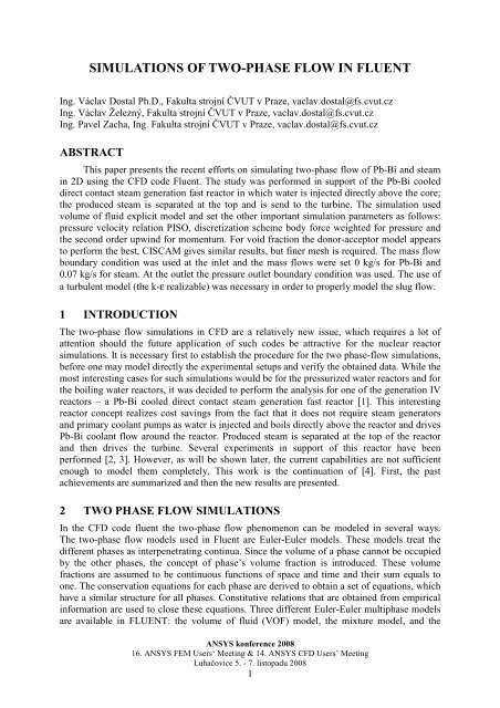
<strong>SIMULATIONS</strong> <strong>OF</strong> <strong>TWO</strong>-<strong>PHASE</strong> <strong>FLOW</strong> <strong>IN</strong> <strong>FLUENT</strong>Ing. Václav Dostal Ph.D., Fakulta strojní ČVUT v Praze, vaclav.dostal@fs.cvut.czIng. Václav Železný, Fakulta strojní ČVUT v Praze, vaclav.dostal@fs.cvut.czIng. Pavel Zacha, Ing. Fakulta strojní ČVUT v Praze, vaclav.dostal@fs.cvut.czABSTRACTThis paper presents the recent efforts on simulating two-phase flow of Pb-Bi and steamin 2D using the CFD code Fluent. The study was performed in support of the Pb-Bi cooleddirect contact steam generation fast reactor in which water is injected directly above the core;the produced steam is separated at the top and is send to the turbine. The simulation usedvolume of fluid explicit model and set the other important simulation parameters as follows:pressure velocity relation PISO, discretization scheme body force weighted for pressure andthe second order upwind for momentum. For void fraction the donor-acceptor model appearsto perform the best, CISCAM gives similar results, but finer mesh is required. The mass flowboundary condition was used at the inlet and the mass flows were set 0 kg/s for Pb-Bi and0.07 kg/s for steam. At the outlet the pressure outlet boundary condition was used. The use ofa turbulent model (the k-ε realizable) was necessary in order to properly model the slug flow.1 <strong>IN</strong>TRODUCTIONThe two-phase flow simulations in CFD are a relatively new issue, which requires a lot ofattention should the future application of such codes be attractive for the nuclear reactorsimulations. It is necessary first to establish the procedure for the two phase-flow simulations,before one may model directly the experimental setups and verify the obtained data. While themost interesting cases for such simulations would be for the pressurized water reactors and forthe boiling water reactors, it was decided to perform the analysis for one of the generation IVreactors – a Pb-Bi cooled direct contact steam generation fast reactor [1]. This interestingreactor concept realizes cost savings from the fact that it does not require steam generatorsand primary coolant pumps as water is injected and boils directly above the reactor and drivesPb-Bi coolant flow around the reactor. Produced steam is separated at the top of the reactorand then drives the turbine. Several experiments in support of this reactor have beenperformed [2, 3]. However, as will be shown later, the current capabilities are not sufficientenough to model them completely. This work is the continuation of [4]. First, the pastachievements are summarized and then the new results are presented.2 <strong>TWO</strong> <strong>PHASE</strong> <strong>FLOW</strong> <strong>SIMULATIONS</strong>In the CFD code fluent the two-phase flow phenomenon can be modeled in several ways.The two-phase flow models used in Fluent are Euler-Euler models. These models treat thedifferent phases as interpenetrating continua. Since the volume of a phase cannot be occupiedby the other phases, the concept of phase’s volume fraction is introduced. These volumefractions are assumed to be continuous functions of space and time and their sum equals toone. The conservation equations for each phase are derived to obtain a set of equations, whichhave a similar structure for all phases. Constitutive relations that are obtained from empiricalinformation are used to close these equations. Three different Euler-Euler multiphase modelsare available in <strong>FLUENT</strong>: the volume of fluid (V<strong>OF</strong>) model, the mixture model, and theANSYS konference 200816. ANSYS FEM Users‘ Meeting & 14. ANSYS CFD Users’ MeetingLuhačovice 5. - 7. listopadu 20081
Eulerian model [5]. For the higher void fraction cases, such as slug flows it is recommendedto use the V<strong>OF</strong> model. The performed experiments used high void fraction therefore the V<strong>OF</strong>is used as a primary model throughout the paper.This paper presents the results of the two-phase flow simulations of Pb-Bi and steam withdifferent mesh size and with and without the turbulence models. All the simulations wereperformed in 2D. While it is understood that two-phase flow strongly depends on all threedimensions. However, using the 2D has a big advantage in the reduced computational time,which as will be shown later is quite long. Using 2D thus allowed running more simulationsand get better feeling which mathematical models are good for modeling the two-phase flowphenomenon. Hopefully, using this knowledge it will be possible to run successfully a 3Dcase in the future.2.1 Modeling of phase interfaceThe reconstruction based schemes available in <strong>FLUENT</strong> are Geo-Reconstruct and Donor-Acceptor. The discretization schemes available with explicit scheme for V<strong>OF</strong> are First OrderUpwind, Second Order Upwind, CICSAM, Modified HRIC and QUICK.Geo-reconstruct - the geometric reconstruction scheme represents the interface betweenfluids using a piecewise-linear approach. In <strong>FLUENT</strong> this scheme is the most accurate and isapplicable for general unstructured meshes. The first step in this scheme is calculating theposition of the linear interface relative to the centre of each partially-filled cell, based oninformation about the volume fraction and its derivatives in the cell. The second step iscalculating the advecting amount of fluid through each face using the computed linearinterface representation and information about the normal and tangential velocity distributionon the face. The third step is calculating the volume fraction in each cell using the balance offluxes calculated during the previous step.Donor-acceptor – approach uses the <strong>FLUENT</strong> standard interpolation whenever a cell iscompletely filled with one phase or another. When the cell is near the interface between twophases, a "donor-acceptor" scheme is used to determine the amount of fluid advected throughthe face. This scheme identifies one cell as a donor of an amount of fluid from one phase andanother (neighbour) cell as the acceptor of that same amount of fluid, and is used to preventnumerical diffusion at the interface. The amount of fluid from one phase that can beconvected across a cell boundary is limited by the minimum of two values: the filled volumein the donor cell or the free volume in the acceptor cell.Figure 1: Examples of interphase interface calculationCompressive interface capturing scheme for arbitrary meshes (CICSAM) – this schemeis a high resolution differencing scheme and is particularly suitable for flows with high ratiosof viscosities between the phases. CICSAM is implemented in <strong>FLUENT</strong> as an explicitANSYS konference 200816. ANSYS FEM Users‘ Meeting & 14. ANSYS CFD Users’ MeetingLuhačovice 5. - 7. listopadu 20082
scheme and o offers the advantage of producing an interface that is almost as sharp as thegeometric reconstruction scheme.Modified HRIC - for simulations using the V<strong>OF</strong> multiphase model, upwind schemes aregenerally unsuitable for interface tracking because of their overly diffusive nature. Centraldifferencing schemes, while generally able to retain the sharpness of the interface, areunbounded and often give unphysical results. In order to overcome these deficiencies,<strong>FLUENT</strong> uses a modified version of the High Resolution Interface Capturing (HRIC)scheme. The modified HRIC scheme is a composite Normalized Variable Diagram (NVD)scheme that consists of a non-linear blend of upwind and downwind differencing. Themodified HRIC scheme provides improved accuracy for V<strong>OF</strong> calculations when compared toQUICK and second-order schemes, and is less computationally expensive than the Geo-Reconstruct scheme.2.2 Laminar modelingDue to the expected difficulties in the modeling the first simulations were performed withoutany turbulent model. The results of the simulation are shown in Figs. 2 and 3. Figure 2 is forthe coarse mesh with the cell size of 0.5 mm, except for the boundary layer, where 0.2 mm inthe was used. Results in Fig. 3 were obtained for a finer mesh with 0.2 mm cell size. Themeshes were formed by 990000 quads and 164178 quads respectively. The other simulationparameters were: laminar flow, explicit V<strong>OF</strong>, pressure velocity relation PISO, discretizationscheme body force weighted for pressure, second order upwind for momentum and CISCAMfor void fraction. Boundary conditions were mass flow inlet (Pb-Bi 0 kg/s and steam 0.07kg/s) and pressure outlet. The difference in simulation time arises from the difference of timestep, which has to be reduced for better convergence of the finer mesh. The running time forthese cases was on the order of 0.3 s/day for the 0.5 mm mesh and 0.1 s/day for the 0.2 mmmesh.As was already described in [4], from Figs. 1 and 2 it is apparent that the finer mesh givesresults, which are closer to the slug flow regime. The void fraction in the coarse meshdeviated more from the expected 0 or 1 behavior. This indicated that the significant number ofthe calculated bubbles were smaller than the used cell size. The large bubbles did not form atall and the results are far from the slug flow, which is against the experimental results as wellas the expectations. The finer mesh gives better results as far as void fraction is concerned.The bubbles are of larger dimension, but still smaller that in the slug flow. They have more ofa spherical shape than the typical slug flow bullet shape. The gas lift pump effect wasobserved in both cases.2.3 Turbulent modelingIn order ro obtain better results the turbulent model was used for the same analysis. The sameoperating, boundary and simulation conditions were used. The k-ε realizable turbulent modelwas used. The discretization scheme for the turbulent kinetic energy and the turbulentdissipation rate was the second order upwind scheme. The running time for these cases wasabout the same as for the laminar cases.Figures 4 and 5 show the results of the simulations (these were also already describe in [4].The benefit of using the turbulent model is clearly visible. The bullet shaped bubble withsmaller bubbles in the wake is formed. However, there is still a significant amount of cellswith the void fraction between 0 and 1 indicating the amount of smaller bubbles than the cellsize is still large. Nevertheless, the results are much better than in the case of laminar flow.The best results were achieved for the fine mesh with turbulent modeling. The bullet shapefirst bubble development is clearly visible as well as the formation of small bubbles in theANSYS konference 200816. ANSYS FEM Users‘ Meeting & 14. ANSYS CFD Users’ MeetingLuhačovice 5. - 7. listopadu 20083
wake of the large bubble. The coalescence of smaller bubbles can be observed as well. Thesecond slug-flow bubble is not as large as the first one, however the train of larger bubblesfollowed by the smaller bubbles in the wake is formed.Figure 2: Steam bubbling in Pb-Bi, cell size 0.5 mm, laminar flow, 0 – 3 s after injectionANSYS konference 200816. ANSYS FEM Users‘ Meeting & 14. ANSYS CFD Users’ MeetingLuhačovice 5. - 7. listopadu 20084
Figure 3: Steam bubbling in Pb-Bi, cell size 0.2 mm, laminar flow, 0 – 1.9 s after injectionANSYS konference 200816. ANSYS FEM Users‘ Meeting & 14. ANSYS CFD Users’ MeetingLuhačovice 5. - 7. listopadu 20085
Figure 4: Steam bubbling in Pb-Bi, cell size 0.5 mm, turbulent flow, 0 – 2 s after injectionANSYS konference 200816. ANSYS FEM Users‘ Meeting & 14. ANSYS CFD Users’ MeetingLuhačovice 5. - 7. listopadu 20086
Figure 5: Steam bubbling in Pb-Bi, cell size 0.2 mm, turbulent flow, 0 – 2 s after injectionANSYS konference 200816. ANSYS FEM Users‘ Meeting & 14. ANSYS CFD Users’ MeetingLuhačovice 5. - 7. listopadu 20087
Figure 6: X and Y velocity contours, cell size 0.2 mm, turbulent flow, at 0.9 s after injectionANSYS konference 200816. ANSYS FEM Users‘ Meeting & 14. ANSYS CFD Users’ MeetingLuhačovice 5. - 7. listopadu 20088
Figure 7 Steam bubbling in Pb-Bi, cell size 0.5 mm, turbulent flow, 0 – 3 s after injection,donor-acceptorFor the case shown in Fig. 5 the velocity contours are show in Fig. 6. The x axis is horizontaland the y axis is vertical. From the contours of the x-component of the mixture velocity onemay observe the beginning of the circulation, but more importantly one may see the s-shapeddirection of flow behind the first bullet shaped bubble. It is indicated by the alternatingregions of the positive and negative x-component of the mixture velocity, which suggest thealternation of the flow direction. The y-component of the mixture velocity, i.e. the verticalmixture velocity component, is more interesting. It shows the flow paths of the rising steamand the downward flow of Pb-Bi around the bubbles, especially close to the wall.The results with the different volume fraction dicretization scheme are shown in Fig. 7. In thissimulation the donor-acceptor dicretization scheme was used. The results are similar to whatwas seen in Fig. 5 for CISCAM and 0.2mm cell size mesh. However, for the donor-acceptorscheme the coarser mesh was used and therefore the computational time was significantlyreduced. This case was run for longer time and therefore also the under carry of the bubbles inANSYS konference 200816. ANSYS FEM Users‘ Meeting & 14. ANSYS CFD Users’ MeetingLuhačovice 5. - 7. listopadu 20089
the downcomer could be observed. Even though not many bubbles actually reached thebottom this phenomenon could bring the problem of core voiding and associated reactivityfeedbacks in the real nuclear reactor case.3 CONCLUSIONSA two-phase flow simulation of Pb-Bi and steam using a CFD code Fluent was performed.The incorporation of the turbulent model (k-ε realizable), when compared to the laminar flow,resulted in larger bubbles and formation of the bullet shaped first bubble typical for the slugflow, which was observed in the experiments. The incorporation of the turbulent model didnot result in the significant increase in the simulations’ computational time. When theCISCAM void fraction discretization scheme was used, the results of the simulations revealedthat a very fine mesh with cell size on the order of 0.2 mm is necessary. Such mesh producedresults close to the slug flow. It resulted in larger bubbles and reduced the amount of bubblessmaller that the cell size. The simulations using such a fine mesh turned out to becomputationally quite intense. The donor-acceptor void fraction discretization scheme withthe cell size of 0.5 mm achieved even better results than the CISCAM discretization schemewith finer mesh at much shorter times and therefore appears to be more favorable.ACKNOWLEDGEMENTSThis work was funded from the Research Plan: Safety of Nuclear InstallationsMSM6840770020. The support is gratefully acknowledged.REFERENCES[1] Takahashi M., Obara T., Iguchi T., et al. (2004), Design and Experimental Study forDevelopment of Pb-Bi Cooled Direct Contact Boiling Water Small Fast Reactor(PBWFR). Proc. of Int. Conf. on Advanced Power Plants (ICAPP), p.4058 Pittsburgh,13-17 Jun.[2] Akashi T., Takahashi M., “Study on Pb-Bi-Steam Two-Phase Flow for Evaluation ofLift Pump Performance in PBWFR,” 12th International Conference on NuclearEngineering (ICONE12), Arlington, Virginia, USA, April 25-29, (2004).[3] M. Takahashi, et al., “Study on Pb-Bi-Water Direct Contact Boiling Two-Phase Flowand Heat Transfer”, Progress in Nucl. Energy, Vol.47, No.1-4, January-April 2005. pp.569-576[4] Dostal V., Zelezny V., Zacha P.,” CFD Simulations of Pb-Bi Two-Phase Flow”,International Youth Nuclear Congress 2008 (IYNC 2008), Interlaken , Switzerland,September 20 – 26, (2008), paper no. 249[5] Fluent 6.3 User’s Guide, September, (2006)ANSYS konference 200816. ANSYS FEM Users‘ Meeting & 14. ANSYS CFD Users’ MeetingLuhačovice 5. - 7. listopadu 200810