Wave experiments using low-cost 40 kHz ultrasonic transducers
Wave experiments using low-cost 40 kHz ultrasonic transducers
Wave experiments using low-cost 40 kHz ultrasonic transducers

You also want an ePaper? Increase the reach of your titles
YUMPU automatically turns print PDFs into web optimized ePapers that Google loves.
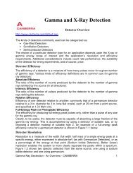
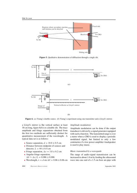
Mak Se-yuenRegions where secondary maximaand minima can be detectedTransmitterReceiverFixed ruleTo CROTo SGSliding ruleFigure 5. Qualitative demonstration of diffraction through a single slit.To SGdPair oftransmittersLReceiverTo CRO(a)TransmitterTo SGd/2LReceiverTo CROImage oftransmitterVertical reflector as Lloyd’s mirror(b)Figure 6. (a) Young’s double source. (b) Young’s experiment <strong>using</strong> one transmitter and a Lloyd’s mirror.a Lloyd’s mirror (a flat vertical surface at least30 cm long, figure 6(b)) or a double slit. The traceamplitude and fringe separations obtained fromthe first two methods are sufficiently distinct forquantitative measurement of the wavelength. Atypical data set is as fol<strong>low</strong>s:• Source separation, d = 10.0 ± 0.5cm• Distance between midpoint of sources anddetector, L = 44 ± 0.4 cm• Fringe separation, x = 3.8 ± 0.2 cm• Angular fringe separation,θ ≈ x/L = 0.086 ± 0.006• <strong>Wave</strong>length, λ = d sin θ = 0.86 ± 0.06 cmAmplitude modulationAmplitude modulation can be done if the outputtransducer is driven by a signal generator equippedwith such a function. The transmitted range is overa metre when a CRO is used to display a periodicmodulated signal, but limited to only a fewcentimetres if a <strong>low</strong>-power amplifier–loudspeakeris used to play music.Music transmitted by a waveguideThe range of audio-signal transmission can beincreased to about 1.0 m by feeding the ultrasoundwave into one end of a 1.5 cm bore air-pipe with444 P HYSICS E DUCATION September 2003