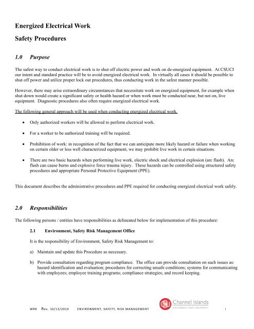
Energized Electrical Work Safety Procedures
Energized Electrical Work Safety Procedures
Energized Electrical Work Safety Procedures

Create successful ePaper yourself
Turn your PDF publications into a flip-book with our unique Google optimized e-Paper software.
Table 1: Approach Boundaries to Live Parts for Shock ProtectionVoltage RangePhase to PhaseExposed MovableConductorLimited ApproachExposed FixedCircuit PartRestrictedApproachProhibitedApproachLess than 50 Not Specified Not Specified Not Specified Not Specified50 to 300 10 feet 0 inches 3 feet 6 inches Avoid Contact Avoid Contact301 to 750 10 feet 0 inches 3 feet 6 inches 1 foot 0 inches 0 feet 1 inch751 to 15 kV 10 feet 0 inches 5 feet 0 inches 2 feet 2 inches 0 feet 7 inches15.1 kV to 36 kV 10 feet 0 inches 6 feet 0 inches 2 feet 7 inches 0 feet 10 inches36.1 kV to 46 kV 10 feet 0 inches 8 feet 0 inches 2 feet 9 inches 1 foot 5 inchesMultiply single phase voltages by 1.73 to obtain correct voltage level to be used for table (NFPA 70E C.2.11)Limited Approach BoundaryRestricted Approach BoundaryProhibited Approach BoundaryProhibited SpaceRestricted SpaceLimited SpaceWRK Rev. 10/13/2010 ENVIRONMENT, SAFETY, RISK MANAGEMENT 6
6 <strong>Work</strong>ing On or Near Live Parts6.2 Justification for <strong>Work</strong>.Live parts to which an employee might be exposed shall be put into an electrically safe work condition before anemployee works on or near them, unless the employer can demonstrate that de-energizing introduces additional orincreased hazards or is infeasible due to equipment design or operational limitations. <strong>Energized</strong> parts that operate atless than 50 volts to ground shall not be required to be de-energized if there will be no increased exposure to electricalburns or to explosion due to electric arcs.Examples of increased or additional hazards include, but are not limited to, interruption of life support equipment,deactivation of emergency alarm systems, and shutdown of hazardous location ventilation equipment.Examples of work that might be performed on or near exposed energized electrical conductors or circuit partsbecause of infeasibility due to equipment design or operational limitations include performing diagnostics and testing(e.g., start-up or troubleshooting) of electric circuits that can only be performed with the circuit energized and workon circuits that form an integral part of a continuous process that would otherwise need to be completely shut down inorder to permit work on one circuit or piece of equipment.7.2 <strong>Energized</strong> <strong>Electrical</strong> <strong>Work</strong> Permit(1) Where Required. If live parts are not placed in an electrically safe work condition (i.e., for the reasons ofincreased or additional hazards or infeasibility per 7.1), work to be performed shall be considered energizedelectrical work and shall be performed by written permit only.(2) Elements of <strong>Work</strong> Permit. The energized electrical work permit shall include the following items:(1) A description of the circuit and equipment to be worked on and their location(2) Justification for why the work must be performed in an energized condition(3) A description of the safe work practices to be employed(4) Results of the shock hazard analysis(5) Determination of shock protection boundaries(6) Results of the flash hazard analysis(7) The Flash Protection Boundary(8) The necessary personal protective equipment to safely perform the assigned task(9) Means employed to restrict the access of unqualified persons from the work area(10) Evidence of completion of a job briefing, including a discussion of any job-specific hazards(11) <strong>Energized</strong> work approval signatures (responsible supervisor, or OPC manager).Exemptions to <strong>Work</strong> Permit. <strong>Work</strong> performed on or near live parts by qualified persons related to tasks such astesting, troubleshooting, voltage measuring, etc., shall be permitted to be performed without an energizedelectrical work permit, provided appropriate safe work practices and personal protective equipment in accordancewith this procedure are provided and used.7.3 Flash Hazard AnalysisA flash hazard analysis shall be done in order to protect personnel from the possibility of being injured by an arcflash. The analysis shall determine the Flash Protection Boundary and the personal protective equipment thatpeople within the Flash Protection Boundary shall use.WRK Rev. 10/13/2010 ENVIRONMENT, SAFETY, RISK MANAGEMENT 7
(2) Obstructed View of <strong>Work</strong> Area. Where lack of illumination or an obstruction precludes observation ofthe work to be performed, employees shall not perform any task near live parts operating at 50 volts or moreor where an electrical hazard exists.(D) Conductive Articles BeingWorn. Conductive articles of jewelry and clothing (such as watchbands,bracelets, rings, key chains, necklaces, metalized aprons, cloth with conductive thread, metal headgear, or metalframe glasses) shall not be worn where they present an electrical contact hazard with exposed live parts.(E) Conductive Materials, Tools, and Equipment Being Handled.(1) General. Conductive materials, tools, and equipment that are in contact with any part of anemployee’s body shall be handled in a manner that prevents accidental contact with live parts. Suchmaterials and equipment include, but are not limited to, long conductive objects, such as ducts, pipes andtubes, conductive hose and rope, metal-lined rules and scales, steel tapes, pulling lines, metal scaffoldparts, structural members, bull floats, and chains.(2) Approach to Live Parts. Means shall be employed to ensure that conductive materials approachexposed live parts no closer than that permitted by Table 1.(F) Confined or Enclosed <strong>Work</strong> Spaces. When an employee works in a confined or enclosed space (such as amanhole or vault) that contains exposed live parts operating at 50 volts or more or an electrical hazard exists, theemployer shall provide, and the employee shall use, protective shields, protective barriers, or insulating materialsas necessary to avoid inadvertent contact with these parts. Doors, hinged panels, and the like shall be secured toprevent their swinging into an employee and causing the employee to contact exposed live parts operating at 50volts or more or where an electrical hazard exists.(G) Housekeeping Duties. Where live parts present an electrical contact hazard, employees shall not performhousekeeping duties inside the Limited Approach Boundary where there is a possibility of contact, unlessadequate safeguards (such as insulating equipment or barriers) are provided to prevent contact. <strong>Electrical</strong>lyconductive cleaning materials (including conductive solids such as steel wool, metalized cloth, and siliconecarbide, as well as conductive liquid solutions) shall not be used inside the Limited Approach Boundary unlessprocedures to prevent electrical contact are followed.(H) Occasional Use of Flammable Materials. Where flammable materials are present only occasionally, electricequipment capable of igniting them may not be used, unless measures are taken to prevent hazardous conditionsfrom developing. Such materials include, but are not limited to, flammable gases, vapors, or liquids; combustibledust; and ignitible fibers or flyings.(I) Anticipating Failure. When there is evidence that electric equipment could fail and injure employees, theelectric equipment shall be de-energized unless the employer can demonstrate that de-energizing introducesadditional or increased hazards or is infeasible because of equipment design or operational limitation. Until theequipment is de-energized or repaired, employees shall be protected from hazards associated with the impendingfailure of the equipment.(J) Routine Opening and Closing of Circuits. Load-rated switches, circuit breakers, or other devicesspecifically designed as disconnecting means shall be used for the opening, reversing, or closing of circuits underload conditions. Cable connectors not of the load-break type, fuses, terminal lugs, and cable splice connectionsshall not be permitted to be used for such purposes, except in an emergency.(K) Reclosing Circuits After Protective Device Operation.After a circuit is de-energized by a circuit protective device, the circuit shall not be manually reenergized until ithas been determined that the equipment and circuit can be safely energized. The repetitive manual reclosing ofcircuit breakers or reenergizing circuits through replaced fuses shall be prohibited. When it is determined from thedesign of the circuit and the overcurrent devices involved that the automatic operation of a device was caused byan overload rather than a fault condition, examination of the circuit or connected equipment shall not be requiredbefore the circuit is reenergized.WRK Rev. 10/13/2010 ENVIRONMENT, SAFETY, RISK MANAGEMENT 13
TABLE 2 (CONTINUED)Task (Assumes Equipment Is <strong>Energized</strong>, and <strong>Work</strong>Is Done Within the Flash Protection Boundary)Hazard / RiskCategoryV-RatedGlovesV-RatedToolsNEMA E2 (fused contactor) Motor Starters, 2.3 KvThrough 7.2 kVContactor operation with enclosure doors closed 0 N NReading a panel meter while operating a meter switch 0 N NContactor operation with enclosure doors open 2* N N<strong>Work</strong> on energized parts, including voltage testing 3 Y Y<strong>Work</strong> on control circuits with energized parts 120 V orbelow, exposed0 Y Y<strong>Work</strong> on control circuits with energized parts >120 V,exposed3 Y YInsertion or removal (racking ) of starters from cubicles,doors open3 N NInsertion or removal (racking) of starters from cubicles,doors closed2 N NApplication of safety grounds, after voltage test 3 Y NRemoval of bolted covers (to expose bare, energized parts) 4 N NOpening hinged covers (to expose bare, energized parts) 3 N NMetal Clad Switchgear, 1 kV and AboveCB or fused switch operation with enclosure doors closed 2 N NReading a panel meter while operating a meter switch 0 N NCB or fused switch operation with enclosure doors open 4 N N<strong>Work</strong> on energized parts, including voltage testing 4 Y Y<strong>Work</strong> on control circuits with energized parts 120 V orbelow, exposed2 Y Y<strong>Work</strong> on control circuits with energized parts >120 V,exposed4 Y YInsertion or removal (racking ) of CBs from cubicles, doorsopen4 N NInsertion or removal (racking) of CBs from cubicles, doorsclosed2 N NApplication of safety grounds, after voltage test 4 Y NRemoval of bolted covers (to expose bare, energized parts) 3 N NOpening hinged covers (to expose bare, energized parts) 3 N NOpening voltage transformer or control power transformercompartments4 N NWRK Rev. 10/13/2010 ENVIRONMENT, SAFETY, RISK MANAGEMENT 16
TABLE 2 (CONTINUED)Task (Assumes Equipment Is <strong>Energized</strong>, and <strong>Work</strong>Is Done Within the Flash Protection Boundary)Hazard / RiskCategoryV-RatedGlovesV-RatedToolsOther Equipment 1 kV and AboveMetal clad load interrupter switches, fused or unfused -- -- --Switch operation, doors closed 2 N N<strong>Work</strong> on energized parts, including voltage testing 4 Y YRemoval of bolted covers (to expose bare, energized parts) 4 N NOpening hinged covers (to expose bare, energized parts) 3 N NOutdoor disconnect switch operation (hookstick operated) 3 Y YOutdoor disconnect switch operation (gang-operated, fromgrade)2 N NInsulated cable examination, in manhole or other confined4 Y NspaceInsulated cable examination, in open area 2 Y NNote:V-rated Gloves are gloves rated and tested for the maximum line-to-line voltage upon which work will be done.V-rated Tools are tools rated and tested for the maximum line-to-line voltage upon which work will be done.2* means that a double-layer switching hood and hearing protection are required for this task in addition to the other Hazard/Risk Category 2 requirements ofTable 130.7(C)(10).Y = yes (required)N = no (not required)Notes:1. 25 kA short circuit current available, 0.03 second (2 cycle) fault clearing time.2. 65 kA short circuit current available, 0.03 second (2 cycle) fault clearing time.3. For 10 kA short circuit current available, the hazard/risk category required may be reduced by one number.4. 65 kA short circuit current available, 0.33 second (20 cycle) fault clearing time.5. 65 kA short circuit current available, up to 1.0 second (60 cycle) fault clearing time.6. For 25 kA short circuit current available, the hazard/risk category required may be reduced by one number.WRK Rev. 10/13/2010 ENVIRONMENT, SAFETY, RISK MANAGEMENT 17
TABLE 4PROTECTIVE CLOTHING CHARACTERISTICSTYPICAL PROTECTIVE CLOTHING SYSTEMSHazard / RiskCategoryClothing Description(Typical number of clothing layers is given in parentheses)Required Minimum ArcRating of PPE[J/cm 2 (cal/cm 2 )]0 Non-melting, flammable materials (i.e., untreated cotton, wool,rayon, or silk, or blends of these materials) with a fabric weightat least 4.5 oz/yd2 (1)N/A1 FR shirt and FR pants or FR coverall (1) 16.74 (4)2 Cotton underwear — conventional short sleeve and brief/shorts,plus FR shirt and FR pants (1 or 2)3 Cotton underwear plus FR shirt and FR pants plus FR coverall, orcotton underwear plus two FR coveralls (2 or 3)4 Cotton underwear plus FR shirt and FR pants plus multilayerflash suit (3 or more)33.47 (8)104.6 (25)167.36 (40)Note: Arc rating is defined in Article 100 and can be either ATPV or E BT . ATPV is defined in ASTM F 1959-99 as the incident energy on a fabric or materialthat results in sufficient heat transfer through the fabric or material to cause the onset of a second-degree burn based on the Stoll curve. E BT is defined in ASTMF 1959-99 as the average of the five highest incident energy exposure values below the Stoll curve where the specimens do not exhibit breakopen. E BT isreported when ATPV cannot be measured due to FR fabric breakopen.WRK Rev. 10/13/2010 ENVIRONMENT, SAFETY, RISK MANAGEMENT 19
APPENDIX AENERGIZED ELECTRICAL WORK PERMIT FORMPart I: TO BE COMPLETED BY THE ELECTRICALLY QUALIFIED PERSON DOING THE WORK:<strong>Work</strong> Order Number: ________________________________1) Description of circuit:____________________________________________________________________________Name of equipment:_______________________________________Identification:____________________________________________Location:________________________________________________Fed from:________________________________________________2) Description of work to be done:___________________________________________________________________________________________________________________________________________________________________3) Justification of why the circuit/equipment cannot be de-energized or the work deferred until the next scheduled outage:____________________________________________________________________________________________________________________________________________________________________________________________4) Shock Hazard Analysis<strong>Electrical</strong> energy source hazards (check all that apply)[ ] Less than 50 volts [ ] 277 volts [ ] Emergency power[ ] 120 volts [ ] 480 volts [ ] Remote control ____________________________[ ] 208 volts [ ] 600 volts [ ] DC _____________________________________[ ] 240 volts [ ] other (describe) _________ [ ] Foreign __________________________________5) Determination of Shock Protection Boundaries (Table 1):______________________________________________________6) Determination of the Flash Protection Boundary (see 7.3):________________________________________________Flash Protection Boundary (check method used)[ ] 4.0 feet (systems less than 600 volts, with 0.1 sec clearing time, Ibf < 50kA or 5000 A-sec)[ ] Physical boundaries of the substation or enclosure (for systems > 600 volts)[ ] Other – contact electric shop for assistance _______________________________________7) Results of the Flash Hazard Analysis (If no flash hazard calculation, go to #8 below and use alternate procedures):Incident Energy:_______ Arc rating of PPE:________WRK Rev. 10/13/2010 ENVIRONMENT, SAFETY, RISK MANAGEMENT 20
8) Alternate procedures to detailed flash hazard analysis for selection of PPE (section 7.4):8a) Voltage__________ Short Circuit current capacity _______________________Fault clearing device (name) _____________________(description)________________________________Manufacturers Model or type number ___________________________Fault clearing time (seconds) __________________________________8b) Hazard/Risk Category (Table 2) _______8c) Protective clothing (Table 3) _____________________________________________________________________________________________________________________________________________________________8c) Other PPE (rated gloves, tools etc)________________________________________________________________________________________________________________________________________________________________________________________9) Means employed to restrict access by unqualified persons:[ ] Locked access [ ] <strong>Safety</strong> Watch Required[ ] Barrier tape/ stanchions[ ] <strong>Electrical</strong> Hazard Signs [ ] Other means to restrict access (describe) _____________________________________________________________________________________________________________________________Part II: APPROVAL TO PERFORM WORK WHILE ELECTRICALLY ENERGIZED:____________________________________________ _____________________________ _________________Name of electrically qualified person performing work Signature Date____________________________________________ _____________________________ _________________Name of electrically qualified person performing work Signature DateWRK Rev. 10/13/2010 ENVIRONMENT, SAFETY, RISK MANAGEMENT 21
APPENDIX BSIMPLIFIED, TWO-CATEGORY, FLAME RESISTANT CLOTHING SYSTEM(NFPA 70E ANNEX H)Table B.1 can be used as a simplified approach to assure adequate PPE for electrical workers on campus. The clothing listed in TableB.1 fulfills the minimum FR clothing requirements of Table 3 and Table 4. The clothing systems listed in this table should be usedwith the other PPE appropriate for the Hazard / Risk Category (see Table 4).Table B.1 Simplified, Two-Category, Flame-Resistant Clothing SystemCLOTHING*APPLICABLE TASKEveryday <strong>Work</strong> ClothingFR long-sleeve shirt (minimum arc rating of 4) worn overan untreated cotton T-shirt with FR pants (minimum arcrating of 8)orFR coveralls (minimum arc rating of 4) worn over anuntreated cotton T-shirt (or an untreated natural fiberlong-sleeve shirt) with untreated natural fiber pants.All Hazard/Risk Category 1 and 2 tasks listed in Table 3.On systems operating at less than 1000 volts, these tasksinclude work on all equipmentexcept –• Insertion or removal of low-voltage motor starter“buckets”• Insertion or removal of power circuit breakersfrom switchgear cubicles or• Removal of bolted covers from switchgearOn systems operating at 1000 volts or greater, tasks alsoinclude the operation of switching devices with theequipment enclosure doors closed.<strong>Electrical</strong> “Switching ClothingMultilayer FR flash jacket and FR bib overalls worn overeither FR coveralls (minimum arc rating of 4) or FR longsleeveshirt and FR pants (minimum arc rating of 4), wornover untreated natural fiber long-sleeve shirt and pants,worn over an untreated cotton T-shirtOrInsulated FR coveralls (with a minimum arc rating of 25,independent of other layers) worn over untreated naturalfiber long-sleeve shirt with untreated denim cotton bluejeans (“regular weight,” minimum 12 oz/yd fabricweight), worn over an untreated cotton T-shirt.All Hazard / Risk Category 3 and 4 tasks listed in Table 3.On systems operating at 1000 volts or greater, these tasksinclude work on exposed live parts of all equipment.On systems of less than 1000 volts, tasks include insertionor removal of low-voltage motor starter MCC “buckets,”insertion or removal of plug-in devices into or frombusway, insertion or removal of power circuit breakers andremoval of bolted covers from switchgear.* Note other PPE required for the specific tasks listed in Table 2 and Table 3, which include arc-rated face shields or flash suit hoods,FR hardhat liners, safety glasses or safety goggles, hard hat, hearing protection, leather gloves, voltage-rated gloves, and voltage-ratedtools.WRK Rev. 10/13/2010 ENVIRONMENT, SAFETY, RISK MANAGEMENT 22