Matrix User Guide - Interprovincial Traffic Services
Matrix User Guide - Interprovincial Traffic Services
Matrix User Guide - Interprovincial Traffic Services

Create successful ePaper yourself
Turn your PDF publications into a flip-book with our unique Google optimized e-Paper software.
ContentsIntroduction 5SmartSensor <strong>Matrix</strong> Package 6 • Selecting a MountingLocation 7Part IInstalling the SmartSensor <strong>Matrix</strong>Chapter 1 Installing the SmartSensor <strong>Matrix</strong> 13Sensor Mounting <strong>Guide</strong>lines 14 • Attaching the MountBracket to the Pole 14 • Attaching the Sensor to the MountBracket 15 • Aligning the Sensor to the Roadway 16 •Applying the Silicon Dielectric Compound 17 • Connectingthe SmartSensor 6-conductor Cable 18 • Grounding theSensor 19Chapter 2 Connecting Power and Surge Protection 21Mounting the Backplate 22 • Connecting AC Power 22• Providing System Surge Protection 26 • TerminatingSmartSensor 6-conductor Cables 28Chapter 3 Contact Closure Communication 31Using the Click 112/114 DIP Switches 32 • Using the Click104 Rotary Switch 34 • Attaching and Programming theClick 112/114 35 • Attaching and Programming the Click104 37 • Channel Mapping 39
6 INTRODUCTION • SMARTSENSOR MATRIX USER GUIDEration process is quick and easy. After installation, the sensor will require little or no on-sitemaintenance and can be remotely configured.This user guide outlines the step-by-step process of installing and configuring the Smart-Sensor <strong>Matrix</strong>. Any questions about the information in this guide should be directed toWavetronix or your distributor.SmartSensor <strong>Matrix</strong> PackageA standard SmartSensor <strong>Matrix</strong> package may contain the following items:˽˽˽˽˽˽˽˽˽˽˽˽˽˽˽˽SmartSensor <strong>Matrix</strong> SS225 detector(s) with installed sensor backplateSensor mounting kit(s)SmartSensor 6-conductor cable(s)Intersection Preassembled BackplateClick 112/114 detector rack card(s) with patch cable(s)Click 104 four-channel DIN rail contact closure moduleSmartSensor Manager <strong>Matrix</strong> (SSMM) softwareSmartSensor <strong>Matrix</strong> <strong>User</strong> <strong>Guide</strong>SmartSensor <strong>Matrix</strong> system options include (see Figure I.2):˽˽˽˽˽˽AC power conversion – Provides reliable power for the sensors and backplate components.This option is normally recommended instead of the DC surge protectionbecause it will not burden the existing DC power modules.Wavetronix Install Kit – Provides both wired and wireless configuration capability usinga handheld computer and a Click 421 Bluetooth® to serial converter. The handheldcomputer comes pre-loaded with SmartSensor Manager <strong>Matrix</strong> and Click Supervisorsoftware, as well as the SmartSensor Manager programs for the other Wavetronixsensors.Remote IP connection – Provides a way (via a Click 301 serial to Ethernet converter)to connect to the sensor from a remote location. The Click 301 is recommended forremote management.
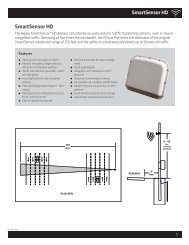
INTRODUCTION • SMARTSENSOR MATRIX USER GUIDE 7Control Bridge to Rack CardsAC PowerConversionOptionControl Bridgeon T-busConfiguration Toolkit(attach to T-bus)Control Bridge to Sensors Remote IP Connection Option(attach to T-bus)Figure I.2 – SmartSensor <strong>Matrix</strong> System OptionsNoteSmartSensor <strong>Matrix</strong> systems provide a control bridge to manage all connectedSmartSensor and Click devices. The control bridge is completely separate from thededicated channels used for communication of contact closure detection calls in realtime.Selecting a Mounting LocationConsider the following guidelines when selecting a mounting location for each SmartSensor<strong>Matrix</strong>:˽˽Corner radar – The SmartSensor <strong>Matrix</strong> is a corner radar device with a panoramic90°, 140-ft. (42.7-m) view (see Figure I.3). The sensor’s mounting location shouldbe selected so that all stop bar detection zones on an approach are within a 6–140-ft.(1.8–42.7-m) radial distance.
8 INTRODUCTION • SMARTSENSOR MATRIX USER GUIDE140 ftSensor Pole140 ftFigure I.3 – Corner Radar˽˽˽˽˽˽˽˽˽˽˽˽˽˽˽˽˽˽˽˽Line of sight – Position the sensor so that it will be able to detect the entire areaof interest. Avoid occlusion by installing the sensor away from trees, signs and otherroadside structures.Detection coverage – Position the sensor so that it will be able to reach all the specifiedstop bar detection zones. The sensor will often work better if you position it so that ittracks vehicles for several feet before the first zone in each lane. If the sensor has a viewseveral feet beyond the stop bar, it is more likely to accurately detect queue dissipation.Closest roadside – Mount the sensor on the side of the road closest to the lanes ofprimary interest. Always mount the sensor high enough to prevent traffic from occludingapproaching vehicles.Mounting height – A minimum height of 12 ft. (3.6 m) is recommended. Mountingthe sensor higher will generally improve line of sight and decrease the possibility ofocclusion.Mounting offset – A minimum offset of 6 ft. (1.8 m) to the first lane of interest isrequired.Redundant detection – It is possible to have multiple sensors monitoring the sameapproach. Multiple sensors are needed when zones are spread over more than 140 ft.(42.7 m).Sensor proximity – When multiple sensors are mounted at the same intersection,interference can be avoided by configuring each sensor to operate on a unique RFchannel.Departing lanes – There is usually no need to view traffic in departing lanes or toconfigure departing lanes. However, if they are configured, then the stop bar shouldnot be configured.Suspended electrical cables – The sensor is designed to work in the presence of suspendedpower lines and other electrical cables. However, these cables should be at least10 ft. (3 m) away from the front of the sensor.Neighboring structures and parallel walls – The sensor should not be mounted with
INTRODUCTION • SMARTSENSOR MATRIX USER GUIDE 9˽˽signs or other flat surfaces directly behind it. This will help reduce multiple reflectionpaths from a single vehicle.Cable length – Make sure that you have sufficient homerun and sensor cabling. Cableruns as long as 500 ft. (152.4 m) can be achieved using 24 VDC operation and thesystem’s native RS-485 communications. If your application requires a cable lengthlonger than 500 ft. (152.4 m), contact Wavetronix Technical <strong>Services</strong> for assistance.The SmartSensor <strong>Matrix</strong> should be mounted using one of the following options (see FigureI.4):➋➊➌Figure I.4 – Mounting locations1 The back side of mast arm – This location allows the sensor to be placed near the lanesof interest and may be the best location option for wide approaches. If you mount thesensor on the back side of a mast arm, mount it near the end of the arm to reduce thepossibility of the mast arm or departing traffic occluding approaching vehicles.2 The far side of approach – The sensor is usually mounted on a corner vertical mastpole or strain pole. If the sensor is mounted on a vertical pole with a mast arm, youcan usually avoid occlusion by mounting the sensor away from or below the mast arm.3 The near side of approach – This mounting location is typically best if detecting theleft turn lane is less important. This location also allows you to mount the sensor highenough to avoid occlusion.Other mounting locations may be possible if these are not available at your intersection.Contact Wavetronix Technical <strong>Services</strong> for assistance if you would like to use an alternativemounting location.
Installing the SmartSensor <strong>Matrix</strong> 1In this chapter˽˽Sensor Mounting <strong>Guide</strong>lines˽˽Attaching the Mount Bracket to the Pole˽˽Attaching the Sensor to the Mount Bracket˽˽Aligning the Sensor to the Roadway˽˽Applying the Silicon Dielectric Compound˽˽Connecting the SmartSensor 6-conductor Cable˽˽Grounding the Sensor1The installation process includes attaching the mounting bracket to the pole; attaching thesensor to the mounting bracket; aligning the sensor; applying a silicon dielectric compoundto the sensor connector; and connecting the SmartSensor 6-conductor cable to the sensor.CautionDo not attempt to service or repair this unit. This unit does not contain any componentsand/or parts serviceable in the field. Any attempt to open this unit, except asexpressly written and directed by Wavetronix, will void the customer warranty. Wavetronixis not liable for any bodily harm or damage caused if service is attemptedor if the back cover of the SmartSensor unit is opened. Refer all service questions toWavetronix or an authorized distributor.
14 CHAPTER 1 • INSTALLING THE SMARTSENSOR MATRIXWarningUse caution when installing any sensor on or around active roadways. Serious injurycan result when installation is performed using methods that are not in accordancewith authorized local safety policy and procedures. Always maintain an appropriateawareness of the traffic conditions and safety procedures as they relate to specificlocations and installations.Sensor Mounting <strong>Guide</strong>linesThe sensor is fairly insensitive to mounting height, but every site will vary based on laneconfiguration and the presence of barriers and structures in and around the detection area.The following table will help you determine how high to mount the sensor (see Table 1.1).These figures are only suggestions, but a good rule to follow is—the farther away the firstlane is to the sensor, the higher you will want to mount the sensor to avoid occlusion.Closest Lane Sensor Height6–15 feet 12–25 feet15–50 feet 15–25 feet> 50 feet 25–60 feetTable 1.1 – Suggested Mounting <strong>Guide</strong>linesNoteIn certain conditions, lanes that have stop bars or detection zones placed at extendedrange may show some loss in performance, even with a proper mounting height.This is more apparent at locations with many travel lanes or where detection zonesare placed near the far edges of detection. If you have any questions regarding theuse of SmartSensor <strong>Matrix</strong> at a particular location, please contact Wavetronix Technical<strong>Services</strong> or your authorized Wavetronix dealer for more information.Use the following guidelines to determine the best mounting height, then place your sensoraccordingly:˽˽In general, the sensor should be placed at a height of roughly 20 ft. (6.1 m), give ortake 5 ft. (±1.5 m).˽˽The maximum recommended mounting height for the SmartSensor <strong>Matrix</strong> is 60 ft.(18.2 m). The minimum is 12 ft. (3.6 m). Placing the sensor above or below these limitswill adversely affect detection accuracy.
CHAPTER 1 • INSTALLING THE SMARTSENSOR MATRIX 15˽˽˽˽˽˽˽˽Take into consideration the sensor’s field of view, which reaches 140 ft. (42.7 m) fromthe sensor. Place the sensor so that the field of view covers all the areas of interest.The mast arm is frequently a good place to mount the sensor.The mounting position should have a clear view of the detection area. Poles, mast arms,signal heads, or other objects should not block the view of the detection area.Placing the sensor higher will result in less occlusion. Placing it lower could result inmore occlusion. However, if the nearest detection area is less than about 20 ft. (6.1 m)away, the sensor may perform better with a lower mounting position.NoteIt is possible to mount the sensor lower than 12 ft. (3 m) in some scenarios. Thesensor will continue to detect vehicles at lower heights, but missed detections dueto occlusion may become more prevalent or problematic in lanes that are fartheraway from the sensor.Attaching the Mount Bracket to the PoleBefore attaching the mount bracket to the pole, first make sure that your cables are long enoughto reach the sensor height and to stretch across the distance from the sensor to the cabinet.Follow the steps below to correctly attach the mount to the pole:1 Insert the stainless steel straps through the slots in the mount bracket.2 Position the mount on the pole so that the head of the mount is pointing toward thelanes of interest at about a 45° angle.3 Tighten the strap screws.Figure 1.1 – Attach the Mount Bracket to the PoleThe sensor double-swivel mount may need to be adjusted later to fine-tune the alignment.
16 CHAPTER 1 • INSTALLING THE SMARTSENSOR MATRIXOne swivel joint is used to pan the sensor field of view left or right and the other swiveljoint is used to tilt the sensor down towards the roadway. If you are not using the doubleswivel-mount, make sure the pole straps are adjustable at this point in the installationprocess.Attaching the Sensor to the Mount BracketUse the following steps to securely fasten the sensor to the mount bracket:1 Align the bolts on the sensor’s backplate with the holes in the mount bracket. Theeight-pin connector receptacle on the bottom of the sensor should be pointing towardsthe ground.2 Place the lock washers onto the bolts after the bolts are in the mount bracket holes.3 Thread on the nuts and tighten (see Figure 1.2)Figure 1.2 – Attach the Sensor to the Mount BracketCautionDo not over-tighten the fasteners.Aligning the Sensor to the RoadwayThe sensor’s beams fan out 45° to the left and 45° to the right, creating a 90° corner radarfield of view. In most applications, you will want to position the corner radar so that its 90°footprint covers all lanes approaching the stop bar (see Figure 1.3).
CHAPTER 1 • INSTALLING THE SMARTSENSOR MATRIX 1745°45°Pan sensortowards stop barEdge of first lane of interestStop BarFigure 1.3 – Corner Radar Field of View PositionTo visualize the extent of the sensor field of view, the 90° field of view is imprinted on thetop and bottom of the sensor case. If more of a visual indicator is needed, then a squareframing tool (e.g. rafter square) or other tool with a right angle can be held above thesensor. By looking down both edges of the tool, you can visualize the extent of the radar’scoverage.Usually the front edge of the sensor’s field of view is aligned to provide coverage beyondthe stop bar (see Figure 1.4). This allows you to place detection zones beyond the stop barto detect those vehicles that do not stop at or behind the stop line and will also allow thesensor to see vehicles exiting queues. If the sensor pole is upstream from the stop bar, it isrecommended to pan in the direction of the stop bar.Front edge of field of viewFigure 1.4 – Sensor Aligned by Rotating Towards the Stop BarUse the following steps to correctly align the SmartSensor <strong>Matrix</strong>:
18 CHAPTER 1 • INSTALLING THE SMARTSENSOR MATRIX1 Adjust the side-to-side angle so that the front edge of the field of view provides a viewdownstream of the stop bar.2 Tilt the sensor down so it is aimed at the center of the lanes of interest.3 If necessary, rotate the sensor so that the bottom edge of the sensor is parallel withthe roadway. This is necessary where the intersection approach has a significant grade.NoteTo fully complete sensor alignment, you will need to connect to the <strong>Matrix</strong> sensorusing SmartSensor Manager <strong>Matrix</strong> and verify that your alignment is detecting thevehicles in the lanes of interest (see Chapter 8).Applying the Silicon Dielectric CompoundUse the following steps to correctly apply the silicon dielectric compound to the cable connector:1 Tear the tab off of the tube of silicon dielectric compound.2 Squeeze about 25% of the silicon onto the pins of the receptacle side of the connectorat the base of the SmartSensor <strong>Matrix</strong> (see Figure 1.5). Be sure to wipe off any excesscompound.Figure 1.5 – Connector Receptacle (left) and Grounding Lug (right)Connecting the SmartSensor 6-conductor CableThe next step is to plug the SmartSensor 6-conductor cable into the connector. The sensorconnector is keyed to ensure proper connection (see Figure 1.6); simply twist the plug endof the connector clockwise until you hear it click into place. To avoid undue movementfrom the wind, strap the 6-conductor cable to the pole or run it through a conduit, but leavea small amount of slack at the top of the cable to reduce cable strain. Route the cable fromthe sensor location back to the main traffic cabinet.
CHAPTER 1 • INSTALLING THE SMARTSENSOR MATRIX 19Figure 1.6 – Sensor 6-conductor Cable ConnectorTo set up your network in an orderly fashion, it is recommended that labeling be used onthe service end of each SmartSensor 6-conductor cable. A convenient way to label thecables is to mark the last seven digits of the serial number on each sensor and the directionof traffic monitored (see Figure 1.7).Figure 1.7 – Service End LabelingGrounding the SensorThe SmartSensor <strong>Matrix</strong> must now be grounded:1 Connect a grounding wire to the grounding lug on the bottom of the sensor (seeFigure 1.5).2 Connect the other end of the grounding wire to the earth ground for the pole thatthe sensor is mounted on. Do not attempt to run the grounding wire back to the maintraffic cabinet.
2Connecting Power andSurge ProtectionIn this chapter˽˽Mounting the Backplate˽˽Connecting AC Power˽˽Providing System Surge Protection˽˽Terminating SmartSensor 6-conductor Cables2After installation, each SmartSensor <strong>Matrix</strong> will need to be integrated into the main trafficcabinet for power and surge protection. This chapter contains information on how toprovide power and surge protection to a preassembled backplate that accommodates fourSmartSensor <strong>Matrix</strong> sensors (one for each stop bar of a common four-approach intersection).The standard four-approach preassembled backplate is 11 in. (28 cm) wide and 11.5 in.(29.2 cm) high. Also available to use are the intersection preassembled 19-inch rack forserver racks and the intersection segmented preassembled backplate for easier installationin traffic cabinets. All wiring on the rack and backplates is done using stranded wires withwire ferrules for screw terminal connections (see Figure 2.1).
22 CHAPTER 2 • CONNECTING POWER AND SURGE PROTECTIONFigure 2.1 – Intersection Preassembled BackplateMounting the BackplateUse the following steps to mount the backplate in the traffic cabinet:1 Locate the area planned for mounting the backplate. The backplate can usually bemounted on the side panel of a NEMA-style cabinet.2 Attach the backplate with the U-channel mounting screws.NoteIf you have a 330 series (170/2070 style cabinet) with a 19-inch EIA rack, please contactWavetronix Technical <strong>Services</strong> for assistance. Wavetronix can provide modifiedbackplates that attach to a 19-inch rack.Connecting AC PowerSince SmartSensor <strong>Matrix</strong> operates on 10–28 VDC, the standard preassembled backplatesprovide an AC power conversion option. The backplate includes an AC to DC power converter,power surge and circuit breaker.
CHAPTER 2 • CONNECTING POWER AND SURGE PROTECTION 23WarningMake sure power to AC mains is disconnected while wiring the AC input. If yourinstallation does not require AC power, you will need to use surplus DC power insidethe traffic cabinet. In this case, Wavetronix recommends you use the Click 221 (8 ADC surge protector) to protect the backplate and SmartSensor <strong>Matrix</strong> units from DCsurges. See Appendix C for information regarding the Click 221.Figure 2.2 – Connecting AC Power to the Preassembled BackplateUse the following steps to connect power to the AC terminal block on the bottom DINrail (see Figure 2.2):1 Connect a neutral wire (usually a white wire) to the bottom side of the terminal blocklabeled “N” for neutral.2 Connect a ground wire (usually a green wire) to the bottom of the terminal block labeled“G” for ground. (see the Wiring Protective Earth Ground section below).3 Connect a line wire (usually a black wire) to the bottom of the terminal block labeled“L” for line.4 Turn on AC mains power.5 Press the circuit breaker switch on the left side of the top DIN rail to switch power tothe backplate. The switch is on if the button is below the level of the device housing;the switch is off if the button is raised above the surface of the housing.6 Verify that DC power is properly regulated by making sure the DC OK LEDs are illuminatedon the Click 201/202/204.
24 CHAPTER 2 • CONNECTING POWER AND SURGE PROTECTIONCautionAn authorized electrical technician should install the preassembled backplate. Personsother than authorized and approved electrical technicians should NOT attemptto connect the backplate to a power supply and/or traffic control cabinet, as thereis a serious risk of electrical shock through unsafe handling of the power source.Extreme caution should be used when connecting the backplate to an active powersupply.The AC power conversion section of the backplate will come pre-wired as shown in Figure2.3. The main three components of the AC power conversion section include:˽˽˽˽˽˽Click 201/202/204 AC to DC converter – A Click 201 provides 1 A of power and iscapable of powering a single sensor; a Click 202 provides 2 A and can power two sensors;a Click 204 provides 4 A and can power four sensors.Click 210 circuit breaker – Interrupts power during overload conditions and providesa convenient way to turn power on and off for the entire system.Click 230 AC surge protector – Helps protect equipment from current surges on thepower lines.Figure 2.3 – AC Power ConversionWiring Protective Earth GroundAll connections are surge protected when the protective earth ground is wired to the PEterminal block on the backplate. Normally, the backplate should be mounted to the chassisof the cabinet to provide a ground path. It is strongly recommended that you provide a lowimpedance protective earth connection.
26 CHAPTER 2 • CONNECTING POWER AND SURGE PROTECTION+24V DC-DC+RS-485-RS-485GND( red wire)( black wire)PowerGreen GrayRS-485Figure 2.5 – T-bus Pinout DiagramGreenProviding System Surge ProtectionThe Click 222 system surge protector is designed to prevent electrical surges conductedalong underground cables from damaging the cabinet equipment (see Figure 2.6).Figure 2.6 – Click 222 FaceplateNoteThe SmartSensor <strong>Matrix</strong> has built-in surge protection and so there is no need to usea pole-mount box for surge protection on the sensor side of the cable. However, it isstrongly recommended that the sensor be connected to a surge protection device inthe main traffic cabinet. If you choose not to use surge protection in your main trafficcabinet, please contact Wavetronix Technical <strong>Services</strong> for assistance.When a Click 222 is present, the power and RS-485 serial connections on the T-bus andfaceplate are protected from surges on the incoming SmartSensor 6-conductor cables.The Click 222 faceplate has four activity indicator LEDs:˽˽PWR – Indicates that the device has power.˽˽DC Surge OK – Indicates that DC surge protection is operational.
CHAPTER 2 • CONNECTING POWER AND SURGE PROTECTION 27˽˽˽˽TD – Indicates when data is transmitted over the T-bus or over the control bridge. ThisLED does not indicate data transmitted on the A or B ports.RD – Indicates when data is received over the T-bus or over the control bridge. ThisLED does not indicate data received on the A or B ports.NoteIf the DC Surge OK LED is not on when the Click 222 is powered, call WavetronixTechnical <strong>Services</strong> for assistance.The Click 222 provides the following three independent serial connections:˽˽Topmost jack: control bridge˽˽Middle jack: dedicated communications for sensor 2 detection calls˽˽Lowest jack: dedicated communications for sensor 1 detection callsThe control bridge enables a multi-drop shared communication bus between all sensorsconnected to the backplate. This allows control of all SmartSensor <strong>Matrix</strong> sensors, rackcards and other connected Click devices. The remaining two serial connection ports providecommunications to only one sensor each, as outlined above.On a four-sensor preassembled backplate (see Figure 2.7):˽˽˽˽˽˽˽˽The sensor wired into the left-most terminal blocks will be connected to ports A andC on the Click 222 on the left. Port A is for detection calls and port C is connectedto the control bridge.The sensor wired to the second set of terminal blocks will be wired to ports B and Don the Click 222 on the left. Port B is for detection calls and port D is connected tothe control bridge.The sensor wired to the third set of terminal block from the left will be wired to portsA and C on the Click 222 on the right.The sensor wired to the right-most terminal block will be wired to ports B and D onthe Click 222 on the right.
28 CHAPTER 2 • CONNECTING POWER AND SURGE PROTECTIONPort A & Port C Port B & Port D Port A & Port C Port B & Port DxOUTxxxxxxxxOUTxxxxxxxxOUTxxxxxxxxOUTxxxxxxxPWR GND 485+ 485 - 485 + 485- DRNPWR GND 485+ 485 - 485 + 485- DRNPWR GND 485+ 485 - 485 + 485- DRNPWR GND 485 + 485 - 485+ 485- DRNSS<strong>Matrix</strong> #4SS<strong>Matrix</strong> #3SS<strong>Matrix</strong> #2INxxxxxxxxINxxxxxxxxINxxxxxxxxINxxxxxxxxFigure 2.7 – Click 222 Ports A, B, C and DTerminating SmartSensor 6-conductor CablesThe SmartSensor <strong>Matrix</strong> will receive power once each SmartSensor 6-conductor cable iscorrectly landed into the plug-in terminals on the backplate (see Figure 2.8 and Table 2.1).Each 6-conductor cable has one DC power wire pair, two RS-485 communication pairs,and a drain wire. The service end of the cable connects to plug-in terminals on the preassembledbackplate (see Figure 2.8).Figure 2.8 – Color Label on Plug-in Terminals
CHAPTER 2 • CONNECTING POWER AND SURGE PROTECTION 29NoteDo not strip the service end of the cable until after it has been routed through conduit.The cable should be one continuous run without any splices.Use the steps below to land the sensor cables:1 After routing your SmartSensor 6-conductor cable into the cabinet, carefully stripback the cable jacket and shielding on the service end of the cable.2 Open the insulation displacement connectors on the plug by inserting a small screwdriverinto each square slot and rocking it back.3 Insert the wire leads into the bottom side of the plug-in terminal according to thecolor code shown in Table 2.1 and Figure 2.8. Make sure the wires are completelyinserted in the terminal.4 Close the insulation displacement connector by reinserting the screwdriver into thesquare slot and rocking it forward. The plug-in terminals will automatically completethe electrical connection. There is no need to manually strip the insulation on the endof each wire.There are two measures in place to ensure that the plugs are always returned to their correctterminal block sections.First, for visual confirmation, one part of the plug is blue (see Figure 2.8) and must bevisually matched up to a blue terminal block. The location of the blue piece rotates in thedifferent plugs and terminal block sections: in the first, the first block is blue, in the second,the second is blue, etc.Second, the plugs are keyed (see the blue piece in Figure 2.8) so they will only fit into theircorrect terminal block sections.Wire ColorSignalRed (PWR)DC+Black (GND)DC-White with Blue stripe (485+)Control bridge 485+ (port1)Blue (485-) Control bridge 485 - (port 1)White with Orange stripe (485+) Data bus 485+ (port 2)Orange (485-) Data bus 485- (port 2)Bare metal (DRN)DrainTable 2.1 – Cable Wiring Color Code
Contact Closure Communication 3In this chapter˽˽Using the Click 112/114 DIP Switches˽˽Using the Click 104 Rotary Switch˽˽Attaching and Programming the Click 112/114˽˽Attaching and Programming the Click 104˽˽Channel Mapping3Each SmartSensor <strong>Matrix</strong> communicates with standard traffic cabinets using either theClick 104 DIN rail contact closure module or the Click 112/114 detector rack cards (seeFigure 3.1). During real-time operations, up to four channels from each sensor can be signaledto a Click 114 or Click 104 (or to a pair of Click 112 cards daisy-chained together).Figure 3.1 – Click 104 (left) and Click 112/114 Rack Cards (right)
32 CHAPTER 3 • CONTACT CLOSURE COMMUNICATIONNoteSee the Click 100–400 Series <strong>User</strong> <strong>Guide</strong> for complete information on how to connectand configure the Click 104 DIN rail contact closure module and the Click 112/114detector rack cards.Each SmartSensor <strong>Matrix</strong> could potentially use up to 16 channels using a combination ofClick 104/112/114 contact closure modules. This means that a standard four-approach stopbar detection system can be accommodated by a 64-channel detector rack.The Click 112/114 cards can be configured using DIP switches on the circuit board, thefront panel menu on the faceplate or Click Supervisor. The Click 104 can be configuredusing the rotary switch, the front panel menu on the faceplate or Click Supervisor.Using the Click 112/114 DIP SwitchesThe DIP switches allow you to program the baud rate and input mapping using the hardware.If the Click 112/114 cards are programmed using the DIP switches, the settings canbe viewed, but not modified, using the front panel menu or Click Supervisor.If you are planning to use either the front panel menu or Click Supervisor to program thedevice settings, then you will need to first make sure that the DIP switches are set to allowfor software configuration; to set this, simply make sure that all relevant switches areturned off (see Figure 3.2).Input Mapping SwitchesS41 2 3 4 5 6 7 8 1 2Baud Rate SwitchesS53 6 On4 5 7 8OffChannelGroupBus 1 Bus 2Makes channel group selection software configurableFigure 3.2 – DIP Switch Setting for Software Configuration Mode (left)There is no need to change the baud rate of the Click 112/114 cards from the factory defaultof 9600 baud. The settings for the input mapping, however, will need to be set. Thisprocess is explained in the following sections.
CHAPTER 3 • CONTACT CLOSURE COMMUNICATION 33NoteAn advantage of using the DIP switches for configuration is that if you ever needto replace a Click 112/114, you can simply set the DIP switches on the new card tomatch the pattern of the DIP switches on the card you are replacing, then slide thenew one into the same slot in the detector rack.Click 114 Input Mapping DIP Switch SettingsOn a Click 114, channel group 1 comprises input channels 1–4. When this channel groupis selected; sensor channel 1 will be mapped to output channel 1; sensor channel 2 will bemapped to output channel 2; sensor channel 3 will be mapped to output channel 3; andsensor channel 4 will be mapped to output channel 4.Use Figure 3.3 below to set the DIP switch settings to select channel group 1:Input Mapping Switches Baud Rate SwitchesS4S543 61 2 3 5 6 7 8 1 2 4 5 7 8OnOffChannelGroupBus 1 Bus 2Click 114 – Selects <strong>Matrix</strong> channels 1 through 4 for outputFigure 3.3 – Click 114 DIP Switch SettingsClick 112 DIP Switch SettingsOn a Click 112, channel group 1 comprises input channels 1 and 2, where sensor channel 1will be mapped to output channel 1 and sensor channel 2 will be mapped to output channel2. In order to map sensor channel 3 to output channel 1 and sensor channel 4 to outputchannel 2, you will need to select channel group 2.If you are using two Click 112 devices, you will need to set the DIP switches differently foreach card and daisy-chain the cards together using bus 1.Figure 3.4 below shows how to set the DIP switches on the Click 112 card on the left. Thiswill select <strong>Matrix</strong> output channels 1 and 2 for output.
34 CHAPTER 3 • CONTACT CLOSURE COMMUNICATIONInput Mapping Switches Baud Rate SwitchesS4S543 61 2 3 5 6 7 8 1 2 4 5 7 8OnOffChannelGroupBus 1 Bus 2Click 112 –Selects channels 1 & 2Figure 3.4 – Click 112 DIP Switches for Channels 1 and 2Figure 3.5 shows how to set the DIP switches on the Click 112 on the right. This will assignsensor output channels 3 and 4 for output.Input Mapping Switches Baud Rate SwitchesS4S533 61 2 4 5 6 7 8 1 2 4 5 7 8OnOffChannelGroupBus 1 Bus 2Click 112 – Selects channels 3 & 4Figure 3.5 – Click 112 DIP Switches for Channels 3 and 4For information on how to use other DIP switch configuration options, as well as the frontpanel menu and Click Supervisor, see the Click 112/114 chapter in the Click Series <strong>User</strong><strong>Guide</strong>.Using the Click 104 Rotary SwitchThe rotary switch is located on the lower part of the faceplate and can be used to changethe channel input mapping. The switch can be twisted by inserting a small screwdriver intothe arrow slot.If you use this switch to set the channel input mapping, you won’t be able to use the ClickSupervisor software or the front panel menu to change this particular parameter (althoughyou will still be able to use them to change other parameters).If the switch is set to 0, the device is in Software mode. This means that all parameters areset by the front panel menu or Click Supervisor. If the switch is set to any other number,the device is in Hardware mode, meaning that the channel input mapping is set by therotary switch.The Click 104 has four output channels; if you need more than this, you’ll need to use multipledevices daisy-chained together.
CHAPTER 3 • CONTACT CLOSURE COMMUNICATION 35As shown in the table below, the outputs are mapped sequentially—that is, they can onlybe mapped in numerically ordered groups of four (1–4, 5–8, etc.). If you set the switch to 3,for 9–12, then sensor channel 9 would be mapped to output 1, sensor channel 10 would bemapped to output 2, sensor channel 11 would be mapped to output 3, and sensor channel12 would be mapped to output 4.SwitchChannels0 Software mode1 1–42 5–83 9–124 13–165 17–206 21–247 25–288 29–329 33–36Table 3.1 – Click 104 Rotary Switch Channel Input Map SettingsAttaching and Programming the Click 112/114Use the following steps to set up the contact closure rack cards for each sensor:1 Make sure the DIP switches are set according to Figure 3.3 for a Click 114 and Figures3.4 and 3.5 for Click 112 cards.2 Power all the cards by plugging them into the detector rack.Figure 3.6 – Wiring the Click 112/114 Rack Cards3 Connect a 6-ft. (1.8-m) patch cord from the Click 222 RS-485 A port to a bus 1 porton the appropriate rack card (see Figure 3.6).
36 CHAPTER 3 • CONTACT CLOSURE COMMUNICATION4 Connect a 6-ft. (1.8-m) patch cord from the Click 222 RS-485 B port to a bus 1 porton another rack card.5 If you are using Click 112 cards, use an 6-in. (15-cm) patch cord to share bus 1 betweencards dedicated to the same sensor. Also, configure one card to use <strong>Matrix</strong> channels1 and 2 and configure the other card to use <strong>Matrix</strong> channels 3 and 4. If you havemore than two sensors in your system, repeat steps 2–4 to connect bus 1 for all remainingrack cards.6 Connect a 5-ft. (1.5-m) patch cord from one of the Click 222 bridge ports to bus 2 ofthe rack cards.7 Use the 6-in. (15 cm) patch cords to create a daisy-chain that shares bus 2 between allof the rack cards. Bus 2 will be used for device configuration.Click 112/114 LEDsOnce you have completed the wiring, check the Menu Level 1 LEDs, which have bothmenu-indicating and general status–indicating functions. The list below contains informationon the general status–indicating functions of the LEDs:˽˽˽˽˽˽˽˽PWR (red) – Indicates the device is powered.PU (blue) – This LED is not associated with any general status function and shouldremain off while the card is in normal operating mode.TD (green) – Indicates the card is transmitting serial communication.RD (yellow) – Indicates the card is receiving serial communications.The red LED should be on, showing the card is powered and operating normally.The list below contains additional information about the rest of the LEDs:˽˽˽˽˽˽Detection Channel LEDs (red) – Indicates when a call is placed on the correspondingcontact closure output channel.Menu Level 2 – Used for the configuration menu that is activated using the Modeswitch.General Status (Menu Level 1) – In addition to the functions listed above, these areused to cycle through and select options from the front panel menu.
CHAPTER 3 • CONTACT CLOSURE COMMUNICATION 37DetectionChannelMenu Level 2Menu Level 1Mode SwitchFigure 3.7 – Click 112/114 MenuNormally, a SmartSensor <strong>Matrix</strong> sensor will send 10 contact closure messages each second.If a rack card does not receive communications from a sensor within 10 seconds, the rackcard will go into fail-safe mode and all of the contact closures will be activated and the correspondingdetection channel LEDs on the faceplate will turn on.Attaching and Programming the Click 104Use the following steps to set up the DIN rail contact closure module for each sensor:1 Mount the Click 104 on a DIN rail over a T-bus connector. This connects the device’scontrol bus (bus 2) to the installation’s shared communication bus; you can connectyour computer to another device on this shared bus, such as the Click 305 USB converter,to access the Click 104 to configure it using Click Supervisor. Mounting theClick 104 on the T-bus also connects it to the power source.Figure 3.8 – Wiring the Click 104 Module2 Send detection data to the data bus (bus 1). Connect a Click 222 to the Click 104 byconnecting jumper cables from the RJ-11 jacks on the faceplate of the Click 222 to theRJ-11 jacks on the faceplate of the Click 104 (see Figure 3.8).
38 CHAPTER 3 • CONTACT CLOSURE COMMUNICATION3 If needed, daisy-chain multiple Click 104 devices together by utilizing both RJ-11jacks on each device’s faceplate.Click 104 LEDsThe front panel of the device features a push-button and three banks of LEDs for on-deviceconfiguration and monitoring. The first bank of LEDs, labeled Channel, displays the stateof the contact closure outputs (see Figure 3.8).Channel1 2 3 4MenuPWR OK TD RDFigure 3.9 – Click 104 LEDsThe two lower banks of LEDs, labeled Menu, and the push-button, labeled Mode Switch,are used for navigating through Menu mode.The lower bank of LEDs will be referred to as Level 1 and is used in selecting menu options.The upper bank will be referred to as Level 2 and is used in configuring the menu options.Level 2 LEDs only light up when a menu selection is made using the Level 1 LEDs.The mode switch push-button is used to enter Menu mode (see Figure 3.9). To use themenu:Level 21 2 3 4MenuLevel 1PWR OK TD RDMode SwitchFigure 3.10 – Click 104 LED Menu1 Press and hold the mode switch to enter Menu mode. The Level 1 LEDs will start tolight up to indicate that the device is cycling through all menu options.2 Release the mode switch when you reach the desired menu option. (Pressing and holdingagain will resume cycling through menu options.)3 Quickly press and release the mode switch to select the current menu option. Once it’sselected, the Level 2 LEDs will start to let you configure the options for the selected
CHAPTER 3 • CONTACT CLOSURE COMMUNICATION 39menu option.4 Press and hold the mode switch to cycle through the submenu. The Level 2 LEDs willlight to indicate that the device is cycling though all configuration options.5 Release the mode switch once the desired configuration option is reached.6 Quickly press and release the mode switch to select the current configuration option.The device will exit Menu mode, and either the selected function will run or the selectedconfiguration will be set and saved to the device.Channel MappingOnce the Click 104/112/114 devices are installed, make sure that each detector rack channelis properly mapped to the correct traffic phase in the traffic controller. The generalNEMA standard for 8-phase numbering is presented in Figure 3.8. Many intersectionswill not have eight phases, and in some cases they may not even follow the NEMA convention.Check the plans in the traffic signal cabinet to verify how the phases are numbered ateach intersection.61387452Figure 3.11 – Standard NEMA 8-phase Number SchemePhases 1, 2, 5 and 6 are often used for the “main” street, and phases 3, 4, 7 and 8 are oftenused for the “side” street as shown in Figure 3.8.NoteChapter 10 contains a section about Rack Card Tools which explains how thechannel-to-phase mapping can be verified with or without the sensors installed.Since each <strong>Matrix</strong> sensor often detects both the left-turn phase and the through-movementphase for a single approach, the associated rack card will have often have channelsthat correspond to one of the following phase (ф) pairs: ф2 and ф5; ф6 and ф1; ф4 and ф7;ф8 and ф3.
40 CHAPTER 3 • CONTACT CLOSURE COMMUNICATIONNEMA TS2, 2070 and other advanced traffic cabinet systems usually allow software programmingof the detector card channel outputs to traffic phases via a channel-to-phasemapping grid in the controller menu. Figure 3.9 illustrates how the detector channels 1 to16 of a NEMA TS-2 rack can be assigned to the standard eight phases using four Click114 cards. The rack card slots are numbered across the top and the controller’s detectionchannels are represented by the gray labels C1–C16.Slot 1 Slot 2 Slot 3 Slot 4 Slot 5 Slot 6 Slot 7 Slot 8C3↓Φ6C1↓Φ1C7↓Φ2C5↓Φ5C11↓Φ8C9↓Φ3C15↓Φ4C13↓Φ7C4↓Φ6C2↓Φ6C8↓Φ2C6↓Φ2C12↓Φ8C10↓Φ8C16↓Φ4C14↓Φ4Figure 3.12 – NEMA TS-2 Type 1 Rack Channel to <strong>Traffic</strong> Phase ExampleIn Figure 3.9, four channels are used from each SmartSensor <strong>Matrix</strong>. In this example,channel 1 from the first sensor is mapped to traffic phase 1 (left-turn phase on main street).Channels 2, 3 and 4 from the first sensor are mapped to traffic phase 6. This represents acase where detections from three through-movement lanes are brought in separately. Thistype of lane-by-lane detection can be beneficial in some situations. Wavetronix typicallyrecommends the use of 4-channel cards because it offers greater flexibility of signalingcontact closures.NoteWith NEMA TS1 and other legacy systems, the programming is often done via awiring panel on the side of the controller cabinet. With wired systems, you will needto verify that the wiring on the detector programming panel provides the propermapping from the rack channel outputs to the controller input wires dedicated forф1–ф8 detector calls.
Part IIUsing SmartSensor Manager<strong>Matrix</strong>Chapter 4 – Installing SmartSensor Manager <strong>Matrix</strong>Chapter 5 – CommunicationChapter 6 – Sensor SettingsChapter 7 – Lanes & Stop BarsChapter 8 – Zones & ChannelsChapter 9 – VerificationChapter 10 – Tools
4Installing SmartSensorManager <strong>Matrix</strong>In this chapter˽˽Using the Install Kit˽˽Installing SSMM˽˽Microsoft .NET Framework4The SmartSensor Manager <strong>Matrix</strong> (SSMM) software enables you to configure and interactwith the SmartSensor <strong>Matrix</strong>. SSMM can be run on a Windows® PC and on a SocketMobile 650 handheld computer.The software comes preloaded on the handheld computer included with the WavetronixInstall Kit; it can also be downloaded on other computers by going to www.wavetronix.com. This chapter explains how to use the install kit, as well as how to download and installthe SSMM software.Using the Install KitThe install kit allows for reliable and convenient management of Wavetronix devices. Theinstall kit includes (see Figure 4.1):˽˽˽˽˽˽A Click 421 serial to Bluetooth® converterA Socket Mobile SoMo 650 handheld configuration device with preloaded Smart-Sensor Manager <strong>Matrix</strong> and other Wavetronix configuration softwareCables and an adapter for creating a wired serial connection
46 CHAPTER 4 • INSTALLING SMARTSENSOR MANAGER MATRIXWirelessorWiredFigure 4.1 – Install KitThe Click 421 converts wired or wireless serial data to RS-485 communication and sendsit to all devices on a shared multi-drop communication bus on the backplate. This allowscontrol of all SmartSensor <strong>Matrix</strong> units from a single access point.You can make a wired connection using a USB-to-serial converter and a USB adaptercable; alternatively, you can make a wireless connection using a preconfigured Bluetoothlink. A whip antenna can be attached to the Click 421 to increase the distance and reliabilityof the wireless link.NoteThe install kit can also be used to configure SmartSensor HD, SmartSensor Advanceand many Click devices.Using the Click 421Follow the steps below to use the Click 421 from the install kit to communicate with theSmartSensor <strong>Matrix</strong>:1 Rock the Click 421 device onto the green T-bus to the left of the gray T-bus connectoron the second DIN rail on the backplate.2 Make a wired (using the serial port on the front of the device) or wireless (Bluetooth)connection between the Click 421 and the handheld computer.If you wish to establish a wired connection with a laptop computer instead of the handhelddevice, use the laptop’s native RS-232 serial port to connect to the Click 421, or a USBto-serialconverter if the laptop does not have an RS-232 serial port. You can also establisha Bluetooth connection from your laptop to the Click 421. To do so, consult your laptop’s
CHAPTER 4 • INSTALLING SMARTSENSOR MANAGER MATRIX 47software guidelines on how to discover Bluetooth devices and configure a Bluetooth serialconnection.The install kit also includes an RJ-11 patch cord with a pigtail on one end. The pigtail canbe wired to the RS-485 screw terminal on the Click 421 and used to patch into RJ-11sockets on the rack cards or backplate for troubleshooting.Once you’ve connected to the Click 421, you can connect to the sensor using SmartSensorManager <strong>Matrix</strong>, as outlined in the next chapter.Installing SSMMIf you don’t have an install kit, you can install SSMM to your PC or laptop. Everythingneeded for this installation is contained in the SSMM Setup.exe file.NoteYou must have Administrator rights to run the setup program.Follow these steps to install SSMM on a PC or laptop:1 To download the install file, go to the Wavetronix website at www.wavetronix.com.2 Click the Support link near the top of the page and follow the controls to find thecorrect link for the SmartSensor Manager <strong>Matrix</strong> install file.3 Once you’ve downloaded the file, double-click on it. Opening it executes a setup programthat will copy all the necessary files to the hard drive and place icons in the Startmenu and on the desktop of the PC or laptop (see Figure 4.2).Figure 4.2 – SSMM Setup Wizard4 Select an installation location. The default location provided is normally “C:\ProgramFiles\Wavetronix.” If desired, click Browse to choose another location (see Figure 4.3).
48 CHAPTER 4 • INSTALLING SMARTSENSOR MANAGER MATRIXFigure 4.3 – Location to be Installed5 Click the Install Now button.6 After SSMM is installed, you can create shortcuts to the SSMM software on the desktopand in the Start menu using the corresponding checkboxes (see Figure 4.4). If noshortcuts are desired, uncheck the corresponding boxes.Figure 4.4 – Shortcut Options7 Click the View release notes when finished checkbox to view the SSMM releasenotes. The release notes contain additional information about the current version ofthe SSMM software. A PDF reader program (i.e. Adobe Acrobat Reader) is requiredto view the release notes.8 Click Finish to complete the setup process.NoteSSMM is designed for the 96 DPI display setting. The application may not displaytext properly, and may not function properly in general, if the display is not set to 96DPI.Installing SSMM on a Handheld ComputerIf you would like to run SSMM on a handheld computer, consider purchasing a Wavetro-
CHAPTER 4 • INSTALLING SMARTSENSOR MANAGER MATRIX 49nix Install Kit (see the Using the Install Kit section earlier in this chapter), which includesa Socket Mobile SoMo 650 handheld computer that comes preconfigured with SmartSensorManager <strong>Matrix</strong>, as well as Click Supervisor and the Manager software programs forthe other Wavetronix sensors. These software programs are tested for and supported on theSoMo 650.SSMM can also be installed and may function on a handheld computer other than theSoMo 650. However, because of differing handheld computer technology, Wavetronix doesnot support any other handheld devices.Use these steps to install SSMM on a handheld computer running Windows Mobile:1 Ensure the handheld computer is connected to the PC and synced.2 Click on the SSMM Setup.exe file to run the setup program on the host computer.The SSMM Setup Wizard will automatically check the host computer to see if MicrosoftActiveSync is installed (ActiveSync is a program that is used to communicatewith a handheld device). If the ActiveSync program is found, the option of installingSSMM to a handheld device will become available.3 Click the Pocket PC checkbox and then the Next>> button to install SSMM on aconnected handheld device (see Figure 4.5). If both the Computer and Pocket PCboxes are checked, the setup program will first install the SSMM software to the PC.Figure 4.5 – Destination Selection4 Click Continue>> to start the handheld computer installation process. The setup programruns the Add/Remove Programs application for Windows handheld devices. Ifa handheld device is connected to the computer, Add/Remove Programs will immediatelybegin installing SSMM on the handheld device. If a handheld device is not connectedto the computer, SSMM will be downloaded the next time a handheld deviceis connected to the computer.5 Click OK once the download is complete.Microsoft .NET FrameworkThe SSMM setup program will automatically detect whether Microsoft .NET Compact
50 CHAPTER 4 • INSTALLING SMARTSENSOR MANAGER MATRIXFramework v3.5 is installed on your PC. If it is not installed, you will be prompted to installit (see Figure 4.7).Figure 4.6 – Microsoft .NET Framework V2.0 PromptClick the Install Framework button and you will be taken to the Microsoft Website whereyou can install the latest version of Microsoft .NET Framework.
Communication 5In this chapter˽˽Serial Connection˽˽Internet Connection˽˽Virtual Connection˽˽Viewing Connection Info˽˽Upgrading the Sensor's Embedded Software5Once the sensors are installed, use the SSMM software to change settings, view data andconfigure the sensors to the roadway.Launch SSMM by either clicking on the icon that was placed on your desktop or clickingthe icon found in the Start menu. The SSMM splash screen and then main screen shownin Figure 5.1 will appear.
52 CHAPTER 5 • COMMUNICATIONFigure 5.1 – SSMM Splash Screen (left) and Main Screen (right)You can always view the version of SSMM you are using by right-clicking (click and holdon handheld) on the main screen and then clicking SSM <strong>Matrix</strong> Version. To see the version,date and timestamp of the individual components that make up the program, selectComponent Version (see Figure 5.2).Figure 5.2 – <strong>Matrix</strong> Version (top) and Component Version (bottom)After you are connected to a sensor, you can also view the dates the firmware componentswere created by clicking Firmware Versions. Information on the two main hardware components,the DSP and RF board, can be viewed by clicking Hardware Version (see Figure 5.3).
CHAPTER 5 • COMMUNICATION 53Figure 5.3 – Firmware Versions (left) and Hardware Versions (right)If you are using SSMM on a computer, you can use the panel in the lower left of the mainscreen to change the size of the user interface on your computer. Click any of the threesquares to increase or decrease the size of the user interface.The first step is to make a connection to the sensor. The following three types of connectionscan be made:˽˽˽˽˽˽Serial connection – Made using Bluetooth, RS-232, or RS-485 communication.Internet connection – Made using an IP address and a serial to Ethernet converter.Virtual connection – Made for convenience in learning and demonstrating SSMMfunctionality.Communication settings are stored in the system registry each time a connection is established.After the first connection is made to the SS225, the SSMM software will save theconnection settings that were used. Click the magnifying glass icon on the right side ofthe communication link to connect using the most recently used parameters stored in theregistry.Serial Connection1 Click on Communication to access the Communication window (see Figure 5.2).2 Select the Serial tab.3 Set Port and Timeout to the desired settings.4 Select the type of search (Full or Quick) you would like to perform. A full search willfind all SmartSensor <strong>Matrix</strong> units on the selected RS-485 control bus and can takeup to 30 seconds; a quick search can be used after the first time a full search has beenperformed.
54 CHAPTER 5 • COMMUNICATIONNoteA quick search should not be used the first time you connect to sensors on anRS-485 control bus. If you add or replace a sensor on an existing control bus, a fullsearch will need to be performed before a quick search can be made.NoteIf you perform a full search and then cancel before the search is complete, the sensorsnot discovered before the full search was terminated will also not be visible aftera quick search. You will then need to perform a full search to completion beforeall sensors can be discovered using a quick search.5 Click the Search button.6 Click on the desired sensor row from the list to select a sensor (see Figure 5.4). Thesensor list shows the sensor ID, location, and approach of each discovered sensor.7 Click the Connect button. You will be directed back to the home page once a connectionis established.Figure 5.4 – Serial ConnectionAfter you have connected to a sensor, the next time you would like to connect youcan simply click the magnifying glass icon in the upper right corner of the screen.This will take you to the last connection settings you used to connect to a sensor.The first time you connect to a sensor, the default Sensor ID will be the last seven digits ofthe sensor’s serial number. However, the names in the Location and Approach fields will
CHAPTER 5 • COMMUNICATION 55be set to default values.NoteIt is recommended that you label the service end of each SmartSensor <strong>Matrix</strong> cablewhen the cable is pulled so that the approach the sensor is monitoring can bedocumented. You may need to power down all sensors except for the one you areconfiguring in order to determine which approach it is monitoring.If you have problems connecting:1 Make sure that all power and communication wiring is correct.2 Check the port settings (Port ID).Connection failure can occur for various reasons; if a failure occurs repeatedly, call WavetronixTechnical Support at 801-734-7200 for assistance.Once you have selected a sensor from the device list, you can click again on thatrow to bring up a Sensor Info pop-up (see Figure 5.5). To bring up the Sensor Infopop-up, you can also click on the sensor icon that appears in the upper right cornerof the screen (see Figure 5.4). The information in the Sensor Info screen cannot be edited.Figure 5.5 – Sensor Info ScreenThe Sensor Info screen lists the following sensor settings and version information:˽˽Sensor ID – The last seven digits of the sensor serial number. This field is not editable.˽˽Description – Used to describe the application (e.g. stop bar detection); can also beused for GPS coordinates. This field is not editable from this screen.˽˽Location – Used to describe the intersection where the sensor is located. This field isnot editable from this screen.˽˽Approach – Used to indicate which approach of the intersection the sensor monitors.
56 CHAPTER 5 • COMMUNICATION˽˽˽˽˽˽˽˽˽˽˽˽This field is not editable from this screen.Sensor Version – Overall sensor product version, which represents a released combinationof the DSP, Algorithm, FPGA and FPAA subcomponent versions.DSP Rev – DSP code version date (YYYY-MM-DD).Algorithms Rev – Algorithm code version date (YYYY-MM-DD).FPGA Version – FPGA version date (YYYY-MM-DD).FPAA Version – FPAA version date (YYYY-MM-DD).Signal Rack Cards – When the switch is on, any rack cards connected to this sensor'sdata port will identify themselves by flashing a blink sequence on the main menuLEDs of the rack card.Internet ConnectionThe SmartSensor <strong>Matrix</strong> can be connected to the Internet, allowing access to the sensorfrom anywhere with Internet access. The following is a list of ways to connect the Smart-Sensor <strong>Matrix</strong> to the Internet:˽˽˽˽˽˽Serial to Ethernet Converter – The SmartSensor <strong>Matrix</strong> can be connected to a localarea network (LAN) by using a Click 301 serial to Ethernet converter.Serial to 802.11b Wireless – The SmartSensor <strong>Matrix</strong> can be connected using a Click420 serial to 802.11b converter. The Click 420 provides serial devices with an IP addresson a wireless 802.11b network.Internet Service Providers – The SmartSensor <strong>Matrix</strong> can be equipped with optionalexternal modems (CDMA, GMS or GPRS) and assigned an Internet address on thesenetworks. (Please contact Wavetronix Technical <strong>Services</strong> for assistance.)NoteThe Internet connection is made to the control bridge and NOT to the data ports.Use the steps below to connect to the SmartSensor <strong>Matrix</strong> using an Internet connection:1 Click on Communication.2 Click the Internet tab and the Internet setting options will appear (see Figure 5.6).
CHAPTER 5 • COMMUNICATION 57Figure 5.6 – Internet Connection Screen3 Enter the IP address or URL of the sensor of interest. Enter the IP address assigned toeither the CDMA modem or the Click 301 serial to Ethernet converter.4 Enter the port number assigned to the CDMA modem or the Click 301 serial to Ethernetconverter in the Port field. This will be an integer value in the range of 0–65536.The Click 301 port number automatically defaults to 10001.5 Set the Timeout value to 1000.6 Select the type of search (Full or Quick) you would like to perform (see the SerialConnection section of this chapter for more on these two searches).7 Click the Search button. This may take up to 30 seconds while the sensors on yourcontrol bus are discovered and listed. (You can click Cancel as soon as the sensor ofinterest is listed.)8 Click on the desired row from the list to select a sensor (see Figure 5.7).Figure 5.7 – Internet Connection Screen
58 CHAPTER 5 • COMMUNICATION9 Click the Connect button. When a connection is established you will be directed backto the home page.If you have problems connecting:1 Make sure that all power and communication wiring is correct.2 Check the address and port number.Connection failure can occur for various reasons; if a failure occurs repeatedly, call WavetronixTechnical Support at 801-764-0277 for assistance.Address BookThe Address Book is available on the Internet connection tab and allows you to save IPconnection settings for future use.Click the Address Book button located at the bottom of the Communication page to addnew connection settings to the Address Book (see Figure 5.8).Deletes anAddress BookImports anAddress BookExports anAddress BookEdits theSelected DeviceAdds a Device tothe Address BookDeletes a Device fromthe Address BookFigure 5.8 – Address BookVirtual ConnectionA virtual connection allows you to use the SSMM software without being connected to anactual sensor. Making a virtual connection can be useful for the following reasons:˽˽˽˽˽˽To view a saved sensor setup fileTo play back previously logged trafficTo demonstrate functionality for different traffic applications
CHAPTER 5 • COMMUNICATION 59˽˽To review how the software worksUse the following steps to make a virtual connection:1 Click the Communication button.2 Select the Virtual tab (see Figure 5.9).Figure 5.9 – Virtual Connection Screen3 Select or create a virtual sensor file (.vsf ) by clicking the magnifying glass icon.4 Click the Search button. This may take up to 30 seconds while the sensors on yourvirtual control bus are discovered and listed. (You can click Cancel if the sensor ofinterest has already been listed.)5 Click on the desired row from the list to select a sensor.6 Click the Connect button. When a connection is established you will be directed backto the home page.Virtual Sensor FileSince a virtual connection is not made to an actual sensor, a virtual sensor file (.vsf ) is usedto save the configuration settings much like an actual sensor’s flash memory. SSMM comeswith default virtual files that you can see once you click the Search button. If you createyour own virtual sensor file, you will have to find it in the virtual files directory by clickingthe magnifying glass icon under the Virtual Sensor Files Location heading.NoteWhen you are connected using a virtual sensor file, changes that would normally besaved to a sensor’s flash memory will automatically be saved to the virtual sensorfile.
60 CHAPTER 5 • COMMUNICATIONVirtual sensor files can be converted to sensor setup files and can be restored to an actualsensor; sensor setup files that have been backed up from a sensor can also be convertedto virtual sensor files. To convert a sensor setup file to a virtual sensor file, make a virtualconnection and then use the Restore Sensor Setup tool in the Tools menu. To convert avirtual sensor file to a sensor setup file, use the Back-up Sensor Setup tool.NoteTo configure channels for a future installation, connect using a virtual connection,create a virtual sensor file and then back up the configuration settings that you created.After the file is successfully backed up, the virtual sensor file will change to asensor setup file and can be restored to any sensor in the field.When a connection is made to the SmartSensor <strong>Matrix</strong>, the main menu will appear and allconfiguration options will become available (see Figure 5.10).Figure 5.10 – Main Menu (Connected)Viewing Connection InformationOnce connected, you can view additional information about the connection you have establishedby clicking on the moving arrows icon on the top right of the main menu page oron the bottom right of the Communication screen (see Figure 5.11). These arrows are onlyvisible when there is an established connection.
CHAPTER 5 • COMMUNICATION 61Figure 5.11 – Connection Info ScreenBelow is a list of the information available on the Connection Info screen:˽˽˽˽˽˽˽˽˽˽Status – Shows that you are connected.Sensor – Shows the subnet and sensor ID.Type – Shows the type of connection.Duration – Shows how long you have been connected.Failures – Shows the amount of failures during the connection, the percentage rate offailure and a link to the communication error log.Communication Error LogThe error log contains all errors stored in the sensor’s memory buffer. If you are havingtrouble connecting, using the error log may be helpful in the troubleshooting process. If youcontinue having trouble, save the error log file and contact Wavetronix Technical <strong>Services</strong>.NoteThe error log is cleared every time you close SSMM, so if you need to save the file,do so before shutting the program down.Click the View Error Log link to view the communications error log (see Figure 5.12).The error log can also be accessed by clicking on the Error Log icon at the bottom of theCommunication screen.
62 CHAPTER 5 • COMMUNICATIONFigure 5.12 – Error LogUpgrading the Sensor’s Embedded SoftwareAfter clicking the Connect button, the software will check to see if your software versionmatches the version of the sensor’s embedded software. If a discrepancy is detected, theVersion Control screen may appear asking you to install firmware upgrades (see Figure5.13). If you think you have reached this screen in error, clicking the Recheck button willhave the software retry and ensure that there has not been a communication issue. Clickingthe Details button will display the current sensor and software information. Click theUPLOAD FIRMWARE button to upgrade the software.Checking the Upload to all sensors checkbox will broadcast the upgrade to all the sensorson the control bridge. Check the Disable fast pacing checkbox if you are connected usingBluetooth or other devices with a slow connection speed (see Figure 5.13).Figure 5.13 – Sensor’s Embedded Software Upgrade (left) and Details Table (right)
CHAPTER 5 • COMMUNICATION 63Click the Details button to view the firmware versions of both the SSMM software andthe SmartSensor <strong>Matrix</strong>.Once the Version Control screen appears, you can do one of the following:˽˽Upgrade the sensor’s embedded software by clicking the UPLOAD FIRMWAREbutton.˽˽Click the Close button and continue the configuration process.˽˽Find the version of SSMM software that is compatible with the sensor’s embeddedsoftware.NoteClicking the Close button and continuing configuration without upgrading maycause problems with functionality.If any row is highlighted in red, the firmware upgrade may need to be installed. Comparethe sensor number with the SSMM number in the Digital row of the details table. If theSSMM firmware version date is more recent than the sensor firmware version date, thenewer firmware will need to be installed; if the sensor’s firmware date is more recent thanthe SSMM firmware version date, a warning will appear notifying you that older firmwarewill be uploaded to the sensor (see Figure 5.14).Figure 5.14 – Sensor Firmware Downgrade (left) Back Up Configuration (right)If the downgrade message appears, it means that the sensor firmware is newer than the versionof SSMM that was used to connect to the sensor. The newest version of SSMM canbe downloaded from www.wavetronix.com.If you are upgrading from certain versions of SSMM, the upgrade may cause you to lose
64 CHAPTER 5 • COMMUNICATIONyour sensor configuration. Follow the steps in the back up message to back up your sensor'sconfiguration.NoteIf you are upgrading the software, it is always a good idea to back up your sensorconfiguration. There is always a chance that the sensor conguration could belost after upgrading. You can create a back up file by going to the Tools screen (seeChapter 10).Click the UPLOAD FIRMWARE button to install the firmware embedded in SSMMonto the SmartSensor <strong>Matrix</strong>. The Recheck button will query the sensor to see if the firmwarebundled in SSMM is different than the version running on the sensor.
Sensor Settings 6In this chapter˽˽Sensor Settings Screen˽˽Sensor Info Screen6Click the Sensor Settings link on the main menu to change and save settings on the sensor.General Sensor SettingsThe General tab of the Sensor Settings screen allows you to change the sensor description,RF channel, wash-out time, and other settings (see Figure 6.1).Figure 6.1 – Serial Settings Window
66 CHAPTER 6 • SENSOR SETTINGSThe General tab contains the following fields:˽˽Serial Number – Contains the sensor serial number and cannot be edited.˽˽Sensor ID – Contains the ID used to uniquely identify all sensors on a multi-drop bus.This ID is the last seven digits of the sensor’s serial number and cannot be edited.˽˽Description – Allows you to enter a description for each sensor. Limited to 64 characters.˽˽Location – Allows you to enter the intersection location of the sensor. Limited to 64characters.˽˽Approach – Allows you to enter information about the direction of traffic the sensor isdetecting (e.g. NB, SB, EB, WB). Limited to 32 characters.˽˽˽˽˽˽˽˽RF Channel – Lets you set which one of the eight radio frequency channels the sensoris using. Using multiple sensors in close proximity will require each sensor to be setto a different RF channel (see the introduction for more information about mountingthe sensor).Sensor Height – The height of the sensor in feet. This value affects the sensor's detectionalgorithms. Entering an approximate height measurement for the sensor allowsdetections to be placed correctly on the roadway.Wash-out Time – Used to set the time the sensor has to see a tracker before it getswashed out into the background.Units – Allows sensor height, zone dimensions and road objects to be viewed in metricmode rather than standard units.Comm Sensor SettingsThe Comm tab allows you to change the response delay, and other settings (see Figure 6.2).Figure 6.2 – Comm Tab˽˽Response Delay – Used to configure how long the sensor will wait before respondingto a message received. This is useful for some communications devices that are unable
CHAPTER 6 • SENSOR SETTINGS 67to quickly change transmission direction. The default value is 10 milliseconds. Thisvalue can be selected for both of the sensor’s ports independently.NoteIn many cases, SSMM will be connected over port 1. A green arrow is used to showthe port over which SSMM is connected to the sensor. During troubleshooting orother special cases, you may want to connect to the sensor over port 2. Port 2 isconnected to the orange RS-485 wire pair and is typically used for detection calls.˽˽Data Push – Data can be pushed over port 1, port 2 or both. To disable data push,select None. In many cases, data push will only occur over port 2.If you would like to change which port is used to push data, please contact WavetronixTechnical <strong>Services</strong> first, as changing this setting can affect how the sensor, and otherdevices connected to it, are wired.NoteIf for some reason SSMM connects over the same port that SmartSensor <strong>Matrix</strong>is using to push data, the software will continue to poll the sensor for detectioncall messages. This will help keep the intersection operating normally during theconfiguration process.˽˽Source – In normal use, the source is always the radar antenna. However, in somecases, other sources may be used for demonstrations or evaluations. When the sourceis switched to Diagnostic, the antenna is no longer used. Instead, a predeterminedsequence of traffic will appear.Sensor Info ScreenSome of the Sensor Settings information can be viewed on the Sensor Info screen. Aftersearching for sensors, select a sensor from the list and either click on the sensor icon in theupper right corner of the Communication screen or click again on the sensor row and theSensor Info screen will appear (see Figure 6.3).
68 CHAPTER 6 • SENSOR SETTINGSFigure 6.3 – Sensor Info Screen
Lanes & Stop Bars 7In this chapter˽˽Display Options˽˽Menu Bar˽˽Automatic Configuration˽˽Manual Configuration7After Sensor Settings, the next option available from the main menu is Sensor Setup.When you click this option, the first screen that appears is Lanes & Stop Bars.The Lanes & Stop Bars screen shows the sensor’s 100-ft. (30.5-m), 90° degree view andprovides automatic and manual controls to quickly and easily configure the sensor to theroadway. The sensor’s view has the appearance of a baseball infield with the sensor iconshown at the position where home plate would be (see Figure 7.1).Figure 7.1 – Lanes & Stop Bars Tab
70 CHAPTER 7 • LANES & STOP BARSVehicle detections are represented by tracks (a series of dots) along the sensor’s view. Thevehicle tracks show where the sensor is detecting traffic and will later help you configurelanes. Vehicle track history can be cleared from the screen by clicking the Clear Tracksbutton below the sensor view.NoteVehicle tracks are not constrained to lanes, even after you have saved a lane configurationto the sensor.Display OptionsThe Lanes & Stop Bar tab has the following display options:˽˽Edit Area˽˽Edit Area with Saved Configuration Overlay˽˽Edit Area with Automatic Configuration OverlayEdit AreaThe edit area is where manual changes to the sensor’s configuration are made (see Figure7.2). The changes you make in the edit area will only be saved if you click on the Save Configbutton or click on another tab.Edit AreaFigure 7.2 – Edit AreaYou can copy elements from the saved and automatic configuration, which will be describedlater.
CHAPTER 7 • LANES & STOP BARS 71The Edit Area also contains the approach name in a small window outside of the sensor’sview (see Figure 7.3) If needed, click on the name box to see the entire approach name. Thisallows you to always know which approach is being configured. The approach name can beedited in the Sensor Settings window.Figure 7.3 – Approach NameSaved Configuration OverlayThe Saved Configuration overlay shows everything that has been saved to the sensor (seeFigure 7.4). The purpose of this feature is to compare what is currently saved to the sensorwith the changes you are making in the edit area. To show or hide this overlay, click theSaved Cfg button.Figure 7.4 – Saved Configuration OverlayAutomatic Configuration OverlayThe Automatic Configuration overlay shows lanes and stop bars that have been automaticallydiscovered (see Figure 7.5). To show or hide this overlay, click the Auto Cfg button.
72 CHAPTER 7 • LANES & STOP BARSFigure 7.5 – Automatic Configuration OverlaySmartSensor <strong>Matrix</strong> is constantly running the auto-configuration process in order to findundiscovered lanes and stop bars. During this process, lanes will appear in the Auto Cfgoverlay. You will need to select and capture auto-configured lanes in order to save them tothe sensor (see the Capturing Lanes and Stop Bars section below). Wait at least 2–3 cyclesof the intersection to accurately detect the lanes and stop bars.Capturing Lanes and Stop BarsLanes that appear in the Saved Configuration Overlay or in the Automatic ConfigurationOverlay can be captured by clicking on them. Once a lane is captured, it becomes part ofthe edit area. Captured lanes are only copied to the edit area and are NOT saved to thesensor until after clicking on the Save Config button.To capture lanes:1 Select a lane by clicking on it once.2 Click on the lane a second time to bring up the Capture window (see Figure 7.6).3 Click on the Capture Lane button to capture the selected lane. If you want to captureall the configured lanes, click the Capture All button.Figure 7.6 – Capture Window
CHAPTER 7 • LANES & STOP BARS 73NoteIf a stop bar is found for a lane during the auto-configuration process, it will becaptured with the lane.Menu BarThe menu bar at the bottom of the screen allows you to perform a variety of operationsduring sensor configuration. Click the button at the right side of the menu bar to opena window that shows descriptions for the various menu icons (see Figure 7.7).Figure 7.7 – Sensor Setup Menu WindowThe Menu Bar contains the following options:˽˽To Main Menu – Returns you to the main menu.˽˽Save Config – Saves the lanes and stop bars to the sensor.˽˽Undo Last Edit – Undoes the last change in the edit area.˽˽Clear Edit Area – Deletes all lanes from the edit area.˽˽Move Sensor – Moves the sensor to a different corner of the edit area and rotates theview accordingly.˽˽Restart/Reboot – Gives you the option to restart automatic configuration or rebootthe sensor.˽˽Edit Thresholds – Allows you to edit the sensor’s thresholds.˽˽Pause <strong>Traffic</strong> – Suspends or resumes movement of vehicle tracks on the screen.Saving the ConfigurationAfter automatic and manual configuration is complete, click the Save Config button tosave the changes to the sensor. If you attempt to leave the Lanes & Stop Bar view beforesaving your changes, the following prompt will appear (see Figure 7.8).
74 CHAPTER 7 • LANES & STOP BARSFigure 7.8 – Save Changes DialogMoving the Sensor ViewThe SSMM software shows the position of the SmartSensor <strong>Matrix</strong> and the view is drawnfrom the perspective of the sensor. The sensor’s default position is in the bottom-left cornerof the display. If the perspective in the software does not match your perspective of theroadway, click the Rotate View button until the sensor position matches the approach youare configuring.NoteMoving the sensor in the software will have no effect on the sensor’s performance.Its purpose is to facilitate the configuration process.Restarting Auto Lane Config/Rebooting the SensorRestarting the automatic lane configuration will erase any auto-configuration informationthat may have been gathered and will start the auto-configuration process over again.Rebooting the sensor will also erase any auto-configuration information, but in additionwill clear and reconfigure the sensor thresholds.Follow the steps below to restart the automatic lane configuration process or reboot thesensor:1 Click the Restart/Reboot button and the Restart or Reboot window will appear (seeFigure 7.9).2 Select the appropriate radio button and click OK.Figure 7.9 – Restart or Reboot Window
CHAPTER 7 • LANES & STOP BARS 75NoteAfter you have mounted and aligned the sensor, you should always reboot the sensorso that thresholds can adjust to the current view.Editing ThresholdsWarningYou should only edit the <strong>Matrix</strong> thresholds under the direction of WavetronixTechnical <strong>Services</strong>. If you believe that you need to adjust the thresholds, please callWavetronix at 801-734-7200 for assistance.1 Click on the Edit Thresholds button. This will turn the sensor’s view green and allowyou to change the sensitivity of certain areas in the view.2 Click anywhere within the sensor’s view and the Sensitivity window will appear (seeFigure 7.10).Figure 7.10 – Sensitivity WindowThe Sensitivity window contains the following options:˽˽Adjust All – Allows you to edit all of the sensor thresholds.˽˽Adjust Region – Allows you to adjust thresholds in a selected region of the sensor view.˽˽Zoom In – Allows you to zoom in and change thresholds of selected areas in the sensorview (see Figure 7.11).˽˽Reset Region – Allows you to reset only a selected region of thresholds to default settings.˽˽Reset All – Allows you to reset all the sensor thresholds to default settings.
76 CHAPTER 7 • LANES & STOP BARSFigure 7.11 – Zoom In FeatureAfter you click on Adjust Bins or Adjust All, the Sensitivity Slider window will appear(see Figure 7.12). Click on the up/down buttons to change the sensitivity (in decibels).Negative values will lower the rejection threshold in order to increase sensitivity; positivevalues will increase the rejection threshold in order to decrease sensitivity.Figure 7.12 – Sensitivity Slider WindowAutomatic ConfigurationUse the following steps to auto-configure the SmartSensor <strong>Matrix</strong>:1 Move the sensor to the appropriate location by clicking the button.2 Click the button to clear the edit area.3 If necessary, restart Automatic Lane Configuration by clicking the button andselecting Restart Auto Lane Cfg from the window. Allow the intersection to cycle atleast twice before proceeding (this will take approximately 5 to 10 minutes).4 Capture lanes & stop bars to edit area.5 Make any necessary manual adjustments.6 Save the desired changes to the sensor.NoteLanes have a direction shown by white arrows on top of the lane. To switch thelane direction, simply click on the arrows. (To be able to change lane direction, theremust not be any display overlays on.) Before you save the configuration, make surethat all the arrows are pointing in the correct direction.
Manual ConfigurationCHAPTER 7 • LANES & STOP BARS 77After the automatic configuration process is complete, manual adjustments can be made tofine-tune the sensor configuration. In some cases, it will be easier to configure the sensormanually than to use the auto-configured lanes and stop bars. The following manual operationscan be performed:˽˽˽˽˽˽˽˽˽˽Adding/deleting a laneInserting/deleting/moving a stop barInserting/deleting a lane nodeMoving a lane nodeAdjusting the width of a lane nodeAdding/Deleting/Moving a LaneTo add a new lane:1 Click in the edit area where you would like to add a lane and the Edit Area windowwill appear (see Figure 7.13).2 Click on the Add Lane button. You are allowed to have a maximum of ten lanes andyou will not be able to save your configuration if any lanes overlap.To delete a lane:Figure 7.13 – Edit Area Window1 Click in the edit area to select the lane you would like to delete and the Edit Lanewindow will appear (see Figure 7.14).2 Click the Delete Lane button.Figure 7.14 – Edit Lane WindowTo move a lane, simply click and drag the lane wherever you need. If you move a lane outsidethe edit area, a window will appear asking you if you would like to delete the lane (seeFigure 7.15).
78 CHAPTER 7 • LANES & STOP BARSFigure 7.15 – Moving Lane Outside Edit AreaInserting/Deleting/Moving a Stop BarTo insert a lane stop bar:1 Select a lane in the edit area.2 Click on the selected lane again to bring up the Edit Lane window (see Figure 7.14).3 Click on the Insert Stop Bar option of the Edit Lane window.To delete a lane stop bar:1 Select a lane in the edit area.2 Click on the Delete Stop Bar option of the Delete Stop Bar window (see Figure 7.16).Figure 7.16 – Deleting a Stop BarAdditionally, you can click and drag or click on the arrows to move the stop bar in thedesired direction. The number between the arrows indicates the distance in feet from thelane’s end node.Inserting/Deleting a Lane NodeA lane node is a point, placed within a lane, that can be used to adjust a lane by movingits trajectory, adding turns or corners, or widening part or all of a lane. Each lane starts outwith two nodes, one on each end. More can be added as needed.To insert a lane node:1 Select a lane in the edit area.2 Click on the selected lane in the vicinity of the desired node to bring up the Edit Lanewindow (see Figure 7.14).3 Click on the Insert Node option. A lane can have a maximum of six nodes.
CHAPTER 7 • LANES & STOP BARS 79To delete a lane node:1 Select a lane in the edit area.2 Click on the selected lane in the vicinity of the desired node to bring up the NodeAdjustment window (see Figure 7.17).3 Click on the Delete Node option.Figure 7.17 – Node Adjustment WindowMoving a Lane Node1 Select a lane in the edit area.2 Click and drag the lane node to the desired location (see Figure 7.18). Additionally,you can click on the selected lane in the vicinity of the desired node to bring up theNode Adjustment window (see Figure 7.17). The numbered pair (x,y) between the arrowsindicates the distance within the sensor’s view. Click on the arrows to move thenode in the desired direction.Figure 7.18 – Moving a Lane NodeAdjacent lane nodes can be placed to follow the curve of a lane. However, the lane curvecannot exceed 45°. While you will be able to move the node anywhere on the screen, whenyou try to save, a message will appear notifying you that the lane configuration is invalid ifthe allowable limits are exceeded.
80 CHAPTER 7 • LANES & STOP BARSAdjusting the Width of a Lane NodeAdjusting the width of a lane node will adjust the width of the lane.1 Select a lane in the edit area.2 Click on the selected lane and then click again on the node that will be adjusted andthe Edit Node window will appear.3 Change the width (in feet) of the node, by clicking the Width up/down buttons orenter the desired node width in the Width field. Adjusting the node width will impactdetection search area for that lane.
Zones & Channels 8In this chapter˽˽Menu Bar˽˽Placing Zones˽˽Measuring Zones8After you have configured the lanes and stop bars, click on tab 2 to configure the zones andchannels. The Zones & Channels screen allows you to place zones and configure detectionchannels (see Figure 8.1).Figure 8.1 – Zones & Channels TabEach <strong>Matrix</strong> sensor supports up to 16 zones and 16 channels. If unused, the 16 zones arestacked outside the sensor view and labeled Z1–Z16.
82 CHAPTER 8 • ZONES & CHANNELSWhen you enter the Zones & Channels tab and you haven't yet configured any zones, youwill be prompted to add auto zones (see Figure 8.2). If you click Yes, a zone will be placedin each configured lane. Lanes and stop bars must be defined before you can add auto zones.NoteLanes and stop bars must be defined and saved before you will be able to add autozones.Figure 8.2 – Auto ZonesIf you enter a negative number in the Distance from stop bar: field, the zone will be placedafter the stop bar. To add a negative distance from the stop bar, make the distance 0, highlightthe whole field and then click the down arrow once.You can add a zone up to 100 ft. past the stop bar and a zone can be anywhere from 5 to100 ft. long.Menu BarThe menu bar on the bottom of the screen allows you to make changes to the zones andchannels. Click the button at the right side of the menu bar to see a window with menudescriptions (see Figure 8.3).
CHAPTER 8 • ZONES & CHANNELS 83Figure 8.3 – Zones & Channels Menu BarThe Zones & Channels menu bar contains the following options:˽˽˽˽˽˽˽˽˽˽˽˽˽˽˽˽To Main Menu – Returns you to the main menu.Save Config – Saves the zones and channel mapping to the sensor.Undo Changes – Undoes changes made to the zones and channels.Edit Zone – Allows you to move a zone and specify the channels to which it is mapped.Zone/Channel Map – Allows you to map zones to channels.Edit Channel – Allows you to map channels and change extend and delay settings.Output Settings – Allows you to change extend and delay settings for each channel.Place AutoZones – Allows you to easily place one zone per lane at each stop bar.How to use these menu options will be covered in the next section.After the configuration is complete, click the Save Config button to save the changes tothe sensor. If you attempt to leave the Zones & Channels view before saving your changes,you will be presented with the following prompt:Figure 8.4 – Save Changes DialogPlacing ZonesZones can also be placed by dragging them from the stack on the edge of the view to alocation within the view. The boundaries of the zones can be moved by selecting the zone,clicking on one of the corners and dragging it to a new location. The first ten automaticallyplaced zones are also mapped to the first ten detection channels respectively.
84 CHAPTER 8 • ZONES & CHANNELSEditing ZonesClick the Edit Zone button to adjust the currently selected zone. An entire zone can bemoved by clicking and dragging or by using the arrow buttons on the Edit Zone window(see Figure 8.5). Zones can overlap each other.Figure 8.5 – Edit Zone WindowPlacing AutoZonesClick the Place Auto Zones button if you would like to replace your manually configuredzones with auto zones. Placing auto zones requires you to insert the distance from the stopbar and also the auto zone width (see Figure 8.6). Clicking Yes will add a zone to eachautomatically configured lane.Figure 8.6 – Placing Auto Zones PromptIf zones are too long for the SSMM view, the zones will be cropped so that the entire zonecan be seen. For more information on auto zones, see the auto zone information at thebeginning of this chapter.NotePlease note that all existing zones will be removed before new zones are placedautomatically.Channel TypeThere are three different types of channels to choose from: Normal, Counting and Pulse.
CHAPTER 8 • ZONES & CHANNELS 85Normal ChannelThe normal channel detects presence in the zone. This means that as soon as the leadingedge of the vehicle breaks the plane of the leading edge of the zone, the channel will beactivated (see Figure 8.7).PulseChannel LEDChannel LEDChannel LEDFigure 8.7 – Normal ChannelIf there are no delay or extend settings, the zone will remain activated until all cars haveexited the zone.Counting ChannelA counting channel counts each vehicle that passes through the zone. The channel is activatedonce the middle of the vehicle crosses the leading edge of the zone (see Figure 8.8).PulseChannel LEDChannel LEDChannel LEDFigure 8.8 – Counting ChannelOnce you select a counting channel type, the delay and extend settings will be disabled.Pulse ChannelA pulse activates the channel for a very short period of time once the front edge of the vehiclecrosses the leading edge of the zone (see Figure 8.9). You can configure how long youwould like the pulse to be by changing the pulse channel width setting (see Figure 8.13). Anew pulse will only be sent after a car enters a zone when the zone is empty.
86 CHAPTER 8 • ZONES & CHANNELSPulseChannel LEDChannel LEDChannel LEDFigure 8.9 – Pulse ChannelEven though the zone stays activated, the contact closure call will only stay on for the timespecified in the pulse channel width setting. You can verify the duration of the pulse channelcalls by viewing the virtual LEDs in the SSMM software. Once you have selected thepulse channel type, the extend setting will be disabled.NoteA pulse channel may be difficult to view in the SSMM software. The default pulsedchannel width is 200 ms. To better view the pulse channel activation, increase thepulsed channel width in the output settings window (see the Output Settings sectionbelow).Mapping Zones to ChannelsAfter the zones are placed, the zones must be mapped to output channels. Channel mappingis described in the following sections.Zone/Channel MapThe Zone/Channel map allows you to map or un-map zones to channels (see Figure 8.10).To map a zone to a channel, determine which zone you want to map to which channel andclick on the gray indicator in the Zones/Channels table. A zone is mapped to a channelonly if the corresponding indicator is green. To see Channels 9–16, click and drag anywhereinside the table.
CHAPTER 8 • ZONES & CHANNELS 87Figure 8.10 – Zone/Channel Map WindowEach channel column contains channel number and channel type (N=normal, C=count,P=pulse). Click on the individual zones in the zone column to highlight the zones in theedit area.Editing ChannelsThe Edit Channel button will allow you to choose the channel type, map/un-map zonesto a selected channel, and change delay/extend settings (see Figure 8.11). Click on theZ1–Z16 indicators to map a zone/zones to the channel (only the configured zones will bevisible). Click on the channel indicator in the top-left corner or the Edit Channel buttonto quickly cycle through channels.Figure 8.11 – Edit Channel WindowThe Edit Channel window also allows you to do the following:˽˽˽˽AND/OR – Channels support AND and OR logic for all zones. Using the AND logicmeans that all the selected zones have to be active for the channel to be triggered; theOR logic means that any activity in any zone will trigger the channel. Click on theAND or OR button to change the logic.Delay/Extend Settings – Delay and extend settings can be viewed and then edited fora selected channel. The channel delay is used to ignore alert outputs that are shorterthan the specified delay time. The extend feature is used to continue a channel outputafter the required conditions have been met. The delay and extend settings will bedisabled for all counting channels and the extend setting will be disabled for all pulsechannels.To edit the extend and delay, click anywhere in the white box with the D and E, andthe corresponding box will appear (see Figure 8.12). Manually edit or use the up/downbuttons to change the delay/extend settings.
88 CHAPTER 8 • ZONES & CHANNELSFigure 8.12 – Output Settings (Normal, Counting, Pulse)˽˽˽˽˽˽Detector Input – The Detector Input number provides a way for you to map inputsto the intersection phase in the controller. By default, the Detector Input will be setto “00;” if the input is left at “00,” then it is unassigned. This setting is for referencepurposes only and does not actually change the sensor.Phase – Since the SmartSensor <strong>Matrix</strong> is capable of monitoring more than one phase,this setting allows you to enter the phase number that most closely represents thephase the sensor is monitoring. By default, the Phase will be set to “00;” if the phase isleft at “00,” then it is unassigned. This setting is for reference purposes only and doesnot actually change the sensor.Channel Type – This drop-down list allows you to select the type of channel (Normal,Counting or Pulse). A normal channel is presence detection; a counting channel isa special pulse based on counting algorithms; and a pulse channel is a generic pulsebased on zone presence.Output SettingsThe extend and delay settings can also be specified using the Output Settings button.This button will open a window that will allow you to select individual channels to editand also to specify the minimum pulse width and pulsed channel width (Figure 8.13). Theminimum pulse width is the minimum duration a presence detection will be signaled viathe contact closure rack cards. The pulsed channel width is the duration the contact closuremessage lasts for a pulse or counting channel. All output settings are specified in seconds.Figure 8.13 – Output Settings Pop-up
CHAPTER 8 • ZONES & CHANNELS 89The dashes in the table mean that those particular settings are disabled due to the selectedchannel type. Double click on any channel row to change the output settings for that channel.Measuring ZonesThe SSMM software contains a feature that allows you to see how large a zone is as well asa number of other distance measurements. Click on the ruler icon at the top of the Zones& Channels window and then click on the zone you would like to measure and the zone’sdimensions will appear (see Figure 8.14).Figure 8.14 – Zone MeasurementsFlagsA red and blue flag will also appear once a zone is selected. These flags can be used tomeasure the distance from that zone to anywhere in the edit area. These flags will be savedto the sensor.Two additional flags are also available near the ruler icon. These flags can be dragged anywhereon the edit area and used to measure anything in the sensor’s view (see Figure 8.15).These flags will NOT be saved to the sensor.
90 CHAPTER 8 • ZONES & CHANNELSFigure 8.15 – Using Flags
Verification 9In this chapter˽˽Channel Indicators˽˽Verification Menu Bar9After the configuration is complete, you will need to verify that the sensor was configuredcorrectly. To verify lane configuration and channel mapping, click on tab 3. This will bringup the Verification window (see Figure 9.1).Figure 9.1 – Verification ViewIn the Verification window, vehicle detections will appear as light blue rectangles. The extentof these detections will vary based upon the length of the detected vehicle and thelength of queued traffic.
92 CHAPTER 9 • VERIFICATIONVehicle detections in a stopped queue are represented by a stationary light blue rectangle.Channel IndicatorsWhen detections enter a zone, they will cause the indicators for the channel mapped tothat zone to turn red. To see the zones mapped to a particular channel, select that channelby clicking on its indicator (see Figure 9.2). Active zones for the selected channel willbe red; inactive zones for the selected channel will be gray. Click on the yellow button oneither side of the channel indicators to see channels 9–16.Figure 9.2 – Channel VerificationNoteOnly the zones for selected channels will appear. If zones are not mapped to anychannel, they will not be seen in the Verification window.To see the delay/extend, logic and detector input/phase settings for a single zone, click andhold on a channel indicator and the following window will appear (see Figure 9.3).
CHAPTER 9 • VERIFICATION 93Figure 9.3 – Delay and Extend Zone SettingsWhen vehicles stop before and after a zone, the stopped vehicle queue is extended to fillthe space between the two vehicles. This ensures that a queue of vehicles that extends infront and behind a zone will always activate the zone even if the vehicles are not directlyover it (see Figure 9.4).StoppedVehicleStopped VehicleQueue ExtensionStoppedVehicleFigure 9.4 – Two Vehicles Stopped With a Zone in BetweenIf a vehicle stops within 30 feet of the stop bar, then the stopped vehicle queue will be extendedto the stop bar. This ensures that a vehicle will activate a zone even if it stops behindthe zone (see Figure 9.5).StoppedVehicleStopped VehicleQueue ExtensionFigure 9.5 – A Vehicle Stopped Behind the Stop BarVerification Menu BarAs on the Edit Lanes & Stop Bar screen, you can use the menu bar to save a configuration,
94 CHAPTER 9 • VERIFICATIONundo your last edit, edit thresholds and pause/play traffic (see Figure 9.6). Click thebutton at the right side of the menu bar to see a window with menu descriptions.Figure 9.6 – Verification View Menu BarThe Verification menu bar contains the following options:˽˽˽˽˽˽To Main Menu – Returns you to the main menu.Save Config – Saves the zones and channel mapping to the sensor.Channel Info – This screen will show you presence counts and channel information intable form (see Figure 9.7). These counts are not saved on the sensor, but this showshow many times the channel has been actuated since you opened the Channel Infowindow.Figure 9.7 – Channel Info Screen˽˽˽˽Edit Thresholds – Allows you to edit sensor thresholds (see Chapter 7 for more informationabout editing thresholds).Pause <strong>Traffic</strong> – Suspends or resumes movement of vehicle detections on the screen.NoteThe SSMM interface cannot accurately show all pulsed outputs unless the pulsedchannel width is greater than 500 ms. If the SSMM software misses a countingpulse, the counts will not be accurate. The software only reports what it receivesthrough its messages.
Tools 10In this chapter˽˽Backup/Restore˽˽Rack Cards Tools˽˽Tracker Logging˽˽Sensor Self Tests10The Tools screen allows you to back up or restore your sensor configuration, log vehicledetections, and perform several other functions (see Figure 10.1). When connected to asensor, all the options will be active except for the Rack Card Tools option. When a sensorconnection is not active, the Rack Card Tools option will be available but the other optionswill not.Figure 10.1 – Tools Screen
96 CHAPTER 10 • TOOLSBackup/RestoreTo back up or restore the sensor settings that you have changed, click the Backup/Restorebutton on the Tools screen (see Figure 10.2).Figure 10.2 – Backup/RestoreTo create a backup, click on the magnifying glass icon in the Back-up File section. Choosea destination, type in a filename for your new backup and click OK, then click the Back-upSensor Setup button.NoteThe backup will appear as an .mxc file. While this file can be opened as a text file byusing Notepad, do not edit the file, as it will change the settings you backed up.The restore function allows you to restore a set of sensor settings you have backed up. Torestore, click on the magnifying glass icon in the Restore File section. Select the backup fileyou wish to restore and click OK, then click the Restore Sensor Setup button.WarningRestoring sensor settings will cause you to lose the settings previously on the sensor,unless they are backed up.To restore the sensor to factory defaults, click the Restore Factory Setup button on thebottom of the screen.
CHAPTER 10 • TOOLS 97Rack Cards ToolsAccess tools for working with rack cards and other contact closure devices by clicking theRack Card Tools button on the Tools screen when a sensor connection is NOT active (seeFigure 10.3).Figure 10.3 – Rack Card ToolsThe Rack Card Tools screen allows you to verify that you have the correct channel mappinginto the traffic controller, without being connected to a sensor. Serial data messages sent bythe rack card tool reach the rack cards via a T-bus and the patch cord connections from theClick 222 control bridge to the contact closure cards.Since this tool can be used without a sensor, it can reduce the amount of time spent on-sitewhen installing a SmartSensor <strong>Matrix</strong> system. You can use the rack card tool to verify rackcard connections while cable is being pulled through conduit or the sensors are being installed.NoteWhen used with SmartSensor <strong>Matrix</strong>, the rack cards should be configured to communicateat the default 9600 bps. If you are having communication issues, you maywant to verify that the rack cards are configured to communicate at 9600 bps.Using the Rack Card ToolTo search for Click 112/114 rack cards or a Click 104 contact closure device using the rackcard tool:1 Click on the Settings button and select the correct communications port and baudrate (see Figure 10.4).
98 CHAPTER 10 • TOOLSFigure 10.4 – Rack Card Tool Serial Settings2 After you have entered the correct settings, close the Serial Settings window and clickthe Search button.3 Once a list of devices appears, click on the desired row. You can identify a device by itsID, Device, Description or Location fields. If you would like to communicate to all thedevices, select All Rack Cards in the device column.StatusThe Status field indicates whether the rack card is operating normally or whether it is infail-safe mode. If the device is in fail-safe mode, the text message may help you understandwhy the device is in fail-safe. For example, if the text reads “Failsafe Initializing,” this indicatesthat the rack card has never seen any detection call messages since it was rebooted.If the message reads “Failsafe Timeout (No Data),” this indicates that the rack card waspreviously receiving detection calls, but hasn’t received any in the last 10 seconds or more.The message will always say "Timeout: (No Data)” when you are connected to the RackCard Tools.Firmware VersionThe Firmware Version field lists the version of the rack card firmware. When you wouldlike to refresh the status of these fields, click the associated Refresh button. If you are communicatingwith all devices, the status and firmware version fields are not applicable (N/A).Signal Cards SwitchYou can use the Signal Cards toggle switch to help single out devices. When the switch isON, all main menu LEDs on the selected devices will begin flashing. If you have selectedAll Rack Cards, then the main menu LEDs of every card connected on the bus will beginflashing.
CHAPTER 10 • TOOLS 99Channel Outputs SwitchThe Channel Outputs toggle switch and 1–16 checkboxes are used to help assist in testingof the rack card outputs.If the Channel Outputs switch is ON, all the selected channel outputs on the Click 112/114rack card or Click 104 contact closure device will be active. The LEDs that indicate an activeoutput channel will light up accordingly. An output will only be active when the correspondingbox is checked.NoteIt is recommended that you disable pushing by sensors or disconnect the detectioncall bus patch cord for each sensor before using this tool. Otherwise, the rack cardmay be receiving conflicting calls on its other bus.The Channel Outputs switch can be very helpful in verifying the I/O channel mappingfrom the rack card outputs to the traffic controller inputs. By sequentially checking boxes1–16, you should be able to quickly verify the mapping of each channel, even in the absenceof traffic.Tracker LoggingAccess the Tracker Logging tool by clicking on the Tracker Logging button on the Toolsscreen. This tool will allow you to log vehicle detections as they are tracked through thesensor’s view (see Figure 10.5). This tool can be used to record trackers and replay them ata later time for demonstration purposes.Figure 10.5 – Tracker Logging Tool
100 CHAPTER 10 • TOOLSThis tool records vehicle detections as shown on the Verification page. Recorded vehicledetections can be used later for playback using a virtual connection.Click on the open folder icon to select a log file. The Select Tracker Log File screen allowsyou to specify the name of an existing log file or to create a new file (see Figure 10.6).Figure 10.6 – Select Detection Log File ScreenClick the ON/OFF toggle switch icon to the ON position to begin logging vehicle detections.Once activated, the duration of the logging session is displayed on the timer display.Click the toggle switch to the OFF position to end a logging session.The vehicle detection log file is an ASCII text file and can be viewed using a standard texteditor. Click on the View Log icon to view the current log file using the system’s defaulttext editor (see Figure 10.7).Figure 10.7 – Log File
CHAPTER 10 • TOOLS 101Sensor Self TestsThe Sensor Self Tests screen allows you to check the sensor to verify it is working properly(see Figure 10.8). To run the sensor self test, click the Run Sensor Self Tests button.Figure 10.8 – Sensor DiagnosticsThe test results will appear as either “Success” or “Failed” (see Figure 10.9). If the sensorfails a sensor self test, contact Wavetronix Technical <strong>Services</strong> for assistance.Figure 10.9 – Sensor Self Tests (Success and Failed)
AppendixIn this chapter˽˽Appendix A –Cable Connector Definitions˽˽Appendix B –Cable Lengths˽˽Appendix D – Click 221 <strong>User</strong> Reference <strong>Guide</strong>11Appendix A – Cable Connector DefinitionsThe connector end of the SmartSensor 6-conductor cable mates to the 8-pin connector onthe SmartSensor <strong>Matrix</strong> (see Figure A.1).GAHFBEDCFigure A.1 – SmartSensor <strong>Matrix</strong> ConnectorThe SmartSensor 6-conductor cable has seven wires. Table A.1 details the pinout of the
104 APPENDIXcable connector and the corresponding wire in the cable. The sensor itself also containsinternal wires that connect to the protective earth lug.Pin Cable Wire Signal DescriptionA Red DC+B Orange and white stripe Data bus 485+ (Sensor port 2)C Orange Data bus 485- (Sensor port 2)D Drain / Shield DrainE Blue Control 485- (Sensor port 1)F Blue and white stripe Control 485+ (Sensor port 1)G Black Common (Ground)H ---- ReservedTable A.1 – Pinout for Power and Communication SignalsCreating Custom CablesProper connector crimping tools are necessary to create custom cables. The SmartSensor6-conductor cable connector uses a MILC-C-26482 Series 1 connector, crimping contactsand a watertight back shell. A kit with these parts can be ordered directly from Wavetronix.Size 20 contacts are used to accommodate the 20 and 22 AWG wires in the cable. (TheSmartSensor 6-conductor cable’s red and black wires provide a 20 AWG wire pair. Theother pairs on the SmartSensor 6-conductor cable are 22 AWG and are normally used forcommunication.)Follow the steps below to create a custom cable (see Figure A.2):1 Slide the strain relief, follower, grommet and back shell over the cable.2 Strip the cable jacket and shielding back about 11/2 in. (4 cm).3 Strip each of the seven SmartSensor cable wires back about 1/4 in. (0.6 cm).4 Insert the wires into the contacts and verify the wire is visible through the contactinspection hole.5 Crimp the wires by following the crimping tool instructions. Daniels ManufacturingCompany provides professional grade crimping tools and detailed instructions oncrimping. Wavetronix recommends the DMF AF8 M22520/1-01 or equivalent toolfor crimping.6 Manually press the contacts into the back side of the connector plug.7 Use a DMC DAK20 (or equivalent) insertion tool to fully seat the contact into theconnector plug. Check the mating face of the connector to ensure that all the contactsare fully inserted. A DMC DRK20 extractions tool (or equivalent) is necessary toremove a misplaced or misaligned contact.8 Thread the back shell onto the connector plug. To keep the connector from rotatingduring the threading process, connect the plug and coupling ring to a sensor connector
APPENDIX 105receptacle.9 Press all of the connector parts together. Thread the strain relief onto the back shell.10 Tighten the strain relief screws on the back.Figure A.2 – Connector Sub-assembly PartsAppendix B – Cable LengthsIt is recommended that the sensor be powered by 24 VDC to achieve reliable operationup to 500 ft. (152.4 m) away. Table B.1 lists maximum cable lengths for 12 and 24 VDC.Power Wire Gauge 24 Volts 12 Volts20 AWG 500 ft. (152.4 m) 90 ft. (27.4 m)Table B.1 – Maximum Cable Length for Power (ft)For communications, both of the sensor’s RS-485 communication ports operate at 9600bps.NoteContact Wavetronix Technical <strong>Services</strong> if you have a need for a cabled connectionover 500 ft. (152.4 m).Appendix C – Click 221 <strong>User</strong> Reference <strong>Guide</strong>The Click 221 is a DC 8 A surge protector (8 A is the maximum rating of a T-bus connector).The DC source voltage and PE (protective earth) should be wired into the screw terminalson the bottom side of the device. A 12 AWG protective earth wire is recommended.The device works with up to 8 A of continuous current at a maximum of 28 VDC.
106 APPENDIXNoteThis appendix covers the basics of the Click 221. For a full explanation of how to usethe Click 221, see the Click Series <strong>User</strong> <strong>Guide</strong>.Outgoing DC- voltage onto the T-bus is protected from electrical surges incoming fromthe DC+ and DC- screw terminals. These terminals do not have reverse-polarity protection,but assumes that all downstream devices will have proper polarity protection. Thesurge protection meets the IEC 61000-4-S 4KV (Class 4) specification.Figure C.1 – The Click 221The LED on the faceplate will be on if the device is properly powered and the surge protectionis operational (see Figure C.1). The LED will be off if the DC wires are wiredbackwards (reverse polarity), the device is not powered or the surge protection circuitry isno longer operational. If the LED flickers on an then off when power is applied, this meansthat the device is conducting power, but the surge is no longer fully functional. When thesurge is no longer fully functional, please contact Wavetronix Technical <strong>Services</strong> for assistance.