Study of BNKLBT-1.5 lead-free ceramic/epoxy 1-3 composites
Study of BNKLBT-1.5 lead-free ceramic/epoxy 1-3 composites
Study of BNKLBT-1.5 lead-free ceramic/epoxy 1-3 composites

You also want an ePaper? Increase the reach of your titles
YUMPU automatically turns print PDFs into web optimized ePapers that Google loves.
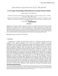
<strong>Study</strong> <strong>of</strong> <strong>BNKLBT</strong>-<strong>1.5</strong> <strong>lead</strong>-<strong>free</strong> <strong>ceramic</strong>/<strong>epoxy</strong> 1-3 <strong>composites</strong><br />
S. H. Choy, a� W. K. Li, H. K. Li, K. H. Lam, and H. L. W. Chan<br />
Department <strong>of</strong> Applied Physics and Materials Research Centre, The Hong Kong Polytechnic University,<br />
Hunghom, Kowloon, Hong Kong, China<br />
�Received 30 August 2007; accepted 15 October 2007; published online 12 December 2007�<br />
Bismuth sodium titanate based <strong>lead</strong>-<strong>free</strong> <strong>ceramic</strong> fiber with the chemical formula <strong>of</strong><br />
0.885�Bi0.5Na0.5�TiO3–0.05�Bi0.5K0.5�TiO3–0.015�Bi0.5Li0.5�TiO3–0.05BaTiO3, <strong>BNKLBT</strong>-<strong>1.5</strong>, has<br />
been fabricated by a powder-based extrusion method. The <strong>ceramic</strong> fibers with 400 �m diameter<br />
were well crystallized after being calcined at 800 °C and sintered at 1170 °C. The piezoelectric and<br />
ferroelectric properties <strong>of</strong> the single fiber were found to be 155 pC/N and �34.5 �C/cm2 ,<br />
respectively, which is comparable with that in bulk sample. 1-3 <strong>ceramic</strong>/polymer <strong>composites</strong> were<br />
fabricated by two routes, including dice and filled method and fiber pick-and-place method.<br />
Theoretical models were used to calculate the piezoelectric properties <strong>of</strong> the <strong>composites</strong> and<br />
compared with experimental results. © 2007 American Institute <strong>of</strong> Physics.<br />
�DOI: 10.1063/1.2821752�<br />
INTRODUCTION<br />
Lead zirconate titanate �Pb�Zr,Ti�O 3, abbreviated as<br />
PZT� <strong>ceramic</strong>s are commonly used piezoelectric materials<br />
due to their superior piezoelectric properties. However, the<br />
high PbO vaporization and contamination during processing<br />
and disposal cause a crucial environmental pollution. For this<br />
reason, it is desirable to use <strong>lead</strong>-<strong>free</strong> piezoelectric <strong>ceramic</strong>s<br />
to replace PZT in the near future. The search for alternative<br />
piezoelectric materials is now a very active research topic<br />
and a great deal <strong>of</strong> attention has been focused on<br />
Bi 0.5Na 0.5TiO 3 �BNT�-based materials.<br />
It is known that bismuth sodium titanate<br />
�Bi 1/2Na 1/2�TiO 3 composition �BNT� is one type <strong>of</strong> important<br />
<strong>lead</strong>-<strong>free</strong> <strong>ceramic</strong>s with perovskite structure discovered by<br />
Smolenskii et al. in 1960s. 1 At room temperature, BNT has a<br />
relatively large remnant polarization P r=38 �C/cm 2 and a<br />
high coercive field E c=7.3 MV/m. It also has a high Curie<br />
temperature �T C=320 °C�. 2,3 However, this material has a<br />
high leakage current during poling which caused incomplete<br />
poling. In order to improve the performance <strong>of</strong> BNT-based<br />
<strong>lead</strong>-<strong>free</strong> piezoelectric <strong>ceramic</strong>s, different dopings in BNTbased<br />
system have been used, including BaTiO 3,<br />
Bi 0.5K 0.5TiO 3, NaNbO 3,Ba�Cu 0.5W 0.5�O 3, etc. 4–8 The modified<br />
BNT <strong>ceramic</strong>s showed improvement in either easier to<br />
pole or have enhanced piezoelectric properties compared to<br />
pure BNT <strong>ceramic</strong>s. Based on the finding <strong>of</strong> those binary<br />
systems, multicomponent systems were developed and it was<br />
found that the properties <strong>of</strong> BNT can be further enhanced.<br />
�Bi 0.5Na 0.5�TiO 3–�Bi 0.5K 0.5�TiO 3–BaTiO 3 �BNKBT� is a<br />
system which is firstly reported by Nagata et al. 8 In our<br />
previous work, 0.90�Bi 0.5Na 0.5�TiO 3–0.05�Bi 0.5K 0.5�TiO 3–<br />
0.05BaTiO 3 �BNKBT-5� was found to have good performance<br />
in overall properties. 9,10 In another similar system, the<br />
�1−x��Bi 0.5Na 0.5�TiO 3–x�Bi 0.5K 0.5�TiO 3 system, the piezoelectric<br />
d 33 constant, and electromechanical planar coupling<br />
factor k p were enhanced by doping small amount <strong>of</strong> lithium<br />
a� Electronic mail: apshchoy@polyu.edu.hk.<br />
JOURNAL OF APPLIED PHYSICS 102, 114111 �2007�<br />
ions to form �Bi 0.5Li 0.5�TiO 3 �BLT� in the system. 11–13<br />
The properties <strong>of</strong> �0.90−x��Bi 0.5Na 0.5�TiO 3–<br />
0.05�Bi 0.5K 0.5�TiO 3–x�Bi 0.5Li 0.5�TiO 3–0.05BaTiO 3 <strong>ceramic</strong>s<br />
�abbreviated as <strong>BNKLBT</strong>-100x, with x ranged from<br />
0 to 2.5 mol %� system have been investigated. Variations <strong>of</strong><br />
the electrical properties and structures with the amount <strong>of</strong><br />
BLT have been examined. It was found the <strong>BNKLBT</strong>-<strong>1.5</strong> has<br />
good piezoelectric and dielectric properties which is a potential<br />
candidate for different device applications. 14,15<br />
In this study, <strong>BNKLBT</strong> <strong>ceramic</strong>s were fabricated in fiber<br />
form using a powder-based extrusion method and in disk<br />
form using a conventional metal oxide mixing method.<br />
<strong>BNKLBT</strong>/<strong>epoxy</strong> 1-3 <strong>composites</strong> with different volume fractions<br />
were then fabricated by a dice-and-fill �DF� method<br />
�using <strong>BNKLBT</strong> disks� and a fiber-pick-and-place �FP�<br />
method �using <strong>BNKLBT</strong> fibers�. Theoretical model was used<br />
to calculate piezoelectric properties <strong>of</strong> the <strong>composites</strong> and<br />
compared with the experimental results.<br />
EXPERIMENTAL PROCEDURE<br />
A conventional mixed oxide technique was used to prepare<br />
the <strong>BNKLBT</strong>-<strong>1.5</strong> <strong>ceramic</strong> powder. Reagent grade<br />
Bi 2O 3,Na 2CO 3, BaCO 3,K 2CO 3,Li 2CO 3, and TiO 2 were<br />
used as the raw materials. They were weighed according to<br />
the formula 0.885�Bi 0.5Na 0.5�TiO 3–0.05�Bi 0.5K 0.5�TiO 3–<br />
0.015�Bi 0.5Li 0.5�TiO 3–0.05BaTiO 3. The powder was ball<br />
milled for 10 h in ethanol using zirconia balls. Calcination<br />
was conducted at 800 °C for 2 h. The powder was then ball<br />
milled together with ethanol for 10 h to obtain powder with<br />
particle size around 1–3 �m. For <strong>ceramic</strong> disks, polyvinyl<br />
alcohol solution �PVA 5 wt %� was added into the powder as<br />
binders after drying the powder. They were well mixed and<br />
pressed in disk shape. The disk samples were then sintered at<br />
1170 °C for 2 h in air. The final dimensions <strong>of</strong> the disks are<br />
10 mm in diameter and 1.3 mm thick.<br />
<strong>BNKLBT</strong> green fibers were extruded using slurry<br />
formed by mixing presintered <strong>BNKLBT</strong> powder with suitable<br />
amounts <strong>of</strong> binder. Poly�acrylic acid� �25% aqueous so-<br />
0021-8979/2007/102�11�/114111/5/$23.00 102, 114111-1<br />
© 2007 American Institute <strong>of</strong> Physics<br />
Downloaded 09 Oct 2008 to 158.132.12.80. Redistribution subject to AIP license or copyright; see http://jap.aip.org/jap/copyright.jsp
114111-2 Choy et al. J. Appl. Phys. 102, 114111 �2007�<br />
lution� was dissolved in water to form a binder solution. The<br />
powder to binder solution ratio was 1: 0.2. Then the mixture<br />
was stirred using a magnetic stirrer until it became a uniform<br />
slurry. The slurry was poured into a metal spinnerette and<br />
placed into a fiber extrusion machine equipped with a heater.<br />
After the slurry has been densified in the spinnerette at<br />
65 °C for 15 min, the fiber was extruded using a gel-spun<br />
fiber machine �OneShot III from Alex James & Assoc., Inc�.<br />
The spinnerette was equipped with a die <strong>of</strong> 500 �m pinhole.<br />
The fibers were collected on a spindle. Diameter <strong>of</strong> the green<br />
fibers was �450 �m.<br />
Since the green fibers contain high organic contents, removal<br />
<strong>of</strong> the organics usually results in a large shrinkage and<br />
cracking <strong>of</strong> the fibers. In order to prevent fiber cracking, the<br />
heating procedure and atmosphere should be adjusted.<br />
Guided by the thermogravimetric analysis �TGA� pr<strong>of</strong>ile <strong>of</strong><br />
the green fibers, a slow heating rate <strong>of</strong> 0.5 °C/min in reducing<br />
atmosphere �CO� during pyrolysis was used to avoid<br />
fiber cracking. The pyrolyzed fibers were subsequently sintered<br />
at 1170 °C for 2 h to obtain dense and crack-<strong>free</strong><br />
<strong>BNKLBT</strong> <strong>ceramic</strong> fibers. The diameter <strong>of</strong> the sintered fiber<br />
was about 400 �m.<br />
The microstructure <strong>of</strong> the <strong>ceramic</strong> fibers was studied by<br />
a scanning electron microscope �Leica Stereoscan 440�. The<br />
P-E hysteresis loops <strong>of</strong> the disks and fibers were evaluated<br />
by a standard Sawyer-Tower circuit at 100 Hz. The density<br />
<strong>of</strong> the sintered samples was measured using the Archimedes<br />
principle.<br />
A Disco DAD 321 automatic dicing saw, equipped with<br />
a flange type diamond saw blade <strong>of</strong> 70 �m thickness and<br />
55 mm outer diameter �Disco NBC-Z 2050 55�0.07�40�,<br />
was used to carry out the dicing operation for fabricating the<br />
1-3 <strong>BNKLBT</strong>-<strong>1.5</strong>/<strong>epoxy</strong> 1-3 DF <strong>composites</strong>. Two perpendicular<br />
sets <strong>of</strong> equal spaced grooves were cut into the<br />
<strong>BNKLBT</strong>-<strong>1.5</strong> disks. Due to blade vibration, the resulting<br />
grooves in the disk were about 77–81 �m wide<br />
��10% –15% wider than the blade thickness�. Therefore, by<br />
making different number <strong>of</strong> cuts per direction �cpd�, composite<br />
disks with different <strong>BNKLBT</strong>-<strong>1.5</strong> element widths �L� and<br />
different volume fractions � <strong>of</strong> <strong>BNKLBT</strong>-<strong>1.5</strong> from 0.60–<br />
0.89 were obtained. Then filling <strong>of</strong> <strong>epoxy</strong> �Ciba Araldite <strong>epoxy</strong><br />
�Resin LY5210+Hardener HY2954 in a weight ratio <strong>of</strong><br />
1:0.53�� under vacuum was carried out. The samples were<br />
placed in an oven under 40 °C for 14 h for complete curing.<br />
For the 1-3 fiber/<strong>epoxy</strong> FP <strong>composites</strong>, sintered<br />
<strong>BNKLBT</strong>-<strong>1.5</strong> <strong>ceramic</strong> fibers were aligned in a plastic tube<br />
with diameter <strong>of</strong> 6 mm and filled with <strong>epoxy</strong>. Ciba Araldite<br />
<strong>epoxy</strong> was used as the matrix material. The <strong>epoxy</strong> was carried<br />
under the same condition described above and a <strong>ceramic</strong><br />
fiber/<strong>epoxy</strong> 1-3 composite rod was formed. Then the rod was<br />
sliced into composite disks and polished to a proper thickness.<br />
All the composite disks were painted with an air-dried<br />
silver paint �G3691 Agar Scientific� as electrodes on both top<br />
and bottom surfaces <strong>of</strong> the disk. The composite was polarized<br />
at 25 °C under an electric field <strong>of</strong> 4.0 MV/m for<br />
10 min in a silicone oil bath.<br />
The d 33 piezoelectric coefficient <strong>of</strong> the dc poled <strong>ceramic</strong><br />
fibers were measured by a ZJ-3D d 33 meter from Beijing<br />
FIG. 1. �Color online� �a� SEM micrograph and �b� photograph <strong>of</strong> sintered<br />
<strong>BNKLBT</strong>-<strong>1.5</strong> fibers.<br />
Institute <strong>of</strong> Acoustics. The impedance and phase versus frequency<br />
spectra <strong>of</strong> the samples were measured using an<br />
impedance/gain phase analyzer �Hewlett Packard 4294�. The<br />
analyzer was also used to measure the capacitance and dielectric<br />
loss <strong>of</strong> the samples.<br />
RESULTS AND DISCUSION<br />
The scanning electron microscopy �SEM� micrograph <strong>of</strong><br />
the cross section <strong>of</strong> a sintered <strong>BNKLBT</strong>-<strong>1.5</strong> fiber is shown in<br />
Fig. 1�a� and Fig. 1�b� shows the photograph <strong>of</strong> a sintered<br />
<strong>BNKLBT</strong>-<strong>1.5</strong> fibers. The sintered fibers are straight, dense,<br />
and crack-<strong>free</strong>. It indicates that the fibers fabricated by powder<br />
extrusion method have good quality when both the pyrolysis<br />
and sintering processes are well controlled.<br />
The polarization-electric field �P-E� loop measurement<br />
<strong>of</strong> <strong>BNKLBT</strong> fiber was performed using a Sawyer-Tower<br />
FIG. 2. P-E loops <strong>of</strong> <strong>BNKLBT</strong> fiber and disk.<br />
Downloaded 09 Oct 2008 to 158.132.12.80. Redistribution subject to AIP license or copyright; see http://jap.aip.org/jap/copyright.jsp
114111-3 Choy et al. J. Appl. Phys. 102, 114111 �2007�<br />
FIG. 3. �Color online� Photographs <strong>of</strong> 1-3 fiber/<strong>epoxy</strong> FP <strong>composites</strong> with<br />
different <strong>ceramic</strong>s volume fractions �a� �=0.26, �b� �=0.3, �c� �=0.4, �d�<br />
�=0.54, and �e� �=0.65, respectively.<br />
bridge circuit. The P-E loops <strong>of</strong> the fiber are shown in Fig. 2.<br />
The remnant polarization �P r� <strong>of</strong> the fiber is about<br />
3<strong>1.5</strong> �C/cm 2 , which is comparable with the bulk <strong>ceramic</strong><br />
sample �P r�32.4 �C/cm 2 �. The coercive field �E c� <strong>of</strong> the<br />
fiber �E c�2.6 kV/mm� is lower than that <strong>of</strong> the <strong>ceramic</strong>s<br />
disk �E c=3.4 kV/mm�.<br />
The properties <strong>of</strong> the 1-3 <strong>composites</strong> with different <strong>ceramic</strong><br />
volume fractions ��� and fabricated by different techniques<br />
are listed in Table I and the properties <strong>of</strong> pure <strong>ceramic</strong>s<br />
disk, <strong>ceramic</strong>s fiber, and pure <strong>epoxy</strong> are also listed. The<br />
properties <strong>of</strong> the <strong>ceramic</strong> fibers are comparable with <strong>ceramic</strong><br />
disks showing that the fibers have good quality. Figures 3<br />
and 4 show the photographs <strong>of</strong> the 1-3 FP <strong>composites</strong> and<br />
1-3 DF <strong>composites</strong> with different <strong>ceramic</strong>s volume fractions,<br />
respectively.<br />
Performances <strong>of</strong> 1-3 piezo<strong>composites</strong> can be predicted<br />
by the modified series and parallel models 16,17 as follows:<br />
�¯ = �� + �1−���˜ , �1�<br />
d¯<br />
33 = �d33s˜ 11<br />
, �2�<br />
S���<br />
T<br />
�¯ 33 = ��33<br />
T<br />
+ �1−���˜11 − ��1−��d33 , �3�<br />
S���<br />
E<br />
S��� = �s˜ 11 + �1−��s33, �4�<br />
d¯<br />
33<br />
k¯<br />
33 =<br />
��¯ 33<br />
T E<br />
s¯33<br />
, �5�<br />
g¯ 33 = d¯ 33<br />
. �6�<br />
T<br />
�¯ 33<br />
In these equations, the materials parameters <strong>of</strong> <strong>epoxy</strong> were<br />
denoted by a curved bar on top <strong>of</strong> the parameters. The effective<br />
materials parameters <strong>of</strong> the composite were denoted<br />
with a bar.<br />
This model is based on the equal-strain assumption<br />
which can well predict the properties <strong>of</strong> 1-3 piezo<strong>composites</strong><br />
with high <strong>ceramic</strong> volume fractions. Some important properties<br />
are predicted and the results are presented in Fig. 5. The<br />
solid line represents the calculated results and the solid<br />
squares �for <strong>epoxy</strong> and <strong>BNKLBT</strong>-<strong>1.5</strong>�, circles �for FP com-<br />
TABLE I. The properties <strong>of</strong> <strong>BNKLBT</strong> fibers, bulk samples, pure <strong>epoxy</strong>, and 1–3 <strong>ceramic</strong>/<strong>epoxy</strong> 1–3 <strong>composites</strong> with different <strong>ceramic</strong>s volume fractions.<br />
Parameters Epoxy<br />
�=0.26<br />
�FP�<br />
�=0.3<br />
�FP�<br />
�=0.4<br />
�FP�<br />
�=0.54<br />
�FP�<br />
�=0.65<br />
�FP�<br />
FIG. 4. �Color online� Photographs <strong>of</strong> 1-3 <strong>ceramic</strong>/<strong>epoxy</strong> DF <strong>composites</strong><br />
with different <strong>ceramic</strong>s volume fractions �a� �=0.60, �b� �=0.70, �c� �<br />
=0.83, and �d� �=0.89, respectively.<br />
�=0.60<br />
�DF�<br />
�=0.70<br />
�DF�<br />
�=0.83<br />
�DF�<br />
2<br />
�=0.89<br />
�DF� Ceramic disc Ceramic fiber<br />
Density<br />
�kg/m 3� 1133 2570.5 2525.3 2953.6 3633.4 3780.5 3890 4350 4943 5229 5800 5770<br />
�33 at 1 kHz 5.15 162.7 253.5 253.5 322 424.5 450.5 505.97 610.853 689.835 684.3 786.8<br />
d33 �pC/N� 0 142 147 156 151 161 156 160 164 170 154.7 155.5<br />
g33 ��10−3 Vm/N�<br />
0 9.86 6.55 6.95 5.33 4.29 3.91 3.57 3.03 2.78 2.55 2.23<br />
tan � �%� at<br />
1 kHz<br />
1.4 3.9 4 4.2 4.9 3.9 3.2 3.1 3.5 3.6 1.67 3.52<br />
k factor 0 0.56 0.557 0.5 0.5 0.53 0.50 0.53 0.52 0.364 kt=0.519 k33= kp=0.309 0.549<br />
Acoustic<br />
impedance Z<br />
�MRayl�<br />
2.99 8.62 8.72 11.31 13.72 15.89 13.71 17.81 20.67 25.13 26.41 26.41<br />
Downloaded 09 Oct 2008 to 158.132.12.80. Redistribution subject to AIP license or copyright; see http://jap.aip.org/jap/copyright.jsp
114111-4 Choy et al. J. Appl. Phys. 102, 114111 �2007�<br />
FIG. 5. The calculated and experimental results <strong>of</strong> 1-3 piezo<strong>composites</strong> include density, relative permittivity � r, piezoelectric strain constant d 33, piezoelectric<br />
voltage constant g 33, and electromechanical coupling coefficient k t �circle, FP <strong>composites</strong>; triangle, DF <strong>composites</strong>�.<br />
posites�, and triangles �for DF <strong>composites</strong>� represent the experimental<br />
results. It shows that the results agree quite well<br />
with the theoretical model. The electromechanical coupling<br />
factor �k t� <strong>of</strong> the 1-3 DF <strong>composites</strong> with volume fraction <strong>of</strong><br />
�=0.89 cannot be determined accurately due to the mode<br />
coupling effect in the <strong>composites</strong>. For the �=0.89 composite,<br />
the pillar-shaped <strong>ceramic</strong> element inside the 1-3 compos-<br />
ites with the length and width �L� <strong>of</strong> �1.6 mm and thickness<br />
�t� <strong>of</strong> �1 mm. Based on the mode coupling model, 16,17 L/t<br />
ratio is an important factor and coupling between the thickness<br />
and transverse resonance modes occurs when the L/t<br />
ratio is close to <strong>1.5</strong>. For BNBT-6, the mode coupling occurs<br />
when L/t=1.45. 18,19 Figure 6 shows the frequency<br />
impedance/phase spectra <strong>of</strong> the 1-3 DF <strong>composites</strong> with ce-<br />
Downloaded 09 Oct 2008 to 158.132.12.80. Redistribution subject to AIP license or copyright; see http://jap.aip.org/jap/copyright.jsp
114111-5 Choy et al. J. Appl. Phys. 102, 114111 �2007�<br />
FIG. 6. �Color online� The frequency-impedance/phase spectrum <strong>of</strong> a 1-3 <strong>ceramic</strong>/<strong>epoxy</strong> <strong>composites</strong> disks with �a� �=0.70 and �b� �=0.89, respectively.<br />
ramics volume fractions <strong>of</strong> 0.70 and 0.89, respectively. It is<br />
seen from Fig. 6�b� that the resonance peak split into two<br />
peaks in the �=0.89 composite.<br />
The major advantage <strong>of</strong> 1-3 <strong>ceramic</strong>/<strong>epoxy</strong> <strong>composites</strong><br />
is the flexibility in adjusting the properties <strong>of</strong> the <strong>composites</strong><br />
by varying the <strong>ceramic</strong> volume fraction to fit specific device<br />
applications. Ultrasonic transducer for nondestructive evaluation<br />
�NDE� is one <strong>of</strong> the potential applications for the <strong>composites</strong>.<br />
Most <strong>of</strong> the NDE transducer uses aluminum as housing<br />
and front matching layer. The acoustic impedance<br />
matching between the front layer and the sensing element is<br />
important for efficient energy transfer. The acoustics impedance<br />
<strong>of</strong> aluminum is 17 MRayl, which is close to the composite<br />
with <strong>ceramic</strong> volume fractions <strong>of</strong> 0.65<br />
��15.89 MRayl� and 0.70 ��17.81 MRayl�. The good<br />
acoustics impedance matching can improve the performance<br />
<strong>of</strong> the transducer.<br />
CONCLUSION<br />
<strong>BNKLBT</strong>-<strong>1.5</strong> <strong>ceramic</strong> fibers have been prepared successfully<br />
using a powder-based extrusion method. The <strong>ceramic</strong><br />
fibers were dense and crack-<strong>free</strong>. Measurements<br />
showed that the fibers have properties comparable with the<br />
bulk <strong>ceramic</strong> samples. Both <strong>ceramic</strong> fibers and bulk <strong>ceramic</strong><br />
disks are used to fabricate 1-3 <strong>ceramic</strong>/<strong>epoxy</strong> <strong>composites</strong><br />
with different <strong>ceramic</strong> volume fractions by using fiber pickand-place<br />
�FP� and dice-and-fill �DF� techniques. The piezoelectric<br />
properties <strong>of</strong> the <strong>composites</strong> were measured and<br />
compared with the theoretical model and it was found that<br />
the experimental results agree quite well with the model. The<br />
<strong>lead</strong>-<strong>free</strong> <strong>ceramic</strong>s fibers/<strong>epoxy</strong> 1-3 <strong>composites</strong> can enhance<br />
the electromechanical coupling coefficient and provide a<br />
good acoustics impedance matching with aluminum which is<br />
useful for ultrasonic transducer applications.<br />
ACKNOWLEDGMENTS<br />
This work was supported by the Hong Kong Research<br />
Grants Council �PolyU 5137/04E�, PolyU internal grants �1-<br />
BBZ3 and 1-BB95�, and Center for Smart Materials <strong>of</strong> The<br />
Hong Kong Polytechnic University.<br />
1<br />
G. A. Smolenskii, V. A. Isupov, A. I. Agranovskaya, and N. N. Krainik,<br />
Sov. Phys. Solid State 2, 2651 �1961�.<br />
2<br />
J. Suchanicz, K. Roleder, A. Kania, and J. Handerek, Ferroelectrics 77,<br />
107 �1988�.<br />
3<br />
M. S. Hagiyev, I. H. Ismaizade, and A. K. Abiyev, Ferroelectrics 56, 215<br />
�1984�.<br />
4<br />
T. Takanaka, K. I. Maruyama, and K. Sakata, Jpn. J. Appl. Phys., Part 1<br />
30, 2236 �1991�.<br />
5<br />
A. Sasaki, T. Chiba, Y. Mamiya, and E. Otsuki, Jpn. J. Appl. Phys., Part 1<br />
38, 5564 �1999�.<br />
6<br />
T. Takenaka, T. Okuda, and K. Takegahara, Ferroelectrics 196, 495�1997�.<br />
7<br />
X. X. Wang, H. L. W. Chan, and C. L. Choy, J. Am. Ceram. Soc. 86, 1809<br />
�2003�.<br />
8<br />
H. Nagata, M. Yoshida, Y. Makiuchi, and T. Takenaka, Jpn. J. Appl. Phys.,<br />
Part 1 42, 7401�2003�.<br />
9<br />
X. X. Wang, X. G. Tang, and H. L. W. Chan, Appl. Phys. Lett. 85, 91<br />
�2004�.<br />
10<br />
X. X. Wang, S. H. Choy, X. G. Tang, and H. L. W. Chan, J. Appl. Phys.<br />
97, 104101 �2005�.<br />
11<br />
D. M. Lin, D. Q. Xiao, J. G. Zhu, and P. Yu, Phys. Status Solidi A 202,<br />
R89 �2005�.<br />
12<br />
D. M. Lin, D. Q. Xiao, J. G. Zhu, P. Yu, H. J. Yan, and L. Z. Li, Mater.<br />
Lett. 58, 615 �2004�.<br />
13 D. M. Lin, D. Q. Xiao, J. G. Zhu, P. Yu, H. J. Yan, L. Z. Li, and W. Zhang,<br />
Cryst. Res. Technol. 39, 30�2004�.<br />
14 S. H. Choy, X. X. Wang, H. L. W. Chan, and C. L. Choy, Appl. Phys. A:<br />
Mater. Sci. Process. 89, 775 �2007�.<br />
15 G. Edwards, S. H. Choy, H. L. W. Chan, D. A. Scott, and A. Batten, in<br />
Appl. Phys. A: Mater. Sci. Process. 88, 209 �2007�.<br />
16 H. L. W. Chan and J. Unsworth, IEEE Trans. Ultrason. Ferroelectr. Freq.<br />
Control 36, 434 �1989�.<br />
17 W. A. Smith and B. A. Auld, IEEE Trans. Ultrason. Ferroelectr. Freq.<br />
Control 38, 40�1991�.<br />
18 D. Y. Wang, thesis, The Hong Kong Polytechnic University, 2002.<br />
19 D. Y. Wang and H. L. W. Chan, Mater. Sci. Eng., B 99, 147 �2003�.<br />
Downloaded 09 Oct 2008 to 158.132.12.80. Redistribution subject to AIP license or copyright; see http://jap.aip.org/jap/copyright.jsp