LAE LCD 15 Manual - Server Racks Australia
LAE LCD 15 Manual - Server Racks Australia
LAE LCD 15 Manual - Server Racks Australia
- No tags were found...

You also want an ePaper? Increase the reach of your titles
YUMPU automatically turns print PDFs into web optimized ePapers that Google loves.
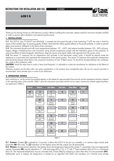
INSTRUCTIONS FOR INSTALLATION AND USE.4. THERMOSTAT CONTROL4.1 Thermostat control is based on comparing the temperature T1, the set point *SP and the hysteresis *HYS.Example: SP= 2.0; HYS= 1.5, compressor Off with T1= +2.0° and On with T1= +3.5° (2+1.5).The compressor only switches On again if the Off time period determined by CRT since the previous switchover has elapsed. Whenevera very small hysteresis HYS must be maintained, it is advised that a suitable value for CRT is selected in order to reduce the number ofstarts per hour.4.2 If sensor T1 fails, the output is controlled by parameter CDC as a proportion of a 10 minute operating cycle.Example: CDC=06, 6 minutes On, 4 minutes Off.4.3 If door switch input control has been enabled (DS=YES), parameter CSD determines the delay between when the door is openedand the compressor stopping.* Actual setpoint and hysteresis depend on the selection I/II: in mode I, the reference parameters are SP and HYS while in mode II,IISP and IIHY.5. DEFROSTING5.1 Defrosting starts automatically when necessary time has elapsed to obtain the defrosting frequency set with *DFR. For example,with DFR=4 there will be 4 defrostings per 24 hours, so defrosting occurs once every 6 hours.The internal timer is set to zero when power is applied to the controller and at each subsequent defrost start. When the controller is puton a standby, the accumulated time count is “frozen” (is not incremented).Defrosting may also be induced manually by keeping the button pressed for 2 seconds.During a High Pressure alarm (see par. 7.3), defrost is suspended.5.2 Once defrost has started, the outputs are controlled according to parameter DTY as per the following table:DTY DEFROST COMPRESSOROFF Off OffELE On OffGAS On OnTABLE 35.3 Defrost lasts for the time DTO but, if the evaporator probe has been enabled (T2=YES) and temperature DLI is achieved beforethis time elapses, defrost will be terminated in advance.If parameter DRN is greater than 0, before cooling starts all outputs will remain off for the time assigned to DRN. This phase, calleddrain down, will allow a complete ice melting and the drain of the resulting water.* The actual defrost frequency depends on the selection I/II: in mode I, the reference parameter is DFR while in mode II it’s IIDF.6. EVAPORATOR FANS6.1 During thermostatic control, the evaporator fans are controlled by parameter *FTC and FPC. With FTC=NO, the fans operatecontinuously regardless of the FPC value set. Alternatively, when FTC=YES the evaporator fans will operate in conjunction with thecompressor (i.e. when the compressor runs the fans will run), but dependant upon the FPC value set they will On/Off cycle after thecompressor has stopped. With FPC set between 1 to 3, you will obtain On/Off ratios of respectively, 33%, 50% and 60% with fixed60 second off times. Therefore, once the compressor has stopped, with FPC=1 (33%) the fans will run for 30 seconds and stay off for60 seconds. If FPC=2 (50%) the fans will run for 60 seconds and remain off for 60 seconds; with FPC=3 (60%) the fans will run for 90seconds and stay switched off for 60 seconds. This cycle pattern will continue until the compressor starts again. With FPC=0, the fanswill follow the compressor cycle only.This fan control function aims at recovering the maximum cooling effect available at the evaporator as well as greatly reducing unwantedheat generated by the evaporator fan motors, so increasing the energy efficiency. Cycling the fans also avoids air stratification, andallowing the temperature measured by probe “T1” to be updated, and thus accurate. If the temperature to be maintained is abovefreezing then the maximum humidity is maintained in the chilled environment.6.2 If the <strong>LCD</strong><strong>15</strong> is connected to a door switch and door switch control is enabled (DS=YES), during thermostatic control if the door isopened, the fans will be stopped immediately.6.3 During defrost, the fans are controlled by parameter FID; with FID=YES the fans remain on all through defrosting. With FID=NO,the fans will be stopped and will only re-start when the conditions in paragraph 6.4 have been met.6.4 After defrosting, if probe T2 is active (T2=YES), temperature FDD provides evaporator fan re-start. So the evaporator fans will notrun until the evaporator has a temperature lower than FDD. If such condition doesn’t occur within 4 minutes following defrost termination,the fans will however be switched on again.
INSTRUCTIONS FOR INSTALLATION AND USE.* The way the fans will be controlled depends on the selection I/II: in mode I they work according to FTC, while in mode II the fanswork according to IIFT.7. ALARMSWith <strong>LCD</strong><strong>15</strong>, correct operation of the refrigerator and thermostat may be monitored by a wide range of functional and diagnosticsalarms, individually selectable by means of the relevant parameters. The alarm warnings are given on the display through explicitindications (see following par.) and intermittent buzzer sounding. During an alarm, by pressing any button, the buzzer is muted.Then, if the alarm persists, the buzzer will be periodically switched on for 20 seconds every 60 minutes, until the alarm ends (thedisplay indications remain on all the time). The repeated acoustic warning applies to all alarms with the exception of the condensercleaning alarm. Operation of the various elements is given in detail below.7.1 The parameters ATL and ATH define two differential temperatures that, referred to the set point, determine the temperaturealarm thresholds. ATL establishes the alarm differential for temperatures below set point, ATH the alarm differential for temperaturesabove set point + hysteresis. Putting one or both differentials to 0 cuts out the corresponding alarm.Example: SP= -20, HYS= 2.0, ATL= -5.0, ATH= 05.0; the alarm thresholds are set at –25°(-20-5) and –13° (-20+2+5).The alarm warning may be immediate or delayed by the time ATD whenever this is greater than 0. The indication HI for hightemperature and LO for low temperature alarm blinks on the display. The alarm indication remains stored in the display, evenwhen the alarm is over, until you acknowledge the alarm manually by pressing any button.The high temperature alarm is bypassed during defrosting.7.2 If a suitable door switch has been connected to detect the door status and door switch input control has been enabled(DS=YES), the door open alarm function is enabled. In this way, if the door remains open the controller will react after the timedelay set with ADO by displaying the alarm source through the indication DO .7.3 To monitor the condenser temperature to avoid gas pressure from getting too high, it’s necessary to secure probe T3 to thecondenser firmly (see 1.3) and enable condenser probe control (T3=YES). Parameter AHT determines the condenser temperaturealarm threshold and parameter AHM determines the reaction following the temperature rising over AHT. With AHM=ALR the onlyreaction will be the buzzer sounding and HP being displayed. Alternatively, with AHM=STP, besides the alarm indication thecompressor will be stopped immediately and defrosts suspended.With AHM=NON, all functions related to the High Pressure alarm are inhibited.7.4 Assigning a value greater than 0 to the parameter ACC enables the indication for periodic cleaning of the condenser.Subsequently, when the count of compressor hours of operation reaches the equivalent in weeks set with ACC, an indication forcleaning appears on the display.Example: with ACC=16 there is a warning once every 16x7(weeks)x24(hours)=2688 hours of compressor operation, so, assuming for thisan operation with 5 minutes On and 5 minutes Off - after approx. 32 weeks.In order to clear the time counter, follow the prescribed procedure in paragraph 2.3.7.5 Upon failure of probe T1 or, if enabled, probes T2 and T3, probe failure is signalled with the blinking indication E1 or E2 orE3 respectively.8. TEMPERATURE STORAGEThe <strong>LCD</strong><strong>15</strong> features a system for permanent storage of the minimum and maximum temperature logged during operation. This system isa valid help to achieve compliance with the HACCP directive in its part relating to a correct preservation of foodstuffs. Temperature ismeasured by probe T1 which should therefore be placed in a point where the temperature of the preserved product may always bemeasured correctly. The logging is however subject to some simple rules that filter the data and give a rational interpretation. The loggingis suspended during the periods in which the refrigerator is put on a standby and during defrostings and, during the normal operation(thermostatic control), it’s “slowed down” through the parameter TLD. This parameter defines the time during which the measuredtemperature must permanently exceed the current value before the logging is performed. In this way, it will be possible to avoid idleloggings that don’t reflect the actual product temperature, for example, the door being left open, the temperature recovery after a defrostor other temporary short term temperature huntings.It is suggested that a reasonably long TLD time is programmed, for instance 5-<strong>15</strong> minutes, you then put the product into the refrigeratorand start a new logging cycle by clearing previous values (see par. 2.3). It will now suffice that at regular intervals, in the INFO menuyou check the minimum and maximum logged values in order to know if the product has been kept within the required temperature limits.9. AUXILIARY FUNCTIONS9.1 In addition to the basic functions described above, The <strong>LCD</strong><strong>15</strong> offers an innovative feature to enhance the performance of therefrigerator. Infact, you can select the control parameters between two different pre-programmed groups, in order for the fundamentalcontrol parameters to be adapted quickly to changing needs such as, for example: High/Low Temperature range change, stored productchange (meat, fish, vegetables …), maximum cooling capacity or energy saving. The parameters switched over in mode I and II are:SPL, SPH, SP, HYS, DFR, FTC and IISL, IISH, IISP, IIHY, IIDF, IIFT.
INSTRUCTIONS FOR INSTALLATION AND USE.With the parameter IISM you select if the changeover from Group I to Group II is made manually via the button II (IISM=MAN), orautomatically when heavy duty operation is detected (IISM=HDD) or inhibited (IISM=NON). The activation of Group II is signalled bythe lighting up of the relevant LED on the controller display.9.2 The automatic detection of “heavy duty operation” allows the control parameters to be modified in response to the specifictemporary needs of the refrigerator, such as: warm food being put into the cabinet, door being opened frequently etc. Control sensitivityto switch over from Group I to Group II is determined by parameter HDS (1=minimum, 5=maximum). An example of how to use suchfunction is reported in the following table:If we apply the above example to a refrigerator in a restaurant kitchen the controller will use the parameters of Group I during the closingtimes of the kitchen, when the need for cooling is minimum, therefore we can consider this as a “normal” operation condition. Group I“economy control” parameters will ensure both an optimum foodstuff preservation and considerable energy saving. Alternatively, duringvery busy periods (door being opened continuously to take out or load food), the controller will automatically select Group II to try andmaintain the average product temperature within correct values (lower setpoint), limit compressor wear by reducing the number of starts(higher hysteresis), avoid long defrost pauses which will worsen the preservation condition (lower defrost frequency or no defrosts at all),increase product cooling speed by keeping ventilation always active (FCT=NO). When the heavy duty period is over, the controller willautomatically resort back to Group I.NOTE: To make the automatic detection IISM=HDD work better, it is suggested that the value of hysteresis is not set too narrow (less than2°K) or the value of CRT is not set too high (longer than 2 minutes)9.3 The controller is provided with a serial port for connection to a PC or a programmer. In the first case it is important to assign to theparameter ADR a different value for each linked unit (peripheral address); with automatic programming, ADR should remain on 1.WARRANTYPARAMETER GROUP I GROUP IISetpoint SP= -18 IISP= -21Hysteresis HYS= 2.0 IIHY= 3.0Defrost frequency DFR= 3 IIDF= 1.. 0intermit. fans FTC= YES IIFT= NO<strong>LAE</strong> electronic SPA guarantees its products against defects due to faulty materials or workmanship for one (1) year from the date of manufacture shown on the container.The Company shall only replace products which are shown to be defective to the satisfaction of its own technical services. The Company shall not be under any liabilityand gives no warranty in the event of defects due to exceptional conditions of use, misuse or tampering.<strong>LAE</strong> electronic does not accept units back unless <strong>LAE</strong> electronic has previously given its allowance or request.
INSTRUCTIONS FOR INSTALLATION AND USE.WIRING DIAGRAM <strong>LCD</strong><strong>15</strong>CS3E-BPARTNER VENEZIA • 041 5460713VIA PADOVA, 2531046 ODERZO /TV /ITALYTEL. 0422 8<strong>15</strong>320 - 8<strong>15</strong>303TELEFAX 0422 814073www.lae-electronic.comE-mail: info@lae-electronic.com