CV 691 - Total Hydraulics BV
CV 691 - Total Hydraulics BV
CV 691 - Total Hydraulics BV
- No tags were found...

Create successful ePaper yourself
Turn your PDF publications into a flip-book with our unique Google optimized e-Paper software.
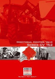
ContentsPage 3Page 4Page 5Page 6-7Page 8Page 9Page 9Page 10-11General InformationTechnical dataPerformance CurvesDimensionsRelief and Check ValvesSpool - Control characteristicsSpool ControlsOrder CodeDirectional Control Valve 2Series <strong>CV</strong> <strong>691</strong>
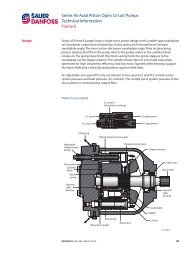
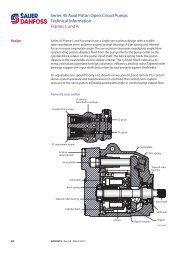
General InformationThe <strong>CV</strong><strong>691</strong> valve offers its user a very compact valve where the directional control valve is combined witha pressure compensated adjustable flow control valve in one body.It thereby reduces both cost and size by reducing required number of hoses and fittings and allows for amore compact installation.The <strong>CV</strong><strong>691</strong> has very good flow to pressure characteristic allowing a consistent flow to the motor independentof load pressure.The <strong>CV</strong><strong>691</strong> maintains a constant flow output independent of inlet flow changes, that are caused by speedchanges of the diesel engine.The <strong>CV</strong><strong>691</strong>’s built-in pressure relief valve gives a very distinct pressure cut off point allowing the motor tooperate from low pressure up to the pressure relief valve setting at a very constant flow.Easy installationThe valve has two pressure inlets and two tank outlets which allow the plumbing to be connected eitherfrom the side or top of the valve.It is also possible to connect several <strong>CV</strong><strong>691</strong> valves in series by using a HPCO adapter together withstandard fittings.The <strong>CV</strong><strong>691</strong> Relief ValvesThe relief valve (1) for the ports A & B is connected to the compensator spool and when the pressure settingis reached the oil dumps to the centre gallery.If a HPCO is installed for the use of down stream valves a second pressure relief valve (2) is required tocontrol the pressure out from the HPCO in the centre galleryThese two relief valves are working independent of each other.The <strong>CV</strong><strong>691</strong> is manufactured using the highest quality alloy cast iron which in combination with Nimco’sadvanced machining and control methods assure the precise accuracy of every component. Each valve istested and the results documented prior to shipment.Wide range of accessories.The <strong>CV</strong><strong>691</strong> offers a wide range spool and remote controls such as lever controls, cable controls. A hydraulickick-out is also available.3Directional Control ValveSeries <strong>CV</strong> <strong>691</strong>
Technical DataMax Pressure SettingMain Relief ValveTank lineFlow ratesMaximum for the valveTemperature RangeStandard seals NBR BUNA-N sealsInternal Leakage A(B) to T100 bar (1450 psi) and 46 mm²/s (cSt)(117 SSU) viscosity A and B portbar32010l/min110° C-40 to +80cm³/minMax 10psi4600145US GPM29°F-40 to +176inch³/min0.6FiltrationContamination level equal to or better thenViscosityRecommended operatingViscosity rangeStart viscosity up toWeight<strong>CV</strong> <strong>691</strong>18/14 according to ISO 4406mm²/s10-4001000Kg7.5NAS 1638-class 10cSt47 - 18754687lbs16.5Directional Control Valve 4Series <strong>CV</strong> <strong>691</strong>
Performance CurvesPressure relief characteristiclpm 10080604020030 60 90 120 150 180210BarLoad independent oil/flow, pressure compensatedSpool CharacteristicBar 10080604020030 60 90 120 150 180210Bar5Directional Control ValveSeries <strong>CV</strong> <strong>691</strong>
DimensionsEuropean view settingDirectional Control Valve 6Series <strong>CV</strong> <strong>691</strong>
DimensionsUS view setting7Directional Control ValveSeries <strong>CV</strong> <strong>691</strong>
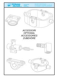
Relief ValveDifferential operated relief valve adjustable from 35 to320 bar (500-4600 psi).Control the pressure out from the HPCO.Part No: 4S-6020High Pressure Carry-Over Adaptators (Power Beyond)are available to serial connect the <strong>CV</strong> 601 with one ormore control valves.Part No: 11408-4S (BSP ¾″→ ¾″)(UNF 12 → 12)Part No: 11741-4S (BSP ¾″→ ¾″)(UNF 12 → 12)Tank Port Reduction Adaptator can be installed in theT1 port when the thread size is to be reduced.Part No: 4S-4384 (BSP ¾″ → ½″)(UNF 12 → 10)Directional Control Valve 8Series <strong>CV</strong> <strong>691</strong>
AdvantagesAdvantages of using integrated flow control valves vs seperate units<strong>CV</strong>791 Mounted with <strong>CV</strong><strong>691</strong>9Directional Control ValveSeries <strong>CV</strong> <strong>691</strong>
Spool - Control CharacteristicsAll of NIMCO’s spools are designed for specific flow rates in order to achieve optimal load controls characteristicsand to fully utilise the spools entire stroke. By optimising the balance between spools and valve housing,spring forces are minimized and exact maneuvering is achieved. Besides the standard spools listed designedfor maximum flow and minimum pressure drop there are also special spools available. For further informationconcerning these type of spools please contact your NIMCO representative.Spool typeSymbolOrder codeStandard spoolDouble acting1SSingle actingA-port2SASingle actingB-port2SBMotor4SSpool ControlsCodeType A-sideB-side TypeCode36.5(1.44)9Spring centered.Hand lever.EncasedS5101314Spring centered.Detent in pos.1, 2 and 3Spring centered.Detent in pos.2Spring centered.Detent in pos.354.5(2.15)71(2.8)98(3.86)Wire controlWDirectional Control Valve 10Series <strong>CV</strong> <strong>691</strong>
Order CodeExample 1<strong>CV</strong><strong>691</strong>-RV150-X-P2-1X-10S5-T2-GThis <strong>CV</strong><strong>691</strong> is equipped with a pressure relief valve at 150 bar on thecompensated flow, double acting spool (Code 1S) with detent in threepositions (code 10) and enclosed type hand lever control (S5).11Directional Control ValveSeries <strong>CV</strong> <strong>691</strong>
Order CodeCopy this page and use asyour technical order form.<strong>CV</strong> <strong>691</strong>Main relief valvePort A and BRV + pressure settingRelief ValveOnly used together withHPCO and down streamvalve operationRV + pressure settingif not applicable mark XPump inlet side P1top P2Spool type code page 9FlowAdjustmentP1BP2AT2Pressure Relief ValveOnly used togetherwith HPCOT1Pressure Relief Valve(Ports A and B)BSP GSAE SMetric MTank port side T1top T2High Pressure Carry-Over(Power Beyond) SThread ReducingAdaptor RSpool control B-side code page 9Spool control A-side code page 9Directional Control Valve 12Series <strong>CV</strong> <strong>691</strong>