

DIL-200 - Snap-on Equipment
DIL-200 - Snap-on Equipment
DIL-200 - Snap-on Equipment

You also want an ePaper? Increase the reach of your titles
YUMPU automatically turns print PDFs into web optimized ePapers that Google loves.
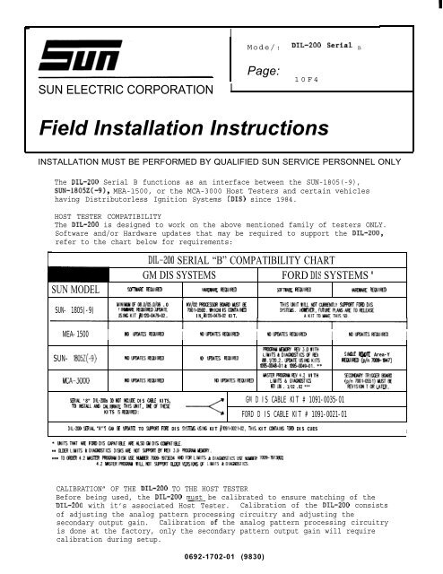
IMode/: <str<strong>on</strong>g>DIL</str<strong>on</strong>g>-<str<strong>on</strong>g>200</str<strong>on</strong>g> SerM BSUN ELECTRIC CORPORATIONIPage:10F4Field Installati<strong>on</strong> Instructi<strong>on</strong>sINSTALLATION MUST BE PERFORMED BY QUALIFIED SUN SERVICE PERSONNEL ONLYThe <str<strong>on</strong>g>DIL</str<strong>on</strong>g>-<str<strong>on</strong>g>200</str<strong>on</strong>g> Serial B functi<strong>on</strong>s as an interface between the SUN-1805(-9),SUN-1805Z(-9), MEA-1500, or the MCA-3000 Host Testers and certain vehicleshaving Distributorless Igniti<strong>on</strong> Systems (DIS) since 1984.HOST TESTER COMPATIBILITYThe <str<strong>on</strong>g>DIL</str<strong>on</strong>g>-<str<strong>on</strong>g>200</str<strong>on</strong>g> is designed to work <strong>on</strong> the above menti<strong>on</strong>ed family of testers ONLY.Software and/or Hardware updates that may be required to support the <str<strong>on</strong>g>DIL</str<strong>on</strong>g>-<str<strong>on</strong>g>200</str<strong>on</strong>g>,refer to the chart below for requirements:<str<strong>on</strong>g>DIL</str<strong>on</strong>g>-<str<strong>on</strong>g>200</str<strong>on</strong>g> SERIAL “B” COMPATIBILITY CHARTGM DIS SYSTEMS FORD DIS SYSTEMS ‘SUN MODEL WIWt Ewlfto Wm fifwlm Sm’wfw fKwlm liwlmf KwlmSUN- 1805(-9)1 1UlNllAJiFOL3.O/05.O/IM .0 kv/02FlmmwwE THlSU41TWlLLt43TCLM14TLY !3HU7TFIXDDISFIFw!itfEwlFm.mATE 7EL11-@592.WNICH lSCC?4TAltED SfJEIiS. t4MWR,FIJMEFlAt4SMifTOPILEASIUSltCKIT #3UIM47902. IN hlXk047!M2 KIT. AKITTOIAWTNISSII.MEA- 1500 I m WJEs REwlmI tolmmswwlml I Klwu!mwwlml I rtlwtlmsi+fwlm ISUN- 1805Z(-9) N)mml+fwlml to ml-n PIwlmMCA-3000FfRmuiE4nw Ffv3.owlTNLIUiTS&DIAUOSTICSCFRIV&3.1/2D.2.UMEUSltCKITSm5a4u-ol& ll%m49-ol. **SIU.E mm Area-YltC4MD(p/n7019-1947)lAmRPFWxftmGfv4.2 WITH Sm4MYmlmmvulNIUIMTESFfWIFfD tommsttwlml LI141TS & DIAU413TI13FC?f LM . 1/02 .02 ***(P&;yayl)M~:Wtlk ‘8” OIL-21W CO MIT MY-U DIS CM-E KITS, GM D IS CABLE KIT # 1091-0035-01TO lt6TAlLAMI CUlLRATE TNlSU41T, fMIXTtESEKITS IST+IWMD:FORD D IS CABLE KIT # 1091-0021-01OIL-2M ST?IAL “A’”S CM Ef LRMEEI TO SlJW4T FE4ill DIS S6TEM USItt KIT #W-CfJ2H12, TNIS KIT Cf14TAlNS FCFll DIS CUESI* U41TSTtUT ARE FfIQDIS CdfIATlf4-E JJEM9Q401S I3W'ATlEi.E.** CtXRLINITS &OlAU0STlC3 D1’Si6Afif NlT SlfRRTEN EV 3.0 FfU3VJilEMRf.*;* TOm4.2m _Ol%MM7~B7XM MFRLIUITS &DlA~T16HH 7009-87343154.2 WTERFRXMJ4 WlLLt41T SIRW4T0_EH41ERSlIXSff LllilTS &DIAGN)STICS.CALIBRATION” OF THE <str<strong>on</strong>g>DIL</str<strong>on</strong>g>-<str<strong>on</strong>g>200</str<strong>on</strong>g> TO THE HOST TESTERBefore being used, the <str<strong>on</strong>g>DIL</str<strong>on</strong>g>-<str<strong>on</strong>g>200</str<strong>on</strong>g> must be calibrated to ensure matching of the<str<strong>on</strong>g>DIL</str<strong>on</strong>g>-<str<strong>on</strong>g>200</str<strong>on</strong>g> with it’s associated Host Tester. Calibrati<strong>on</strong> of the <str<strong>on</strong>g>DIL</str<strong>on</strong>g>-<str<strong>on</strong>g>200</str<strong>on</strong>g> c<strong>on</strong>sistsof adjusting the analog pattern processing circuitry and adjusting thesec<strong>on</strong>dary output gain. Calibrati<strong>on</strong> of the analog pattern processing circuitryis d<strong>on</strong>e at the factory, <strong>on</strong>ly the sec<strong>on</strong>dary pattern output gain will requirecalibrati<strong>on</strong> during setup.0692-1702-01 (9830)
PAGE 2 OF 4EQUIPMENT REQUIREDPart NumberDescripti<strong>on</strong>6004-0500 Calibrati<strong>on</strong> Cable Assembly0001-0033 Calibrati<strong>on</strong> ScrewdriverIS-1OO-AIgniti<strong>on</strong> SimulatorNOTE: Before performing the following procedure it will be necessary todo<strong>on</strong>e of the following Firing KV calibrati<strong>on</strong> procedures (depending <strong>on</strong> what HostTester you are installing the <str<strong>on</strong>g>DIL</str<strong>on</strong>g>-<str<strong>on</strong>g>200</str<strong>on</strong>g> <strong>on</strong>). USE STANDARD ANTI-STATICPROCEDURES WHILE PERFORMING THIS PROCEDURE:A: Page 110 of the Interrogator Service Manual.B: Page 4-15, Chapter 4 of the MEA-1500 Service Manual.C: Page 9-9, Chapter 9 of the MCA-3000 Service Manual.The Firing KV secti<strong>on</strong> of the Host Tester must be checked for proper calibrati<strong>on</strong>before the <str<strong>on</strong>g>DIL</str<strong>on</strong>g>-<str<strong>on</strong>g>200</str<strong>on</strong>g> Sec<strong>on</strong>dary Gain ad~ment can be made.<str<strong>on</strong>g>DIL</str<strong>on</strong>g>-<str<strong>on</strong>g>200</str<strong>on</strong>g> SECONDARY GAIN ADJUSTMENT1. Turn the Host Tester “ON” and advance to the Self Calibrati<strong>on</strong> Page. Followingcompleti<strong>on</strong> of Self Calibrati<strong>on</strong> (Good, Not Calibrated, or ServiceRequired) calibrate the KV secti<strong>on</strong> of the Host Tester, if not previouslyd<strong>on</strong>e.2. A. If the Host Tester is a SUN-1805 or SUN-1805Z (limits must be loaded),advance to the PROGRAM SETUP Page. Enter vehicle code 438 and advanceto the PROGRAM SELECTION MENU. Press NEXT TEST to advance to the DYNAM-IC FIRING KV page.B. If the Host Tester is a MEA-1500, advance to the VEHICLE SETUP page.Enter 6 cylinder and 4 cycle and then advance to the VEHICLE TESTpage. Select DISPLAY, SECONDARY, and LOW SCALE (25 KV) <strong>on</strong> the remote.C. If the Host Tester is a MCA-3000, enter vehicle code #438 in theVEHICLE I.D. page and advance to the DYNAMIC KV page from the PINPOINTMENU . Press CONT to advance to the DYNAMIC FIRING KV page.3* C<strong>on</strong>nect the red #1 trigger clamp of the Host Tester to the IS-1OOA TriggerLoop .4. C<strong>on</strong>nect the blue sec<strong>on</strong>dary pattern lead of the Host Tester to the PatternLead c<strong>on</strong>nector <strong>on</strong> the <str<strong>on</strong>g>DIL</str<strong>on</strong>g>-<str<strong>on</strong>g>200</str<strong>on</strong>g>.5. C<strong>on</strong>nect the blue booted Primary Clip and the black booted Ground clip fromthe Host Tester’s Harness to the PRIMARY (-) side of the coil and theGROUND lug <strong>on</strong> the IS-1OOA respectively.NOTE :If the Host Tester is a MEA-1500 or a MCA-3000, DO NOT c<strong>on</strong>nect theYellow booted lead to the (+) side of the coil.0692-1702-01 (9830)
PAGE 3 OF 46. C<strong>on</strong>nect the four pin c<strong>on</strong>nector of the Sec<strong>on</strong>dary Calibrati<strong>on</strong> Cable#6004-0500 to the SECONDARY PICK-UPS c<strong>on</strong>nector <strong>on</strong> the <str<strong>on</strong>g>DIL</str<strong>on</strong>g>-<str<strong>on</strong>g>200</str<strong>on</strong>g>. C<strong>on</strong>nectthe other end of the Calibrati<strong>on</strong> Cable to the Calibrated Sec<strong>on</strong>dary KVoutput terminal of the IS-1OOA.l---=14PINCONNECTORElTHER#7009-1887OR #8004-0580-01DEPENDINGONWHICHISAVAILABLE.—ICRAW CAM● 0~DmLM!!#CONTROLSITESTER CONNECTIONSPAHERN -Mv -LEmPICKUPFigure 17.C<strong>on</strong>nect the 14-pin c<strong>on</strong>nector of either the D. I.S. Module Cable Assembly#7009-1867 (for” GM Cable Kit) or the Universal Cable #6004-0590-01 ( fo;Ford DIS Cable Kit) , depending <strong>on</strong> which is available ( see Figure 1 ) to theIGNITION MODULE c<strong>on</strong>nector <strong>on</strong> the <str<strong>on</strong>g>DIL</str<strong>on</strong>g>-<str<strong>on</strong>g>200</str<strong>on</strong>g>. C<strong>on</strong>nect the pink twin flex REDand BLACK booted clips to the ALT VOLT/OHMS lugs <strong>on</strong> the IS-1OOA withregards to polarity. This is d<strong>on</strong>e just to supply power to the <str<strong>on</strong>g>DIL</str<strong>on</strong>g>-<str<strong>on</strong>g>200</str<strong>on</strong>g>.8.Set the <str<strong>on</strong>g>DIL</str<strong>on</strong>g>-<str<strong>on</strong>g>200</str<strong>on</strong>g>’s KV DISPLAY switch toto 3. OL/3.8L (1).“ADDED” and the SYSTEM TYPE switch9.Set the switches/c<strong>on</strong>trols of the IS-1OOA as follows:a. ALT VOLTS/OHMS to 13.b. RIPPLE switch to OFF.c. RPM/TIMING to 1<str<strong>on</strong>g>200</str<strong>on</strong>g>.d. CYLINDERS switch to 6.e. PATTERN DELTA KV to OFF.f . SPARK LINE SLOPE SWi t ch to OFF.g. IGNITION and POWER switches to ON.10. Momentarily press the POWER switch <strong>on</strong> the <str<strong>on</strong>g>DIL</str<strong>on</strong>g>-<str<strong>on</strong>g>200</str<strong>on</strong>g> and note that thePOWER LED lights.0692-1702-01 (9830)
PAGE 4 OF 4—-%. . . .//—- -,.-.VEHICLE COME CTIONS~-o—CRM cm● *TEslsRcONNECTWNSmrmul _“ —UcK.wFigure 211. Adjust the bottom pot (see Figure 2) <strong>on</strong> the <str<strong>on</strong>g>DIL</str<strong>on</strong>g>-<str<strong>on</strong>g>200</str<strong>on</strong>g> to read as shown ineither A, B or C below.A. If the Host Tester is a SUN-1805(Z), adjust the bottom pot until all 6live DYNAMIC FIRING KV readings are 16.5 KV +/-0.1 KV.B. If the Host Tester is a MEA-1500, adjust the bottom pot until all 6firing lines are at 16.5 KV +/-0=5 KV <strong>on</strong> the LOW SCALE (25 KV)*C. If the Host Tester is a MCA-3000, adjust the bottom pot until all thecylinders in the RESULTS column read 16.5 KV +/-0.1 KV.12. Disc<strong>on</strong>nect the Calibrati<strong>on</strong> Cable and complete tester hook-up asdirected in the “<str<strong>on</strong>g>DIL</str<strong>on</strong>g>-<str<strong>on</strong>g>200</str<strong>on</strong>g> Operating Instructi<strong>on</strong>s”.************************* CALIBRATION COMPLETE *************************0692-1702-01 (9830)


