Standard Shock Absorbers - JHBennett.com
Standard Shock Absorbers - JHBennett.com
Standard Shock Absorbers - JHBennett.com
- No tags were found...

You also want an ePaper? Increase the reach of your titles
YUMPU automatically turns print PDFs into web optimized ePapers that Google loves.
Industrial Hydraulic <strong>Shock</strong> <strong>Absorbers</strong>Any mechanism that moves and that must be stopped is a potential application for controlled lineardeceleration. There is no more effective way to achieve that control than through the use of Enertrolsshock absorbers. With them, you can quickly and safely stop any type of motion, including:Straight-line, rotary, free-falling, sliding, rolling, etc. It makes no difference if the motion is drivenelectrically, mechanically, hydraulically, or pneumatically. Listed below are a few areas whereEnertrols shock absorbers have replaced solid stops, deceleration valves, flow control valves,cylinder cushions, springs, rubber bumpers, dash-pots, feed controls, hydraulic checks, <strong>com</strong>plicatedand costly circuits and conventional industrial shock absorbers.■ AUTOMOTIVE:Press welders, Extractors, Blankloaders, Transfer shuttles, Roll overs,Pivoting pillars, K.D. Fixtures, Drop-awayclamps, End stops, Overhead cranes,Destackers, Iron hands, Conveyors, Liftand carry units, Walking beams, Weldingguns, Flying shears, Press weld trans.and many, many more.■ FOUNDRY:Core machines, Flask stops, Patternshuttles, Rammer carriage stops, Rollovers, Cope & drag pick off, Overheadcranes, Turntables, Cooling lines,Disappearing stops, Cope & dragpunch out, Cope mold closer, Dragmold set on, Drag mold lift off,Sand shields, Push off cylinder,Elevator stop, Conveyor stop■ STEEL:Up-enders, Down-enders, Stripsupport arms, Coil buggies,Ingot buggies, Transfer cars,Bloom stops, Entrytable stops, Fly shears,Manipulators, Run-outtables, C-car at coilers,Overhead cranes,Banding & Strapping,Bar turners, Furnacestops, Tube stops,Draw benchesGold LineFixed Flange<strong>Shock</strong> <strong>Absorbers</strong><strong>Standard</strong> AdjustableSA 1/4" x 1/2"<strong>Shock</strong> Absorber■ RUBBER:Tire curing press – Loading arm, Posttire inflator, Vertical load head; TireBuilding Machine – Bead set, Collapsingdrum, Servicer tray; Bias cutter,Guillotine cutter, Skivers, Tread cutter,Force Variation machine, Wig-Wag,Conveyors, Calendars■ LUMBER/PAPER/TEXTILE/OTHER:Roll stops, Weighing stations, Sawcut-off, Drop chutes, Vernier calipers,Saw carriages, Log turners, Stops,Picker arms, Loom shuttles, Fabricrolls, Carpet presses, Injection moldingdoors, Die-cast machine transfers,Pick-off arms■ PACKAGING:Drop packer, Tunnel packer, Traffic cop,Index stations, Turn tables, Conveyorstops, Filling, Palletizers, BaggingSILVERLINE SASLPrimary Mount<strong>Shock</strong> Absorber withRear FlangeUSED BY ALMOST EVERY INDUSTRY TO INCREASE PROFITABILITY3
4ENERTROLS CATALOG GL05<strong>Shock</strong> <strong>Absorbers</strong> – Where are They Used? 3Introduction to Hydraulic <strong>Shock</strong> <strong>Absorbers</strong> 5Enertrols – An Overview 6-9<strong>Standard</strong> Enertrols <strong>Shock</strong> <strong>Absorbers</strong> 10-11<strong>Standard</strong> Enertrols <strong>Shock</strong> <strong>Absorbers</strong> for Special Applications 12-13Accessories & Special <strong>Shock</strong> <strong>Absorbers</strong> 14-15Selecting the Correct TYPE <strong>Shock</strong> Absorber 16Selecting the Correct MODEL <strong>Shock</strong> Absorber 17Selecting the Correct SIZE <strong>Shock</strong> Absorber 18-23Energy Capacity Ratings – for All <strong>Standard</strong> Models 24-26Drawings, Dimensions & How-to-Order - Series 9M, 10E, 10M, 25&75Sub-Miniature Non-Adjustable Full Threaded-Body <strong>Shock</strong> <strong>Absorbers</strong> 27Drawings & Dimensions – Series 150, 225, 450, 600, 1 /2 x 1 & 1 /2 x 2Miniature Non-Adjustable Full Threaded-Body <strong>Shock</strong> <strong>Absorbers</strong> 28Drawings & Dimensions – Series 30, 35, 1 /4, 3 /8 and 1 /2 BoreMiniature Adjustable Full Threaded-Body <strong>Shock</strong> <strong>Absorbers</strong> 29Accessories for Sub-Miniature & Miniature Adjustable & Non-AdjustableFull Threaded-Body <strong>Shock</strong> <strong>Absorbers</strong> 30How-to-Order Miniature Full Threaded-Body <strong>Shock</strong> <strong>Absorbers</strong> 31Drawings & Dimensions – Mid-Size Non-AdjustableThreaded-Body Series <strong>Shock</strong> <strong>Absorbers</strong> 32How-to-Order Mid-Size Non-Adjustable Threaded-Body <strong>Shock</strong> <strong>Absorbers</strong> 33Drawings & Dimensions – 1 /2, 3 /4 & 1 1 /8 BoreGold-Line Primary Mount <strong>Shock</strong> <strong>Absorbers</strong> 34How-to-Order Gold Line Primary Mount <strong>Shock</strong> <strong>Absorbers</strong> 35Drawings & Dimensions – Mounting Stop Collars, Positive Stop Collars,Retention Kits, Mounting Plates & Brackets, Typical Installations 36-39Drawings & Dimensions – 3 /4, 1 1 /8, 1 1 /2, 2, 2 1 /4 & 3 BoreGold Line Fixed Flange <strong>Shock</strong> <strong>Absorbers</strong> 40-41Drawings & Dimensions – 4 Bore Primary Mount and Lug Mount <strong>Shock</strong> <strong>Absorbers</strong> 42How-to-Order Gold Line Fixed Flange <strong>Shock</strong> <strong>Absorbers</strong> 43Drawings & Dimensions – 3 /4, 1 1 /8, 1 1 /2, & 2 1 /4 BoreSILVERLINE Low-Velocity <strong>Shock</strong> <strong>Absorbers</strong> 44How-to-Order SILVERLINE Low-Velocity <strong>Shock</strong> <strong>Absorbers</strong> 45Drawings & Dimensions – 19 & 28mm Bore MountingHigh Precision Metric (HPM) Fixed Flange <strong>Shock</strong> <strong>Absorbers</strong> 46Drawings and Dimensions - Air/Oil Tanks 47Installation Information & Tips 37, 48-49Construction & Parts Descriptions 50Computer Sizing Software, CAD Drawings & Website (www.enertrols.<strong>com</strong>) 51Enertrols • 38284 Abruzzi Dr., Westland, MI 48185 • Tel: 734.595.4500 • Fax: 734.595.6410 • www.enertrols.<strong>com</strong>Copyright Enertrols. 2005
INDUSTRIAL HYDRAULIC SHOCK ABSORBERSThe MostEffective Wayto STOP aMoving Object!By eliminating the damage-causing impact forces created by moving loads and objectsthrough controlled linear deceleration, Enertrols shock absorbers let you:■ Increase operating speeds■ Increase operating loads■ Increase system performance■ Increase reliability■ Reduce stress in equipment■ Reduce design & fabrication costs■ Reduce noise levels■ INCREASE PROFITS!For years, industry was faced with the problem ofstopping moving objects used in manufacturing withoutdestroying them, or the stopping device. Everythingthat moves possesses kinetic energy that must be dissipated to stop movement. The heavier the object, and/or thefaster it moves, the higher the kinetic energy be<strong>com</strong>es. Impact forces due to stopping be<strong>com</strong>e extremely high anddamaging unless properly controlled.As today’s sophisticated automated machines evolved they have demanded higher operating speeds and shorterstopping times, greatly multiplying the build-up of kinetic energy and the problem of controlling it.Some <strong>com</strong>monly used stopping devices such as springs, rubber bumpers and dashpots, add to shock loading ratherthan reducing it. They do not dissipate energy at a uniform rate. The moving object is subjected to high shock loadingat either the end, or the beginning, of the deceleration stroke.When stopping a moving weight or load, hydraulic shock absorbers convert kinetic energy to thermal energy (heat).The optimum operating condition occurs when this energy is dissipated at a nearly constant rate as the load isdecelerated to zero velocity in the least distance in the least amount of time with no abrupt force peaks throughoutthe stroke. We call it controlled linear deceleration.By installing Enertrols industrial hydraulic shock absorbers, you can reduce damaging impact forces significantlyenough to permit higher speeds and production rates, thereby increasing your profits. Of all existing decelerationmethods, Enertrols shock absorbers are quite simply the best and most cost-effective means to stop a moving object.5
Construction & Design FeaturesMINIATURE ADJUSTABLE & NON-ADJUSTABLE (SHOWN)FULL THREADED-BODY MODELSHardened steel metering tube has meteringholes with knife edges for high flow efficiencyVersatile full threaded-body canbe mounted in any position usingfurnished jam nut. Screw-onthreaded flanges also available.Heavy-duty, high-cyclereturn springFloating, heat-treated piston head withbuilt-in check valve controls flow of oilas shock absorber operatesReturn oilflow passagesPrecision machined surfacesfor close-tolerance fitsAvailable with American& metric threadsClosed-cell accumulator sponge is <strong>com</strong>pressedby oil forced through metering holes. Itexpands to help force oil back into bore asspring returns piston to its original positionExtra-long rod bearing for maximumlife and side load capacityRod seal and wiper assemblyBuilt-in Positive Stop for workpositioning. Protects shock frombottoming out at end of stroke.Hardened and ground steel piston rod formaximum strength. Chrome plated for excellentcorrosion and wear resistance.STANDARD PRIMARY MOUNT & FIXED FLANGE MODELSAdjustor turns through a full 360 degrees, from ‘Hard’ to ‘Soft’ and back to ‘Hard’ inone revolution. More precise adjustment than <strong>com</strong>petitive limited-range designsPrecision machined shoulders provide exact positioning. Thispermits rotation of the body for easy access to the side-locatedadjustor, without changing set-down dimension of the installationExtra-large diameter, solid one-piece piston androd for maximum strength. Rod is heat treated,ground and chrome-plated for excellentcorrosion and wear resistanceVersatile Primary-Mount Series can befront or rear mounted, using threads ateither end of the heavy-duty steel bodyCast iron high-pressurepiston ring sealEasily disassembled forfast field repairs. All<strong>com</strong>ponent parts andseals are readily availableCorrosion-resistantreturn springs standard<strong>Standard</strong> or Vitonseals availableHardened button standardon all models. Soft padsfor quiet-mar-freeoperation are availableClosed-cellaccumulator spongeWrench flats on bodyfor easy installationPlated zinc-chromate finish forgood appearance and superiorcorrosion resistanceExtra-long rod bearingsfor maximum life andside load capacityHardened ball-typecheck valve forpositive sealingPrecision-machined surfaces andextremely close tolerance fitsStrong, heat-treated steel, high-pressure internal metering tubes haveknife-edge orifices for high flow efficiency. ENERTROLS patented meteringsystem requires NO readjustment when fluid temperatures change9
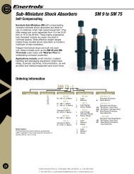
<strong>Standard</strong> <strong>Shock</strong> <strong>Absorbers</strong>SUB-MINIATURE, NON-ADJUSTABLE, FULL-THREADED BODY SERIESNEW!Enertrols NEW SM 9, SM 10,SM 25 and SM 75 Sub-MiniatureSelf-Compensating SeriesENERTROLS new durable line of Sub-Miniature non-adjustable shock absorbers offers highenergyabsorption capability in confined spaces. The wide range of Effective Weightcapacities for these rugged black-oxide finished models permits the handling of a varietyof damaging impact load conditions. Dependable sub-miniature self-<strong>com</strong>pensating modelshocks offer smooth deceleration over a wide range of conditions. Applications for thesereliable units include; small linear slides, material handling and packaging equipment,small robotics, medical and office equipment. See pages 24, 27 & 29 for Energy CapacityRatings, <strong>com</strong>plete dimensional data and “How to Order” information.STANDARD & ARMOR LINE MINIATURE, NON-ADJUSTABLE,FULL THREADED-BODY SERIESEnertrols versatile, high-capacity, miniature, non-adjustable hydraulicshock absorbers offer true linear deceleration to protect relativelysmall, high-speed moving machines and equipment. <strong>Standard</strong>black oxide finish models and Armor Line models areidentical dimensionally and in their energy capacities.Accessories (see page 30) are the same for adjustableand non-adjustable models.These “self-<strong>com</strong>pensating” shocks are available in manydifferent Effective Weight ranges to solve a wide range ofsmall, but damaging impact problems. A built-in positivestop in this series prevents bottoming out damage andprovides a positive work-positioning point. See pages 24, 28& 31 for Energy Capacity Ratings, <strong>com</strong>plete dimensional dataand “How to Order” information.SERIES 150SERIES 225SERIES 450SERIES 600STANDARD & ARMOR LINE MINIATURE, ADJUSTABLE, FULL THREADED-BODY SERIESENERTROLS miniature, adjustable, hydraulic shock absorbers feature <strong>com</strong>pletely threaded bodies for almost unlimited mountingversatility. They permit mounting, in or through a threaded hole in the mounting structure, at almost any point along the shockabsorber body. <strong>Standard</strong> models feature an attractive black oxide finish. Armor Line models were developed for corrosiveapplications and have a thin, dense chrome-plated finish that is FDA approved. Both series are identical dimensionally and in energyabsorbing capacity. SA 30m and SA 35 models are some of the new additions to the Enertrols line.SA 35SA 1/4 x 1/2SA 30m<strong>Standard</strong> black oxide finish models may be installed using an optional universalmounting bracket (internally threaded) for foot or flange mounting. A jam nutlocks the bracket anywhere on the body. Positive stops built in all modelsprevent bottoming out the shock absorbers.All Enertrols threaded-body models feature a locking adjustment. Theyare shipped prefilled with hydraulic oil, ready to use with no externalpiping or <strong>com</strong>ponents required. See pages 24, 29 & 31 for EnergyCapacity Ratings and dimensional data plus “How to Order” information.Armor LineModel SALD 1 /2 x 1-SA3/4" Bore Model4575-310STANDARD MID-SIZE, THREADED-BODY, NON-ADJUSTABLE SERIES 33,45 & 64Enertrols larger Mid-Size Threaded-Body, Non-Adjustable, Self-Compensating shock absorbers aredesigned for higher capacities to a maximum Effective Weight capacity of 140,400 lbs. Four effectiveweight ranges are available per model. Threaded bodies permits mounting, in or through a threadedhole, in the mounting structure at almost any point on the black oxide finished body. Studmounting using the furnished jam nut is the simplest. All of the mounting accessoriesoffered for the Sub-Miniature series (above) are available for the Mid-Size shocks. Seepages 30-31 for Energy Capacity Ratings and dimensional data plus “How to Order”information for 32 different models
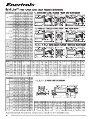
<strong>Standard</strong> <strong>Shock</strong> <strong>Absorbers</strong>Gold Line Series (SALD, ALD)Gold Line adjustable shock absorbers are re<strong>com</strong>mended for most deceleration applications, especially where it is desirable to usethe same model on a number of different installations. They perform well under a very wide window of conditions. For example,the weight range of these units is approximately 250:1, meaning maximum weight capacity can be as much as 250 times greaterthan minimum weight capacity. The adjustable fine-tuning feature provides maximum performance on virtually any application with avelocity ranging from 1-15 fps. By keeping impact forces to a minimum, they provide the softest stop, especially when critical and precisework-positioning is required.3/4" Bore Gold LinePrimary Mount<strong>Shock</strong> AbsorberAll mounting options for the Enertrols GoldLine and SILVERLINE Primary-MountSeries are shown here. From left to rightthey are: Front Flange, Clevis, BasicPrimary unit, Lug (Foot Mount) andRear Flange.PRIMARY MOUNTING TYPE 1 /2", 3 /4" & 1 1 /8" BORE SIZESThis larger series also features versatility of mounting through use of optionalaccessories that are threaded on either end of the shock absorber bodyand securely locked against a machined shoulder. Primary seriesunits are heavily used in environments that require a number ofdifferent style mountings of the same basic bore size and strokelength shock absorbers. See pages 34 & 35 for <strong>com</strong>pletedimensional data, Capacity Ratings and “How to Order” information.FIXED FLANGE MOUNTING TYPE 3 /4" THROUGH 3" BORE SIZESConventional Fixed Flange Enertrols shock absorbers have permanentlyattached front or rear flanges plus lug and clevis mount options. Theyare ideally suited for use by cost-conscious OEM’s using the samebasic shock absorber in large volume. Positive set-downpositioning when changing units is a major feature ofthis type. For <strong>com</strong>plete dimensional data, EnergyCapacity Ratings and “How to Order” informationsee pages 40, 41 & 43.HEAVY-DUTY 4" BORE ADJUSTABLE SHOCK ABSORBERSThese high-capacity Enertrols models <strong>com</strong>bine the features of both thePrimary and Fixed-Flange Series to offer an extremely versatile unit. Itoffers all standard mounting styles through the use of flanges that boltonto the ends of the body. Lug mounting bars are shown installed. With6", 8" and 16" strokes, this model can handle energies up to 1,600,000in.-lbs/cycle.These units are ideal for foundry, steel mill and similarheavy-duty applications. See page 42 for dimensional data, page 43for Energy Capacity Ratings and “How to Order” information.Gold Line4" Bore <strong>Shock</strong>Lug MountEquipped11
<strong>Standard</strong> <strong>Shock</strong> <strong>Absorbers</strong> for Special Applications3/4" & 1 1 /8", 1 1 /2” & 2 1 /4” BORE SILVERLINE SERIES FOR LOW-VELOCITY,HIGH EFFECTIVE WEIGHT APPLICATIONSEnertrols SILVERLINE Fixed Flange and Primary Mount Series adjustable shock absorbers aredesigned for <strong>com</strong>pact, high-energy automated equipment that operates at low velocities from0.25 to 2.0 feet/second coupled with high Effective Weight conditions. Most roboticinstallations involve rotary motion and shock absorbers are typically positioned nearpivot points for increased clearance and more room in the work area.Rotary Motion installations are almost always subjected to high EffectiveWeight conditions caused by low velocity. As a result, most of theenergy <strong>com</strong>es from the propelling force instead of inertia. Theseconditions usually meant ordering special shocks with larger bore sizes,stop tubes and heavier oils, resulting in longer lead times and higherprices. With SILVERLINE shock absorbers, it is no longer necessary toorder special models. Enertrols solves these problems with lower-cost,standard, off-the-shelf products.SILVERLINEPrimary Mount<strong>Shock</strong> Absorberwith Rear FlangeAny application position (rotary, vertical, horizontal and incline) where low velocity and higheffective weight exists, is an excellent application for Enertrols SILVERLINE shock absorbers. They are designed to operate in avelocity range of 0.25 to 2.0 fps and in an effective weight range of 300 lbs to 3,175,000 lbs maximum. All models use standardweight hydraulic oil for fast rod return on high cycling applications.SILVERLINE shock absorbers <strong>com</strong>e in four bore sizes and two stroke lengths. Primary Mount models are available in 3/4” and1 1 /8” bore sizes only; Fixed Flange models are available in all bore sizes. <strong>Standard</strong> accessories include flanges, lugs, clevises,Mounting and Positive Stop collars and bars, proximity switches, air-oil tanks and soft pads. Extra-high temperature seals andcoatings are also available. For detailed drawings and dimensions and “How to Order” information, see pages 44 & 45.19mm & 28mm BORE HIGH-PRECISION METRIC (HPM) FIXED FLANGE SERIESThis new series of Fixed-Flange adjustable shock absorbers is rapidly be<strong>com</strong>ing an internationalautomotive standard. They provide an exceptional high-positioning accuracy - positive set-downpositioning repeatable within +/- .05mm - with easy “bolt-in place” installation. They areinterchangeable with all Enertrols Gold Line Primary Mount shock absorbers withscrew-on flanges and all standard Enertrols Gold Line welded flange models, aswell as other manufacturers models of the same bore size.Precision-built to “Hard Metric Mounting” standards, the new shocks are a trulyinternational standard for use on automated machinery and equipment anywherein the world. Welded Front-Flange models are factory equipped with EnertrolsPositive Stop Bars; Welded Rear Flange models are equipped with EnertrolsPositive Stop Collars. There are 14 Models available in two mountingconfigurations, two bore sizes and three stroke lengths. Four models areavailable for Low-Velocity applications (0.25 to 2.0 fps). They are all availablefrom stock with sales and service available World-wide.Enertrols HPM shock absorbers let you: eliminate cost to design and build externalstops; eliminate expensive shim packs required for precision adjustment; eliminate adjustingcostly external stops, proximity sensors and limit switches; and prevent damage caused bybottoming the shock absorber piston. See page 46 for dimensioned drawings, EnergyCapacities and “How to Order” information.HPM 19mm BoreMetric <strong>Shock</strong> withWelded Front Flangeand Positive Stop Bars12
<strong>Standard</strong> <strong>Shock</strong> <strong>Absorbers</strong> for Special Applications3/4" THROUGH 4" BORE PROX SHOCK SERIESENERTROLS “Prox <strong>Shock</strong>”, end-of-stroke sensing, adjustable, hydraulic shock absorber, features an on-board proximitysensor that simplifies the design and fabrication of today’s automation equipment. Combining anelectronic proximity switch with the latest shock absorber technology eliminates cumbersomeand troublesome limit switches that constantly need adjustment. The device offers industrya simple, reliable way to produce an electronic signal capable of interfacing with<strong>com</strong>puter-controlled automation equipment.3/4" Bore PrimaryMount Gold LineProx <strong>Shock</strong> equippedwith Enertrols Mounting StopCollar (MSC) and end-ofstrokesensing Proximity Sensor.The Prox <strong>Shock</strong> is available in both Primary-Mount and Fixed-Flange models.It is normally intended to be used as a front-mounted shock absorber, orin <strong>com</strong>bination with the ENERTROLS Mounting Stop Collar (shown).When coupled with the MSC, the Prox <strong>Shock</strong> gives the user themost economical, easy-to-install and tamper-proof system forproviding a positive stop or work-position point, plus on-boardproximity sensing that requires no additional adjustments ormaintenance.2 1 /4" BORE LONG-STROKE SHOCK ABSORBERSENERTROLS special design Long-Stroke Models are non-adjustable shock absorbers. They offer a variable, self-<strong>com</strong>pensatingload capacity for each individual application. Six stroke lengths are available.A major application for these units has been on <strong>com</strong>puterized stacking cranes in special warehouseretrieval systems. The shock absorber serves as a safety backup in the event the<strong>com</strong>puterized speed control should fail for any reason. For details,consult your local representative, or the factory.1 1 /8" BORE QUICK-CHANGE MOUNT SHOCK ABSORBERENERTROLS patented QCM (Quick-Change Mount) adjustablehydraulic shock absorber is designed to directly replace existingshock absorbers on horizontal extractors, shuttles, loadersand unloaders. Easy, fast removal and reinstallation of theQCM shock is its major feature.Since it is a true linear decelerator, the QCM unit reducesdeceleration time and increases cycle rates. It also reduces impactforces at the end-of-stroke, even with today’s high shuttle speeds.There are no threads to nick or trap weld flash and other contaminants.13
Accessories & Special Application <strong>Shock</strong> <strong>Absorbers</strong>SOFT PADSEnertrols Soft Pads (shown installed on a 3 /4"-bore Gold Line Primary Mount shock absorber)are available in five sizes to fit securely over the piston rod button of all 3 /8", 1 /2", 3 /4", 1 1 /8"and 1 1 /2" bore-size models. They are made of tough, long-wearing polyurethane toreduce noise and/or marring of the object impacting on the steel button.STANDARD AIR-OVER-OIL TANKSEnertrols Air-over-Oil Tanks (AOT) are available in the four stock sizes shown foruse with all ALD and ALDS models, 1 /2" through 4"-bore sizes. The three largesttanks are made of high-strength steel, use no soft seals and have easy-to-readsight gauges. See page 47 for detailed dimensions.2 1 /2" BORE TOW BAR SNUBBERSENERTROLS Tow Bar Snubber is a 2 1 /2" bore, non-adjustablepneumatic shock absorber specially adapted for use on highspeedmaterial handling systems. The higher speeds beingused on today’s power and free handling systems greatly increasethe potential for both product and/or system damage due to the rapidacceleration/deceleration speeds generated.The Tow Bar Snubber is designed to absorb and smooth rapid acceleration/deceleration whenstarting and stopping. This prevents stretching and <strong>com</strong>pressing load conditions to reduce maintenanceand increase “up-time” of the material handling system. The unit will handle conveyor speedsup to 80 feet/minute with loads up to 6,000 Ibs, maximum. Tensile load limit is 40,000 pounds.ENERTROLS Tow Bar Snubbers are available in 4" and 6" stroke lengths. They feature hightemperatureseals, extra-long rod bearings and strong chrome-plated piston rods.These units are easily repaired in the field.Reverse SnubberAir/HydraulicThe Enertrols Reverse Snubber (Pat. Pend.) is installed with theclevis end of the piston rod fastened to a fixed point. Theopposite end of the body is clevised to the moving load andmoves with the load as the piston strokes. This eliminates pistonrod boots and covers to prevent contamination damage to the rod.SPECIAL-PURPOSE NON-ADJUSTABLE SHOCK ABSORBERSEnertrols builds non-adjustable shock absorbers such as this unit for use in a state-of-the-artamusement ride. They feature a self-<strong>com</strong>pensating load capacity, using an inner metering tubeselected for the application. The shock absorbers must safely decelerate the ride, and itspassengers, under constantly changing loads and velocities since the number ofriders may vary widely. Many industrial applications, involving the sameconditions, make use of this custom-orificed, special Enertrols design.14
PSS Positive Stop Systemsfor Gold Line & SILVERLINE <strong>Shock</strong> <strong>Absorbers</strong>MOUNTING STOP COLLARSENERTROLS Mounting Stop Collar (MSC), shown installed on a Gold Line Primary-Mount Series shock absorber. The MSC provides a secure front mounting with anintegral, tamperproof positive stop. The FSC Flanged Stop Collar (not shown)provides a front flange type mount with an integral positive stop. Available to fit allGold Line and SILVERLINE Primary-Mount Models. See page 38 for details.PositiveStop CollarPOSITIVE STOP COLLARSPOSITIVE STOP BARS AND COLLARSENERTROLS Positive Stop Collar (PSC), shown installed on a Gold Line Primary-MountSeries (also for SILVERLINE Primary-Mount Models). It is not used to mount the unit,but only to establish a fixed, tamperproof work-positioning point that also provides apositive stop to protect the shock absorber from bottoming out. You do not need tocalculate clearance to prevent bottoming out. It’s automatic! See page 38 for details.Enertrols is the only manufacturer of stop collars and stop bars that are hardened toRc 55-58 as a <strong>Standard</strong> procedure. This applies to all variations, including Mounting StopCollars, Positive Stop Collars, Flanged Stop Collars and Positive Stop Bars.ENERTROLS Positive Stop Collars and Bars establish a fixed work-positioning point with no need to calculate clearance toprevent bottoming out of Gold Line Fixed Flange and SILVERLINE Fixed Flange shock absorbers. Theyare not used to mount the shock absorber. The precision-machined and hardened steel bars are securelybolted to the flange.PositiveStop BarsAccessories for PSS SystemsPositive Stop Collars for Fixed Rear Flange models fit snuglyover the front of the shock absorber body. Set screwssecure the collar after a recessed shoulder islocated against the shock absorber. This collaralso aids in protecting the return spring, rodand seals from weld spatter, metal chips andother contaminants. See page 41 for <strong>com</strong>pletedetails and specifications.STANDARD MOUNTING PLATES AND BRACKETSPositiveStop CollarEnertrols <strong>Standard</strong> Mounting Plates and Brackets save time and money by reducing design and fabrication costs whenever youhave an installation requiring them. They are used with Primary Mount shock absorbers toassure correct mounting structure thickness and location of all mounting holes. Finishmachined both sides for exact dimensional positioning. Available to fit all primary 1 /2", 3 /4"and 1 1 /8" bore sizes. See page 35 for details.Shown here is a Gold Line shock absorber secured in a standard MountingBracket by an ENERTROLS Mounting Stop Collar (MSC). An optionalENERTROLS Retaining Kit insures that the work-positioning point of thepositive stop will not belost due to improperinstallation ortampering. See page39 for details.MountingStop Collar15
Selecting the Correct Type of <strong>Shock</strong> AbsorberBefore beginning the mathematical calculations to determinethe correct size shock absorber you need, Enertrols suggestsfirst considering the Type, or Style, and options that will bebest suited to your application.BASIC TYPES:A. Miniature Full Threaded-Body SeriesB. Primary Mounting SeriesC. Fixed Flange Mounting SeriesFULL THREADED-BODY TYPEThese shock absorbers offer real mounting versatility. Stud mounting,in or through a threaded hole; universal mounting brackets, threadedon and locked anywhere on the body; and clevis-type fittings let youinstall these miniature units almost anywhere. Available in bothadjustable (SALD) and non-adjustable (SNALD) models. A choice ofblack oxide finish (<strong>Standard</strong>), or protective satin finish (Armor Line)for corrosive applications, is also offered.PRIMARY MOUNTING TYPEThis larger series also features versatility of mountingthrough use of optional accessories that are threaded oneither end of the shock absorber body and securely lockedagainst a machined shoulder. Primary series units areheavily used in environments that require a number ofdifferent style mountings of the same basic bore size andstroke length shock absorbers.FIXED FLANGE MOUNTING TYPEConventional fixed flange Enertrols shock absorbers havepermanently attached flanges. They are ideally suited foruse by cost-conscious OEM’s using the same basic shockabsorber in large volume. Positive set-down positioningwhen changing units is a major feature of this type.TYPE OF MOUNTINGEnertrols shock absorbers are available in a number of mounting configurations to meet most any need. For fixed flange seriesyou must specify front or rear mount flanges, which are available in square, rectangular, lug or clevis-type choices. Primaryseries do not require choice of front or rear mounting since you may thread flanges on either end.TYPE OF ACCUMULATORInternal accumulators are the most widely used and permit immediate installation and use with no piping or fitting required.High cycle rates and/or extremely high energy requirements may require an external accumulator for cooling the oil byrecirculating it outside the shock absorber body.TYPE OF ROD RETURNSpring return piston rods, used with internal accumulators, are the most <strong>com</strong>mon type. Air (or mechanical) returns, used withexternal accumulators, permit delayed rod return type installations where required.TYPES OF OPTIONSCertain types of options should also be selected at this time. Positive Stop Collars, Mounting Stop Collars and Positive StopBars (see pages 30, 38 & 41) have been among Enertrols fastest growing options items. They provide a unique, tamperproofpositive stop that establishes an accurate work-positioning point. These attachments also prevent impact damage that might becaused by bottoming the shock absorber piston. As standard, stock items, they also eliminate the cost to design and fabricateexternal positive stops into your system.Soft pads, molded polyurethane pads that snap over the hardened steel impact button of our shock absorbers, prevent marringof the object being stopped and help to reduce noise.On-board proximity sensors are available for most of the shock absorbers in the Enertrols line (see page 13). Theyelectronically signal the end-of-stroke, or home position, of the piston rod to control interlocking motions, devices, etc.16
Selecting the Correct Model <strong>Shock</strong> AbsorberThe Model type of an Enertrols shock absorber is determined by:■ Type of accumulator—self-contained or external air/oil tank(AOT)■ Method of piston rod return—spring, air, or mechanicalModel and mounting selection are usually determined by theapplication. Self-contained models are generally preferredover the external accumulator-equipped models. They arepre-filled at the factory and ready to use when received. Noexternal piping or other system <strong>com</strong>ponents are required.Because Enertrols shocks stop a moving object in less timethan non-linear decelerating devices, you should select a unitwith the longest possible stroke that can be ac<strong>com</strong>modated(without exceeding side-loading limits; see page 48). This willminimize impact forces on the mounting structure and themoving object being stopped.ACCUMULATORSBASIC MODEL DESIGNATIONSType ofMethod ofAccumulator Piston Rod ReturnModelInternal Spring SAInternal Spring SALDExternal Air (or Mechanical) ALDInternal Mechanical ALDAExternal Spring ALDSInternal Spring (non-adjustable) SMInternal Spring (non-adjustable) SNALDExternal Air or Mech. (non-adjustable) NALDInternal Spring (SILVERLINE) SASLExternal Air (SILVERLINE) ASLExternal Spring (SILVERLINE) ASLSInternal Mechanical (SILVERLINE) ASLAWith internal accumulator models, the fluid displaced by the piston rod under impact is forced against a nitrogen-filled, closedcellsponge in the body of the shock absorber. As the piston rod is returned, the sponge expands to help force fluid back intothe high-pressure tube. Where conditions permit, internal accumulator models are preferred.Where more energy per hour (E 4), or heat dissipation is needed, as found in high duty-cycle applications, or high-temperatureenvironments, external accumulator models should be used. The external accumulator is a tank or reservoir, either open orclosed to atmosphere, that is connected to the shock absorber with appropriate size piping. The oil flows back and forthbetween it and the shock absorber, helping to cool the oil as the unit is cycled. The air/oil tank (AOT) of external accumulatorequippedmodels must be above the shock absorber and should be located as close to the shock absorber as possible.A 10-micron filter, installed between the exit of the air/oil tank and the shock absorber, is re<strong>com</strong>mended.If the AOT must be located at a substantial distance from the shock use a positive oil recirculation circuit (Fig. 2B).Otherwise, oil may simply move back and forth in the lines and never reach the tank to be cooled.PISTON ROD RETURNThe return of the piston rod is ac<strong>com</strong>plished in one of three ways (spring, air/oil, or mechanically). Mechanical returns usuallymake use of clevis-mounting designs and may be operated by a lever arm actuated by some other moving part of theequipment. On self-contained models, or air/oil models with a spring, an externally mounted spring returns the rod when theload is removed.In external accumulator models, an air/oil system, or some other mechanical means, must be used to return the piston rod.ALD models permit a variable rate of rod return, time delay and/or lower rod return forces. This is ac<strong>com</strong>plished by adding apressure regulator (Fig. 2B) to the air/oil system, or by addingFIGURE 2a 3-way valve and pressure regulator (Fig. 2C) to the system.ALDS models are shipped with a rod return spring installed.Thus, even when an external accumulator is used to improve heatdissipation, it need not be pressurized. The spring will providethe necessary rod return force. For best results, the accumulatorshould be vented to atmosphere with a filter/breather unit.A B CRe<strong>com</strong>mended air pressure for air oil tanks is 70-100 psidepending on the application.All mounting options for theEnertrols Gold Line andSILVERLINE Primary MountSeries are shown here. From left toright they are: Front Flange, Clevis,Basic Primary, Lug (Foot Mount)and Rear Flange.17
Selecting the Correct Size <strong>Shock</strong> AbsorberThere are a number of factors that must be considered when selecting a hydraulic shock absorber. First, determine how muchenergy must be dissipated during each deceleration stroke (cycle). Second, find the total amount of energy that must bedissipated during one hour of operation. Third, be sure to consider the Effective Weight of your application.The formulas used to determine the amount of kinetic energy per cycle are derived from the equation KE = 1 /2MV 2 . When used inthe form KE = 0.2WV 2 , the equation yields an answer in inch-lbs that can be correlated directly to the shock absorber EnergyRating Charts on pages 24-26. A moving object’s energy will always consist of either pure inertia, or a <strong>com</strong>bination of that inertiaand a propelling force.Sub-Miniature and Miniature full threaded-body adjustable shock absorbers are ideal for small,motor-driven, linear applications such as business machines (copiers, scanners & printers).Enertrols Primary Mounting Series shocks are our most widely used modelsbecause of their versatility and energy capacity ratings. You can install themalmost anywhere and handle impact loads from 10 to 150,000 lbs ofEffective Weight.You might think slow-moving loads (less than 2 ft,/second)wouldn’t present much of a shock problem. Not so! In factthey are one of the toughest to handle. Most applicationsinvolving rotary motions are slow movers. Enertrolsdeveloped its SILVERLINE Series especially for theseapplications. You’ll find them on pages 44 & 45.When you need heavy-duty, Enertrols Gold LineFixed Flange shocks are your answer. Some modelscan handle up to about two-million lbs. of Effective Weight. You’ll find a lot of themon vertical (and horizontal and inclined plane) free-falling applications. Completedetails on pages 40-43.BASIC FORMULASE1 = 0.2WV 2 (or W x H for free-falling objects) in.-lbs.E2 = F x S (or W x S for free-falling objects) in.-lbs.E3 = E1 +E2 in.-lbs.E4 = E3 x C (cycles/hour) in.-lbs./hr.V = √5.36 x H determines velocity of free-falling object–ft./sec.g = .2 x V 2 to determine G force, or stroke (S)SV = Dis in feet to determine impact velocity whent weight is moving at a constant speedover a distance – ft./sec.V =2 x Dis in feet to determine impact velocity whent weight is accelerating over a distancefrom a stopped position – ft./sec.F = D 2 x .78 x PSI to determine cylinder force in poundsF = 1375 x HP to determine Propelling Force in poundsV when using an Electric Motort = S stopping time through stroke6VENERGY CALCULATION SYMBOLSt = Time in secondsS = <strong>Shock</strong> absorber stroke in inchesRS = Radius to shock absorber in inchesRC = Radius to cylinder in inchesK = Radius to center of gravity (c.g.)V = Impact velocity in feet/secondg = Deceleration in G’sD = Diameter in inchesDis = Distance in feetW = Weight in pounds (Ibs.)WE = Effective Weight (lbs.)H = Height in inches (in.)F = Propelling Force (Ibs.)C = Cycles per hourE1 = Inertial energy (in.-lbs/cycle)E2 = Propelling Force energy (in.-lbs./cycle)E3 = Total energy per cycleE4 = Total energy to be dissipated per hourPSI = Pressure (pounds per square inch)HP = HorsepowerT = Torque (in.-Ibs.)L = Distance (in.)18
EFFECTIVE WEIGHTThe determination of Effective Weight has be<strong>com</strong>e an importantfactor in correctly sizing a shock absorber. Effective Weight willindicate if the shock absorber can be adjusted to performproperly. It prevents improper selection (over or under sizing)where propelling forces are involved, or velocities are very lowor very high.A rough “rule of thumb” frequently used is to select the nextlarger bore size when impact velocities are below 1 ft/sec and/orpropelling force energy (F x S) exceeds 1 /2 of the E 3 value, ascalculated. Or, you may want to use an Enertrols SILVERLINEshock absorber if your requirements permit short-strokemodels. If in doubt, contact your local rep, or the factory foradditional sizing information.However, high Effective Weight generates high set-down force atthe end of the shock absorber stroke. Low Effective Weights cancause very high impact forces at the beginning of the stroke.These conditions must be considered for they may lead to severedamage over a period of time. All Enertrols shock absorbers carryEffective Weight ratings (See charts on pages 24-26). EffectiveWeight is calculated using the equation:WE =E3orE30.2V 2 Hforfree-falling{ objectsAs an example of how to calculate and use EffectiveWeight in sizing an Enertrols shock absorber, consider thefollowing examples:EXAMPLE 1Vertical Free-Falling WeightW = 1800 lbsH = 40 inchesC = 200/hourS = 8 inches**Selected strokeCalculations:E1 = W x H = 1800 x 40 = 72,000 in.-lbsE2 = W x S = 1800 x 8 = 14,400 in.-lbsE3 = E1 + E2 = 72,000 + 14,400 = 86,400 in.-lbsE4 = E3 x C = 86,400 x 200 = 17,280,000 in.-lbs/hourWE = E3 = 86,400 = 2,160 lbs.H 40V = √5.36 x H = √5.36 x 40 = 14.6 feet/secondFrom the Rating Chart (page 26), select an Enertrols Model SALD2 x 8 shock absorber. This unit will handle the energy per cycle and energy per hour requirements of the application. It also meetsEffective Weight requirements. Following are a variety of examples selected to represent the most widely used installations of Enertrolsshock absorbers. Although the calculations may look formidable at first glance, they are actually quite simple to use. When you have anew application, just substitute your numbers in the example that <strong>com</strong>es closest to your own. If you think you need additional help,contact your Enertrols representative, or call the factory. There is no obligation.FALLINGHEIGHT(W)WEIGHT(V) VELOCITYSTROKEEXAMPLE 2Vertical Load Propelled DownwardEXAMPLE 3Vertical Load Propelled UpwardCYLINDER:BORE DIA.(W) WEIGHTPRESSUREW = 950 lbs.V = 4 ft./sec.Cyl. Dia. = 2 in.PSI = 80S = 4 in.*C = 100/hr.SHOCK ABSORBERSTROKE (INCHES)(V) VELOCITYW = 950 lbsV = 4 ft./sec.Cyl. Dia. = 4 in. (2 cyl. used)PSI = 80S = 4 in.*C = 100/hr.(V) VELOCITYW=WEIGHT (LBS)SHOCK ABSORBERSTROKE (INCHES)CYLINDER:BORE DIA.2CYLINDERSPRESSUREE1 = .2WV 2 = .2 x 950 x (4) 2 = 3,040 in.-lbs.F = Cyl. Force = .78 x D 2 x PSI = .78 x 2 2 x 80 = 250 lbs.E2 = (F + W) x S = (250 + 950) x 4 = 4,800 in.-lbs.E3 = E1 + E2 = 3,040 + 4,800 = 7,840 in.-lbs.E4 = E3 x C = 7,840 x 100 = 784,000 in.-lbs./hr.WE= E3 = 7,840 = 2,450 lbs..2V 2 .2(4) 2Model Selection: SALD 1 1 /8 x 4E1 = .2WV 2 = .2 x 950 x (4) 2 = 3,040 in.-lbs.F = Cyl. Force = 2(.78 x D 2 x PSI) = 2(.78 x 4 2 x 80) = 1,997 lbs.E2 = (F - W) x S = (1,997 - 950) x 4 = 4,188 in.-lbs.E3 = E1 + E2 = 3,040 + 4,188 = 7,228 in.-lbs.E4 = E3 x C = 7,228 x 100 = 722,800 in.-lbs./hr.WE= E3 = 7,228 = 2,259 lbs..2V 2 .2(4) 2Model Selection: SALD 1 1 /8 x 4*Note: These items will vary with individual applicationsand were selected for illustration purposes only.19
EXAMPLE 4Moving Load No Propelling Force(W) WEIGHT(V) VELOCITYSTROKE(INCHES)E1 = .2WV 2 = .2 x 1,950 x 5 2 = 9,750 in.-lbs.E2 = 0E3 = E1 + E2 = 9,750 in.-lbs.E4 = E3 x C = 9,750 x 200 = 1,950,000 in.-lbs./hr.WE= E3 = 1,950 lbs..2V 2Model Selection: SALD 1 1 /8 x 4W = 1,950 lbs.V = 5 ft./sec.F = 0C = 200/hr.EXAMPLE 5Moving Load With Propelling ForcePRESSURECYLINDER: BORE DIA.(W) WEIGHT(V) VELOCITYSTROKE(INCHES)E1 = .2WV 2 = .2 x 1,950 x 5 2 = 9,750 in.-lbs.F = Cyl. Force = .78 x D 2 x PSI = .78 x (2) 2 x 80 = 250 lbs.E2 = F x S = 250 x 2 = 500 in.-lbs.E3 = E1 + E2 = 9,750 + 500 = 10,250 in.-lbs.E4 = E3 x C = 10,250 x 100 = 1,025,000 in.-lbs./hr.WE= E3 = 10,250 = 2,050 lbs..2V 2 .2(5) 2Model Selection: SALD 1 1 /8 x 2W = 1,950 lbs.V = 5 ft./sec.Cyl. Dia. = 2 in.PSI = 80S = 2 in.*C = 100/hr.EXAMPLE 6Moving Load Motor DrivenEXAMPLE 7Moving Load Propelled by Drive Rollers(Chain/Belt Drive Conveyor)(V) VELOCITY(W) WEIGHTMOTOR RATING HPSTROKEW = 1,950 lbs.V = 5 ft./sec.HP = 1 HorsepowerS = 2 in.*C = 100/hr.(W) WEIGHT(V) VELOCITYCOEFFICIENT OF FRICTIONSTROKEW = 1,950 lbs.V = 5 ft./sec.F = Coefficient of friction x WCoefficient of frictionin this example = .18S = 2 in.*C = 100/hr.E1 = .2WV 2 = .2 x 1,950 x 5 2 = 9,750 in.-lbs.F = 1,375 x HP = 1,375 x 1 = 275 lbs.V 5E2 = F x S = 550 in.-lbs.E3 = E1 + E2 = 9,750 + 550 = 10,300 in.-lbs.E4 = E3 x C = 10,300 x 100 = 1,030,000 in.-lbs./hr.WE= 10,300 = 2,060 lbs..2V 2Model Selection: SALD 1 1 /8 x 2E1 = .2WV 2 = .2 x 1,950 x 5 2 = 9,750 in.-lbs.E2 = F x S = (.18 x W) x 2 = 702 in.-lbs.E3 = E1 + E 2 = 9,750 + 702 = 10,452 in.-lbs.E4 = E3 x C = 10,452 x 100 = 1,045,200 in.-lbs./hr.WE= E3 = 10,452 = 2,090 lbs..2V 2 .2(5) 2Model Selection: SALD 1 1 /8 x 2EXAMPLE 8Moving Load Down an Inclined Plane(W) WEIGHTAºDISTANCE(INCHES)STROKEE1 = W x Sin A x L = 1,950 x .26 x 30 = 15,210 in.-lbs.E2 = W x Sin A x S = 1,950 x .26 x 2 = 1,014 in.-lbs.E3 = E1 + E2 = 15,210 + 1,014 = 16,224 in.-lbs.E4 = E3 x C = 16,224 x 100 = 1,622,400 in.-lbs./hr.Vs = √5.36 x (SinA) x L = √5.36 x .26 x 30 = 6.4 ft./sec.WE= E3 = 16,224 = 1980 lbs..2Vs 2 .2(6.4) 2Model Selection: SALD 1 1 /2 x 2Note: These items will vary with individual applications*and were selected for illustration purposes only.W = 1,950 lbs.Angle of Incline = 15°L = Distance traveled= 30 in.S = 2 in.*C = 100/hr.EXAMPLE 9Horizontal–Moving Load–RotaryDISTANCE FROMPIVOTTO CENTEROF GRAVITY(INCHES)WEIGHTSHOCK ABSORBERMOUNTING RADIUS(INCHES)Velocity of Load = A x K = 90 x 30 = 1.31 ft./sec.688t 688 x 3E1 = .2WV 2 = .2 x 900 x (1.31) 2 = 309 in.-lbs.E2 = 0E3 = E1 + E2 = 309 in.-lbs.E4 = E3 x C = 309 x 100 = 30,900 in.-lbs./hr.VS = A x RS = 90 x 29 = 1.26 ft./sec.688t 688 x 3WE= E3 = 309 in.-lbs. = 973 lbs..2Vs 2 .2(1.26) 2Model Selection: SALD 1 /2 x 1K = Distance to C.G.from Pivot = 30 in.W= 900 lbs.A = Rotation angle = 90°t = Time thru angle = 3 sec.RS= <strong>Shock</strong> absorber mtg.radius = 29 in.F = 0S = 1 in.*C = 100/hr.VS = Vel. @ RS (ft./sec.)20
EXAMPLE 10Horizontal–Propelled Moving Load–RotaryMOTOR DRIVETORQUE(V) VELOCITYEXAMPLE 11Horizontal–Rotary Index Table(W) TABLEWEIGHTROTARY TABLE DIA.DISTANCE FROMPIVOT TO CENTEROF GRAVITYSHOCK ABSORBERMOUNTING RADIUS(INCHES)SHOCK ABSORBERMOUNTINGRADIUS (INCHES)WEIGHTE1 = .2WV 2 = .2 x 900 x 4 2 = 2,880 in.-lbs.VS = V x RS = 4 x 29 = 3.87 ft./sec.K 30F = 1,375 x HP = 1,375 x 1 = 355 lbs.VS 3.87E2 = F x S = 355 x 2 = 710 in.-lbs.E3 = E1 + E2 = 2,880 + 710 = 3,590 in.-lbs.E4 = E3 x C = 3,590 x 100 = 359,000 in.-lbs./hr.WE= E3 = 3,590 = 1,199 lbs..2Vs 2 .2(3.87) 2Model Selection: SALD 3 /4 x 2W= 900 lbs.K = Distance to C.G.from Pivot = 30 in.V = Linear velocityat C.G. = 4 ft./sec.RS= 29 in.S = 2 in.*C = 100/hr.HP = 1 HorsepowerVS= Vel. @ RS (ft./sec.)E1 = .1WVT 2 = .1 x 900 x 4 2 = 1,440 in.-lbs.E2 = 0E3 = E1 + E2 = 1,440 in.-lbs.E4 = E3 x C = 1,440 x 100 = 144,000 in.-lbs./hr.VS = VT x RS = 4 x 30 = 3.3 ft./sec.RT 36ANGULAR VELOCITY(RADIANS/SEC.)WE= E3 = 1,440 = 661 lbs..2Vs 2 .2(3.3) 2Model Selection: SALD 1 /2 x 2STROKEW= 900 lbs.VT= 4 ft./sec. at 36 in.from PivotC = 100/hr.F = 0RS= 30 in.DT= Table Dia. = 72 in.RT= 36 in.VS= Vel. @ RS (ft./sec.)EXAMPLE 12Horizontal–RotaryIndex Table–PropelledMOTOR DRIVETORQUEROTARY TABLE DIA.(W) TABLE WEIGHTRTEXAMPLE 13Vertical–RotaryDISTANCE FROMPIVOT TO CENTEROF GRAVITY(INCHES)VT = ω x RT = 2 x 36 = 6 ft./sec.12 12E1 = .1WVT 2 = .1 x 900 x 6 2 = 3,240 in.-lbs.F = T = 1,500 = 50 lbs.RS 30ANGULAR VELOCITYE2 = F x S = 50 x 2 = 100 in.-lbs.E3 = E1 + E2 = 3,240 + 100 = 3,340 in.-lbs.E4 = E3 x C = 3,340 x 100 = 334,000 in.-lbs./hr.VS = ω x RS = 2 x 30 = 5 ft./sec.12 12WE= E3 = 3,340 = 668 lbs..2Vs 2 .2(5) 2Model Selection: SALD 3 /4 x 2ωRSSHOCK STROKE(INCHES)SHOCK ABSORBERMOUNTINGRADIUS (INCHES)W= 900 lbs.ω= 2 Radians/sec.T = 1,500 in.-lbs. at tableS = 2 in.*C = 100/hr.RS= 30 in.RT= Radius of table = 36 in.VS= Vel. @ RS (ft./sec.)E1 = .2WV 2 = .2 x 500 x 4 2 = 1,600 in.-lbs.F = W x K = 500 x 34 = 531 lbs.RS 32WEIGHTE2 = F x S = 531 x 2 = 1,062 in.-lbs.E3 = E1 + E2 = 1,600 + 1,062 = 2,662 in.-lbs.E4 = E3 x C = 2,662 x 100 = 266,200 in.-lbs./hr.VS = V x RS = 4 x 32 = 3.76 ft./sec.K 34WE= E3 = 2,662 = 941 lbs..2Vs 2 .2(3.76) 2Model Selection: SALD 3 /4 x 2SHOCK ABSORBERMOUNTINGRADIUS (INCHES)STROKE(INCHES)W= 500 lbs.K = Distance to C.G. = 34 in.V = 4 ft./sec. @ 34 in.RS= <strong>Shock</strong> absorber mtg.radius = 32 in.S = 2 in.*C = 100/hr.VS= Vel. @ RS (ft./sec.)EXAMPLE 14Vertical–Rollover–Turn OverROTATIONPARTVELOCITYEXAMPLE 15HorizontalApplication–Moving Load–Rotary TableMotor Drivenwith AdditionalLoad InstalledDRIVETORQUE(T)(W)WEIGHTANGULARVELOCITYRLRTSHOCKSTROKEWLRSROLLOVERVR = RR x A = 60 x 180 = 5.24 ft./sec.688t 688 x 3E1 = .1WVR 2 = .1 x 1,500 x 5.24 2 = 4,119 in.-lbs.F = T = 12,000 = 194 lbs.RS 62E2 = F x S = 194 x 2 = 388 in.-lbs.E3 = E1 + E2 = 4,119 + 388 = 4,507 in.-lbs.E4 = E3 x C = 4,507 x 100 = 450,700 in.-lbs./hr.VS = RS x A = 62 x 180 = 5.4 ft./sec.688t 688 x 3WE= E3 = 4,507 = 772 lbs..2Vs 2 .2(5.4) 2Model Selection: SALD 1 1 /2 x 2Note: These items will vary with individual applications*and were selected for illustration purposes only.W = 1,500 lbs.A = 180° Angle of RotationRS = 62 in.T = 12,000 in.-lbs.S = 2 in.*C = 100/hr.RR = 60 in. Radius of RolloverVR = Vel. @ RR (ft./sec.)VS = Vel. @ RS (ft./sec.)t = 3 sec. Time of RotationVT = ω x RT = 1 x 20 = 1.67 ft./sec.12 12E1 (TABLE) = .1WVT 2 = .1 x 440 x 1.67 2 = 123 in.-lbs.VL = ω x RL = 1 x 8 = .67 ft./sec.12 12E1 (ADD’L LOAD) = .2WLVL 2 = .2 x 100 x .67 2 = 9 in.-lbs.E1 (TOTAL) = E1 (TABLE) + E1 (ADD’L LOAD) = 123 + 9 = 132 in.-lbs.F = T = 2,200 = 248 lbs.RS 8.86E2 = F x S = 248 x 1 = 248 in.-lbs.E3 = E1 + E2 = 132 + 248 = 380 in.-lbs.E4 = E3 x C = 380 x 1 = 380 in.-lbs./hr.VS = ω x RS = 1 x 8.86 = .74 ft./sec.12 12WE= E3 = 380 = 3,470 lbs..2Vs 2 .2(.74) 2Model Selection: SALD 3 /4 x 1 (Due to Effective Weight)W = 440 lbs.WL= Additional weight= 100 lbs.RL= Radius to load C.G.from pivot – 8 in.*S = 1 in.*C = 1/hr.ω= 1 radian/sec.RS= 8.86 in.T = 2,200 in.-lbs.RT= 20 in.VT= Vel. @ RT (ft./sec.)VL= Vel. @ RL (ft./sec.)VS= Vel. @ RS (ft./sec.)21
EXAMPLE 16Vertical–Rotating Beam Driven by Air CylinderωI = W x K 2 = 1,900 x 20 2 = 1,969 in.-lbs./sec. 2386 386F = .78 x D 2 x PSI x RC = .78 x 3 2 x 70 x 18 = 276 lbs.RS 32E1 = I x ω 2 = 1,969 x 3 2 = 8,861 in.-lbs.2 2E2 = F x S = 276 x 2 = 552 in.-lbs.E3 = E1 + E2 = 8,861 + 552 = 9,413 in.-lbs.E4 = E3 x C = 9,413 x 100 = 941,300 in.-lbs./hr.VS = .083 x RS x ω = .083 x 32 x 3 = 8.00 ft./sec.WE= E3 = 9,413 = 735 lbs..2Vs 2 .2(8) 2Model Selection: SALD 1 1 /8 x 2SRCKRSCyl Dia. = 3 in.PSI = 70ω= 3 rad./sec.W= 1,900 lbs. at C.G.K = 20 in. to beam C.G.S = 2 in.*C = 100/hr.RS= 32 in.VS= Vel. @ RS (ft./sec.)RC= 18 in.EXAMPLE 17Vertical–Motor DrivenRotating Arm withAttached LoadOpposing GravityI = W x K 2 = 150 x 36 2 = 504 in.-lbs./sec. 2386 386F = T - (W x K x Sin α) = 3,000 - (150 x 36 x 0.5) = 11 lbs.RS 27E1 = I x ω 2 = 504 x 3 2 = 2,268 in.-lbs.2 2E2 = F x S = 11 x 2 = 22 in.-lbs.E3 = E1 + E2 = 2,268 + 22 = 2,290 in.-lbs.E4 = E3 x C = 2,290 x 175 = 400,750 in.-lbs./hr.VS = .083 x RS x ω = .083 x 27 x 3 = 6.72 ft./sec.WE= E3 = 2,290 = 254 lbs..2Vs 2 .2(6.72) 2Model Selection: SALD 3 /4 x 2RSSα(T) DRIVETORQUEKωW= 150 lbs.K = 36 in.RS= 27 in.ω= 3 rad./sec.α= 30°T = 3,000 in.-lbs.S = 2 in.*C = 175/hr.VS = Vel. @ RS (ft./sec.)EXAMPLE 18Vertical–Motor DrivenRotating Arm with AttachedLoad Aided by Gravity(W)WEIGHTαRSωEXAMPLE 19Vertical RotatingArm – CylinderDriven (Push Type)with Attached LoadAided by GravitySKI = W x K 2 = 350 x 36 2 = 1,175 in.-lbs./sec. 2386 386F = T + (W x K x Sin α) = 2,500 + (350 x 36 x .643) = 393 lbs.RS 27E1 = I x ω 2 = 1,175 x 3 2 = 5,288 in.-lbs.2 2E2 = F x S = 393 x 2 = 786 in.-lbs.E3 = E1 + E2 = 5,288 + 786 = 6,074 in.-lbs.E4 = E3 x C = 6,074 x 175 = 1,062,950 in.-lbs./hr.VS = .083 x RS x ω = .083 x 27 x 3 = 6.72 ft./sec.WE= E3 = 6,074 = 673 lbs..2Vs 2 .2(6.72) 2Model Selection: SALD 1 1 /8 x 2EXAMPLE 20Vertical Rotating Arm – CylinderDriven (Pull Type) with AttachedLoad Aided by Gravity(T) DRIVE TORQUEW= 350 lbs.K = 36 in.RS= 27 in.ω= 3 rad./sec.α= 40°T = 2,500 in.-lbs.S = 2 in.*C = 175/hr.VS = Vel. @ RS (ft./sec.)I = W x K 2 = 250 x 30 2 = 583 in.-lbs./sec 2386 386T = .78 x D 2 x PSI x Rc = .78 x 2.5 2 x 80 x 15 = 5850 in.-lbs.F = T + (W x K x Sin α) = 5850 + (250 x 30 x .707) = 446 lbs.Rs 25E1 = I x ω 2 = 583 x 3 2 = 2623 in.-lbs.2 2E2 = F x S = 446 x 2 = 892 in.-lbs.E3 = E1 + E2 = 2623 + 892 = 3515 in.-lbs.E4 = E3 x C = 3515 x 100 = 351,500 in.lbs./hr.Vs = .083 x Rs x ω = .083 x 25 x 3 = 6.23 ft./sec.WE = E3 = 3515 = 453 lbs..2Vs 2 .2(6.23) 2Model Selection: SALD 3 /4 x 2EXAMPLE 21Vertical Rotating Arm – CylinderDriven (Push Type) with AttachedLoad Opposing GravityD (Cyl. Dia.) = 2.5 in.PSI = 80Rc = 15 in.W = 250 lbs. At C.G.K = 30 in.Rs = 25 in.ω = 3 rad./sec.α = 45ºS = 2 in.*C =100 / hr.I = W x K 2 = 250 x 30 2 = 583 in.-lbs./sec 2386 386T = ((.78 x D 2 ) - (.78 x D1 2 )) x PSI x Rc = ((.78 x 2.5 2 ) - (.78 x 1 2 )) x 80 x 15 = 4914 in.-lbs.F = T + (W x K x Sin α) = 4914 + (250 x 30 x .707) = 409 lbs.Rs 25E1 = I x ω 2 = 583 x 3 2 = 2623 in.-lbs.2 2E2 = F x S = 409 x 2 = 818 in.-lbs.E3 = E1 + E2 = 2623 + 818 = 3441 in.-lbs.E4 = E3 x C =3441 x 100 = 344,100 in.lbs./hr.Vs = .083 x Rs x ω = .083 x 25 x 3 = 6.23 ft./sec.WE = E3 = 3441 = 443 lbs..2Vs 2 .2(6.23) 2Model Selection: SALD 3 /4 x 222D (Cyl. Dia.) = 2.5 in.D1 (Cyl Rod Dia.) = 1 in.PSI = 80Rc = 15 in.W = 250 lbs. At C.G.K = 30 in.Rs = 25 in.ω = 3 rad./sec.α = 45ºS = 2 in.*C =100 / hr.I = W x K 2 = 150 x 30 2 = 350 in.-lbs./sec 2386 386T = .78 x D 2 x PSI x Rc = .78 x 2.5 2 x 80 x 15 = 5850 in.-lbs.F = T - (W x K x Sin α) = 5850 - (150 x 30 x .5) = 144 lbs.Rs 25E1 = I x ω 2 = 350 x 3 2 = 1575 in.-lbs.2 2E2 = F x S = 144 x 2 = 288 in.-lbs.E3 = E1 + E2 = 1575 + 288 = 1863 in.-lbs.E4 = E3 x C = 1863 x 100 = 186,300 in.lbs./hr.Vs = .083 x Rs x ω = .083 x 25 x 3 = 6.23 ft./sec.WE = E3 = 1863 = 240 lbs..2Vs 2 .2(6.23) 2Model Selection: SALD 1 /2 x 2D (Cyl. Dia.) = 2.5 in.PSI = 80Rc = 15 in.W = 150 lbs. At C.G.K = 30 in.Rs = 25 in.ω = 3 rad./sec.α = 30ºS = 2 in.*C =100 / hr.Note: These items will vary with individual applications and were selected for*illustration purposes only.
EXAMPLE 22Vertical Rotating Arm – Cylinder Driven (Pull Type) withAttached Load Opposing GravityD (Cyl. Dia.) = 2.5 in.D1 (Cyl Rod Dia.) = 1 in.PSI = 80Rc = 15 in.W = 150 lbs. At C.G.K = 30 in.Rs = 25 in.ω = 3 rad./sec.α = 30ºS = 2 in.*C =100 / hr.I = W x K 2 = 150 x 30 2 = 350 in.-lbs./sec 2386 386T = ((.78 x D 2 ) - (.78 x D1 2 )) x PSI x Rc = ((.78 x 2.5 2 ) - (.78 x 1 2 )) x 80 x 15 = 4914 in.-lbs.F = T - (W x K x Sin α) = 4914 - (150 x 30 x .5) = 107 lbs.Rs 25E1 = I x ω 2 = 350 x 3 2 = 1575 in.-lbs.2 2E2 = F x S = 107 x 2 = 214 in.-lbs.E3 = E1 + E2 = 1575 + 214 = 1789 in.-lbs.E4 = E3 x C = 1789 x 100 = 178,900 in.lbs./hr.Vs = .083 x Rs x ω = .083 x 25 x 3 = 6.23 ft./sec.WE = E3 = 1789 = 231 lbs..2Vs 2 .2(6.23) 2Model Selection: SALD 1 /2 x 2EXAMPLE 23Horizontal Rotary Load – Propelled by a CylinderD (Cyl. Dia.) = 2.5 in.PSI = 80Rc = 15 in.W = 900 lbs. At C.G.K = 30 in.Rs = 20 in.A = Rotation angle = 90ºt = 3 sec.S = 1 in.*C =100 / hr.V = A x K = 90 x 30 = 1.3 ft./sec688t 688 x 3E1 = .2WV 2 = .2 x 900 x (1.3) 2 = 304 in.-lbs.F = .78 x D 2 x PSI x Rc = .78 x 2.5 2 x 80 x 15 = 293 in.-lbs.Rs 20E2 = F x S = 293 x 1 = 293 in.-lbs.E3 = E1 + E2 = 304 + 293 = 597 in.-lbs.E4 = E3 x C = 597 x 100 = 59,700 in.lbs./hr.Vs = A x Rs = 90 x 20 = 0.87 ft./sec688t 688 x 3WE = E3 = 597 = 3944 lbs..2Vs 2 .2(.87) 2Model Selection: SASL 3 /4 x 1 (Due to Velocity and Effective Weight)EXAMPLE 24Horizontal Rotary Table – Propelled by a Cylinder, with orwithout additional loadVT = A x RT = 90 x 20 = 2.6 ft./sec688t 688 x 1E1 (TABLE) = .1WVT 2 = .1 x 440 x (2.6) 2 = 297 in.-lbs.VL = A x RL = 90 x 8 = 1.04 ft./sec688t 688 x 1E1 (ADD’L LOAD) = .2WLVL 2 = .2 x 100 (1.04) 2 = 22 in.-lbs.E1 (TOTAL) = E1 (TABLE) + E1 (ADD’L LOAD) = 297 + 22 = 319 in.-lbs.F = .78 x D 2 x PSI x Rc = .78 x 2.5 2 x 80 x 10 = 440 lbs.Rs 8.86E2 = F x S = 440 x 1 = 440 in.-lbs.E3 = E1 + E2 = 319 + 440 = 759 in.-lbs.E4 = E3 x C = 759 x 10 = 7,590 in.lbs./hr.V s = A x Rs = 90 x 8.86 = 1.16 ft./sec688t 688 x 1W E = E3 = 759 = 2820 lbs..2Vs 2 .2(1.16) 2Model Selection: SALD 3 /4 x 1D (Cyl. Dia.) = 2.5 in.PSI = 80Rc = 10 in.W = 440 lbs.RT = 20 in.RL = 8 in.WL = 100 lbsRs = 8.86 in.A = Rotation angle = 90ºt = 1 sec.S = 1 in.*C =10 / hr.EXAMPLE 25Inclined Plane – Moving Load Propelled Down by a CylinderD (Cyl. Dia.) = 2.5 in.PSI = 80V = 5 ft./sec.W = 500 lbs.A = Angle of incline = 15 0S = 2 in.*C =100 / hr.EXAMPLE 26Inclined Plane – Moving Load Propelled Up by a CylinderD (Cyl. Dia.) = 2.5 in.PSI = 80V = 5 ft./sec.W = 300 lbs.A = Angle of incline = 15 0S = 1 in.*C =100 / hr.E1 = .2WV 2 = .2 x 500 (5) 2 = 2,500 in.-lbs.F = .78 x D 2 x PSI = 390 lbs.E2 = (F + (W x SinA)) x S = (390 + (500 x .26)) x 2 = 1,040 in.-lbs.E3 = E1 + E2 = 2,500 + 1,040 = 3,540 in.-lbs.E4 = E3 x C = 3,540 x 100 = 354,000 in.lbs./hr.WE = E3 = 3,540 = 708 lbs..2Vs 2 .2(5) 2Model Selection: SALD 3 /4 x 2E1 = .2WV 2 = .2 x 300 (5) 2 = 1,500 in.-lbs.F = .78 x D 2 x PSI = 390 lbs.E2 = (F - (W x SinA)) x S = (390 - (300 x .26)) x 1 = 312 in.-lbs.E3 = E1 + E2 = 1,500 + 312 = 1,812 in.-lbs.E4 = E3 x C = 1,812 x 100 = 181,200 in.lbs./hr.WE = E3 = 1,812 = 362 lbs..2Vs 2 .2(5) 2Model Selection: SALD 3 /4 x 1Note: These items will vary with individual applications and were selected for*illustration purposes only.23
Miniature <strong>Shock</strong> Absorber Energy Capacity RatingsModelTypeModelNumberStrokeInchesWE (lbs.)Effective WeightE3 (in. /lbs. )MaximumEnergy / CycleE4 (in. / lbs. )Maximum Energy / HourInternal Accum. - External Accum.CatalogPageSM 9M-1BSM 9M-2B0.201.35 - 7.01.75 - 9.09.018,000-SM 10EL-BSM 10EH-B0.200.75 - 6.01.5 - 114.07.035,000-Sub - MiniatureFull ThreadedBodySM 10ML-BSM 10MH-BSM 25LSM 25SM 25H0.200.260.75 - 6.01.5 - 111.5 - 5.04 - 1210 - 304.07.035,000-20 200,000-27, 30SM 75-1SM 75-2SM 75-30.400.5 - 2.52 - 146 - 8075 250,000-SNALD 150SNALD 150HSNALD 150H20.52-2219-190150-450150300,000-SNALD 225SNALD 225HSNALD 225H20.55-5550-500400-2,000225400,000-MiniatureFull ThreadedBodyMiniatureAdjustableFull ThreadedBodySNALD 450SNALD 450HSNALD 450H2SNALD 600SNALD 600HSNALD 600H2SNALD 1/2x1-S-1SNALD 1/2x1-S-2SNALD 1/2x1-S-3SNALD 1/2x1-S-4SNALD 1/2x2-S-1SNALD 1/2x2-S-2SNALD 1/2x2-S-3SNALD 1/2x2-S-411125 - 3520 - 13080 - 50020 - 300250 - 2,500880 - 5,00020 - 8068 - 272230 - 920780 - 3,12040 - 160136 - 544460 - 1,8401,560 - 6,240450600,000-600600,000-1,350750,000-2,700870,000-SA 30M0.32 0. 5 - 31. 03150,000-SA 350.413 - 1253553,000-SA 1/4x1/2-S0.55 - 400150400,000-SA LD 3/8x1-S1 10- 1,200600 600,000-SA LD 1/2x1-S1 10 - 3,0001, 500750,000-SA LD 1/2x2-S2 21 - 6,0003, 000870,000-28, 30, 3129, 30, 31Metric Conversions: 1 inch = 25.4 mm, 1 lb.= 0.4536 Kg. 1 in./lbs.= 0.112985 NmNEW!SM 75MEnertrols MiniatureNon-adjustable<strong>Standard</strong> andArmor Line<strong>Shock</strong> <strong>Absorbers</strong>SERIES 150SA 1/4 x 1/2SERIES 225SM 9MSM 10MSM 25MEnertrols new Sub-MiniatureSM Series <strong>Shock</strong> <strong>Absorbers</strong>SERIES 600SERIES 450SA 35SA 30mEnertrols MiniatureAdjustable SA Series<strong>Shock</strong> <strong>Absorbers</strong>24
Mid-Size Non-Adjustable <strong>Shock</strong> Absorber Energy Capacity RatingsModelTypeModelNumberStrokeInchesWE (lbs.)Effective WeightE3 (in. /lbs. )MaximumEnergy / CycleE4 (in. / lbs. )Maximum Energy / HourInternal Accum. - External Accum.CatalogPageSNALD 3325-1SNALD 3325-2SNALD 3325-3SNALD 3325-4120-8068-272230-920780-3,1201,350750,0001,300,000SNALD 3350-1SNALD 3350-2SNALD 3350-3SNALD 3350-4240-160136-544460-1,8401,560-6,2402,700870,0001,400,000SNALD 4525-1SNALD 4525-2SNALD 4525-3SNALD 4525-4150-200170-680575-2,3001,950-7,8003,0001,100,0001,600,000Mid - SizeThreaded BodySNALD 4550-1SNALD 4550-2SNALD 4550-3SNALD 4550-4SNALD 4575-1SNALD 4575-2SNALD 4575-3SNALD 4575-423100-400340-1,3601,150-4,6003,900-15,600150-600510-2,0401,730-6,9205,850-23,4006,0001,300,0002,000,0009,0001,600,0002,400,00032, 3336, 3738, 39SNALD 6450-2SNALD 6450-2SNALD 6450-3SNALD 6450-42300-1,2001,020-4,0803,460-13,84011,700-46,80015,0001,500,0003,000,000SNALD 64100-1SNALD 64100-2SNALD 64100-3SNALD 64100-44600-2,4002,040-8,1606,920-27,68023,400-93,60030,0002,000,0004,000,000SNALD 64150-1SNALD 64150-2SNALD 64150-3SNALD 64150-46900-3,6003,060-12,24010,380-41,52035,100-140,40045,0002,500,0005,000,000Metric Conversions: 1 inch = 25.4 mm, 1 lb.= 0.4536 Kg. 1 in./lbs.= 0.112985 Nm<strong>Shock</strong> Selection SuggestionsAfter determining the energy requirements of your applicationusing formulas and examples on pages 18-23, select the Boreand Stroke size that will do the job from the two charts onthese pages. We re<strong>com</strong>mend that you select a model with20% more capacity than your calculations indicate necessary.This extra capacity allows for changes if the Weight, Velocity,or Cycle Rates increase in the future.We also re<strong>com</strong>mend using the longest stroke possible whendoing your calculations. This will provide maximumdeceleration performance with lowest impact forces. Once youhave determined Type, Model, Bore Size and Stroke, refer tothe How to Order pages for each type and model. If there isany doubt, please contact your local representative, orEnertrols directly.Enertrols Mid-SizeNon-Adjustable Series1”, 2” & 3” Stroke Models25
Adjustable <strong>Shock</strong> Absorber Energy Capacity Ratings26ModelTypeGold LinePrimaryGold LineFixed Flange4" BoreHigh-PrecisionMetric (HPM)SILVERLINEModels forLow Velocity,High PropellingForceApplications.Primary (-P),Fixed Flange &HPSL (HPM)Metric SeriesModelNumberStrokeInchesWE (lbs.)Effective WeightE3 (in. /lbs.)MaximumEnergy / CycleE4 (in. / lbs. )Maximum Energy / HourInternal Accum. - External Accum.SALD 1/2x1-P110-2,7001, 350750,0001,300,000SALD 1/2x2-P221-5,4002, 700870,0001,400,000SALD 3/4x1-P1 20-18,0003, 0001, 100,0001,600,000SALD 3/4x2-P2 35-32,0006, 0001, 300,0002,000,000SALD 3/4x3-P3 50-46,0009, 0001, 600,0002,400,000SALD 1-1/8x2-P2 120-50,00016,0001, 500,0003,000,000SALD 1-1/8x4-P4 160-100,00032,0002, 000,0004,000,000SALD 1-1/8x6-P6 200-150,00048,0002, 500,0005,000,000SALD 3/4x11 20-18,0003, 0001, 100,0001,600,000SALD 3/4x22 35-32,0006, 0001, 300,0002,000,000SALD 3/4x33 50-46,0009, 0001, 600,0002,400,000SALD 1-1/8x22 120-50,00016,0001, 500,0003,000,000SALD 1-1/8x44 160-100,00032,0002, 000,0004,000,000SALD 1-1/2x22 300-80,00021,0003, 200,0004,000,000S ALD 1-1/2x3-1/2 3-1/2350-120,00036,7505, 600,0007,000,000SALD 1-1/2x55 400-160,00052,5008, 000,00010,000,000S ALD 1-1/2x6-1/2 6-1/2450-200,00068,25010,400,00013,000,000SALD 2x22 1, 200-90,00040,00016,000,00020,000,000SALD 2x44 1500-130,00080,00020,000,00025,000,000SALD 2x66 1, 800-170,000120,00024,000,00030,000,000SALD 2x88 2, 100-210,000160,00028,000,00035,000,000SALD 2x10¹⁰ 2, 400-250,000200,00032,000,00040,000,000SALD 2-1/4x22 1, 200-100,00056,00016,000,00020,000,000SALD 2-1/4x44 1, 500-200,000112,00020,000,00025,000,000SALD 2-1/4x66 1, 800-300,000168,00024,000,00030,000,000SALD 2-1/4x88 2, 100-410,000224,00028,000,00035,000,000SALD 3x55 1, 650-280,000140,00020,000,00025,000,000SALD 3x88 2, 100-410,000224,00032,000,00040,000,000SALD 4x66 8, 500-950,000600,00053,000,00088,000,000SALD 4x88 8, 500-1,280,000800,00062,000,000103,000,000SALD 4x1616 8, 500-2,000,0001, 600,00084,000,000140,000,000HP-30001 20-18,0003, 0001, 100,0001,600,000HP-60002 35-32,0006, 0001, 300,0002,000,000HP-90003 50-46,0009, 0001, 600,0002,400,000HP-160002 120-50,00016,0001, 500,0003,000,000HP-320004 160-100,00032,0002, 000,0004,000,000SASL 3/4x11 300-260,0003, 0001, 100,0001,600,000SASL 3/4x22 350-500,0006, 0001, 300,0002,000,000SASL 1-1/8x11 700-700,0009, 0001, 250,0002,500,000SASL 1-1/8x22 850-1,300,00016,0001, 500,0003,000,000SASL 1-1/2x22 22,000-1,360,00021,0003, 200,0004,000,000SASL 2-1/4x22 50,000-3,175,00056,00016,000,00020,000,000HPSL-30001 300-260,0003, 0001, 100,0001,600,000HPSL-60002 350-500,0006, 0001, 300,0002,000,000HPSL-80001 700-700,0009, 0001, 250,0002,500,000HPSL-160002 850-1,300,00016,0001, 500,0003,000,000Metric Conversions: 1 inch = 25.4 mm, 1 lb.= 0.4536 Kg. 1 in./lbs.= 0.112985 NmCatalogPage34, 3536, 3738, 3940, 41, 4342, 434644, 4546
Sub-Miniature Full Threaded-Body <strong>Shock</strong> <strong>Absorbers</strong>Enertrols new Sub-Miniature non-adjustable series shock absorbers provide energy capacities from 4 to 75 in./lbs.(o.45 to 8 Nm) per cycle, maximum. Effective Weight capacities range from 0.5 to 80 lbs. (0.23 to 36 Kg.). Four different boresizes and three different stroke lengths available. Six UNF threaded body models and 12 Metric threaded body models withbuilt-in positive stops prevent bottoming out the shock absorber and to provide a fixed work-positioning point. All modelsfeature a black-oxide coating for durability and appearance.Sub-Miniature Non-Adjustable, Full Threaded-BodySize 9 Through 75 DimensionsNEW!ModelSM 9MSM 10ESM 10MSM 25SM 75in.mmin.mmin.mmin.mmin.mmStroke0.205.00.205.00.205.00.266.60.4010.2Rod- A B C D E F G H I0.082.00.082.00.082.00.133.30.133.3-----1.4236.01.5238.61.5238.62.2757.72.7670.10.102.50.194.80.194.80.205.00.184.61.0226.01.1228.61.1228.61.7043.22.0452.00.092.40.107.50.107.30.205.20.123.20.194.70.194.70.194.70.307.60.307.60.205.00.256.40.256.40.338.40.4110.4UNF---0.5012.70.6216.0Metric0.318.00.4311.00.39100.47120.5514.0UNF---0.092.30.133.3Metric0.102.50.123.00.123.00.1640.205M6x0.5M8x0.75M8x1.03/8"-32M10x1.01/2"-20M12x1.0Complete Model Numbers and Energy Capacity for Size 9 through 75UNFSub MiniatureNon-Adjustable ModelsSeries---SM 25LSM 25SM 25HSM 75-1SM 75-2SM 75-3* Select One Model TypeFrom Above ChartSM 10ML-BStrokeM etric SeriesI nch (mm)lbs.SM 9M-1-B 0.20 1.35 - 7.0SM 9M-2-B (5.0) 1.75 - 9.0SM 10EL-B 0.20 0.75 - 6.0SM 10EH-B (5.0) 1.5 - 11SM 10ML-B 0.20 0.75 - 6.0SM 10MH-B (5.0) 1.5 - 11SM 25ML1.5 - 5.00.26SM 25M4 - 12(6.6)SM 25MH10 - 30SM 75M-10.5 - 2.50.40SM 75M-22 - 14(10.2)SM 75M-36 - 80( WE)Effective WeightMinimum - MaximumMaximum Energy Capacity( E3) Per Cycle (E4) Per HourImpactVelocity RangeK g In/lbs. N m In/lbs. Nmft/secm/ s0.6 - 3.20.8 - 4.19.01.0 18,00020000.5- 6 0.15 - 1. 80.34 - 3 4.0 0.450.68 - 5 7.0 0.7935,00039500.5- 5 0.15 - 1. 50.34 - 3 4.0 0.450.68 - 5 7.0 0.7935,00039500.5- 5 0.15 - 1. 50.68 - 22 - 5 202 200,000225000.5- 8 0.15 - 2. 45 - 140.23 - 10.91 - 6 758 250,000282400.5- 120.15 - 3. 73 - 36How to Order Sub-Miniature Models1. Select Complete Model Number from Chart. All Models include Button and one Jam Nut.ORDER NO. = SM 10ML-B*ENERTROLS re<strong>com</strong>mends that you select a model with 20% more capacity than your calculation indicate necessary. This extra capacity allows forchanges if wight, velocity, or cycle rates should increase in the future. Side load depends on application for additional information consult factory. Oiltype: Silicone, except SM 30 is Hydraulic oil.27
Miniature Non-Adjustable, Full Threaded-Body <strong>Shock</strong> <strong>Absorbers</strong>Enertrols miniature full-threaded body shock absorbers are available in two Series -- <strong>Standard</strong> (black oxide finish) and ArmorLine (grey, thin, dense chrome-plated finish). Both Series available with UNF or Metric threads in six sizes of non-adjustable,self-<strong>com</strong>pensating models and four sizes of adjustable models. All dimensional and energy capacity specifications are identicalfor both Series.To specify <strong>Standard</strong> Models, use the Model Numbers in the charts below under UNF or Metric Series.To specify Armor Line Models, add the Suffix -A to the <strong>Standard</strong> Series number.MINIATURE NON-ADJUSTABLE, FULL THREADED-BODY SERIES 150 THROUGH 600 DIMENSIONSRodSoft PadOption "-SP"FEBHCAA1IDStrokeGJam Nut(One Includedwith <strong>Shock</strong>)MINIATURE NON-ADJUSTABLE, FULL THREADED-BODY 1 /2” BORE DIMENSIONSArmor Line ModelsSpring Epoxy CoatedFEBHCAIDRodStrokeGJam Nut(One Includedwith <strong>Shock</strong>)SNALD1502254506001/2 x 11/2 x 2in.mmin.mmin.mmin.mmin.mmin.mmStroke0.4711.90.4711.90.9724.60.9724.60.9423.81.9449.2RodA A1B C D E F G H I0.194.80.256.40.256.40.317.90.389.50.389.53.4387.13.588.95.53140.55.87149.15.94150.97.94201.73.7094.03.6993.75.72145.36.12155.4--0.4010.20.399.90.399.90.5012.70.4310.90.4310.92.9474.73.0377.04.56115.84.90124.55.0127.06.0152.40.164.10.225.60.225.60.184.60.256.40.256.40.4711.90.6717.00.6717.00.8822.41.025.41.025.40.4711.90.6717.00.6717.00.8822.41.2531.81.2531.8UNF0.8822.41.0025.41.0025.41.2531.81.6341.31.6341.3Metric0.67170.91230.91231.18301.6341.31.6341.3UNF0.2460.3280.3280.39100.256.40.256.4Metric0.2050.246.10.246.10.3280.256.40.256.49/16"-18M14x1.53/4"-16M20x1.53/4"-16M20x1.51"-12M25x1.51-3/8"-12M36x1.51-3/8"-12M36x1.528
Miniature Adjustable, Full Threaded-Body <strong>Shock</strong> Absorber sMINIATURE ADJUSTABLE FULL THREADED-BODY SA 30, 35, & 1 /4" DIMENSIONSMINIATURE ADJUSTABLE FULL THREADED-BODY 3 /8" BORE X 1" STROKE DIMENSIONSRear AdjusterOption "-D"FArmor Line ModelsSpring Epoxy CoatedSoft PadOption "-SP"ERodJH IDStrokeCBAA1Armor Line ModelsSpring Epoxy CoatedGJam Nut(One Includedwith <strong>Shock</strong>)MINIATURE ADJUSTABLE FULL THREADED-BODY 1 /2" BORE X 1" & 2" STROKE DIMENSIONSFKEJBCHAIDRodStrokeGJam Nut(One Includedwith <strong>Shock</strong>)ModelSA 30MSA 35SA 1/4x1/2SALD 3/8x1SALD 1/2x1SALD 1/2x2in.mmin.mmin.mmin.mmin.mmin.mmStroke0.328.10.4010.10.4712.0125.40.9423.81.9449.2RodA A1B C D E F G H I J K0.102.50.133.30.256.40.317.90.389.50.389.5--3.8196.84.75120.76.50165.08.50251.92.4261.43.3184.14.00101.65.00127.0--0.164.10.184.60.6616.81.3835.00.9925.20.9925.21.8045.82.5965.83.3484.83.3785.65.56141.26.56166.6--0.225.60.9323.60.256.40.256.40.256.50.307.60.6917.50.7519.11.025.41.025.40.256.50.4210.60.6717.00.8722.11.2531.81.2531.8UNF-0.62161.0025.41.2531.81.6341.31.6341.3Metric0.39100.55140.91231.18301.6341.31.6341.3UNF-0.133.30.256.40.256.40.256.40.256.4Metri c0.1230.2050.3280.39100.256.40.256.4M8x1- -1/2-20M12x13/4"-16M20x1.51"-12M25x1.51-3/8"-12M36x1.51-3/8"-12M36x1.5- -0.287.10.512.70.5615.00.5615.0--0.8822.20.8822.229
Accessories for Miniature Adjustable and Non-Adjustable,Full Threaded-Body <strong>Shock</strong> <strong>Absorbers</strong>35,SizeUSPart NumberMetricPart Number253110-070053110-0750135,75 3113-070053113-075011503115-070053115-07501225, 450,SA 1/4600,SALD 3/8SNALD 1/2,SALD 1/23116-070053116-075013120-070053120-075013125-070083125-07508in.mmin.mmin.mmin.mmin.mmin.mmA B C D E F G H I1.0025.41.0025.41.14291.38351.38351.7544.51.5038.11.5038.11.77451.81461.81462.0050.8------1.0025.41.0025.41.13271.0025.41.0025.41.38351.38351.38351.6346.30.5614.20.5614.20.63160.63160.63160.389.50.184.60.184.60.184.60.225.60.225.60.225.60.215.30.215.30.215.30.4110.40.4110.4--0.328.10.328.10.328.10.4110.40.4110.4--3/8"-32M10x1.01/2"-20M12x1.09/16"-18M14x1.53/4"-16M20x1.51"-12M25x1.51-3/8"-12M36x1.5Size<strong>Standard</strong>US Part NumberJam NutMetricPart NumberUS Part NumberStainlessSteel Jam NutMetricPart NumberSoft PadPart Number9 - 3106-09505- --10E- 3108-09505- --10M,30M-3108-09506- --253110-090053110-09505---35,753113-090053113-09505--1503115-090053115-095053115-090093115-095093115-19015225,450, 1/4 3116-090053116-095053116-090093116-095093116-190156003120-090053120-095053120-090093120-095093119-190153/83120-090053120-095053120-090093120-095093120-190151/23125-095033125-095043125-090093125-09509Accessories for Miniature Adjustable SALD 3/8x1 Model--1.06 (27mm)5.50 (139.7mm)0.5 (12.7mm)0.16 DIA.(4mm)0.16 DIA.(4mm)1.50 (38.1mm)0.31 (7.9mm)1.25 DIA.(31.8mm)301.13 HEX(28.7mm)5.13 (130.2mm)Clevis Assembly KitPart No. 3920-334000.19 (4.8mm)2.19 (55.6mm)Stop CollarPart No. 3120-34000 U.S.3120-34501 Metric
Miniature Non-Adjustable <strong>Shock</strong> <strong>Absorbers</strong> Energy Capacity Ratings*Select One Model TypeFrom Above ChartSNALD 450H<strong>Standard</strong>Black FinishArmor Line Satin Protective FinishSizes 150 & Up OnlyUNFSA 35Adjustable ModelsSeries*Select One Model TypeFrom Above ChartSALD 3/8x1-SMetricSeries<strong>Standard</strong> Black Finishwith One Jam Nut IncludedArmor Line Satin Protective FinishSizes 1/4 & Up OnlyHow to Order Miniature Non-Adjustable Models1. Select Model from Chart. 2. Select Series. 3. Select Options as Required.EXAMPLE: Self-contained Non-Adjustable, <strong>Standard</strong> Black Finish with Soft Pad-SPOrder No. = SNALD 450H-SPMODELHow to Order Miniature Adjustable Models1. Select Model from Chart. 2. Select Series. 3. Select Options as Required.EXAMPLE: Self-contained Adjustable, <strong>Standard</strong> Black Finish with Soft Pad-SPOrder No. = SALD 3/8x1-S-SPMODELNone-AStroke1 in.=25.4mmNone-ASERIESI nchlbs.SERIESOPTIONS-SP( WE)Effective WeightMinimum - MaximumOPTIONS-D-MSC-SPOption DescriptionSoftPad for Size 150through 600 OnlyMiniature Adjustable <strong>Shock</strong> <strong>Absorbers</strong> Energy Capacity RatingsK g In/lbs.Maximum Energy Capacity( E3) Per Cycle (E4) Per HourN m In/lbs.- SA 30M0.320.5- 310.23- 15313.5 50,0005650SA 35M0.4013- 1256 - 57354 53,0005988SA 1/4 x 1/2-S SA 1/4 x 1/2-M0.475 - 4002.3- 18215017400,00045194SALD 3/8 x 1-S SALD 3/8 x 1-M1.0 10- 12504.5- 54560068600,00067791SALD 1/2 x 1-S SALD 1/2 x 1-M0.9410- 25004.5- 11351,200169750,00084739SALD 1/2 x 2-S SALD 1/2 x 2-M1.9421- 5000905- 22702,400339870,00098297Option DescriptionDual Adjuster - Front & Back for 3/8" Bore OnlyMountingStopCollar for 3/8" Bore OnlySoft Pad for 1/4" and 3/8" Bore Only*ENERTROLS re<strong>com</strong>mends that you select a model with 20% more capacity than your calculations indicate necessary. This extra capacity allows forchanges if weight, velocity, or cycle rates should increase in the future.Velocity Range 1-15 ft./sec. or 0.3 - 4.6 meters/sec. For velocities out of range, consult factory. Maximum side load = 5 degrees.All standard units are prefilled at factory with ISO 46 AW oil.31Nm
Mid-Size, Non-Adjustable Series <strong>Shock</strong> Absorber DimensionsBASE MODEL AND FLANGE MOUNT45xx, 64xx33xx, 45xxSize33xx45xx64xx64xxxPort1/16NPT1/8NPT1/4NPTin.mmin.mmin.mmRodF G H I K L M N R S U V0.38 1-1/4-12 1.0 0.44 1.25 1.13 1.50 1.63 2.00 0.22 0.38 0.25 1.009.7 M33x1.5 25.4 11.2 31.8 28.7 38.1 41.4 50.8 5.6 9.7 6.4 25.40.56 1-3/4-12 1.37 0.69 1.75 1.63 2.25 2.38 3.00 0.34 0.50 0.38 1.5014.3 M45x1.5 34.8 17.5 44.5 41.4 57.2 60.5 76.2 8.6 12.7 9.7 38.10.81 2-1/2-12 1.5 0.69 2.50 2.75 3.500.41 0.63 0.38 2.00- -20.6 M64x2 38.1 17.5 63.5 69.9 88.910.4 16 9.7 50.8SIDE LUG AND CLEVIS MOUNTSize33xx45xx64xx64xxxPort1/16NPT1/8NPT1/4NPTin.mmin.mmin.mmRodF G H I J K L M N O R V0.38 0.50 0.50 0.44 0.25 0.25 2.38 2.00 2.75 0.50 0.88 0.23 1.009.7 12.7 12.7 11.1 6.4 6.4 60.3 50.8 69.9 12.7 22.2 5.6 25.40.56 0.88 0.88 0.69 0.38 0.50 3.00 2.25 3.75 0.56 1.16 0.34 1.5014.2 22.2 22.2 17.5 9.5 12.7 76.2 57.2 95.3 14.2 29.4 8.7 38.10.81 1.00 1.00 0.69 0.56 0.69 4.88 3.50 5.63 0.75 1.75 0.41 2.0020.6 25.4 25.4 17.5 14.2 17.5 124 88.9 143 19.1 44.5 10.3 50.8Size33xx45xx64xx64xxxPort1/16NPT1/8NPT1/4NPTin.mmin.mmin.mmRod0.389.70.5614.30.8120.6EE0.7519.11.0025.41.5038.1FF0.2516.40.50112.70.75119.1GG0.5012.70.7519.11.2531.8HH0.317.90.5012.70.7519.1I1.5038.12.2557.23.0076.2KK0.7519.11.0025.41.2531.8LL0.5012.71.0025.41.5038.1MMN/A0.5213.20.6316.0NN0.4310.90.8822.41.3233.5PP0.256.40.5012.70.6215.7RR0.2516.40.50112.70.75119.1TT0.5012.70.8321.11.2531.832* Re<strong>com</strong>mended length when an external stop is installed, add .06" to marked dimensions.
Mid-Size, Non-Adjustable <strong>Shock</strong> Absorber Energy Capacity Ratings*Select OneModel TypeFrom AboveColumnSNALD4550-2-SF-PSCOrder No. = SNALD 4550-2-SF-PSCMODELPREFIXPREFIXSNALD-NALDA-NALDS-NALD-SIZE,STROKEEFFECTIVE WtDescriptionInternal accumulator, spring returnInternal accumulator, mechanical returnExternal accumulator, spring returnExternal accumulator, air or mech. return*ENERTROLS re<strong>com</strong>mends that you select a model with 20%more capacity than your calculations indicate necessary. Thisextra capacity allows for changes if weight, velocity, or cyclerates should increase in the future.Mid-Size Velocity Rangeof range, consult factory.How to Order Mid-Size Non-Adjustable Models1. Select Model. 2. Select Prefix. 3. Select Mount and Options.EXAMPLE: Self-contained Non-Adjustable 4550 Type, -2 Effective Wt. Range, 2” stroke with an internalaccumulator, spring return, square flange and positive stop collar.1-15 Ft. Per Sec. For velocitiesAll standard units are prefilled at factory with ISO 46outAW oil.MOUNT-OPTIO NSNone-SF-RF-L-C-Z-SP-PSC-FSC-MSC-RK-VMid-Size Mount and Option DescriptionBasicMounting Threads tandone Jam NuSquare Flange - (not available 33xx Type)Re ctangle Flange - (not available 64xx or 64xxx)Side Lug MountClevis MountBlind-end Air Cylinder MountingSoft Pad -except with -PSC, -MSC, -FSC, C, or -ZPositiveStopCollar - forBasicor RearMountFlangedStop Collar- forBasicMount( n/ a 64150)MountingStop Collar - for BasicMountRetention Kit - Only used with "MSC" optionViton SealsNOTE: Positive Stop Systems Dimensions see pages 38-39. Additional Mount Accessories see page 36.33
Gold Line Primary Series <strong>Shock</strong> Absorber DimensionsPRIMARY AND FLANGE MOUNTDFAdjusterFill Port Both EndsGBSoft PadOptionVJICAEStrokeHSquare Flange3/4, 1-1/8 BoreRectangle Flange1/2, 3/4 BoreJam Nut(One Included With <strong>Shock</strong>)FFK L F IK S MLNR Mtg. HolesUSIDE LUG AND CLEVIS MOUNT*Re<strong>com</strong>mended length when an external mechanical stop is installed, add .06” to marked dimensions.34
Gold Line Primary Series <strong>Shock</strong> Absorber Energy Capacity RatingsHow to Order Gold Line Primary Models1. Select Model from Chart. 2. Change Prefix as Required. 3. Select Mount and Options as Required.EXAMPLE: Self-contained Adjustable SALD Primary Type, 1-1/8” bore, 2” stroke with an internalaccumulator, spring return, square flange and positive stop collar.NOTE: Positive Stop Systems Dimensions see pages 38-39.Accessory Items are located on page 36 and can be ordered individually or specified as part of the<strong>com</strong>plete <strong>Shock</strong> Absorber Model Number.35
Gold Line Primary, SILVERLINE Primary and Mid-Size Non-Adjustable*Square Flange45xx, 64xx, 3/4, 1-1/8Rectangle Flange33xx, 45xx, 1/2, 3/4Jam NutFFK L F IK S MLNR Mtg. HolesUSizeF H I K L M N S U X Y Z1/2, 33xxin. 1-1/4-12 0.44 1.50 1.13 1.50 1.63 2.00 0.38 0.25 0.93 0.75 1.25mm M33x1.5 11.2 38.1 28.7 38.1 41.4 50.8 9.7 6.4 23.6 19.1 31.83/4, 45xxin. 1-3/4-12 0.69 2.25 1.63 2.25 2.38 3.00 0.50 0.38 1.33 1.00 1.75mm M45x1.5 17.5 57.2 41.4 57.2 60.5 76.2 12.7 9.7 33.8 25.4 44.51-1/8, 64xx, 64xxxin. 2-1/2-12 0.69 3.00 2.75 3.500.63 0.38 1.83 1.00 2.25- -mm M64x2 17.5 76.2 69.9 88.916 9.7 46.5 25.4 57.2BSizeA B C D1/2, 33xxin. 1.25 0.75 0.44 0.93mm 31.8 19.1 11.2 23.63/4, 45xxin. 1.75 1.00 0.69 1.33mm 44.5 25.4 17.5 33.81-1/8, 64xx, 64xxxin. 2.25 1.00 0.69 1.83mm 57.2 25.4 17.5 46.5NOTE: Do not use soft pads with positive stop systems.Soft PadAdd "C" Dimensionto Rod LengthCDASizeU.S.P/NSquareFlangeMetricP/ NU.S.P/ NRectangleFlangeMetricP/ NU.S.P/ NJam NutMetricP/ NSoft PadPart Number1/ 2- -3125-070053125-07505 3125-090053125-09501 3125-090153/43136-080053136-085063136-070053136-075013136-090053136-095013136-190151-1/83141-08005---3141-090053141-09501 3141-1901533xx--3125-070053125-07505 3125-090053125-09501 3125-0901545xx3136-08005-3136-070053136-075023136-090053136-095033136-1901564xx, 64xxx 3141-080053141-08503 - -3141-090053141-09501 3141-19015NOTE: For Mid-Size <strong>Shock</strong> Absorber Dimensions, see pages 32 and 33.For Gold Line <strong>Shock</strong> Absorber Dimensions, see pages 34 and 35.For SILVERLINE <strong>Shock</strong> Absorber Dimensions, see pages 44 and 45.For PSS Positive Stop Systems Dimensions, see pages 38 and 39.36
Gold Line Primary and SILVERLINE Primary Typical InstallationsMid-Size Non-Adjustable Typical InstallationsPSS Positive Stop Systems for:Gold Line Primary, SILVERLINE Primary and Mid-Size Non-AdjustableFSCFlanged Stop CollarPSCPositive Stop CollarRear Flange MountPSCPositive Stop CollarRear Basic MountMSCMounting Stop Collar withEnertrols Mounting Plate orCustomer Mounting StructureMSCMounting Stop Collar withEnertrols Right Angle PlatePSCPositive Stop Collar withEnertrols Right Angle PlateNOTE: PSS Positive Stop Dimensions and Additional Accessories are located on pages 38-39.37
Positive Stop SystemsGold Line and SILVERLINE Primary Mount DimensionsThese systems are the strongest, least expensive and best way of providing a tamper-proof positive stop and a precision fixedwork-positioning point at the same time. Enertrols uses a hardened steel construction (Rc 55-58 standard on all models) thatwill not deform or change with heavy cycling installationsPSC POSITIVE STOP COLLARProvides integral positive stop for rear-mounted Primary Model <strong>Shock</strong> <strong>Absorbers</strong>.Bore A B Part Number1/2inmm1.5038.11.8647.23125-340103/4inmm2.2557.21.9148.43136-340101 1 /8inmm3.0076.22.4562.33141-34010(1, 2, 4" stroke)1 1 /8inmm3.0076.23.3284.33141-34106(6" stroke)MSC MOUNTING STOP COLLARThrough-hole front-mount plus integral, positive stop for Primary Model <strong>Shock</strong> <strong>Absorbers</strong>.Bore A B C D Part Number1/2inmm1.5038.11.6341.30.256.41.2531.83125-340003/4inmm2.2557.21.5639.70.389.51.7544.53136-340001 1 /8inmm3.0076.21.97500.5012.72.5063.53141-34000(1, 2, 4" stroke)1 1 /8inmm3.0076.22.8371.60.5012.72.5063.53141-34107(6" stroke)FSC FLANGED STOP COLLARFlange front-mounting and integral, positive stop for Primary Model <strong>Shock</strong> <strong>Absorbers</strong>.HBore A B C D E F G H Part Number1/2inmm1.538.11.8647.20.256.40.8822.42.563.50.287.12.050.81.538.13125-345103/4inmm2.2557.21.9148.40.256.40.8822.43.2582.60.287.12.7569.92.2557.23136-345101 1 /8inmm3.076.22.4562.30.389.51.025.44.251080.287.13.5088.93.076.23141-34510(1, 2, 4" stroke only)38
Primary Mounting Plate and Right Angle BracketThrough-hole mount for MSC - front, PSC - rear, or basic model Primary <strong>Shock</strong> <strong>Absorbers</strong>.Bore A B C D E F G H J K L M N1/2inmm3.5088.92.5063.50.256.43.0076.21.5038.12.0050.81.0025.41.7544.52.0050.81.2832.51/4-20UNC1.2530.50.287.13/4inmm5.001273.5088.90.389.54.001022.0050.82.5063.51.2531.82.5063.52.8873.01.7845.25/16-20UNC1.7544.50.4110.41 1 /8inmm6.001525.001270.5012.75.001272.5063.54.001022.0050.83.0076.24.001022.5364.35/16-20UNC2.5063.50.4110.41/2" Bore Part Number 3/4" Bore Part Number 1 1 /8" Bore Part Number3125-31012 3136-31012 3141-31012Bore A B C D E F G H J K L M N1/2inmm3.5088.92.7569.90.256.41.7544.52.0050.81.7544.51.0025.41.5038.12.0050.81.2832.51/4-20UNC0.287.10.6315.93/4inmm5.001273.8898.60.389.52.0050.83.0076.22.5063.51.5038.12.1254.02.8873.01.7845.25/16-20UNC0.4110.41.1228.61 1 /8inmm6.001525.50139.70.5012.73.0076.23.7595.33.0076.21.8847.63.0076.24.001022.5364.35/16-20UNC0.4110.41.5038.11/2" Bore Part Number 3/4" Bore Part Number 1 1 /8" Bore Part Number3125-31015 3136-31015 3141-31015RETENTION KIT for MSC INSTALLATIONS“Guarantees the Integrity of your Positive Stop”The kit permits removal of the shock absorber and leavesthe MSC stop collar intact. Another feature is theexclusive Keeper mechanism that also locks the shockabsorber body to prevent any danger of loosening due torotation during extremely heavy-duty applications.KEEPERBore A B C D E F Part Number1/2inmm1.0025.41.2531.80.7619.30.256.41/4-20UNC8-32UNC 3125-310133/4inmm1.4436.61.6942.91.1428.90.38 5/16-18 10-249.5 UNC UNC 3136-310131 1 /8inmm2.0050.82.2557.21.5238.60.38 5/16-18 10-249.5 UNC UNC 3141-31013RETENTION KITBore A B C D E F G Part Number1/2inmm1.5038.11.63 0.2541.3 6.41.2531.81/4-20 X 3/4SHCS or HEX0.7519.10.512.73925-010553/4inmm2.2557.21.56 0.3839.7 9.51.7544.55/16-18 X 1-1/4 1.13SHCS or HEX 28.60.7619.3 3936-010551 1 /8inmm3.0076.21.97 0.5050 12.72.5063.55/16-18 X 1-1/4 1.25SHCS or HEX 31.50.8822.4 3941-010551in 3.00 2.83 0.50 2.50 5/16-18 X 1-1/4 1.25 0.88 3941-010551 /8mm 76.2 71.6 12.7 63.5 SHCS or HEX 31.5 22.4 6” Stroke onlyRETENTION RINGBore A B C D E Part Number1/2inmm2.5063.52.0050.81.5138.40.256.40.287.13125-310143/4inmm3.3885.82.8873.22.2657.40.389.50.348.63136-310141 1 /8inmm4.50 4.00114.3 101.63.0176.50.389.50.348.63141-3101439
Gold Line FIXED FLANGE SERIES SHOCK ABSORBER DIMENSIONS3/4, 3 BORE RECTANGLE FLANGE FRONT AND REAR MOUNTAdjusterDSoft Pad Option X (8 Mtg. HolesD Adjuster Soft Pad OptionJB3/4 Bore Only)JBVK LVOSO E StrokeS E StrokeKMCAHNAH1 1 /2 BORE RECTANGLE FLANGE FRONT AND REAR MOUNTAdjuster D Soft Pad Option R Mtg. HolesD Adjuster Soft Pad OptionJJBBVM NVOSAEStrokeHAdjusterDSoft Pad Option R Mtg. HolesJBKLSDJOCAAdjusterEStrokeH1 1 /8, 1 1 /2, 2, 2 1 /4, 3 BORE SQUARE FLANGE FRONT AND REAR MOUNTSoft Pad OptionBVF GVOSAEStrokeHPLSOCAEStrokeH1 1 /2, 2, 2 1 /4, 3 BORE SIDE LUG MOUNTL Sqr.Fill PortAdjusterSoft Pad OptionBKMRNOJFDAGIEStrokeCHV*Re<strong>com</strong>mended length when an external mechanical stop is installed, add .06” to marked dimensions.40
Gold Line FIXED FLANGE SERIES SHOCK ABSORBER DIMENSIONS3/4, 1 1 /8,1 1 /2, 2, 2 1 /4, 3 BORE CLEVIS MOUNTGG WideFFQQ Sqr.Fill PortAdjusterBBRRLLEEKKHHTTSSSSCCAAOO Dia.NNPPStrokeMM*Re<strong>com</strong>mended length when an external mechanical stop is installed, add .06” to marked dimensions.POSITIVE STOP COLLARS FOR FIXED FLANGE, REAR MOUNTED SHOCK ABSORBERSAVAILABLE 3 /4, 1 1 /8, *1 1 /2, 2, 2 1 /4, BORECDBAStrokeLess .06 in. (1.6 mm)NOTE: 1 1 /2 bore rectangle mounting flange shown 90 degreesfrom actual location.POSITIVE STOP BARS FOR FIXED FLANGE, FRONT MOUNTED SHOCK ABSORBERSAVAILABLE 3 /4, 1 1 /8, *1 1 /2, 2, 2 1 /4, BORECustomer Mounting StructureG ThreadMEDDimension HBody Clearance Hole inMounting StructureNOTE: 1 1 /2 bore with Positive Stop Bar option available rectangle flange only and the mounting flange is shown 90 degrees from actual location.BAStrokeLess .06 in. (1.6 mm)CFLug to Lug Dimensi41
Gold Line 4" Bore <strong>Shock</strong> Absorber and Mounting Dimensions10.00(254mm)1.50 (38.1mm)CAEXTENDEDADJUSTORBEXTENDED(216mm)8.50 DIA.4.50 DIA.(114mm)2.75 DIA.(69.9mm)10.00 SQ.(254mm)8.00 SQ.(203mm)1.06 DIA.(26.9mm)REAR FLANGE MOUNTBORE A B Cin mm in mm in mm6" STROKE 28.02 717 10.97 279 22.22 5648" STROKE 32.02 818 12.97 329 24.22 61516" STROKE 54.78 1391 27.53 699 38.78 985NOTE 1: To determine proper length of mechanical stop,add 1 ⁄8" (3.18mm) to Dimension C.NOTE 2: 16" stroke special order only. Consult factory.8.50(216mm)AEXTENDEDADJUSTOR1.50(38.1mm)BEXTENDEDC10.00 SQ.(254mm)8.00 SQ.(203mm)FRONT FLANGE MOUNTBORE A B Cin mm in mm in mm6" STROKE 26.72 679 9.47 241 3.47 88.58" STROKE 30.72 780 11.47 291 3.47 88.516" STROKE 53.28 1353 26.03 661 10.03 2558.50 DIA.(216mm)4.50 DIA.(114mm)2.75 (69.9mm)ROD DIA.1.06 DIA.(26.9mm)NOTE 1: To determine proper length of mechanical stop,add 1 ⁄8" (3.18mm) to Dimension C.NOTE 2: 16" stroke special order only. Consult factory..87(22.2mm)10.25(260mm)1.75 TYPE(44.5mm)DAEXTENDEDADJUSTORBEXTENDED8.50 DIA.(216mm)C4.50 DIA.(114mm)2.75 ROD DIA.(69.9mm)8.25(210mm)6.50(165mm)1.06 DIA.(26.9mm)4.50 DIA.(114mm)2.75(69.9mm)LUG MOUNTBORE A B C Din mm in mm in mm in mm6" STROKE 28.47 723 10.09 256 4.09 104 17.50 4458" STROKE 32.47 825 12.09 307 4.09 104 19.50 49516" STROKE 55.03 1398 26.66 677 10.03 255 34.06 865NOTE 1: To determine proper length of mechanical stop, add 1 ⁄8"(3.18mm) to Dimension C.NOTE 2: 16" stroke special order only. Consult factory.1.75(44.5mm)2.50 (63.5mm)3.50 DIA.(88.9mm)1.75 (44.5mm)CLEVIS WIDTH2.49 (63.2mm)1.50(38.1mm)5.59(142mm)ADJUSTORCAEXTENDEDD8.50 DIA.(216mm)B1.75 DIA.(44.5mm)2.50 (63.5mm)5.75(146.5mm)3.50 DIA.(88.9mm)1.75 (44.5mm)FRONT CLEVISWIDTH 2.49(63.2mm)CLEVIS MOUNTBORE A B C Din mm in mm in mm in mm6" STROKE 37.59 955 14.50 368 28.09 714 34.09 8668" STROKE 41.59 1056 16.50 419 30.09 764 38.09 96816" STROKE 64.16 1630 31.06 789 44.66 1134 60.66 1541NOTE 1: To determine proper length of mechanical stop, add 1 ⁄8"(3.18mm) to Dimension C.NOTE 2: 16" stroke special order only. Consult factory.8.50(216mm)AEXTENDEDADJUSTORBEXTENDEDC2.75 (69.9mm)ROD DIA.8.50 DIA.(216mm)4.50 DIA.(114mm)6.25 (156.8mm)DIA. B.C.5/8-18 UNF-2B THD*6 MTG HOLESAS SHOWNPRIMARY MOUNTBORE A B Cin mm in mm in mm6" STROKE 26.72 679 10.97 279 4.97 1268" STROKE 30.72 780 12.97 329 4.97 12616" STROKE 53.28 1353 27.53 699 11.53 293NOTE 1: To determine proper length of mechanical stop,add 1 ⁄8" (3.18mm) to Dimension C.NOTE 2: When front mounting primary model only,energy capacity per cycle should not exceed70% of rated capacity (see page 22).NOTE 3: 16" stroke special order only. Consult factory.42
Gold Line <strong>Shock</strong> Absorber Energy Capacity RatingsHow to Order Gold Line Fixed Flange Series and 4” Bore Series1. Select Model from Chart. 2. Change Prefix as Required. 3. Select Mount. 4. Select Options.EXAMPLE: Self-contained Adjustable SALD Primary Type, 1-1/2” bore, 6-1/2” stroke, with an internalaccumulator, spring return, square rear flange and positive stop collar.*SALD 2x_ Mounting, Actual Bore 2-1/4. **SALD 3x_, Actual Bore 2-1/4. ***Special Order, Check Availability. Gold Line Velocity Range 1-15 ft./sec.or 0.3 - 4.6 meters/sec. ENERTROLS re<strong>com</strong>mends that you select a model with 20% more capacity than your calculations indicate necessary. This extracapacity allows for changes if weight, velocity, or cycle rates should increase in the future.For velocities out of range, consult factory. All standard units are prefilled at factory with ISO 46 AW oil.43
PRIMARY - CLEVISSILVERLINE TM Series DimensionsFIXED FLANGE - CLEVISHow to Order SILVERLINE Primary or Fixed Flange Models1. Select Model from Chart. 2. Change Prefix as Required. 3. Select Series 4. Select Mount and Options.EXAMPLE: Self-contained Adjustable SASL Primary Type, 1-1/8” bore, 1” stroke with an internalaccumulator, spring return, square flange and positive stop collar.45
HIGH-PRECISION METRIC (HPM) SERIES FIXED FLANGE - 19mm BORE MOUNTING12D±05CA19 DIAB54DIA38DIAREAR FLANGEBORE MODEL A(mm) B(mm) C(mm) D(mm)HPSL** - 3000 RRM PSC 144. 24. 120. 35.HPSL** - 6000 RRM PSC 195. 50. 145. 47.19 HP - 3000 RRM PSC 144. 24. 120. 35.HP - 6000 RRM PSC 195. 50. 145. 47.HP - 9000 RRM PSC 246. 75. 171. 60.76605740*2945DIA9.0 DIA-THRU(4) MTG HOLESIN FLANGEADJUSTER19 DIA**SILVERLINE MODELS FOR LOW-VELOCITY APPLICATIONSDA76C ±05 B603857DIA4012FLANGETHICKNESS*(54 MM BODY CLEARANCE HOLE DIA.REQUIRED IN MOUNTING STRUCTURE)FRONT FLANGEBORE MODEL A(mm) B(mm) C(mm) D(mm)HPSL** - 3000 RFM PSB 144. 24. 38. 35.HPSL** - 6000 RFM PSB 195. 50. 38. 47.19 HP - 3000 RFM PSB 144. 24. 38. 35.HP - 6000 RFM PSB 195. 50. 38. 47.HP - 9000 RFM PSB 246. 75. 38. 66.HIGH-PRECISION METRIC (HPM) SERIES FIXED FLANGE - 28mm BORE MOUNTING15DAC ±0519 DIAB79DIA51DIA89SQ70SQREAR FLANGEBORE MODEL A(mm) B(mm) C(mm) D(mm)HPSL** - 8000 RM PSC 175. 24. 150. 42.HPSL** - 16000 RM PSC 225. 50. 175. 55.28 HP - 16000 RM PSC 225. 50. 175. 55.HP - 32000 RM PSC 327. 101. 226. 80.*3867DIAADJUSTER19 DIAD11.0 MM DIA-THRU(4)MTG HOLES INMOUNTING FLANGEAC ±05B51DIA15 FLANGETHICKNESS*(79.4 MM BODY CLEARANCE HOLE DIA.REQUIRED IN MOUNTING STRUCTURE)89 SQ70 SQFRONT FLANGEBORE MODEL A(mm) B(mm) C(mm) D(mm)HPSL** - 8000 FM PSB 175. 24. 51. 42.HPSL** - 16000 FM PSB 225. 50. 51. 55.28 HP - 16000 FM PSB 225. 50. 51. 55.HP - 32000 FM PSB 327. 101. 51. 80.**SILVERLINE MODELS FOR LOW-VELOCITY APPLICATIONSENERGY CAPACITY RATINGSBORE STROKE MODEL NO. (We) EFFECTIVE WEIGHT (min/max) MAX. CAPACITYLbs. Kg IN LBS/CYCLE Nm/CYCLE1" HPSL** - 3000 300-260,000 136-117936 3,000 3392” HPSL** - 6000 350-500,000 159-226800 6,000 67819 1" HP 3000 20-18,000 9-8165 3,000 3392" HP 6000 35-32,000 16-14515 6,000 6783" HP 9000 50-46,000 23-20866 9,000 10171" HPSL** - 8000 700-700,000 227-317520 8,000 7912” HPSL** - 16000 850-1,300,000 386-589680 16,000 158228 2" HP 16000 120-50,000 54-22680 16,000 15824" HP 32000 100-100,000 73-45360 32,000 3164POSITIVE STOP COLLARS FOR FIXED FLANGE, REAR MOUNTED SHOCKABSORBERS 19mm - 28mm BORE SIZE HPM SERIESPOSITIVE STOP BARS FOR FIXED FLANGE, FRONT MOUNTED SHOCKABSORBERS 19mm - 28mm BORE SIZE HPM SERIESBORE PART NUMBER19 3137-3451428 3142-34514BORE PART NUMBER19 3137-3451628 3142-3451646
Air/Oil Tank DimensionsAOT-3 & AOT-6F (AOT-3)FILLPLUGAOT-81 1 /2 NPTTHIS END9.81(249mm)3/4-14 NPTAIR INLET3.38(85.7mm)8.00 O.D.(203mm)2 1 /2 NPTPORT W/PLUG(CLEAN OUT)SIGHT GAGECED DIA.GAIRINLET3.88(98.4mm)AOT-1.50(12.7mm)1/8-27 NPT1.75AIR INLET(44.5mm)SQ.1/8-27 NPT FILL PLUG10.00(254mm)18.00(457mm).50(12.7mm)15°3/4-14 NPT.41 (10.3mm) DIA. THRU4 MOUNTING HOLES1/8-27 NPTTO SHOCK ABSORBER6.00 (152mm)5.63 (143mm)4.56 (116mm)1.50 (38.1mm) DIA.5.00 (127mm)6.50(165mm)7.50(191mm).28 (7.14mm) DIA.(2 HOLES)4.75(121mm)HTO SHOCKABSORBERAI MTG. SLOTF (AOT-6)FILLPLUGMODEL A B C D E F G H IAOT-3inmm7.691956.251594.251083.5088.91.7544.51/2-14NPT1/4-18NPT1/2-14NPT.4110.3AOT-6in 13.16mm 3349.502416.311605.561412.7870.63/4-14NPT3/4-14NPT3/4-14NPT.6616.7EXTERNAL ACCUMULATOR CIRCUITSAir / Oil Systems provide a convenient way foradditional heat dissipation and extends the cycles perhour capability of a shock absorber. Air / Oil Systemsalso can be used to extend the functionality of a shockabsorber by delaying the piston rod return.Units requiring an external accumulator, or fluidreservoir, are normally installed in one of three systemconfigurations.Figure 1 is the simplest and is utilized purely for heatFig. 1ALDSFig. 2ALDFig. 3ALDdissipation. The oil has a positive circulation path to supply cool oil to the shock absorber. The air/oil tank may be eitherclosed, or open, and vented through a filter breather unit. Specify a spring or mechanical return shock absorber model with anexternal accumulator.Figure 2 provides a filtered, pressurized, positive cool oil circulation path. Specify an air or mechanical return shock absorbermodel with an external accumulator. Operating pressure 50 to 100 PSI or 3.3 to 6.6 Bar.Figure 3 uses a solenoid valve to return the shock absorbers piston rod to the extended position on demand. The system alsouses a filtered, pressurized, positive cool oil circulation path. Specify an air return shock absorber model with an externalaccumulator. Operating pressure 50 to 100 PSI or 3.3 to 6.6 Bar.INSTALLATION TIPS FOR AIR/OIL SYSTEMS1. Do not install Air/Oil Systems with any shock that has an internal accumulator.2. Make certain that all air return shocks are used with an Air/Oil tank.3. Install shocks with the ports facing up and the Air/Oil Tank elevated above the shocks.4. Check for proper size tank, especially when using one (1) tank with two (2) shocks.5. Check tank for proper oil level and correct bleeding – approximately half-full.6. Do not allow a shut-off valve to be installed between the tank and the shock.7. Fittings and line size should be equal to or greater than the shock connection port.8. On recirculating installations, make sure the check valves are properly installed.9. Make sure in<strong>com</strong>ing air is filtered to remove all water and contaminants.47
Installation Re<strong>com</strong>mendations and TipsMOUNTING STRUCTURE CONSIDERATIONSENERTROLS shock absorbers should be rigidly bolted to a non-flexing mounting structure. Refer to the “Mounting StrengthRequired” column in the Energy Capacity table for the model you have selected.Avoid sideloads of more than 5° (3° for miniature models) and align the centerline of the piston as closely as possible to theimpacting object’s center of gravity. When using more than one shock absorber for a direction, be sure to balance the load asequally as possible between the shock absorbers.ROTARY INSTALLATIONS REQUIREMENTSThe shock absorber should be mounted so that it is perpendicular to the pivot at mid stroke. This allows the maximum 5degrees on the first 1/2 stroke and the maximum 5 degrees for the second 1/2. Miniature shock absorbers only are limited toplus or minus 3 degrees. Soft pads should not be used with rotary applications.EXTERNAL STOP RECOMMENDATIONSEvery type of automation equipment requires some form of external stop for two reasons; (1) to provide a firm work positioningpoint and (2) to prevent the shock absorber from bottoming out. All shock absorber manufactures re<strong>com</strong>mend to use anexternal stop to prevent damage to their product. ENERTROLS re<strong>com</strong>mends shock absorber installations to use full strokeminus .06” or 1.6mm from the bottom of stroke.ENERTROLS “Positive Stop Systems” are easy to use and the most economical answer in new applications. The Positive StopOptions provide a substantial, hardened steel work position stop (.06” or 1.6mm from bottom of stroke) as well as shockabsorber mounting arrangements. They are available for Gold Line , SILVERLINE , Mid-Size, HPM, in Primary and FixedFlange models.HOW SHORT STROKING AFFECTS A SHOCK ABSORBERS PERFORMANCEENERTROLS re<strong>com</strong>mends choosing a shock absorber with the proper stroke and using the full stroke for deceleration. Shortstroking a shock absorber produces undesirable results, that may permanently damage the shock absorber as well as theequipment it is mounted.Short stroking changes the intended function of a shock absorber so that it cannot be adjusted easily or properly. There will bea hard impact at the beginning of stroke. Velocity will not be dissipated sufficiently through stroke, allowing for a hard impactset down. The last problem incurred is overheating and or damage from excessive internal pressures produced by the energyand not using all the internal orifices as designed.48
Installation Re<strong>com</strong>mendations and TipsMAKING SHOCK ABSORBER ADJUSTMENTSENERTROLS shock absorbers are to be adjusted at installation start up. <strong>Shock</strong> absorbers are shipped with adjustment preset at90°, which is midway between “hard” and “soft”. A properly adjusted shock absorber should show no noticeable impact at thebeginning of the deceleration stroke and no hard set-down at the end of stroke.1. Starting with a properly sized and installed shock absorber.2. Loosen dial lock screw and set to mid range (number 9 on dial).3. Cycle the machine and observe: Hard bump at end of stroke, adjust ingradual increments to a lower number. Hard bump at beginning ofstroke, adjust in gradual increments to a higher number. Repeatprocedure and adjust until no bump is noticed at either end of stroke.In most installations, you will not be able to see the actual decelerationwhen properly adjusted.4. Lock the dial set screw after final adjustment.5. If the final adjustment is set less than “2”, a larger unit should beconsidered for the application.NOTE: Installations with 2 or more shocks; adjust simultaneously withfinal setting the same on each.GENERAL INSTALLATION TIPS FOR ALL APPLICATIONS1. Make certain you have properly sized and selected the shock absorber with appropriate mounting options for theapplication.2. <strong>Shock</strong> alignment must be set for the moving load to strike the button or rod squarely. The load contact should strike morethan half of the surface of the button or rod. Rotary applications refer to Tip number 15.3. The machine structure must be adequate for the application. Example: With a flange mount shock the attaching structureshould be at least as thick as the shock absorbers flange.4. For models or mounting options that do not include positive stops make certain the shock absorber piston does not bottomout at end stroke. The shock absorber must be positioned to prevent piston travel 1/32" to 1/16" from bottom. Metric 0.75mm to 1.5 mm from bottom of stroke.5. Do not short stroke a shock absorber. This will result with excessive energy transmitted to the machine, overheating andmay permanently damage the shock absorber.6. Mounting Stop Collar installations: Make sure the attaching structure is the specified thickness for the shock installation.Failure may result in short stroke or bottoming out of the shock absorber.7. Check clearances of moving parts near the shock absorber to prevent damage.8. Check ambient temperature around shocks. Over 125º F. or 52º C. consult factory.9. Check for any foreign material that will affect the shock, such as chemicals, acids, steam, high degree of weld flash,abrasive dust, etc.10. Do not paint any part of a shock absorber. This may cause the piston rod to stick, oil to leak or overheating. All resulting inloss of functionality. Remove paint only with a material that will not have an effect on nitrite rubber, polyurethane or anysealing surfaces.11. Never weld any part of a shock absorber.12. Make certain the personnel using the shock understand how the dial adjustment indicator works: LOWER NUMBER – moreresistance; HIGHER NUMBER – less resistance.13. If 2 or more shocks are used for one deceleration direction, the dial setting should be the same. Do not use differentstrokes or manufacturer brands together.14. Air cylinders with cushions should be set fully open when used with shock absorbers.15. Rotary installations: shocks must be mounted to minimize side loads and located so they are perpendicular to the rotatingload at mid-stroke. Maximum side load for Miniature shocks are 3º all others are 5º. Soft pads are not re<strong>com</strong>mended to beused in rotary applications.ENERTROLS APPROVED OILSOils must be <strong>com</strong>patible with steel, Buna N and polyurethane. It must also contain anti-foam agents, and rust and oxidationinhibitors. Oils used: <strong>Standard</strong> - ISO 46, LVO - ISO 220, MVO - ISO 1000, HVO - ISO 2200, and OVO. For brand name listingrefer to “Installation and Maintenance Manual”.49