KCFP_Annual_Report_2010.pdf
KCFP_Annual_Report_2010.pdf
KCFP_Annual_Report_2010.pdf

You also want an ePaper? Increase the reach of your titles
YUMPU automatically turns print PDFs into web optimized ePapers that Google loves.
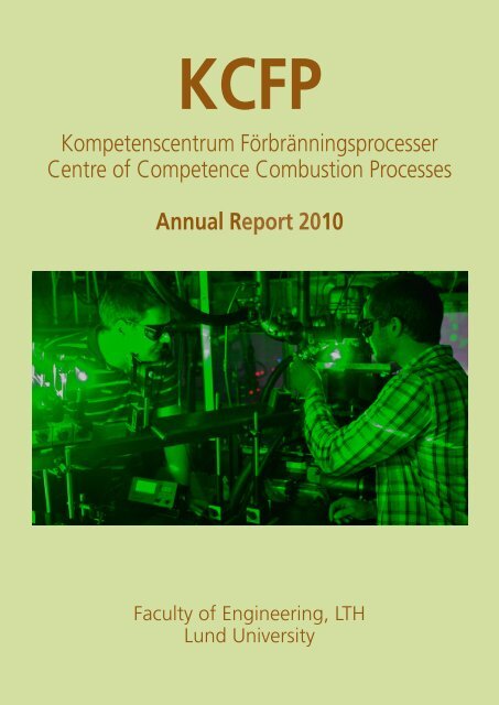
<strong>KCFP</strong><br />
Kompetenscentrum Förbränningsprocesser<br />
Centre of Competence Combustion Processes<br />
<strong>Annual</strong> <strong>Report</strong> 2010<br />
Faculty of Engineering, LTH<br />
Lund University
<strong>KCFP</strong><br />
Centre of Competence Combustion Processes<br />
The Centre of Competence Combustion Processes, <strong>KCFP</strong>, started July 1 1995.<br />
The main goal of this centre is to better understand the combustion process in internal<br />
combustion engines. Of particular interest are the combustion processes with low enough<br />
temperature to suppress formation of NOx and particulates, PM, often called Low Temperature<br />
Combustion, LTC or Homogeneous Charge Compression Ignition, HCCI.<br />
The Centre of Competence Combustion Processes has a budget of 22.25 MSEK per year.<br />
This is roughly one third each from the Swedish Energy Agency, STEM, Lund University and<br />
the Industry.<br />
CONTENTS<br />
1. The Partially Premixed Combustion Project 6<br />
1.1 PPC - Heavy Duty 6<br />
1.2 PPC - Light Duty 10<br />
1.3 Optical Diagnostics 12<br />
1.4 Combustion Modelling 16<br />
1.5 PPC Fuels 18<br />
1.6 Combustion Control 20<br />
2. The Generic Diesel Project 23<br />
2.1 Analysis of the Initial Soot Formation During an EGR Sweep 23<br />
2.2 Post-Injection Effects on Near-Injector Over-Lean Mixtures<br />
and UHC Emissions 24<br />
2.3 Optical Diagnostics Development 26<br />
3. The Gas Engine Project 30<br />
3<br />
INDUSTRY<br />
PARTNERS<br />
Volvo Cars<br />
Volvo Powertrain<br />
Volvo Penta<br />
Saab<br />
Scania<br />
Toyota<br />
Caterpillar<br />
Cargine<br />
Chevron<br />
Finnveden<br />
Hoerbiger<br />
Wärtsilä<br />
The Swedish Gas<br />
Centre, SGC
Associate<br />
Professor<br />
Per Tunestål<br />
Supervisor for:<br />
CC and SIGE<br />
<strong>KCFP</strong><br />
ORGANISATION<br />
BOARD<br />
Sören Udd, Volvo Powertrain<br />
Börje Grandin, Volvo Cars<br />
Annika Kristoffersson, Saab (Chair)<br />
Jonas Hoffstedt, Scania CV<br />
Professor<br />
Marcus Aldén<br />
Supervisor for:<br />
PPC and<br />
GenDies<br />
Associate<br />
Professor<br />
Mattias Richter<br />
Supervisor for:<br />
PPC and<br />
GenDies<br />
Professor<br />
Rolf Johansson<br />
Supervisor for:<br />
CC<br />
DIRECTOR<br />
Professor<br />
Bengt Johansson<br />
Supervisor for:<br />
PPC<br />
Assistant<br />
Professor<br />
Öivind Andersson<br />
Supervisor for:<br />
GenDies<br />
4<br />
Ulla Holst, LTH<br />
Ida Truedsson, LTH<br />
(student representative)<br />
Professor<br />
Xue-Song Bai<br />
Supervisor for:<br />
CM<br />
ADMINISTRATOR<br />
Maj-Lis Roos<br />
Assistant<br />
Professor<br />
Martin Tunér<br />
Supervisor for:<br />
Fuel<br />
ADMINISTRATOR<br />
Elna Andersson
Vittorio Manente<br />
PhD Student<br />
1. The Partially Premixed Combustion Project<br />
Partially Premixed Combustion, PPC, is a combustion process between Homogeneous<br />
Charge Compression Ignition, HCCI and the classical diffusion controlled diesel combustion.<br />
With PPC it is possible to moderate the charge stratification and thus control the<br />
burn rate better than with HCCI. In comparison to classical diesel combustion the NOx and<br />
particulates can be suppressed with orders of magnitude. <strong>KCFP</strong> has five different but linked<br />
subprojects on PPC.<br />
In the Heavy Duty PPC subproject, the first Ph.D. student, Vittorio Manente, has been running<br />
a Scania D13 truck size diesel engine with PPC using diesel fuel as well as gasoline in<br />
the 69-99 octane range. With gasoline it was possible to run from idle up to 30 bar IMEP<br />
even though only 26 bar was reported. Vittorio presented his thesis in September 2010 and<br />
was replaced by Peter Andersson. Peter has been focusing on ethanol as PPC fuel and initial<br />
tests has shown great potential with much less soot. In The Light Duty PPC project, PPC-LD,<br />
the Ph.D. student Patrick Borgqvist has been working with SI and HCCI reference tests in the<br />
low load regime. He has also designed a combustion chamber that should enable PPC combustion<br />
with the active valve train from Cargine. In the PPC-Fuels subproject the student,<br />
Hadeel Solaka, has been working with fuel and combustion interactions with the same fuels<br />
previously used in the PPC-HD project. Larger than expected differences between Heavy<br />
Duty and Light Duty engine geometries were found. The PPC optical diagnostics have been<br />
in a build-up phase with of two kind of activities 2010. A new Scania D13 optical engine design<br />
has been developed and machined but due to delays in the lab, it has not been up and<br />
running during 2010 but will do so 2011. Due to the delay, the optical diagnostics activities<br />
2010 have been performed in stationary test rigs instead. The PPC modelling subproject<br />
is based on the HCCI and SACI models developed in the previous phase of <strong>KCFP</strong>. The PPC<br />
model with LES started with using gaseous jet modelling and will eventually move to include<br />
also sprays. The fundamental DNS simulations of hydrogen spray and combustion can<br />
give additional insight on the PPC type of combustion. The former controls project has due<br />
to budget constraints been reduced in the current phase of <strong>KCFP</strong>, thus less results can also<br />
be expected. Even so, the PPC control project has done mode switch SI-HCCI-SI using model<br />
based control in the PPC-LD engine having the fully flexible valve system. The developed<br />
control strategies can also be useful for PPC.<br />
1.1. PPC - Heavy Duty<br />
Gasoline PPC Combustion in Scania D13 Engine<br />
During 2010 tests with a Scania D13 engine were performed using various types of gasolines<br />
with a range of octane numbers. Figure 1 shows the resulting operating range as a function<br />
of octane number with fixed low inlet temperature. For low ON it is possible to use PPC<br />
mode of combustion from idle to 26 bar IMEP but with a octane number above 70 low load<br />
becomes a problem. With commercial gasoline with RON in the 95-99 range the low limit s<br />
15 bar. How to enable also low load operation will be investigated in the future.<br />
6
Figure 1: Load range with inlet temperature of 25C.<br />
Figure 2: Emissions as a function of load for two low octane gasoline in comparison to future<br />
emission limits in US and Europe.<br />
7
Peter Andersson<br />
PhD Student<br />
Figure 2 shows that the emission levels with low octane gasoline can be below the legal limits<br />
(except for Pm at higher loads). With some fine tuning and optimization also PM could be<br />
within target.<br />
Tests with modified combustion chamber, spray umbrella angle and swirl levels were performed<br />
in order to repeat the 2008-2009 results in the former Scania D12 geometry. Swirl<br />
was increased to 3.7, spray angle set to 120 degrees and a piston with 14.3 nominal compression<br />
ratio was installed. An improvement in soot-NOx trade-off was found with increased<br />
swirl but the combustion chamber shape was found less suitable with the narrow spray angle<br />
of 120 degrees. A new combustion chamber must thus be designed and evaluated during<br />
2011.<br />
Ethanol PPC Results<br />
Figure 3: Combustion chambers and resulting soot-NOx trade-off<br />
with increased swirl level (HS) at loads 50-100% at A speed.<br />
As with the gasoline PPC the whole load range can be optimized for low emissions and relatively<br />
high efficiency with 40-45% of EGR and low λ using ethanol as fuel. The main diffrence<br />
to gasoline is that no soot is formed
Figure 4: Heat release, injection signal and cylinder pressure for low and medium load ethanol PPC.<br />
Figure 5: Combustion efficiency.<br />
Even though a low lambda can be used with ethanol without producing soot a high level of<br />
EGR is needed to slow down the combustion and prevent excessive the pressure rise rate. For<br />
low loads the EGR level has a minor influence while it is of great interest for middle and high<br />
loads.<br />
Planned activities<br />
For 2011, the current campaign with 95% ethanol is to be finished and investigations with<br />
ethanol and λ = 1 is in the pipeline. Further work is to modify the engine with a new combustion<br />
chamber, i.e. a new piston, to investigate how this influence the efficiency.<br />
9
Patrick Borgqvist<br />
PhD Student<br />
1.2 PPC - Light Duty<br />
Introduction<br />
Gasoline partially premixed combustion is a promising way to achieve simultaneous high efficiency<br />
and low soot and NOx emissions in a diesel engine. Running on gasoline, there is<br />
a potential to get adequate premixing of fuel and air to avoid soot formation. With proper<br />
fuel injection strategy, the combustion is controlled so that excessive heat-release rates are<br />
avoided, which is one of the problems with HCCI combustion at higher loads.<br />
The problem with gasoline partially premixed combustion is the limeted operating region<br />
running with higher octane number fuels. See Figure 1. The purpose of this project is to<br />
increase the attainable operating region and increase the understanding of the combustion<br />
process. The approach is to use a variable valve timing system and different fuel injection<br />
strategies. At a later stage, laser diagnostics will be applied to get increased knowledge and<br />
detailed information of the combustion.<br />
During the first year, an extensive pre-study has been carried out. The purpose is to investigate<br />
and compare spark ignited and HCCI combustion with high octane number fuel (RON95)<br />
using variable valve timings within the target area (circled in the diagram).<br />
Figure 6: Experimental engine and piston crown.<br />
Experimental Setup<br />
The research engine is based on a Volvo D5. It has been modified to run on only one of the five<br />
cylinders, and is equipped with a Cargine fully flexible pneumatic variable valve train system,<br />
a spark plug and both a direct injection and port-fuel injection system. At the first stage, only<br />
the port-fuel injection system has been used. The piston crown had to be modified in order to<br />
get valve clearance around top-dead centre. The piston crown design was inspired by a design<br />
in an article from Toyota [1]. The research engine and piston crown can be seen in Figure 6..<br />
10
Figure 7: Collected rate of heat release curves, operating point 1500 rpm, 3.5 bar IMEP net.<br />
Results<br />
The engine was run port-fuel injected with gasoline (RON95) at engine speeds 1500 rpm and<br />
2000 rpm. Spark ignited and HCCI combustion using different variable valve timings strategies<br />
were compared; spark ignited combustion using conventional valve timings and a throttle to<br />
control load (SI Throttle); spark ignited combustion using late intake valve closing timing (SI<br />
LIVC); spark ignited combustion using early intake valve closing (SI EIVC); HCCI combustion using<br />
negative valve overlap (HCCI NVO); HCCI combustion using retarded closing of the exhaust<br />
valve (HCCI Reb 1); HCCI combustion using a second opening of the exhaust valve late during<br />
the intake stroke (HCCI Reb 2); HCCI with conventional valve timings and pre-heated air. Combustion<br />
timings were optimized for maximum indicated efficiency for each strategy.<br />
The collected rate of heat-release curves from operating point 3.5 bar IMEPnet is seen in Figure<br />
7. The apparent difference between spark ignited combustion and HCCI combustion are<br />
clearly seen. With Partially premixed combustion the goal is to achieve a curve which would<br />
be somewhere in between the spark ignited and HCCI curves. This would be obtained with<br />
a more advanced injection strategy. With a controllable combustion, excessive heat-release<br />
rates can be avoided, and high efficiency with acceptable pressure rise rates can be obtained.<br />
11
Figure 8: Net indicated efficiency, operating point 1500 rpm.<br />
The net indicated efficiencies are summarized in Figure 8. The relative improvement in efficiency<br />
is up to approximately 25% comparing the HCCI Rebreathing strategies with the spark<br />
ignited strategies. The HCCI negative valve overlap strategy suffers mainly from lower gasexchange<br />
efficiency and the pre-heated air HCCI strategy suffers from low combustion efficiency.<br />
References<br />
[1] Improvement of Diesel Engine Performance by Variable Valve Train System, T. Tomoda,<br />
T. Ogawa, H. Ohki, T. Kogo, Dr. K. Nakatani, E. Hashimoto, Toyota Motor Corporation, Japan,<br />
30. Internationales Wiener Motorensymposium 2009<br />
1.3 Optical Diagnostics<br />
Further work on multiple scattering suppression for spray imaging<br />
Structured Laser Illumination Planar Imaging, SLIPI, is a planar imaging technique capable of<br />
suppressing multiple scattering. The principle of the technique is to use a laser sheet which<br />
is spatially modulated in intensity instead of a homogeneous laser sheet. This modulation,<br />
which has a sinusoidal pattern, acts as a ”finger print” allowing the singly scattered photons<br />
to be recognized, as they will scatter accordingly. In contrast, photons which are scattered<br />
several times within the sample before detection appear as a position-dependent intensity<br />
noise on the recorded image and will not follow the modulation pattern. To extract the single<br />
scattering from the multiple light scattering intensity, the method consists in extracting the<br />
amplitude of the modulated component. This does, however, require three modulated images<br />
to be recorded for each event.<br />
Imaging of optical depth<br />
The optical depth describes the turbidity of a sample and is usually measured by illuminating<br />
the medium with a laser beam and to measure the reduction of light in the far field. The<br />
undesired detection of multiple scattering makes imaging of optical depth extremely challenging<br />
and the resulting value is often underestimated using conventional imaging methods.<br />
By combining structured illumination with transmission imaging it is possible to visualize the<br />
optical depth in two dimensions while minimizing the influence from multiple scattered light.<br />
Figure 9 shows an example of such a measurement.<br />
12
Figure 9: Two-dimensional measurements of optical dept in a water spray. The image to the left shows<br />
the results obtained with conventional technique and the image to the right is obtained using SLIPI to<br />
suppress multiply scattered light. Note the underestimation that occurs when scattered light taken into<br />
account.<br />
3D imaging with correction for signal losses<br />
Imaging of turbid media, such as sprays, is challenging not only because of multiple scattering<br />
but also because of losses of both the light from the light source as well as the signal itself.<br />
Figure 10 shows a three-dimensional view of an aerated spray corrected for these losses of<br />
light. This was made possible by measuring the optical depth simultaneously imaging the<br />
sample at different positions.<br />
Figure 10: Three-dimensional view of an aerated water spray that has been corrected for the above<br />
mentioned intensity losses.<br />
13
First test of SLIPI in a diesel spray<br />
The first preliminary test of applying the SLIPI technique to a diesel spray has been conducted.<br />
The tests were performed in a spray chamber with an ambient pressure of 19 bar and the injection<br />
pressure was 600 bar. Commercial diesel fuel was used throughout the test. Although<br />
the conditions were not replicating true in-cylinder conditions, the results are promising for<br />
future applications in engines.<br />
Figure 11: Mie scattering at different times after start of injection (TSOI) recorded with conventional<br />
sheet imaging (above) and SLIPI (below). Injection pressure 600 bar, chamber ambient pressure 19 bar.<br />
Note the significant amount of multiple scattered light in the conventional images.<br />
Wall temperature measurements<br />
As outlined in the previous report there is an interest in measuring the in-cylinder wall temperature.<br />
This is especially the case when running combustion systems with high pressure<br />
rise rates such as HCCI and PPC. There is a possibility that the induced pressure oscillations<br />
can rupture the thermal boundary layer and thus cause a severe increase in heat transfer to<br />
the relatively cold wall. Such phenomena could be investigated using thermographic thermometry.<br />
The surface of interest is coated with a thin layer of a suitable thermo sensitive<br />
material often referred to as a thermographic phosphor. Then the coating is illuminated with<br />
laser radiation and shortly thereafter, when the excited phosphor relaxes, light is emitted. This<br />
resulting radiation from most thermographic phosphors has a duration and spectral characteristics<br />
that is dependent on the temperature. Measurements of the signal decay generally<br />
results in a temperature reading with higher precision compared to corresponding spectral<br />
measurements. Decay times are measured using photo multiplier tubes (PMT) which limits<br />
this approach to point temperature measurements. Spectral investigations are often based<br />
on taking the ratio between two recordings performed at two different wavelengths. This can<br />
be performed using high sensitivity cameras which enable two-dimensional measurements.<br />
These techniques have been applied in engines before both within kcfp and at other research<br />
centers. Thermographic phosphors have proven to be a robust technique capable of delivering<br />
qualitative and quantitative data also when applied in harsh environments such as engines.<br />
However, what has been lacking is detailed knowledge about the precision and accuracy of<br />
the measurement technique.<br />
14
The two main approaches (decay time and spectral) are both in need of thorough studies in<br />
order to reach a level where absolute temperatures can be presented with reliable error bars.<br />
The latter is highly important if small temperature variations on an in-cylinder wall should be<br />
possible to detect in a trustful manner. An extensive effort has been focused on refining the<br />
two-dimensional temperature measurement technique in order to bring it to the desired level.<br />
This, still ongoing, study includes detailed investigations on: reproducibility, spectral ratio<br />
dependence of phosphorescence intensity, laser intensity, detector gain, detector integration<br />
time and phosphor layer thickness. All these parameters must be taken into account if real<br />
quantitative data with known measurement errors should be possible. A fundamental, but<br />
far from trivial, requirement is that the spectral intensity ratio should depend on the surface<br />
temperature only. This means that even if the original measurements performed at two different<br />
wavelengths should show intensity variations due to laser intensity variations or variations<br />
in phosphor concentration, the resulting ration between these two images should only<br />
reflect temperature, se example in Figure 12. So far the investigations have revealed a much<br />
greater complexity than initially expected. However, if carried out carefully the thermographic<br />
phosphor technique shows great potential of reaching a measurement precision of only a few<br />
percent also for 2D temperature probing and that is truly outstanding for a probing technique<br />
with such high temporal resolution.<br />
Figure 12: For the ratio method two images (upper two) are detected through different optical filters and then<br />
the ratio is calculated. This resulting ratio image (above) holds the temperature information. In this particular<br />
case it can clearly be seen how variations in the raw data, caused by laser intensity variations, are canceled out<br />
when the ratio is calculated. This is unfortunately not always the case, and if reliable temperature data is to be<br />
retrieved all the above mentioned parameters must be considered.<br />
15
Rickard Solsjö<br />
PhD Student<br />
Tobias Joelsson<br />
PhD Student<br />
1.4 Combustion Modelling<br />
Introduction<br />
The goal of the PPC modelling project is to use high fidelity simulation methods to simulate<br />
to a rather detailed level the spray injection, the gas jet mixing with ambient EGR and air, and<br />
the ignition/reaction fronts propagation in PPC engines. Modeling tools developed in <strong>KCFP</strong><br />
phase 5 and CeCOST 3 are used for the PPC studies. Specially, large eddy simulation (LES) will<br />
be used, instead of Reynolds averaged Navier-Stokes (RANS) modeling, as LES can capture the<br />
most energetic turbulence structures down to the Taylor micro-scales, and only the sub-scale<br />
turbulence transport for mass, momentum and energy needs to be modeled. This way the<br />
most important phenomena in PPC are simulated properly, such as the vortex shedding and<br />
Kelvin-Helmholtz instability associated with the gas jet and the liquid spray injection, the gas<br />
jet flow interaction with piston wall, etc. For the high speed spray injection study an open<br />
source code OpenFoam is used to take into account the compressibility effect. In addition to<br />
the available tools developed previously, particular flow/chemistry coupling models for PPC<br />
ignition and combustion wave propagation needs to be revisited and validated. This involves<br />
study of PPC using direct numerical simulation (DNS). DNS is developed under generic conditions<br />
for simple fuels such as hydrogen. The modeling project is operated in close collaboration<br />
with the engine experiments and laser diagnostics activities within <strong>KCFP</strong>, to gain maximum<br />
synergy effect to improve the understanding of the fundamental physical and chemical<br />
processes involved in PPC, and to be able to explain phenomena found in the engine tests. The<br />
DNS data is used to validate different modeling concepts, e.g. progress variable based ignition<br />
tabulation approach and multi-zone chemistry mapping (MZCM) approach.<br />
Large eddy simulation of high speed gaseous fuel injection<br />
As a first step we investigate the effect of high speed vapor fuel injection on fuel stratification<br />
and fuel-air mixing, at different injection and ambient conditions. To focus the effort, only the<br />
mixing of fuel and air inside a vessel has been considered. The work is conducted using LES<br />
with an open source CFD-software OpenFoam. To achieve improved understanding on the behavior<br />
of the fuel/air mixing, more attention has been placed on the physics at the early stages<br />
of fuel injection. A constant volume enclosure similar to the combustion vessel developed at<br />
Sandia and Lund University has been studied.<br />
(a)(a) (a)(b) (a)(c)<br />
Figure 13: Instantaneous distribution of mass fraction of fuel in the combustion vessel; (a) 1100 bar<br />
injection pressure and ambient density of 22.8kg/m 3 , (b) 2000 bar injection pressure and ambient density<br />
of 22.8kg/m 3 , (c) 2000 bar injection pressure and ambient density of 40kg/m 3 .<br />
16
Figure 13 shows the effect of injection pressure and ambient density on the mixing of fuel<br />
and the ambient air. With lower injection pressure and lower density (case a) the instability of<br />
the jet develops later and mixing of the fuel with ambient is slower; increasing the injection<br />
pressure leads to an earlier onset of Kelvin-Helmholtz instability and enhanced mixing (case<br />
b); increasing density, however, leads to a delay of instability and slower mixing (case c).<br />
Figure 14. Probability density function (PDF) of fuel mass fraction in the vessel; injection pressure<br />
1100 bar, ambient density 22.8kg/m3 .<br />
The mixing field may be characterized using probability density function of fuel mass fraction<br />
in the vessel. For a homogeneous mixture the PDF shows a spike at the given fuel mass fraction<br />
of the mixture. For a very inhomogeneous mixture the PDF shows a wide distribution<br />
over the mass fraction of fuel. As seen in Figure 14, at later times, 2 ms to 5 ms, the fuel distribution<br />
evolves with time to more homogeneous inside the vessel. This can be seen by the<br />
growing peak at mass fraction value of 0.005 on the fuel mass fraction coordinate. The reason<br />
for the high value of the PDF at fuel mass fraction of zero is the large air rich region in the<br />
vessel. The highest value of mass fraction of fuel in the vessel is shown to decrease with time.<br />
At early times, e.g. 0.5 ms, the fuel is still in the early mixing process; there is a wide interval<br />
of different mass fraction values. A systematic parameter investigation for different injection<br />
conditions including multiple injections of fuel is currently undertaken.<br />
Direct numerical simulation of PPC<br />
To improve the understanding of the structures and mechanisms of PPC ignition and reaction<br />
front propagation, DNS is employed to simulate a H2 jet injected into hot air in a constant volume<br />
vessel of 10x10x20 mm3 . The hot air has a temperature of 1000K and pressure of 30 bar.<br />
The fuel is injected through a 1 mm diameter nozzle at 300K and 100 m/s. Figure 15 shows<br />
the auto-ignition process characterized with the H radicals and fuel distribution at 5 consecutive<br />
instants. The first frame from the left shows the start of ignition where the ignition site<br />
is found at the low left side, slightly downstream of the nozzle. At this instant, the fuel jet is<br />
not disturbed by the heat release; the upper half of the jet flow shows a wave shape due to<br />
flow instabilities. After the onset of the ignition, the ignited zone grows quickly outwards to<br />
both upstream and downstream directions. The fuel jet flow is disturbed by the gas expansion<br />
due to heat release. The intensity of H radicals is highest at the propagation fronts indicating<br />
more intense chemical reactions at the fronts; the ignition fronts propagates upwards at a<br />
speed approximately of 400 m/s along the stoichiometric mixture surface surrounding the<br />
fuel jet. Further DNS simulations are being undertaken for conditions with EGR and pressure/<br />
temperature as well as fuels similar to the PPC experiments to be carried out in KC-FP. The<br />
DNS data are currently being analyzed to find correlation between the onset of ignition and<br />
the local flow and mixture properties, and the nature of reaction front propagation. In turn<br />
the results are being used to validate LES models for simulation of flame and ignition under<br />
PPC conditions.<br />
17
Hadeel Solaka<br />
PhD Student<br />
Figure 15: Instantaneous H radicals (color contour, upper row), H2 (color contour, low row) and vorticity<br />
isolines (white lines) in the symmetric plane of the constant volume combustion vessel. Results<br />
are from DNS of H2/air mixture with injection velocity of 100 m/s at 300 K into hot air with 1000K.<br />
1.5 PPC Fuels<br />
Introduction<br />
The traditional gasoline and diesel engine types have totally dominated the market for internal<br />
combustion engines during the last century. The quantification and research on fuels<br />
has during this time revolved around these engine types, creating indexes and understanding<br />
that do not necessarily apply to other combustion principles in engines. Novel combustion<br />
principles such as HCCI and PPC, principles that show potential for high efficiency and low<br />
emissions operation, require new understanding on fuel properties.<br />
Since most studies show that the oil reserves have started to decrease and that CO2 emissions<br />
affect the climate in a negative way while at the same time the need for transportation is increasing,<br />
the development of combustion engines faces three major challenges: Replacement<br />
of traditional fuels- Low emissions operation – Low cost operation. Engine with high efficiency,<br />
such as the PPC engine, are needed to meet these challenges. To fully exploit the potential<br />
of the PPC engine, new understanding of the impact from fuel properties is a key issue.<br />
Research<br />
The Volvo research engine D5 has been converted to single cylinder operation, see Fig.16. It<br />
is equipped with the new version of fuel system, piezoinjector, which replaced by a solenoid<br />
injector. Replacing the new injector with an old version was due to mechanical problems that<br />
occurred while running with gasoline as a fuel. The injector failed after reaching 800bars in<br />
injection pressure. This failure was due to the fuel properties differences between diesel and<br />
gasoline.<br />
18
Figure 16 shows the research engine Volvo D5.<br />
However, some experiments have been made with the piezoinjector in PPC-mode. These experiments<br />
were run with gasoline (70 RON and 66 MON) and diesel MK1. By using fuels with<br />
high octane number in diesel engine it is possible to achieve high efficiency and low emissions.<br />
Previous research has shown that the heat release rate shape is improved by higher resistance<br />
to auto-ignition which leads to higher efficiency.<br />
With the new modification of the fuel system some experiments have been run with gasoline<br />
69 octane number and diesel.<br />
Results<br />
The engine-out specific emissions of NOx and Soot are shown in Figs. 17 and 18, respectively.<br />
The trends in these emissions from both experiments are quite similar: diesel gave higher<br />
engine-out emissions than gasoline. Although not presented here, engine-out UHC and CO<br />
emissions were also measured. The values for NOx and Soot were low but there is a penalty<br />
from this that both UHC and CO were high. The trade off between Soot and NOx can be seen<br />
in figs. 17 and 18.<br />
180<br />
160<br />
140<br />
120<br />
NOx [ppm]<br />
100<br />
80<br />
60<br />
40<br />
20<br />
0<br />
0 5 7,5<br />
SOC [CAD]<br />
19<br />
Nox-Diesel @ 4IMEP[bar]<br />
Nox-Diesel @ 7.2 IMEP[bar]<br />
Nox-Diesel @10.5IMEP[bar]<br />
Figure 17: Engine out emissions of NOx as function of load and start of combustion.
Anders Widd<br />
PhD Student<br />
Patrick Borgqvist<br />
PhD Student<br />
FSN [-]<br />
2,1<br />
2<br />
1,9<br />
1,8<br />
1,7<br />
1,6<br />
1,5<br />
1,4<br />
1,3<br />
1,2<br />
1,1<br />
1<br />
0,9<br />
0,8<br />
0,7<br />
0,6<br />
0,5<br />
0,4<br />
0,3<br />
0,2<br />
0,1<br />
0<br />
0 5<br />
SOC [CAD]<br />
7,5<br />
20<br />
Soot-Diesel @4IMEP[bar]<br />
Soot-Diesel @7.2IMEP[bar]<br />
Soot-Diesel @10.5IMEP[bar]<br />
Soot-Diesel @13.2IMEP[bar]<br />
Soot-Gasoline @4IMEP[bar]<br />
Soot-Gasoline @7.2IMEP[bar]<br />
Soot-Gasoline @10.5IMEP[bar]<br />
Soot-Gasoline @13.2IMEP[bar]<br />
Figure 18: Engine out emissions of Soot as function of load and start of combustion.<br />
Future work<br />
The coming research is focused on completing the current campaign which is comparing gasoline<br />
fuel with different octane numbers and understanding how this is affecting the main<br />
parameters in combustion (e.g. efficiency, Soot, NOx and maximum pressure rise rate). The<br />
plan is to run 3 different engine speeds (1200, 1500 and 1800rpm) and make a load sweep (4,<br />
6 and 8 bar) for each rpm and make another sweep of start of combustion (SOC) for each load<br />
around (0, 5 and 10 CAD). Start of combustion (SOC) is defined as 1 % of heat release.<br />
1.6 Combustion Control<br />
Introduction<br />
To the purpose of fuel efficiency and low emissions, the focus of this project is model-based<br />
control of PPC. Physics-based models are favored due to the improved portability of the resulting<br />
controllers as well as the added insight into the physical process. During the year, an<br />
experimental study on mode switch between SI and HCCI has been completed. The attainable<br />
high octane number gasoline partially premixed operation region is limited. Even with<br />
advanced injection strategies and variable valve actuation, low load operating conditions may<br />
be unattainable. One option is to apply combustion mode switching to and from spark ignited<br />
combustion. Future and ongoing work involves modeling of PPC combustion to enable<br />
optimization-based methods to be used for steady-state and transient operation.<br />
Experimental Apparatus and Control System<br />
The research engine hardware is a modified Volvo D5 passenger car size engine. The engine<br />
is modified to run on only one of the five cylinders and is equipped with a fully flexible pneumatic<br />
variable valve train system.<br />
The valve timings are the most important parameters for mode switch control. The states<br />
of the combustion and engine actuators are continuously updated at different rates by the<br />
LabVIEW based engine control system. The engine control software is executed on a separate<br />
target-PC, which is a dedicated real-time system, PXI-8110, running the LabVIEW real-time<br />
operating system. The user interface is run on a separate Windows host computer. The host<br />
PC communicates with the dedicated real-time PC over TCP/IP. The front panel of the control<br />
system is shown in Figure 19.
Figure 19: LabVIEW engine control system front panel<br />
Mode Switch Between SI and HCCI<br />
During mode switches between SI and HCCI in early experiments, rather large variations in<br />
IMEP were observed. The goal of this investigation was to reduce these variations and obtain<br />
a smooth transition. It was discovered that a substantial amount of fuel was retained in<br />
the intake port during SI operation, which produced large spikes in IMEP when the effective<br />
compression ratio was changed to one suitable for HCCI operation. The switch was therefore<br />
carried out by disabling the fuel injection during one cycle, and performing the change<br />
in valve timings over 3 cycles. Closed-loop control was then activated to obtain the correct<br />
steady-state combustion phasing and load after the switch. Two different control strategies<br />
were investigated: PI and State Feedback control.<br />
Figure 20 shows a mode switch sequence. The fuel injection is deactivated at cycle 0 while the<br />
valve timing changes take effect. When closed-loop control was used, the PI-controllers were<br />
activated at cycle 4 and the state feedback controllers at cycle 3.<br />
Figure 20: Mode switch sequence showing the in-cylinder pressure, valve movements, and fuel injection<br />
21
Two PI-controllers were implemented, one that governed IMEP using the fuel injection duration<br />
as control signal, and one that governed the combustion phasing using the Negative Valve<br />
Overlap (NVO). The controllers were tuned to produce optimized steady-state performance<br />
around the nominal set points of combustion phasing of 6 degrees after top dead center and<br />
an IMEP of 3.5 bar. Figure 21 shows the response following a mode switch around cycle 80.<br />
There are noticeable oscillations in IMEP. These oscillations could likely be reduced by further<br />
tuning of the controllers to this particular mode switch, but the PI approach is inherently limited<br />
since there is no communication between the two controllers.<br />
Figure 21: PI control following a mode switch showing the outputs IMEP and<br />
CA50 (left axes) and the control signals fuel injection duration and NVO (right<br />
axes).<br />
To enable state feedback control, system identification was used to obtain a model with the<br />
fuel injection duration and NVO as inputs and combustion phasing and IMEP as outputs. The<br />
model was of fourth order and produced a VAF (Variance Accounted For) score of around<br />
70-80 for both outputs in cross-validation tests. The controller was combined with a state<br />
estimator and implemented in the LabVIEW-based engine control system. Figure 22 shows the<br />
response following a mode switch around cycle 60. The response is a lot smoother than that<br />
of the PI controllers.<br />
Figure 22: State feedback control following a mode switch showing the outputs<br />
IMEP and CA50 (left axes) and the control signals fuel injection duration<br />
and NVO (right axes).<br />
22
2. The Generic Diesel Project<br />
Due to its relatively high efficiency, the diesel engine is an important power source for road<br />
transport. Its importance can be expected to increase as the demands on fuel efficiency increase.<br />
However, its exhaust emissions of oxides of nitrogen and particulates remain challenging.<br />
One recent focus of the Generic Diesel (GenDies) project has been to clarify the mechanisms<br />
behind trends in soot emissions during a wide sweep in exhaust gas recirculation (EGR). When<br />
diluting the charge with EGR, soot emissions typically increase drastically. At a certain EGRlevel<br />
they decrease again. These trends have been investigated by for the first time applying<br />
time-resolved laser-induced incandescence (LII) in the cylinder of an optical heavy-duty<br />
diesel engine.<br />
Another focus has been sources of unburned hydrocarbons (UHC) in a low-temperature combustion<br />
mode. The closing flank of the injector has been shown to cause drastically increased<br />
air entrainment into the diesel jet. The resulting over-lean mixtures have been suspected to<br />
contribute significantly to the UHC emissions. An experiment was devised to see if this overlean<br />
mixture can be rendered combustible by a small post-injection. This experiment was<br />
performed in collaboration with Dr. Mark Musculus at Sandia National Labs and showed that,<br />
with the right injection strategy, this is indeed feasible.<br />
2.1 Analysis of the Initial Soot Formation During an EGR Sweep<br />
Introduction<br />
During an Exhaust Gas Recirculation (EGR)-sweep, the engine out smoke level is typically<br />
characterized by an initial increase with decreasing O mole fraction, followed by a drastic<br />
2<br />
decrease below a certain O level. In this investigation, a time-resolved analysis of the soot<br />
2<br />
distribution is made, in a reacting jet, during such a sweep in EGR.<br />
Methodology<br />
A Scania D12 heavy duty diesel engine, converted into an optically accessible single cylinder<br />
engine of Bowditch design, was used in this investigation. A Multi-YAG laser system was<br />
utilized to create time-resolved Laser Induced Incandescence (LII). The test matrix consisted<br />
of a sweep in inlet O mole fraction between 9 and 21 %. The engine was operated at 6 bar<br />
2<br />
indicated mean effective pressure (IMEP). The crank angle of 50% completion of the heat<br />
release and was kept constant at 9 CAD After Top Dead Center over the whole test matrix.<br />
Results<br />
As the O fraction was lowered from 21% to 9%, the engine out smoke level increased from<br />
2<br />
zero filtered smoke number (FSN) up to a peak of 2 FSN, occurring between 11 and 12% O , 2<br />
from where it decreased down to zero again at 9% O . 2<br />
Although it only represents a limited portion of the combustion chamber, the illuminated section<br />
of the jet should capture the important trends during the early phases of soot formation.<br />
As the portion of the laser sheet containing LII signal is related to the volume of the soot cloud<br />
in the jet, the growth rate of the area is thus related to the soot forming rate. Figure 23 shows<br />
the initial soot area growth rate as function of O fraction. The area growth rate is evaluated<br />
2<br />
as the slope of a linear curve-fit to the soot areas during the first 5 CAD with LII signal. The<br />
soot area growth rate increases rapidly as the O fraction is decreased from 21% and peaks<br />
2<br />
at 13% O . As the O fraction is decreased further the soot area growth rate decreases again.<br />
2 2<br />
23<br />
Clément Chartier<br />
PhD Student<br />
Ulf Aronsson<br />
PhD Student<br />
Johan Sjöholm<br />
PhD Student<br />
Joakim Rosell<br />
PhD Student
Figure 23: The left graph shows soot area growth rate during the first 5 images with LII-signal from 10%<br />
to 21% O 2 . The Images to the right show the raw signal and the derived soot area at -1 CAD ATDC for<br />
14% O 2 .<br />
Conclusions<br />
The evolution of the in-cylinder soot distribution during an EGR sweep is consistent with and<br />
helps explain the trends in engine-out smoke:<br />
The initial growth rate of the soot area, in the plane of the laser sheet, increases when the O2 mole fraction decreases from 21% to 13% which is an indication of a greater net soot production<br />
with decreasing O . It is reasonable to assume that the increased net soot production is<br />
2<br />
partially associated with reduced soot oxidation at low O fractions, although this cannot be<br />
2<br />
quantified from the present data.<br />
Below 13% O , past the peak in smoke emissions the area growth decreases rapidly which<br />
2<br />
is explained by a decreased soot formation. As before, the oxidation is probably aggravated<br />
under these conditions, but this is less important when a limited amount of soot is formed.<br />
2.2 Post-Injection Effects on Near-Injector Over-Lean Mixtures<br />
and UHC Emissions<br />
Background<br />
Low temperature combustion (LTC) is a concept aimed at reducing NOx and PM from diesel<br />
engines by dilution of the charge with large amounts of cooled EGR. However, drawbacks in<br />
terms of elevated UHC emissions are known for low load LTC conditions.<br />
Previous studies have shown that over leaning of the jet after end of injection, due to enhanced<br />
air entrainment, results in mixtures too lean to ignite in the near-injector region. This<br />
behavior is especially seen at low loads when the ignition dwell, i.e. time between end of<br />
injection and start of combustion, is large.<br />
The potential was investigated of post-injections to locally increase the equivalence ratio and<br />
render the mixtures ignitable, in order to reduce UHC emissions. Combined laser diagnostics<br />
were used for indirect measurements of mixing. Combustion intermediates were used as indicators<br />
of the local stoichiometry. Formaldehyde can be found in regions ranging from fuel<br />
lean to fuel rich but it persists late in the cycle only in fuel lean regions. Furthermore, OH<br />
concentrations are high in near-stoichiometric regions. Third, PAH is known as a soot precursor<br />
and is found in overall fuel rich regions. Using combined OH and 355nm PLIF, the different<br />
combustion intermediates can be imaged and give information about the local stoichiometry.<br />
Formaldehyde and PAH can be extracted from spectral analysis of the 355-PLIF fluorescence<br />
signal, since formaldehyde has a particular spectrum with seven distinct peaks between 385<br />
and 445 nm.<br />
24
Results<br />
It was found that for a single injection, OH radicals are formed in the downstream regions<br />
close to the bowl wall and stagnate in this location late in the cycle as shown in Figure 24.<br />
Formaldehyde, i.e. lean regions, are found after EOI around the injector in the center of the<br />
bowl as seen in Figure 25. No sign of fuel rich regions were observed for this case.<br />
Figure 24: Evolution of the OH-radicals downstream position relatively to the injector<br />
nozzle in the jet axis plane for the single injection compared to both investigated postinjection<br />
strategies.<br />
A post-injection strategy able to reduce measured exhaust UHC emissions was found to be<br />
achievable, though very sensitive to the settings of the post-injection. A case with 20% decrease<br />
in UHC emissions was found and repeatability tests showed good results. The postinjection<br />
for this case was closely spaced after the actual end of main injection, by one CAD.<br />
Rate of injection measurements showed that the momentum of the post injection is very low<br />
compared to the main injection and that the fuel mass delivered in the post only is small (1.8<br />
mg). Pressure wave dynamics in the injector body and common rail system are suspected to<br />
cause this behavior since a one CAD shift in the start of post-injection, without changing the<br />
energizing time, gave a similar momentum as the main injection.<br />
The small post-injection caused a sudden appearance of OH radicals in the upstream part of<br />
the jet by 10 CAD ATDC, see Figure 25. This observation indicates that second stage ignition<br />
was made possible close to the nozzle by the post-injected fuel, which must have raised the<br />
local equivalence ratio towards stoichiometry.<br />
A second case of post-injection was investigated to show the sensitivity of the local enrichment<br />
mechanism to changes in post injection strategy. The post-injection duration was kept<br />
constant but its start was delayed by one CAD. Exhaust measurements showed no influence<br />
of the post on UHC emissions for this case compared to the single injection. Furthermore, no<br />
OH radicals were seen closer to the injector. Instead the same trend as for the single injection<br />
was observed, see Figure 25.<br />
25
Figure 25: Simultaneous OH (green) and 355 PLIF (red) images. The left frame is extracted from a sequence<br />
with the single injection whereas the right one is from the small post injection strategy. The<br />
timings are given relative to TDC and to the main EOI. The formaldehyde correlation bar indicates the<br />
similitude of the 355 PLIF signal to a formaldehyde reference spectrum. The darkest colors in the correlation<br />
bar indicate a low correlation whereas the brightest colors indicate that the LIF signal has a<br />
high probability of being formaldehyde-LIF signal.<br />
The fuel lean regions in the center of the bowl remained lean, correlating with the unchanged<br />
UHC emissions. Rate of injection measurements showed that post-injected fuel mass was nine<br />
times higher than the small post case and the momentum was similar to the main injection.<br />
Conclusions<br />
A comparison of the two post-injection strategies suggests that the momentum is crucial.<br />
The post injection momentum should be low enough for the penetration to remain relatively<br />
short. The post-injected fuel should thereby remain in the near-injector region to enrich the<br />
over-mixed zones. Higher momentum in the post would carry the post-injected fuel too far<br />
downstream. The discovery of the small post-injection strategy leading to exhaust UHC reduction<br />
is the result of a trial and error process on the engine. This strategy can be seen as using<br />
pressure dynamics in the fuel system to achieve such a small post injection. Injector dynamics<br />
is not a controlled variable and the transfer of this particular injection strategy to another<br />
engine might not be straightforward. However, the working principle of the local enrichment<br />
by the post is valid and is the major novelty of this study.<br />
2.3 Optical Diagnostics Development<br />
New Ph.D. student in laser/optical diagnostics<br />
During the fall the Ph.D. student Johan Sjöholm, who has been involved with the Gendies<br />
program for almost five years, went on parental leave. At the same time a new Ph.D. student<br />
was recruited. In late August Joakim Rosell joined the group. He has studied physics at Lund<br />
University. After taking the master exam in Physics he studied pedagogics and thereafter he<br />
has been working as a teacher both in Sweden and abroad. Joakim will be focusing on highspeed<br />
diagnostics, mainly using the unique multi-YAG system, which is very well in line with<br />
the needs of kcfp. Initially Joakim worked along with Johan Sjöholm in order to learn as much<br />
as possible about the highly specialized equipment before Johan went on parental leave. During<br />
the winter Joakim has focused on a feasibility study where the multi-YAG and an OPO-laser<br />
are combined in order to target CO molecules. Joakim’s work includes both setting up the<br />
laser hardware and performing test on CO in a controlled environment. If proven successful,<br />
this approach will be used within in the GenDies program, for detection of partially oxidized<br />
zones, in collaboration with visiting professor Paul Miles from Sandia National Labs.<br />
26
Probing of CO molecules<br />
Carbon monoxide, CO, is not only a major pollutant but can also be used as an indicator of<br />
combustion efficiency, since incomplete oxidation of hydrocarbons result in increased concentration<br />
of CO in the burnt gas region. It would thus be useful if this important species could be<br />
monitored in combustion processes. In the ongoing feasibility study CO is probed by exciting<br />
the molecule from its ground state to the excited state and then observing the fluorescence<br />
that occurs when the molecule relaxes from the excited level to a lower. What is special about<br />
laser induced fluorescence of CO is that it requires two-photon excitation in the UV (230.1<br />
nm). This means that two photons must be absorbed for the excitation to take place. This is<br />
in contrast to conventional laser induced fluorescence where only one photon is needed. The<br />
reason for applying two-photon excitation in this case is that the single-photon transitions in<br />
CO occur at wavelengths so short that the light would suffer from severe absorption when<br />
transmitted in air. There are several issues with two-photon excitation. The most obvious are<br />
the reduced signal strength and quadratic dependence on laser power, which means that high<br />
power is required. A perhaps trivial but not less important task is to investigate how strong<br />
CO-signals the new laser system can generate. Another important issue that needs careful<br />
consideration is the interference from C -molecules. Spectrally CO and C can overlap, i.e. they<br />
2 2<br />
produce fluorescence of the same color. C can be formed naturally during combustion but it<br />
2<br />
can also be formed by photo decomposition of the fuel, i.e. introduced by the laser light. In<br />
order to tell these two species apart it must be possible to distinguish CO-fluorescence from<br />
C -fluorescence. There are strategies for this that are based on careful selection of the spec-<br />
2<br />
tral range where the detection is performed. The drawback of this approach is a significantly<br />
reduced detectability, remember that the CO-signal is generally weak from the beginning and<br />
further filtering worsens this. Quite recently another excitation scheme for CO, where laser<br />
light at 217.5 nm is being employed (instead of 230 nm) was proposed. The amount of presented<br />
work using this alternative scheme is very limited and Joakim Rosell is currently performing<br />
comparisons of the two approaches. The potential advantage with the less applied 217.5 nm<br />
excitation is a reduced interference from C . 2<br />
Figure 26: Spectra from CO molecules after two-photon excitation.<br />
27
Implications of applying LII in engine environments<br />
Laser-Induced Incandescence (LII) has traditionally been considered a straightforward and reliable<br />
optical diagnostic technique for in-cylinder soot measurements. As a result, it is nowadays<br />
even possible to buy turn-key LII measurement systems. During recent years, however,<br />
attention has been drawn to a number of unresolved challenges with LII. Many of these are<br />
especially evident in regions with high soot concentrations typically found in combustion engines.<br />
During the work of performing high-repetition rate measurements with LII in diesel<br />
engines several specific challenges were identified. As a consequence, a substantial part of the<br />
high-speed soot measurement campaign performed within the Gendies program was focused<br />
on identifying and understanding the various issues associated with the application of LII in<br />
engine environments in general and at high-speed in particular. This part of the work resulted<br />
in a dedicated technical paper, on the application of high-speed LII in engines. This paper is<br />
accepted for publication at SAE World Congress in 2011. All the identified issues might not<br />
be possible to overcome but they should nevertheless be known and their potential impact<br />
should be considered when interpreting the results.<br />
In short, the LII signal depends on laser fluence. Ideally it is desired to have a plateau on the<br />
fluence curve (LII-signal vs. laser fluence), i.e. a region where the LII signal is independent on<br />
the laser fluence. This means that variations in laser energy do not influence the measured<br />
soot amount. In practice the shape of the fluence curve is highly dependent on the laser beam<br />
profile. A Gaussian profile will produce a LII-signal that continuously increases with laser fluence<br />
and thus, does not show any plateau region. A perfect top-hat profile will introduce severe<br />
sublimation and hence a weaker signal with increasing fluence. In Figure 27, the fluence<br />
curves are shown for different beam profiles generated by altering the sheet forming optics.<br />
Figure 27: The LII-signal versus laser fluence for different laser beam profiles. The<br />
green curve represents a close to top-hat shaped profile that causes severe sublimation<br />
of the soot particles. The blue curve represents a profile with more spatial<br />
wings, i.e. closer to a Gaussian shape, which generates the desired plateau region<br />
where the LII-signal is independent of the laser fluence.<br />
28
In the initial feasibility study, high-speed LII measurements were made in a laminar ethylene/<br />
air flame to test the characteristic features of high-speed LII in a well defined environment<br />
before approaching the engine. Excessive influence of soot sublimation (damages of the soot<br />
caused by the laser) was observed on the LII signals detected for later pulses in the pulse train<br />
when running with pulse separations relevant for engine conditions, see Figure 28<br />
Figure 28: Normalized LII signal from the second of two laser pulses sent through an atmospheric<br />
flame as a function of pulse separation. The effect of soot sublimation is seen for<br />
separations shorter than 20 ms.<br />
Fortunately, corresponding data from the following in-cylinder measurements does not show<br />
signs of the same behavior, which is believed to be due to high mixing and/or very fast soot<br />
formation/oxidation in the measurement volume. This implies that time-resolved LII is a technique<br />
applicable for qualitatively following the evolution of the soot distribution inside a reacting<br />
diesel jet during a single combustion event.<br />
29
Mehrzad Kaiadi<br />
PhD Student<br />
3. The Gas Engine Project<br />
Introduction<br />
Most heavy-duty engines are diesel operated. Severe emission regulations, high fuel prices,<br />
high technology costs (e.g. catalysts, fuel injection systems) and unsustainably in supplying<br />
fuel are enough reasons to convince engine developers to explore alternative<br />
technologies or fuels. Using natural gas/biogas can be a very good alternative due to the<br />
attractive fuel properties regarding emission reduction and engine operation. Heavy-duty<br />
diesel engines can be easily converted for natural gas operation which is a very cost effective<br />
process for producing gas engines. However, due to the high throttle losses and low<br />
expansion ratio the overall engine efficiency is lower than for the corresponding diesel engines.<br />
Moreover the lower density of natural gas results in lower maximum power level.<br />
The existing project is the fourth phase of the natural gas engine project at Lund University.<br />
The previous results show that the stoichiometric operation is a better choice than lean operation<br />
since by using a 3-way catalyst the emissions level can be kept at very low levels and<br />
differences in efficiency are not significant. Based on the previous results the engine operates<br />
stoichiometric and the project focuses mostly on the problems associated with this type of<br />
operation.<br />
Extending the dilution limit of the engine and developing closed-loop control to operate the<br />
engine at its dilution limit has been the main method to reduce throttle losses. New methods<br />
to determine combustion stability during transients have been developed and used together<br />
with model based control methods. New modifications are also performed on EGR and turbocharging<br />
system of the engine to increase the overall efficiency and extend the maximum<br />
load limit.<br />
Objectives<br />
The main objectives of the project during 2010 have been to identify and apply new hardware/strategies<br />
to improve the overall engine efficiency and also extend the maximum load<br />
level of the engine. A summary of the results achieved during 2010 are presented in this<br />
report.<br />
Experimental Results<br />
Some modifications have been performed on the engine in order to improve the efficiency<br />
and extend the maximum load limit. The main modifications were performed on the pistons,<br />
the turbocharging system and the EGR system.<br />
As already mentioned in last year’s report the major modifications on the pistons are<br />
the shape and compression volume. The new pistons generate very high turbulence<br />
and increase the compression ratio from 10.5 to 12. The results show roughly 40% reduction<br />
in combustion duration and at least 2 percent units improvement in gross indicated<br />
efficiency. The new combustion chambers are called “Quartette” in the figures.<br />
The new piston modification results in some changes of the exhaust gas characteristics<br />
and since the engine is equipped with a turbocharger with wastegate, the changes in exhaust<br />
gas characteristics may have direct influence on the boost pressure. The absolute<br />
boost pressure with Quartette pistons is lower which results in lower maximum BMEP.<br />
30
Higher expansion ratio means that more heat is converted into mechanical work in the cylinder<br />
and less energy in the form of exhaust gas enthalpy is available. According to the manufacturer<br />
the exhaust gas temperature should be lower than 760oC. The lower exhaust gas<br />
temperature obtained with higher compression ratio is beneficial in two ways. First, there is a<br />
higher margin to the highest allowable exhaust gas temperature and second, there is potential<br />
to extend the maximum load limit by replacing the turbocharger with a better matched unit.<br />
A Variable Geometry Turbocharger (VGT) has the ability to change the turbine geometry in<br />
order to obtain the desired boost pressure. VGT offers attractive properties such as high flexibility,<br />
minimal amount of lag and wide operating range. VGT technology is extensively used in<br />
diesel engines; however the use of VGT is very much ignored in gasoline engines due to their<br />
relatively high exhaust temperatures. Ordinary VGT materials and designs cannot withstand<br />
temperatures over 890°C. The exhaust gas temperature of gasoline engines could, however,<br />
reach up to 1000°C, versus 650°C in diesel engines.<br />
Normally natural gas engines use the same combustion technology as gasoline engines due<br />
to similar fuel properties. In heavy-duty applications, since the engine speed does not exceed<br />
2000 RPM, the exhaust gas temperature is not very high. After consulting with the R&D group<br />
at Volvo a VGT was designed and mounted on the engine. The engine is operated at the same<br />
engine speeds with WOT and by altering the geometry of the turbine housing the boost was<br />
increased until either knock occurred or the pumping losses started to increase. To suppress<br />
knock, EGR was added and the ignition timing was adjusted accordingly. Figure 29 shows the<br />
boost pressure achieved by the VGT in comparison with the by-pass turbocharger with original<br />
and Quartette pistons. The boost pressure was increased up to much higher levels with<br />
VGT without sacrificing gas-exchange efficiency. The increase in boost pressure resulted in<br />
increased maximum load as presented in Figure 30 compared to previous configurations. The<br />
peak load increased by 18 percent from 16 to 19 bar BMEP.<br />
Figure 29 Boost pressure achieved after replacing the turbocharger with a VGT<br />
31
Figure 30 Maximum load achieved after replacing the turbocharger with a<br />
VGT<br />
Using a throttle always leads to pumping losses. Normally a throttle is used to control the desired<br />
torque in the engines, but it is also possible to use a VGT instead of the throttle in a large<br />
operating range to control the desired torque. This is possible due to the flexibility of the VGT<br />
to adjust the inlet pressure by altering the geometry of the turbine housing. In this operation<br />
region the throttle is kept fully open and the VGT is used to adjust the inlet pressure and finally<br />
control the demanded torque. This means that the throttle will not be used in a large part of<br />
the operating region (roughly 60% of the entire operating area of the engine) and no throttle<br />
use means no throttle losses. The results have been validated in a large operating region and<br />
showed that at least 2 percent units improvement in gas-exchange efficiency is gained. The<br />
dynamics of VGT was also comparable to the throttle dynamics. An innovative driving strategy<br />
with lowest possible throttle losses has been suggested. In summary the key features to<br />
improve the natural gas engine performance are identified as: Right amount of EGR at different<br />
operating regions, Right compression ratio, Variable Geometry Turbocharger (VGT), High<br />
turbulence pistons, Long route EGR system and model-based control.<br />
Planned Activities<br />
Mehrzad Kaiadi will defend his doctoral thesis 2011-02-11. After that the project will focus on<br />
dual fuel operation using direct injection of Diesel fuel for ignition.<br />
32
<strong>KCFP</strong><br />
Kompetenscentrum Förbränningsprocesser<br />
Centre of Competence Combustion Processes<br />
Faculty of Engineering, LTH<br />
P.O. Box 118<br />
SE-221 00 Lund<br />
Sweden