200510095 93-2144 RV Inverter-Charger Owner's Manual - Tripp Lite
200510095 93-2144 RV Inverter-Charger Owner's Manual - Tripp Lite
200510095 93-2144 RV Inverter-Charger Owner's Manual - Tripp Lite

Create successful ePaper yourself
Turn your PDF publications into a flip-book with our unique Google optimized e-Paper software.
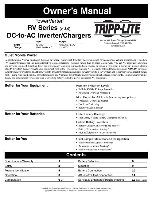
Owner’s <strong>Manual</strong>PowerVerter ®<strong>RV</strong> Series (v. 3.0)DC-to-AC <strong>Inverter</strong>/<strong>Charger</strong>sInputOutputInvert: 12 VDC 120V, 60 Hz. ACCharge: 120V, 60 Hz. AC 12 VDC1111 W. 35th Street, Chicago, IL 60609 USACustomer Support: (773) 869-1234www.tripplite.comQuiet Mobile PowerCongratulations! You’ve purchased the most advanced, feature-rich <strong>Inverter</strong>/<strong>Charger</strong> designed for recreational vehicle applications. <strong>Tripp</strong> <strong>Lite</strong><strong>RV</strong> <strong>Inverter</strong>/<strong>Charger</strong>s are the quiet alternative to gas generators—with no fumes, fuel or noise to deal with! You get AC electricity anywhereand anytime you need it: rolling down the highway, dry camping in majestic back country or parked overnight at a money-saving non-electricsite. <strong>RV</strong> <strong>Inverter</strong>/<strong>Charger</strong>s provide your equipment with utility- or generator-supplied AC electricity (filtered through premium ISOBAR ® surge protection)whenever available. In addition, your <strong>RV</strong> <strong>Inverter</strong>/<strong>Charger</strong> automatically powers your <strong>RV</strong>’s 12V system and recharges your connected batterybank—doing what traditional <strong>RV</strong> converter/chargers do. Whenever power blackouts, brownouts or high voltages occur, your <strong>RV</strong> <strong>Inverter</strong>/<strong>Charger</strong> immediatelyand automatically switches over to inverting battery output to power connected AC equipment.Better for Your EquipmentBetter for Your BatteriesBetter for YouSpecifications/Warranty 2Safety 3Feature Identification 4Operation 5Premium Protection Levels• Built-In ISOBAR ® Surge Protection• Automatic Overload ProtectionIdeal Output for All Loads (including computers)• Frequency-Controlled Output• Fast Load Switching• Balanced Load Sharing*Faster Battery Recharge• High-Amp, 3-Stage Battery <strong>Charger</strong> (adjustable)Critical Battery Protection• Battery Charge Conserver (Load Sense)*• Battery Temperature Sensing*• High-Efficiency DC-to-AC InversionQuiet, Simple, Maintenance-Free Operation• Multi-Function Lights & Switches• Automatic Generator Starting*• Moisture-Resistant Construction †ContentsBattery Selection 8Mounting 9Battery Connection 10AC Input/Output Connection 11Configuration 6-7Service/Maintenance/Troubleshooting12 (back page)* Available on all models except 612 models. †<strong>Inverter</strong>/<strong>Charger</strong>s are moisture-resistant, not waterproof.Copyright © 2003. PowerVerter ® is a registered trademark of <strong>Tripp</strong> <strong>Lite</strong>. All rights reserved.
SpecificationsMODEL NUMBER: <strong>RV</strong>612UL <strong>RV</strong>612ULH <strong>RV</strong>1012UL <strong>RV</strong>1012ULH <strong>RV</strong>1512 <strong>RV</strong>1512OEM <strong>RV</strong>2012OEM <strong>RV</strong>2012UL <strong>RV</strong>2512OEM <strong>RV</strong>3012OEMSeries Number: AGAP60012MVJ AGAP60012MVJ AGAP100012MV3 AGAP100012MV3 AGAP200012MV3 AGAP200012MVP3 AGAP200012MVP3 AGAP200012MV3AC Input Connection: Input Cord Hardwire Input Cord Hardwire Hardwire Hardwire Hardwire Hardwire Hardwire HardwireINVERTERCommon Specifications for All Models: • DC Input Volts (Nominal): 12 VDC • · DC Input Voltage Range: 10 - 15 VDC • Output Volts (Nominal): 120 VAC, ± 5% • Output Frequency (Nominal): 60 Hz, ± 0.5% • Efficiency: 88% to 94%, depending on load and temperatureSelect <strong>Tripp</strong> <strong>Lite</strong> <strong>Inverter</strong>/<strong>Charger</strong>s include a Battery Charge Conserver (Load Sense) Control which saves battery power by allowing users to set the minimum load level at which the unit’sinverter turns on. Users can significantly reduce the No Load DC Input Current (approximately 2.5 to 4 A for all models) to a very low amp level with the use of this control.Continuous Power (@ 20 C): 600 600 1000 1000 1500 1500 2000 2000 2500 3000OverPower Peak Surge Power:* 900 900 1500 1500 2250 2250 3000 3000 3750 4500Double Boost Peak Surge Power:* 1200 1200 2000 2000 3000 3000 4000 4000 5000 6000Maximum Output AC Current 5 A 5 A 8.3 A 8.3 A 12.5 A 12.5 A 16.7 A 16.7 A 20 A 25 A(Continuous):UL Required DC Fuse TPN-80 (fuse) TPN-80 (fuse) ANL-200 (fuse) ANL-200 (fuse) ANL-275 two ANL-200 (fuses) two ANL-200 (fuses) ANL-325 (fuse) two ANL-200 (fuses) two ANL-275 (fuses)and Fuse Block: R25100-1CR (fuse block) R25100-1CR (fuse block) 1DK98 (fuse block) 1DK98 (fuse block) 1DK98 (fuse block) two 1DK98 (fuse blocks) two 1DK98 (fuse blocks) 1DK98 (fuse block) two 1DK98 (fuse blocks) two 1DK98 (fuse blocks)Bussmann Bussmann Bussmann Busmann Bussmann Bussmann Bussmann Bussmann Bussmann Bussmann(manufacturer) (manufacturer) (manufacturer) (manufacturer) (manufacturer) (manufacturer) (manufacturer) (manufacturer) (manufacturer) (manufacturer)DC Input Current @Nominal V DC Full Load: 56A 56A 95A 95A 143 A 143 A 192A 190A 240 A 290ABATTERY CHARGERCommon Specifications for All Models • Acceptance Volts VDC: Selectable 14.4 V** / 14.2 V Wet** / Gel • Float Volts DC (w/gel): 13.3 V (13.6 V) • · Input Volts (Nominal): 120 VACCharging Capacity DC: 45 A / 11 A** 45 A / 11 A** 55 A / 14 A** 55 A / 14 A** 80 A / 20 A** 80 A / 20 A** 100 A / 25 A** 100 A / 25 A** 120 A / 30 A** 140 A / 35 A**Input Current AC: 9.5 A 9.5 A 11.5 A 11.5 A 16.7 A 16.7 A 20 A 20 A 24 A 30 ALINE VAC OPERATIONCommon Specifications for All Models • Input Frequency (Nominal): 60 Hz, ±10% • Maximum Input Volts (Transfer to Battery) (Continuous, <strong>Charger</strong> at Maximum): Selectable 135** or 145 VACMinimum Input Volts: Selectable 95** or Selectable 95** or Selectable 75**, 85, Selectable 75**, 85, Selectable 75**, 85, Selectable 75**, 85, Selectable 75**, 85, Selectable 75**, 85, Selectable 75**, 85, Selectable 75**, 85,(Transfer to Battery) 105 VAC 105 VAC 95 or 105 VAC 95 or 105 VAC 95 or 105 VAC 95 or 105 VAC 95 or 105 VAC 95 or 105 VAC 95 or 105 VAC 95 or 105 VACMaximum Input AC Current 11.3 A 14.5 A 12.1 A 20 A 29 A 29 A 38 A 38 A 44 A 56 A(Continuous, <strong>Charger</strong>at Maximum):Maximum Bypass AC Current: 6 A 6A 12 A 12 A 20 A 15/20 A 15/20 A 20 A 20/20 A 20/20 A(Load circuit breaker limited)* OverPower duration (up to 1 hour). DoubleBoost duration (up to 10 seconds). Actual duration depends on battery age, battery charge level and ambient temperature. **Factory setting. The policy of <strong>Tripp</strong> <strong>Lite</strong> is one of continuous improvement. Specifications are subject to change without notice.Minimum Recommended Cable Sizing Chart †Use in conjunction with DC wiring connection instructions in the Battery Connection section.<strong>Inverter</strong>/<strong>Charger</strong> DC Volt: 12Wire GaugeTwin 00 (2/0)Watts 6 4 2 0 00 (2/0) (<strong>RV</strong>2012OEM, <strong>RV</strong>2512OEM & <strong>RV</strong>3012OEM only)500 15 ft 25 ft 39 ft 62 ft 79 ft 158 ft.700 11 ft 18 ft 28 ft 44 ft 56 ft 112 ft.1000 N/R 12 ft 20 ft 31 ft 39 ft 78 ft.2000 N/R N/R N/R 16 ft 20 ft 40 ft.2400 N/R N/R N/R 13 ft 16 ft 32 ft.3000 N/R N/R N/R 10 ft 13 ft 26 ft.† N/R = Not Recommended. NOTE: Acceptable power is directly related to cable length (i.e. - the shorter the cable, the better the performance)Note on Labeling Two symbols are used on the <strong>RV</strong> labels.V~: AC Voltage : DC VoltageLimited Warranty<strong>Tripp</strong> <strong>Lite</strong> warrants its <strong>Inverter</strong>/<strong>Charger</strong>s to be free from defects in materials and workmanship for a 30 month period from the date of retail purchase by end user.<strong>Tripp</strong> <strong>Lite</strong>’s obligation under this warranty is limited to repairing or replacing (at its sole option) any such defective products. To obtain service under this warranty you must obtain a Returned Material Authorization (RMA) number from <strong>Tripp</strong> <strong>Lite</strong> or an authorized <strong>Tripp</strong> <strong>Lite</strong> service center. Products must be returned to <strong>Tripp</strong> <strong>Lite</strong> or an authorized<strong>Tripp</strong> <strong>Lite</strong> service center with transportation charges prepaid and must be accompanied by a brief description of the problem encountered and proof of date and place of purchase. This warranty does not apply to equipment which has been damaged by accident, negligence or misapplication or has been altered or modifiedin any way, including opening of the unit’s casing for any reason. This warranty applies only to the original purchaser who must have properly registered the product within 10 days of retail purchase.EXCEPT AS PROVIDED HEREIN, TRIPP LITE MAKES NO WARRANTIES, EXPRESS OR IMPLIED, INCLUDING WARRANTIES OF MERCHANTABILITY AND FITNESS FOR A PARTICULAR PURPOSE. Some states do not permit limitation or exclusion of implied warranties; therefore, the aforesaid limitation(s) or exclusion(s)may not apply to the purchaser.EXCEPT AS PROVIDED ABOVE, IN NO EVENT WILL TRIPP LITE BE LIABLE FOR DIRECT, INDIRECT, SPECIAL, INCIDENTAL OR CONSEQUENTIAL DAMAGES ARISING OUT OF THE USE OF THIS PRODUCT, EVEN IF ADVISED OF THE POSSIBILITY OF SUCH DAMAGE. Specifically, <strong>Tripp</strong> <strong>Lite</strong> is not liable for anycosts, such as lost profits or revenue, loss of equipment, loss of use of equipment, loss of software, loss of data, costs of substitutes, claims by third parties, or otherwise.<strong>Tripp</strong> <strong>Lite</strong> has a policy of continuous improvement. Specifications are subject to change without notice.2R
Important Safety InstructionsSAVE THESE INSTRUCTIONS!This manual contains important instructions and warnings that should be followed during the installation, operation and storage of all <strong>Tripp</strong> <strong>Lite</strong><strong>Inverter</strong>/<strong>Charger</strong>s.Location Warnings• Install your <strong>Inverter</strong>/<strong>Charger</strong> (whether for a mobile or stationary application) in a location or compartment that minimizes exposure toheat, dust, direct sunlight and moisture.• Although your <strong>Inverter</strong>/<strong>Charger</strong> is moisture resistant, it is NOT waterproof. Flooding the unit with water will cause it to short circuitand could cause personal injury due to electric shock. Never immerse the unit, and avoid any area where standing water mightaccumulate. Mounting should be in the driest location available.• Leave a minimum of 2" clearance at front and back of the <strong>Inverter</strong>/<strong>Charger</strong> for proper ventilation. To avoid automatic <strong>Inverter</strong>/<strong>Charger</strong>shutdown due to overtemperature, any compartment that contains the <strong>Inverter</strong>/<strong>Charger</strong> must be properly ventilated with adequateoutside air flow. The heavier the load of connected equipment, the more heat will be generated by the unit.• Do not install the <strong>Inverter</strong>/<strong>Charger</strong> directly near magnetic storage media, as this may result in data corruption.• Do not install near flammable materials, fuel or chemicals.Battery Connection Warnings• The <strong>Inverter</strong>/<strong>Charger</strong> will not operate (with or without utility power) until batteries are connected.• Multiple battery systems must be comprised of batteries of identical voltage, age, amp-hour capacity and type.• Because explosive hydrogen gas can accumulate near batteries if they are not kept well ventilated, your batteries should not beinstalled (whether for a mobile or stationary application) in a “dead air” compartment. Ideally, any compartment would have someventilation to outside air.• Sparks may result during final battery connection. Always observe proper polarity as batteries are connected.• Do not allow objects to contact the two DC input terminals. Do not short or bridge these terminals together. Serious personal injuryor property damage could result.Equipment Connection WarningsDo not use a <strong>Tripp</strong> <strong>Lite</strong> <strong>RV</strong> <strong>Inverter</strong>/<strong>Charger</strong> in life support or healthcare applications where a malfunction or failure of a<strong>Tripp</strong> <strong>Lite</strong> <strong>RV</strong> <strong>Inverter</strong>/<strong>Charger</strong> could cause failure of, or significantly alter the performance of, a life support device ormedical equipment.• Corded models: Do not modify the <strong>Inverter</strong>/<strong>Charger</strong>’s plug or receptacle in a way that eliminates its ground connection. Do not usepower adapters that will eliminate the plug’s ground connection.• Connect your <strong>Inverter</strong>/<strong>Charger</strong> only to a properly grounded AC power outlet or hardwired source. Do not plug the unit into itself; thiswill damage the device and void your warranty.• You may experience uneven performance results if you connect a surge suppressor, line conditioner or UPS system to the output ofthe <strong>Inverter</strong>/<strong>Charger</strong>.Operation Warnings• Your <strong>Inverter</strong>/<strong>Charger</strong> does not require routine maintenance. Do not open the device for any reason. There are no user serviceable partsinside.• Potentially lethal voltages exist within the <strong>Inverter</strong>/<strong>Charger</strong> as long as the battery supply and/or AC input are connected. During anyservice work, the battery supply and AC input connection (if any) should therefore be disconnected.• Do not connect or disconnect batteries while the <strong>Inverter</strong>/<strong>Charger</strong> is operating in either inverting or charging mode. Operating ModeSwitch should be in the OFF position. Dangerous arcing may result.3R
ConfigurationSet Configuration DIP SwitchesUsing a small tool, set the Configuration DIP Switches (located on the front panel, see diagram) to optimize <strong>Inverter</strong>/<strong>Charger</strong> operationdepending on your application. <strong>RV</strong>612UL and <strong>RV</strong>612ULH models include one set of four DIP Switches. All other models include an additional setof four DIP switches to configure additional operational functions. Refer to the appropriate section to review the instructions for yourspecific model.B4 B3 B2 B1 A4 A3 A2 A1INPUT C/B 10AOUTPUT C/B 12AGroup B Dip Switches (Not on 612 Models)Group A Dip Switches (All Models)Group A DIP Switches (All Models)Using a small tool, configure your <strong>Inverter</strong>/<strong>Charger</strong> by setting the four Group A DIP Switches (located on the front panel of your unit; seediagram) as follows:A1Select Battery Type—REQUIRED(All models)CAUTION: The Battery Type DIP Switch setting mustmatch the type of batteries you connect, or your batteriesmay be degraded or damaged over an extended period oftime. See “Battery Selection,” p. 8 for more information.Battery TypeGel Cell (Sealed) BatteryWet Cell (Vented) BatteryA4 A3A2A1Switch PositionUpDown (factory setting)A2Select High AC Input Voltage Pointfor Switching to Battery—OPTIONAL*(All Models)Voltage145V135VA4 A3A2A1Switch PositionUpDown (factory setting)All Models Except 612 ModelsA4A3Voltage105V95V85V75VSelect Low AC Input Voltage Pointfor Switching to Battery—OPTIONAL*SwitchPosition#A4 Up & #A3 Up#A4 Up & #A3 Down#A4 Down & #A3 Up#A4 Down & #A3 Down(factory setting)A4 A3 A2 A1A4 A3 A2 A1A4 A3 A2 A1A4 A3 A2 A1612 Models OnlyA4 & A3 SettingsA4 A3 A2 A1A3 Select Low AC Input Point for Switchingto Battery—OPTIONALVoltage Switch Position105VUp95VDown (factory setting)A4 Set Battery Charging Amps Type—High Charge AmpOPTIONALA4 A3 A2 A1Check specifications on for your unit’s high- andlow-charging amp options. By setting on highLow Charge Ampcharging, your batteries will charge at maximumspeed and your <strong>RV</strong> 12V DC system loads will be well-supplied. When setting onlow charging, you lengthen the life of your batteries (especially smaller ones).Battery <strong>Charger</strong> Switch PositionHigh Charge Amp UpLow Charge AmpDown (factory setting)* Most of your connected appliances and equipment will perform adequately when your <strong>Inverter</strong>/<strong>Charger</strong>’s High AC Input Voltage Point (DIP Switch #2 of Group A) is set to 135V and its Low AC Voltage Input Point (DIP Switches #3 and #4 of Group A or DIP Switch #3 for612 models) are set to 95V. However, if the unit frequently switches to battery power due to momentary high/low line voltage swings that would have little effect on equipment operation, you may wish to adjust these settings. By increasing the High AC Voltage Point and/ordecreasing the Low AC Voltage Point, you will reduce the number of times your unit switches to battery due to voltage swings.Group B DIP Switches (Not on 612 Models)B1 B2 Select Load Sharing—OPTIONAL (Not on 612 Models)Your <strong>Inverter</strong>/<strong>Charger</strong> features a high-output battery charger that can draw a significant amount of AC power from your utility source orgenerator when charging at its maximum rate. If your unit is supplying its full AC power rating to its connected heavy electrical loads at thesame time as this high charging occurs, the AC input circuit breaker could trip, resulting in the complete shut off of pass-through utility power.To reduce the chance of tripping this breaker, all <strong>RV</strong> <strong>Inverter</strong>/<strong>Charger</strong>s (except models <strong>RV</strong>612UL and <strong>RV</strong>612ULH) may be set to automatically limitthe charger output. This keeps the sum of the unit’s AC load and charge power within the circuit breaker rating. This charger-limiting functionhas four settings, allowing you to reduce the charger’s draw lower and lower, as needed, if the AC input circuit breaker keeps trippingunder the normal AC loads of devices you have connected downline from the unit. The figures on the next page show how to set your DIPSwitches to determine how heavy the connected load can be on your <strong>Inverter</strong>/<strong>Charger</strong> before charger-limiting begins.6R
Configuration (continued)Select Battery <strong>Charger</strong>-Limiting Points—OPTIONAL(Not on 612 Models)Most Limiting (#B1 & #B2 Up, factory setting):B4 B3 B2 B1<strong>Charger</strong>-limiting takes effect the momentany 120V AC load is applied; charger outputfalls gradually from full output at no 120Vload passing through to no output at full load.Less Limiting (#B1 Down & #B2 Up):B4 B3 B2 B1<strong>Charger</strong>-limiting begins when the<strong>Inverter</strong>/<strong>Charger</strong>’s load reaches 33% of the<strong>Inverter</strong>/<strong>Charger</strong>’s load rating. <strong>Charger</strong>output falls gradually from full output at 33% of the<strong>Inverter</strong>/<strong>Charger</strong>’s load rating to about 40% of full output at full load.B3 Select Equalize Battery Charge—OPTIONAL(Not on 612 Models)This DIP Switch is momentarily engagedto begin the process of equalizing thecharge state of your battery’s cells by timelimitedovercharge of all cells. This canB4 B3 B2 B1 ResetEqualizeextend the useful life of certain types of batteries; consult with yourbattery’s manufacturer to determine if your batteries could benefitfrom this process. The charge equalization process is automatic;once started, it can only be stopped by removing the input power.Least Limiting (#B1 Up & #B2 Down):<strong>Charger</strong>-limiting begins when the<strong>Inverter</strong>/<strong>Charger</strong>’s load reaches 66% of the<strong>Inverter</strong>/<strong>Charger</strong>’s load rating. <strong>Charger</strong>output falls gradually from full output atB4 B3 B2 B166% of the <strong>Inverter</strong>/<strong>Charger</strong>’s load rating to about 40% of full outputat full load.No Limiting (#B1 & #B2 Down): Nocharger-limiting occurs at any load size.Setting Procedure• Move to “Equalize” (DOWN) position for three seconds.• Move to “Reset” (UP) position and leave it there. This is thefactory default setting.CAUTION: Do not leave DIP switch #B3 in the down position after beginning process. Batterycharge equalization should only be performed in strict accordance with the battery manufacturer’sinstructions and specifications.Battery ChargeResetEqualizeB4B3Switch PositionUp (factory setting)Down—momentarilyB2B1B4 Set Battery Charging Amps—OPTIONAL (function includedon A4 switch on 612 models)Check specifications for your unit’s high- andlow-charging amp options. By setting onhigh charging, your batteries will charge atmaximum speed and your <strong>RV</strong> 12V DCsystem loads will be well-supplied. WhenB4 B3 B2 B1setting on low charging, you lengthen the life of your batteries(especially smaller ones).7RBattery <strong>Charger</strong>Low Charge AmpsHigh Charge AmpsSwitch PositionUpDown (factory setting)CAUTION: When switching to the High Charge Amp setting, the user must ensure that the amphour capacity of their battery system exceeds the amperage of the High Charge Amp setting orthe batteries may be damaged or degraded.Set Battery Charge Conserver (Load Sense) Dial—OPTIONAL (Not on 612 models)In order to save battery power, the unit’s inverter automatically shuts off in the absence of any power demand from connectedequipment or appliances (the electrical load). When the unit detects a load, it automatically turns its inverter function on.Users may choose the minimum load the <strong>Inverter</strong>/<strong>Charger</strong> will detect by adjusting the Battery Charge Conserver Dial (seediagram). Using a small tool, turn the dial clockwise to lower the minimum load that will be detected, causing the inverter toturn on for smaller loads. When the dial is turned fully clockwise, the inverter will operate even when there is no load. Turn the dial counterclockwiseto increase the minimum load that will be detected, causing the inverter to stay off until the new minimum load is reached.Note: the factory setting for the dial is fully clockwise. However, based on the threshold load to which you’d like the inverter to respond, you should adjust the dial counterclockwise to reduce its sensitivityuntil the inverter is active only when connected equipment or appliances are actually in use.Connect Remote Control—OPTIONAL (All models)All models feature an 8-conductor telephone style receptacle on the front panel for use with an optional remote control module (<strong>Tripp</strong> <strong>Lite</strong> modelAPSRM2, sold separately or included with select models). The remote module allows the <strong>Inverter</strong>/<strong>Charger</strong> to be mounted in a compartment or cabinet outof sight, while operated conveniently from within the living area or control panel of your <strong>RV</strong>. See instructions packed with the remote control module.Connect Battery Temperature Sensing Cable—OPTIONAL (not on 612 models)The battery temperature sensing function prolongs battery life by adjusting the charge float voltage level based on battery temperature. Connectthe sensor cable (the cable, included with select models, has an RJ style connector on one end and a black sensor on the other) to the RJstyle jack located on the side of the <strong>Inverter</strong>/<strong>Charger</strong> labeled “Remote Temp. Sense.” Affix the sensor to the side of your battery below theelectrolyte level. To guard against false readings due to ambient temperature, place the sensor between batteries, if possible, or away fromsources of extreme heat or cold. If the sensor cable is not used, the <strong>Inverter</strong>/<strong>Charger</strong> will charge according to its default 25º C values.Utilize Automatic Generator Starter Capability—OPTIONAL (not on 612 models))All models except 612 models include an RJ type modular jack on the side panel labeled “Generator Start”. Attach to vehiclegenerator ON/OFF switching mechanism with user-supplied cable (see Pin Configuration Diagram). Onceattached, the interface will allow the <strong>Inverter</strong>/<strong>Charger</strong> to automatically switch a vehicle generator on when connected batteryvoltage levels are low (11.6 VDC) and switch it off when battery voltage levels are high (14.1 VDC).135246Pin Configuration2 - Common3 - N.C.(Normally Closed)4 - N.O.(Normally Open)
Battery SelectionSelect Auxiliary Battery Type (if any)Select “Deep Cycle” batteries to receive optimum performance from your <strong>Inverter</strong>/<strong>Charger</strong>. Do not use ordinary car or starting batteries or batteriesrated in Cold Cranking Amps (CCA). If the batteries you connect to the <strong>Inverter</strong>/<strong>Charger</strong> are not true Deep Cycle batteries, their operational lifetimesmay be significantly shortened. If you are using the same battery bank to power the <strong>Inverter</strong>/<strong>Charger</strong> as well as DC loads, your battery bankwill need to be appropriately sized (larger loads will require a battery bank with a larger amp-hour capacity) or the operational lifetimes of the batteriesmay be significantly shortened.Batteries of either Wet-Cell (vented) or Gel-Cell /Absorbed Glass Mat (sealed) construction are ideal. 6-volt “golf cart”, Marine Deep-Cycleor 8D Deep-Cycle batteries are also acceptable. You must set the <strong>Inverter</strong>/<strong>Charger</strong>’s Battery Type DIP Switch (see Configuration sectionon page 6 for more information) to match the type of batteries you connect or your batteries may be degraded or damaged over an extendedperiod of time. In many cases, the vehicle battery may be the only one installed. Auxiliary batteries must be identical to the vehicle batteriesif they are connected to each other.Match Battery Amp-Hour Capacity to Your ApplicationSelect a battery or system of batteries that will provide your <strong>Inverter</strong>/<strong>Charger</strong> with proper DC voltage and an adequate amp-hour capacity topower your application. Even though <strong>Tripp</strong> <strong>Lite</strong> <strong>Inverter</strong>/<strong>Charger</strong>s are highly-efficient at DC-to-AC inversion, their rated output capacities arelimited by the total amp-hour capacity of connected batteries and the support of your vehicle’s alternator if the engine is kept running.ExampleTools• STEP 1: Determine Total Wattage Required¼" Drill Orbital Sander Cordless Tool <strong>Charger</strong>Add the wattage ratings of all equipment you will connect to your <strong>Inverter</strong>/<strong>Charger</strong>.Wattage ratings are usually listed in equipment manuals or on nameplates. If yourequipment is rated in amps, multiply that number times AC utility voltage to determinewatts. (Example: a ¼ in. drill requires 2½ amps. 2½ amps × 120 volts = 300 watts .)Note: Your <strong>Inverter</strong>/<strong>Charger</strong> will operate at higher efficiencies at about 75% - 80% of nameplate rating.300W + 220W + 20W = 540WAppliancesBlender Color TV Laptop Computer300W + 140W + 100W = 540W• STEP 2: Determine DC Battery Amps RequiredDivide the total wattage required (from step 1, above) by the battery voltage (12)to determine the DC amps required.• STEP 3: Estimate Battery Amp-Hours Required (for operation unsupportedby the alternator)Multiply the DC amps required (from step 2, above) by the number of hours youestimate you will operate your equipment exclusively from battery powerbefore you have to recharge your batteries with utility- or generator-suppliedAC power. Compensate for inefficiency by multiplying this number by 1.2.This will give you a rough estimate of how many amp-hours of battery power(from one or several batteries) you should connect to your <strong>Inverter</strong>/<strong>Charger</strong>.NOTE! Battery amp-hour ratings are usually given for a 20-hour discharge rate. Actual amp-hour capacities are lesswhen batteries are discharged at faster rates. For example, batteries discharged in 55 minutes provide only 50% oftheir listed amp-hour ratings, while batteries discharged in 9 minutes provide as little as 30% of their amp-hour ratings.• STEP 4: Estimate Battery Recharge Required, Given Your ApplicationYou must allow your batteries to recharge long enough to replace the chargelost during inverter operation or else you will eventually run down your batteries.To estimate the minimum amount of time you need to recharge your batteriesgiven your application, divide your required battery amp-hours (from step 3,above) by your <strong>Inverter</strong>/<strong>Charger</strong>’s rated charging amps (see Specifications section).NOTE! For <strong>Tripp</strong> <strong>Lite</strong> <strong>Inverter</strong>/<strong>Charger</strong>s providing 1000 watts or less of continuous AC power, a full-size batterywill normally allow sufficient power for many applications before recharging is necessary. For mobile applications,if a single battery is continuously fed by an alternator at high idle or faster, then recharging from utility or generatorpower may not be necessary. For <strong>Tripp</strong> <strong>Lite</strong> <strong>Inverter</strong>/<strong>Charger</strong>s over 1000 watts used in mobile applications, <strong>Tripp</strong> <strong>Lite</strong>recommends you use at least two batteries, if possible fed by a heavy-duty alternator anytime the vehicle is running.<strong>Tripp</strong> <strong>Lite</strong> <strong>Inverter</strong>/<strong>Charger</strong>s will provide adequate power for ordinary usage within limited times without theassistance of utility or generator power. However, when operating extremely heavy electrical loads at their peakin the absence of utility power, you may wish to “assist your batteries” by running an auxiliary generator or vehicleengine, and doing so at faster than normal idling.540 watts ÷ 12V = 45 DC Amps45 DC Amps × 5 Hrs. Runtime× 1.2 Inefficiency Rating = 270 Amp-Hours270 Amp-Hours ÷ 55 Amps<strong>Inverter</strong>/<strong>Charger</strong> Rating = 5 Hours Recharge8R
MountingWARNING! Mount your <strong>Inverter</strong>/<strong>Charger</strong> BEFORE DC battery and AC powerconnection. Failure to follow these instructions may lead to personal injuryand/or damage to the <strong>Inverter</strong>/<strong>Charger</strong> and connected systems.<strong>Tripp</strong> <strong>Lite</strong> manufactures a variety of different <strong>Inverter</strong>/<strong>Charger</strong>s with a variety of different mounting options for use in vehicular or non-vehicularapplications. <strong>Tripp</strong> <strong>Lite</strong> recommends permanent mounting of your <strong>Inverter</strong>/<strong>Charger</strong> in any of the configurations illustrated below. User mustsupply mounting hardware and is responsible for determining if the hardware and mounting surface are suitable to support the weight of the<strong>Inverter</strong>/<strong>Charger</strong>. Contact <strong>Tripp</strong> <strong>Lite</strong> if you require further assistance in mounting your <strong>Inverter</strong>/<strong>Charger</strong>.Vehicular and Non-Vehicular Horizontal Mount(612 models only)A Using the measurements from the diagram, install two user-supplied ¼"(6 mm) fasteners into a rigid horizontal surface, leaving the heads slightlyraised. B Slide the <strong>Inverter</strong>/<strong>Charger</strong> back over the fasteners to engagethe mounting slots molded on the bottom of the <strong>Inverter</strong>/<strong>Charger</strong> cabinet.C Install and tighten two user-supplied ¼" (6 mm) fasteners into themounting feet molded on the front of the <strong>Inverter</strong>/<strong>Charger</strong> cabinet.CVehicular and Non-Vehicular Horizontal Mount(All models except 612)A Using the measurements from the diagram, install two user-supplied¼" (6 mm) fasteners into a rigid horizontal surface, leavingthe heads slightly raised. B Slide the <strong>Inverter</strong>/<strong>Charger</strong> forwardover the fasteners to engage the mounting feet molded on thefront of the <strong>Inverter</strong>/<strong>Charger</strong> cabinet. C Install and tighten twouser-supplied ¼" (6 mm) fasteners into the mounting feet moldedon the rear of the <strong>Inverter</strong>/<strong>Charger</strong> cabinet. The rear feet extendbeyond the unit’s cabinet to provide for adequate ventilationspace behind the cooling fan(s); they should not be removed.CA6¾"(17.1 cm)B▼4½"(11.4 cm)7 27 32" 6¾"(20 cm)(17.1 cm)"B"Vehicular and Non-Vehicular(All models except 612)• Horizontal Mount • Vertical Mount • Inverted Mount<strong>Tripp</strong> <strong>Lite</strong>’s Lateral Mounting Bracket (pre-installed on select models, but alsoavailable as an optional accessory from <strong>Tripp</strong> <strong>Lite</strong>*) provides a rigid surfacefor lateral mounting in vehicular or non-vehicular applications. Consult theinstructions packed with the Lateral Mounting Bracket for complete mountinginformation. Note: only models <strong>RV</strong>2012OEM and <strong>RV</strong>3012OEM are coveredunder warranty for inverted mounting in a vehicular application. Suchmounting may be possible with other models, however, when your<strong>Inverter</strong>/<strong>Charger</strong> is properly secured to a Lateral Mounting Bracket. As withany mounting, user is responsible for determining if the <strong>Inverter</strong>/<strong>Charger</strong> can bemounted safely relative to their application. Since securing an <strong>Inverter</strong>/<strong>Charger</strong>to a Lateral Mounting Bracket which is not factory pre-installed will requiresome modifications to the <strong>Inverter</strong>/<strong>Charger</strong> cabinet, please consult the LateralMounting Bracket owner’s manual (available online at www.tripplite.com)prior to purchasing.* Contact <strong>Tripp</strong> <strong>Lite</strong> for ordering information.A"▼Note: <strong>RV</strong> model cabinets may have different front panel features, but all mount as per the figure above, or via the LateralMounting Bracket, illustrated at left."Lateral Mounting Bracket10(26.4 cm)Note: Centers between front and back mounting holes is 12" (30.5 cm).3"9R
Battery ConnectionConnect your <strong>Inverter</strong>/<strong>Charger</strong> to your batteries using the following procedures:• Connect DC Wiring: Though your<strong>Inverter</strong>/<strong>Charger</strong> is ahigh-efficiency converterof electricity,its rated outputcapacity is limited bythe length and gaugeof the cabling runningfrom the batteryto the unit. Usethe shortest lengthand largest diametercabling (maximum2/0 gauge) to fitDC ConnectorsDual DC Connectors (Seenote at bottom of the page)your <strong>Inverter</strong>/<strong>Charger</strong>’s DC Input terminals.Shorter and heavier gauge cabling reducesDC voltage drop and allows for maximumtransfer of current. Your <strong>Inverter</strong>/<strong>Charger</strong> iscapable of delivering peak wattage at up to200% of its rated continuous wattage outputfor brief periods of time. See Specificationspage for details. Heavier gauge cablingshould be used when continuously operatingheavy draw equipment under these conditions.Tighten your <strong>Inverter</strong>/<strong>Charger</strong> and batteryterminals to approximately 3.5 Newtonmetersof torque to create an efficient connectionand to prevent excessive heating atthis connection. Insufficient tightening ofthe terminals could void your warranty. SeeSpecifications page for MinimumRecommended Cable Sizing Chart.• Connect Ground: Using a #8 AWG wireor larger directly connect the Main GroundLug to the vehicle’s chassis or earth ground.See the Feature Identification section to locatethe Main Ground Lug on your specific<strong>Inverter</strong>/<strong>Charger</strong> model. All installationsmust comply with national and local codesand ordinances.• Connect Fuse: NEC (National ElectricalCode) article 551 requires that you connectall of your <strong>Inverter</strong>/<strong>Charger</strong>’s positive DCTerminals directly to a UL-listed fuse(s) andfuse block(s) within 18 inches of the battery.The fuse’s rating must equal or exceed theMinimum DC Fuse Rating listed in your<strong>Inverter</strong>/<strong>Charger</strong>’s specifications. SeeSpecifications for fuse and fuse block recommendations.See diagrams below forproper fuse placement.WARNING! • Failure to properly ground your <strong>Inverter</strong>/<strong>Charger</strong> to a vehicle’s chassis or earthground may result in a lethal electrical shock hazard.• Never attempt to operate your <strong>Inverter</strong>/<strong>Charger</strong> by connecting it directly to output from analternator rather than a battery or battery bank.• Observe proper polarity with all DC connections.VehicularYour <strong>Inverter</strong>/<strong>Charger</strong>’s Nominal DC Input Voltage must match the voltage of your battery or batteries—12 Volts in most vehicular applications.It is possible to connect your <strong>Inverter</strong>/<strong>Charger</strong> to the main battery within your vehicle’s electrical system. In most vehicles, the<strong>Inverter</strong>/<strong>Charger</strong> will be connected to one or more dedicated auxiliary (house) batteries which are isolated from the drive system to preventpossible draining of the main battery.371212 Volts812 Volt <strong>Inverter</strong>/<strong>Charger</strong>12 Volts512 Volt Main Battery Connection47628112 Volts12 Volt <strong>Inverter</strong>/<strong>Charger</strong>12 Volts2512 Volts312 Volt Main and Auxiliary (House) Battery Connection (Isolated Parallel)1 12 Volt Alternator 2 Vehicle Battery Ground 3 12 Volt Main Battery 4 12 Volt Auxiliary (House) Battery 5 UL-Listed Fuse & Fuse Block (mountedwithin 18 inches of the battery) 6 Battery Isolator 7 Large Diameter Cabling, Maximum 2/0 Gauge to Fit Terminals 8 8 AWG (minimum) Ground WireNOTE: Select models include two positive and two negative DC terminals. Using the same connection architecture illustrated in the diagrams, run two 2/0 gauge cables from the <strong>Inverter</strong>/<strong>Charger</strong>’stwo negative terminals to the battery’s single negative terminal; run two 2/0 gauge cables from the <strong>Inverter</strong>/<strong>Charger</strong>’s two positive terminals, through two UL-listed fuses and fuse blocks, or equivalent,(one on each cable), to the battery’s single positive terminal. Use the equivalent of two 2/0 cables in all other connections within the battery system. Connection to Two DC Terminals: It is acceptableto use two cables to connect your battery to only one positive and one negative DC terminal, however, your <strong>Inverter</strong>/<strong>Charger</strong> will provide reduced output power. It doesn’t make a difference whichpositive and negative terminal you choose for the connection because both positive terminals are internally bonded and both negative terminals are also internally bonded. In this connection youmust run one positive cable through one user-supplied UL-listed fuse and fuse block.10R
AC IN 1HOT - BROWNNEU - BLUEGND - GRN/YELAC IN 2HOT - GRAYNEU - WHITEGND - GRN/YELAC OUT 1HOT - BLACKNEU - YELLOWGND - GRN/YELAC OUT 2HOT - ORANGENEU - REDGND - GRN/YELAC Input/Output ConnectionTo avoid overloading your <strong>Inverter</strong>/<strong>Charger</strong>, match the power requirements of the equipment you plan to run at any one time (add their totalwatts) with the output wattage capacity of your <strong>Inverter</strong>/<strong>Charger</strong> model (see Specifications). Do not confuse “continuous” wattage with“peak” wattage ratings. Most electric motors require extra power at start-up (“peak wattage”) than required to run continuously after startup,sometimes over 100% more. Some motors, such as in refrigerators and pumps, start and stop intermittently according to demand, requiring“peak wattage” at multiple, unpredictable times during operation. DoubleBoost Feature: <strong>Tripp</strong> <strong>Lite</strong> <strong>Inverter</strong>/<strong>Charger</strong>s deliver up to twicetheir nameplate rated wattage for up to 10 seconds,* providing the extra power needed to cold start heavy-duty tools and equipment.OverPower Feature: <strong>Tripp</strong> <strong>Lite</strong> <strong>Inverter</strong>/<strong>Charger</strong>s deliver up to 150% of their name-plate rated wattage for up to 1 hour,* providing plentyof reserve power to reliably support tools and equipment longer.* Actual duration depends on model, battery age, battery charge level and ambient temperature.Connection for Models with Cords and ReceptaclesPlug the <strong>Inverter</strong>/<strong>Charger</strong>’s AC input cord into an outlet providing 120V AC, 60Hz. power. Make sure that the circuit you connect your<strong>Inverter</strong>/<strong>Charger</strong> to has adequate overload protection, such as a circuit breaker or a fuse. Plug your equipment into the <strong>Inverter</strong>/<strong>Charger</strong>’s ACreceptacles. Any equipment you connect to it will benefit from your <strong>Inverter</strong>/<strong>Charger</strong>’s built-in ISOBAR ® surge protection!Warning! Consult a qualified electrician and follow all applicable electrical codes and requirementsfor hardwire connection. Disconnect both DC input and AC utility supply before attempting hardwiring.Connection for Models with Hardwire TerminalsOutput Connection Requirement: UL requires that the output terminals ofall hardwire <strong>Inverter</strong>/<strong>Charger</strong> models must be connected to UL-listedGFCI receptacles (required receptacle manufacturer/model series: Leviton 6599).Single Input/Output ModelsInput: Connect incoming wires to the hot (brown) 2 , neutral (blue) 3and ground* (green) terminals 1 .Output: Connect outgoing wires to the hot (black) 4 , neutral (white) 5and ground* (green) terminals 1 .“FOR USE WITH COPPER WIRE ONLY”HOT INNEUTRAL INGROUND INGROUND OUTHOT OUTNEUTRAL OUTReplace cover plate and tighten screws.* If the incoming conduit only contains two wires (hot and neutral), the incoming conduit must be bonded to the main ground lug on the unit. In any case,the incoming conduit must be bonded to earth or vehicle ground, and the incoming conduit must be bonded to the outgoing conduit.23145Note: Ground Bond Connection, SuppliedDual Input/Output ModelsSelect models provide higher bypass power capacity by enabling connection of two separateAC input sources. These two sources can be either two 120V legs split from a single 240Vservice (with opposite phase on each 120V leg) or two different 120V sources. The<strong>Inverter</strong>/<strong>Charger</strong> will only supply 120V output power and WILL NOT provide 240V outputeven if it is connected to inputs from a split 240V service when in inverter mode. When the<strong>Inverter</strong>/<strong>Charger</strong> is receiving AC power, it can supply connected loads with up to 20 ampsof power on each circuit**. When the <strong>Inverter</strong>/<strong>Charger</strong> is not receiving AC power, and hasswitched to inverting DC battery power, it can supply connected loads with various amperagelevels (see “Maximum Output AC Current” in Specifications section) on BOTH circuits.Dual input/output models provide for either: a) dual-source inputs and outputs; b) singlesourceinput and output; or c) single-source input and dual-source outputs (with AC OUT2 power only available in invert mode). Connect user-supplied wire and conduit to the connectionsas follows:Input: Connect incoming wires to hot (black for AC IN 1, black for AC IN 2), neutral(white for AC IN 1, white for AC IN 2) and ground (green/yellow) wires.Output: Connect outgoing wires to hot (black for AC OUT 1, black for AC OUT 2), neutral(white for AC OUT 1, white for AC OUT 2) and ground (green/yellow) wires.AC IN 1AC IN 2AC OUT 2AC OUT 1Dual-Source Input/Output*• AC IN 1 will only provide line power to AC OUT 1.• AC IN 2 will only provide line power to AC OUT 2.• Inverted battery power is supplied to both AC OUT 1 and AC OUT 2.Single-Source Input/Output*• If you only have a single 120V AC input source, you mustconnect it to AC IN 1.• If you only have a single output circuit, you must connect it toAC OUT 1* Single-Source or Dual-Source Input/Output Connection: As well as supplying power to connected loads, AC IN 1 also provides power to the battery charger. If you connect a large load to AC OUT 1,you should select a more limiting battery charger setting (see “Select Battery <strong>Charger</strong>-Limiting Points”) or you may experience continual nuisance tripping of the electrical service (source) circuitbreaker which supplies AC IN 1. The <strong>Inverter</strong>/<strong>Charger</strong> will only measure the current at AC OUT 1 to automatically limit the charger rate. AC IN 2 input current is passed through to AC OUT 2 withoutmeasurement. Single-Source Input/Dual-Source Output Connection: You may connect AC IN 1 and AC IN 2 to a single source to provide power to AC OUT 1 and AC OUT 2. However, the loads connected toAC OUT 2 will not be measured for the purpose of automatic charger limitation. This could result in occasional tripping of the electrical service (source) circuit breaker. If this occurs, reduce the load on AC OUT2 until nuisance tripping stops.** Load circuit breaker limited11R
ServiceIf you are returning your <strong>Inverter</strong>/<strong>Charger</strong> to <strong>Tripp</strong> <strong>Lite</strong>, please pack it carefully, using the ORIGINAL PACKING MATERIAL that camewith the unit. Enclose a letter describing the symptoms of the problem. If the <strong>Inverter</strong>/<strong>Charger</strong> is within the warranty period, enclose a copyof your sales receipt. To obtain service you must obtain a Returned Material Authorization (RMA) number from <strong>Tripp</strong> <strong>Lite</strong> or an authorized<strong>Tripp</strong> <strong>Lite</strong> service center.MaintenanceYour <strong>Inverter</strong>/<strong>Charger</strong> requires no maintenance and contains no user-serviceable or replaceable parts, but should be kept dry at all times.Periodically check, clean and tighten all cable connections, as necessary, both at the unit and at the battery.TroubleshootingTry these remedies for common <strong>Inverter</strong>/<strong>Charger</strong> problems before calling for assistance. Call <strong>Tripp</strong> <strong>Lite</strong> Customer Service at (773) 869-1234before returning your unit for service.Battery Indicator LightsOperating Mode SwitchMAX(GREATERLOADON)OFF(LESSERLOADON)Operation Indicator LightsSYMPTOM PROBLEMS CORRECTIONSNo AC Output Unit is not properly connected to utility power Connect unit to utility power.(All Indicator Lights are OFF) Operating Mode Switch is set to “OFF” and AC input Set Operating Mode Switch to “AUTO/REMOTE” or “CHARGE ONLY”.is present.This is normal when the Operating Mode Switch is set to No correction is required. AC output will return when AC input“CHARGE ONLY” and AC input is absent.returns. Set Operating Mode Switch to “AUTO/REMOTE” if yourequire AC output.Circuit breaker is tripped.Unit has shut down due to battery overcharge (preventingbattery damage). The problem may be with connectedauxiliary chargers, if any, or with the unit’s charger.Unit has shut down due to excessive battery discharge.Unit has shut down due to overload.Reset circuit breaker.Disconnect any auxiliary chargers. Reset by moving Operating ModeSwitch to “OFF”. Wait 1 minute and switch to “AUTO/REMOTE” or“CHARGE ONLY.” If unit remains in shutdown mode after severalattempts to reset, contact <strong>Tripp</strong> <strong>Lite</strong> Customer Service for assistance.Use an auxiliary charger* to raise battery voltage. Check externalbattery connections and fuse. Unit automatically resets whencondition is cleared.Reduce load. Reset by moving Operating Mode Switch to “OFF”.Wait 1 minute. Switch to “AUTO/REMOTE” or “CHARGE ONLY”.Battery Not Recharging Connected batteries are dead. Check and replace old batteries.(AC Input Present) Battery fuse* is blown. Check and replace fuse.*Battery cabling* is loose.Check and tighten or replace cabling.*Unit has shut down due to battery overcharge (preventing Disconnect any auxiliary chargers. Reset by moving Operating Modebattery damage). The problem may be with connected Switch to “OFF”. Wait 1 minute and switch to “AUTO/REMOTE” orauxiliary chargers, if any, or with the unit’s charger.or “CHARGE ONLY.” If unit remains in shutdown mode after severalattempts to reset, contact <strong>Tripp</strong> <strong>Lite</strong> Customer Service for assistance.Input circuit breaker is tripped.Reset circuit breaker.All Three Battery Indicator Lights Battery is excessively discharged. Use an auxiliary charger* to raise battery voltage. Check externalAre Slowly Flashing.battery connections and fuse. Unit automatically resets when(½ Second Flashes) condition is cleared.All Three Battery Indicator Lights Battery is overcharged. Unit will shut down to prevent Disconnect any auxiliary chargers. Reset by moving Operating ModeAre Rapidly Flashing battery damage. The problem may be with connected auxiliary Switch to “OFF”. Wait 1 minute and switch to “AUTO/REMOTE” or(¼ Second Flashes) chargers, if any, or with the unit’s charger. “CHARGE ONLY.” If unit remains in shutdown mode after severalattempts to reset, contact <strong>Tripp</strong> <strong>Lite</strong> Customer Service for assistance.Red “LOW” Battery Battery voltage is low. Unit will automatically shut down Make sure that AC power is present in order to recharge batteries.Indicator Light Is Flashing after 5 seconds to protect battery from damage. Reset by moving Operating Mode Switch to “OFF then to“AUTO/REMOTE” or “CHARGE ONLY”.False reading due to undersized orUse sufficient size DC cable sufficiently connected toinsufficiently connected DC cabling.<strong>Inverter</strong>/<strong>Charger</strong>.Red “LOAD” Operation <strong>Inverter</strong> is overloaded. Unit will automatically shut down Reduce load. Reset by moving Operating Mode Switch to “OFF”.Indicator Light flashing after 5 seconds. Wait 1 minute. Switch to “AUTO/REMOTE” or “CHARGE ONLY”.* User-supplied.12R<strong>200510095</strong> <strong>93</strong>-<strong>2144</strong>