N-DIN-F - Microelettrica Scientifica
N-DIN-F - Microelettrica Scientifica
N-DIN-F - Microelettrica Scientifica

You also want an ePaper? Increase the reach of your titles
YUMPU automatically turns print PDFs into web optimized ePapers that Google loves.
N-<strong>DIN</strong> Line<br />
Technical Characteristics<br />
The Relay Main Body (RMB) Includes:<br />
• 2 Phase input CTs for current measurement from 0.05A to 50A<br />
• 1 Neutral (Earth Fault) input CT for current measurement<br />
from 0.01A to 10A<br />
• 2 Self powered programmable Digital Inputs for remote<br />
controls (start, stop, rev., ecc)<br />
• 1 RTD input<br />
• 2 Programmable output relays each with one N.O. contact<br />
rating 6A<br />
• 1 RS485 Serial port for connection to the communication<br />
serial bus<br />
• 1 RS485 port for communication to the Front Face Panel<br />
• 2 Signal Leds<br />
• 1 Reset button<br />
The Front Face Panel (FFP) Includes:<br />
• 2 x 16 characters LCD display<br />
• Four Key buttons for local relay management<br />
• Four signal leds<br />
• One RS232 port for connection to a local PC (on front side)<br />
• One RS485 port for interconnection with the RMB (on back side)<br />
• Complete autodiagnostic program<br />
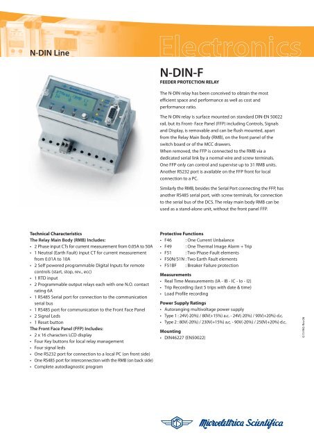
N-<strong>DIN</strong>-F<br />
FEEDER PROTECTION RELAY<br />
The N-<strong>DIN</strong> relay has been conceived to obtain the most<br />
efficient space and performance as well as cost and<br />
performance ratio.<br />
The N-<strong>DIN</strong> relay is surface mounted on standard <strong>DIN</strong>-EN 50022<br />
rail, but its Front- Face Panel (FFP) including Controls, Signals<br />
and Display, is removable and can be flush mounted, apart<br />
from the Relay Main Body (RMB), on the front panel of the<br />
switch board or of the MCC drawers.<br />
When removed, the FFP is connected to the RMB via a<br />
dedicated serial link by a normal wire and screw terminals.<br />
One FFP only can control and supervise up to 31 RMB units.<br />
Another RS232 port is available on the FFP front for local<br />
connection to a PC.<br />
Similarly the RMB, besides the Serial Port connecting the FFP, has<br />
another RS485 serial port, with screw terminals, for connection<br />
to the serial bus of the DCS. The relay main body RMB can be<br />
used as a stand-alone unit, without the front panel FFP.<br />
Protective Functions<br />
• F46 : One Current Unbalance<br />
• F49 : One Thermal Image Alarm + Trip<br />
• F51 : Two Phase-Fault elements<br />
• F50N/51N : Two Earth Fault elements<br />
• F51BF : Breaker Failure protection<br />
Measurements<br />
• Real Time Measurements (IA - IB - IC - Io - I2)<br />
• Trip Recording (last 5 trips with date & time)<br />
• Load Profile recording<br />
Power Supply Ratings<br />
• Autoranging multivoltage power supply<br />
• Type 1 : 24V(-20%) / 80V(+15%) a.c. - 24V(-20%) / 90V(+20%) d.c.<br />
• Type 2 : 80V(-20%) / 230V(+15%) a.c. - 90V(-20%) / 250V(+20%) d.c.<br />
Mounting<br />
• <strong>DIN</strong>46227 (EN50022)<br />
G15-ING-Rev.06
2<br />
Programmable Input Quantities<br />
In : Rated primary current of phase CTs : (1 ÷ 6500)A step 1A<br />
On : Rated primary current of earth fault detection CT0 : (1 ÷ 6500)A step 1A<br />
Fn : System frequency : (50 ÷ 60)Hz<br />
1F - 50/51 (I>): First Overcurrent Element<br />
Function enabling : Enable/Disable<br />
Current setting range : I> = (20 ÷ 400)%In step 1%In<br />
Definite trip time delay : tI> = (0.05 ÷ 60)s step 0.01s<br />
Time current curves : Indep.Definite Time (D), IEC (A / B / C)<br />
2F - 50/51 (I>>): Second Overcurrent Element<br />
Function enabling : Enable/Disable<br />
Current setting range : I>> = (20 ÷ 999)%In step 1%In<br />
Definite trip time delay : tI>> = (0.05 ÷ 60)s step 0.01s<br />
1F - 64 (Io>): First Earth Fault Element<br />
Function enabling : Enable/Disable<br />
Current setting range : Io> = (20 ÷ 9999)mAs step 1mAs<br />
Definite trip time delay : tIo> = (0.05 ÷ 60)s step 0.01s<br />
Time current curves : Indep.Definite Time (D), IEC (A / B / C)<br />
2F - 64 (Io>>): Second Earth Fault Element<br />
Function enabling : Enable/Disable<br />
Current setting range : Io>> = (20 ÷ 9999)mAs step 1mAs<br />
Definite trip time delay : tIo>> = (0.05 ÷ 60)s step 0.01s<br />
F49 (T>): Thermal Image element with prealarm<br />
Function enabling : Enable/Disable<br />
Temperature prealarm : Tal = (50 ÷ 110)%Tn step 1 %Tn<br />
Reset level : Tst = (10 ÷ 100)%Tn step 1 %Tn<br />
Time constant : tw = (1 ÷ 60)min step 1min<br />
F46 (I2>): Current Unbalance (negative sequence current) Element<br />
Function enabling : Enable/Disable<br />
Current setting range : I2> = (10 ÷ 99)%In step 1%In<br />
Definite trip time delay : tI2> = (0.1 ÷ 60)s step 0.1s<br />
Breaker Failure Element<br />
Trip time delay : tBF = (0.05 ÷ 0.75)s step 0.01s<br />
RMB<br />
FFP<br />
N-<strong>DIN</strong>-F<br />
G15-ING-Rev.06
35<br />
REMOVABLE<br />
FRONT FACE<br />
(FFP)<br />
PANEL<br />
CUT -OUT<br />
90<br />
96<br />
O3<br />
45<br />
Connection Diagram<br />
Overall Dimensions (mm)<br />
TRASPARENT COVER<br />
Dimension 45x108<br />
Height = 9<br />
1100 66<br />
FFP<br />
Height = 16<br />
85<br />
106<br />
RMB<br />
Height = 72<br />
3<br />
N-<strong>DIN</strong>-F<br />
50<br />
<strong>DIN</strong>46277<br />
(EN50022)<br />
G15-ING-Rev.06
4<br />
Typical Characteristics<br />
Rated Current In = 1/5A Programmable - On = 1/5A Programmable<br />
Metering range (0.01 ÷ 50)A<br />
Current overload 200 A for 1 sec; 10A continuous<br />
Burden on current inputs Zf = 3mW/phase for 5A (0.075VA @ 5A)<br />
Zo = 10mW/phase for 1A (0.01VA @ 1A)<br />
Auxiliary power supply Type 1- Type 2<br />
Average power supply consumption ≤ 7 VA<br />
Output relays rating 6 A; Vn = 250 V<br />
N-<strong>DIN</strong>-F<br />
Order code - Example :<br />
N-<strong>DIN</strong>-F 1 1<br />
Power Supply Relay<br />
1 = Type 1 1 = Standard (RMB+FFP)<br />
2 = Type 2 2 = Only RMB<br />
3 = Only FFP<br />
The performances and the characteristics reported in this document are not binding and can modified at any moment without notice.<br />
<strong>Microelettrica</strong> <strong>Scientifica</strong> S.p.A. - 20089 Rozzano (MI) - Via Alberelle 56/58 Italy<br />
Tel. +39 02 575731 - Fax +39 02 57510940 - E-Mail: sales.relays@microelettrica.com<br />
www.microelettrica.com<br />
btsadv.com G15-ING-Rev.06

![Linea LTHS, scheda tecnica (Rev. 0, agg. Giugno 2012) [PDF, 565 kB]](https://img.yumpu.com/15517969/1/184x260/linea-lths-scheda-tecnica-rev-0-agg-giugno-2012-pdf-565-kb.jpg?quality=85)