Module 2a Axial Exp.Joints BOA AG General - BOA Group
Module 2a Axial Exp.Joints BOA AG General - BOA Group
Module 2a Axial Exp.Joints BOA AG General - BOA Group

You also want an ePaper? Increase the reach of your titles
YUMPU automatically turns print PDFs into web optimized ePapers that Google loves.
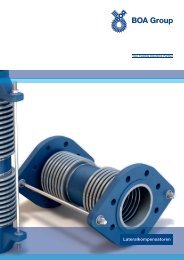
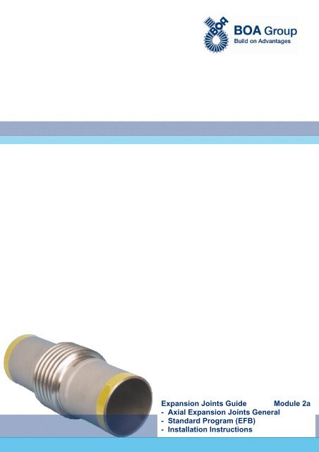
<strong>Exp</strong>ansion <strong>Joints</strong> Guide <strong>Module</strong> <strong>2a</strong>- <strong>Axial</strong> <strong>Exp</strong>ansion <strong>Joints</strong> <strong>General</strong>- Standard Program (EFB)- Installation Instructions
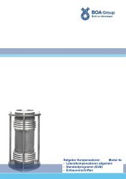
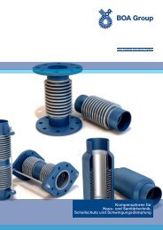
<strong>BOA</strong><strong>Exp</strong>ansion <strong>Joints</strong> Guide<strong>Exp</strong>ansion <strong>Joints</strong> GuideSummary <strong>Module</strong> <strong>2a</strong>1 AXIAL EXPANSION JOINTS GENERAL 32 STANDARD PROGRAM <strong>BOA</strong> AXIAL EXPANSION JOINTS (EFB) 52.1 <strong>General</strong> 52.2 Reduction 52.2.1 <strong>Exp</strong>ansion capacity 52.2.2 Temperature related movement and pressure reduction 62.3 <strong>Axial</strong> expansion joints with flanges 62.3.1 Type FS 62.3.2 Type FB 62.4 <strong>Axial</strong> expansion joints with weld ends 72.4.1 Type W 72.5 Small expansion joints 72.5.1 Small expansion joint Type Za (for welding into steel pipe) 72.5.2 Small expansion joint Type Ga (with thread for screwing in) 72.5.3 Small expansion joint Type I (for copper piping) 83 INSTALLATION INSTRUCTIONS AXIAL EXPANSION JOINTS 93.1 <strong>General</strong> safety recommendations 93.2 <strong>Axial</strong> expansion joints / Disassembly joints 103.3 Installation advice 11Elastomer Formed Bellows (EFB): several to multi-ply (2 to 16 layers) high flexibility short construction length low displacement forces big movement capacity small corrugation height vibration absorbing<strong>BOA</strong> <strong>AG</strong>Station-Ost 1CH-6023 RothenburgSwitzerlandPhone +41 41 289 41 11Fax +41 41 289 42 02sales@ch.boagroup.comwww.boagroup.com13-072
<strong>BOA</strong><strong>Exp</strong>ansion <strong>Joints</strong> Guide1 <strong>Axial</strong> <strong>Exp</strong>ansion <strong>Joints</strong> <strong>General</strong><strong>Axial</strong> expansion joints are intended to take up pipe expansion, particularly in the longitudinal direction of a straight pipe section. Even if an axialexpansion joint - depending on length and diameter of the bellows - can absorb small lateral deflections of only a few millimetres or can slightlyrotate angularly without parallelism at its end, such an effect should not be allowed and should never be the main function of the axial expansionjoint. The basic element of the axial expansion joint is the multi-ply bellows made of austenitic steel. To connect axial expansion joints tothe piping, they are provided with either weld ends or flanges, wherein the flanges are either of welded or collared type. Whilst collared flangeshave a raised face and can rotate, welded flanges are plane and firm. The standardization for certain types of expansion joints is also due toconstructional reasons. The piping designer can not achieve a higher movement capacity by installing two or more axial expansion joints inseries to get a double expansion joint or a unit of them. This approach would lead to lateral buckling of the bellows as the stability of the axiallyvery flexible bellows is separately calculated for each expansion joint type. The stability is depending on diameter and nominal pressure whichaffects primarily the sum of wall thickness of the individual layers. In their standard version, axial expansion joints may be supplied providedwith inner sleeve made of austenitic steel.CalculationsAnchor point loadThe task of anchor points in pipelines is to safely absorb the forces occurring in the pipeline, and to assign the thermal expansion to the individualsections of the line. The essential loads to be taken up by the anchor points using unrestrained expansion joints are:pressure thrust F Pspring rate of the bellows F Bsum of friction forces Σ F RPressure thrust F PThe pressure thrust tends to expand the bellows of the expansion joint. Since the pressure thrust is in almost all cases substantially bigger thanthe bellow’s spring force, no equilibrium condition can be established between both forces. Without anchor points, this would lead to overstretchingand thus the destruction of the bellows. The pressure thrust is calculated from the product of the bellow’s cross section area and thepressure. The effective cross section area A B [cm 2 ] is given in the technical data tables.F P = 10 · A B · pF P = axial pressure thrust [N]A B = effective cross section area [cm 2 ]p = pressure (operating and test pressure) [bar]Spring rate of the bellows F BThe bellows’ spring rate is the force the bellows opposes to its extension or contraction. The specific bellows spring rate per ± 1mm expansionis given in the technical data tables as spring rate C ax [N/mm].F B = C ax · XF B = spring rate of the bellows [N]C ax = spring rate taken from the table [N/mm] X = occurring pipe expansion [mm]Friction forces Σ F RThe pipe friction forces depend on the weight of the piping, including flow medium, insulation and the friction force coefficient of the pipe guide.Some empirical values for pipe guide friction force values :steel / steel 0.15 - 0.5steel / PTFE 0.1 - 0.25roller bearing 0.03 - 0.1F R = 9.81 · m L · F R = pipe friction force [N]m L = weight of piping including medium and insulation weight [kg] = pipe guide friction force value [-]3
For axial expansion joints, the major portion of the force to the anchor point results from the pressure thrust. <strong>Axial</strong> expansion joints are anelastic interruption of the pipeline. As a result of the operating pressure in the line, the pressure thrust is set free and must be taken up byappropriate anchor points (see fig. 1).Fig. 1Basically, we distinguish between main anchors and intermediate anchors.Main anchors are always positioned at the beginning and at the end of a pipeline, at points of direction changes and also at branching points,thus where full reaction forces occur (fig. 2).F H = F P + F B + F RF H = anchor point force [N]Fig. 2Intermediate anchor points are practically released from pressure thrust and take up only axially the spring rate of the expansion joint and thefriction forces of the pipe guides.F ZW = F B + F RF ZW = intermediate anchor point force [N]If local conditions do not allow the positioning of anchor points, restrained expansion joints must be installed.Details for the pipe layout, the design of pipe guides and prerestraint are described in detail in <strong>Module</strong> 1, starting from section 2.8.4
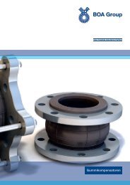
<strong>BOA</strong><strong>Exp</strong>ansion <strong>Joints</strong> Guide2 Standard Program <strong>BOA</strong> <strong>Axial</strong> <strong>Exp</strong>ansion <strong>Joints</strong> (EFB)2.1 <strong>General</strong><strong>Exp</strong>ansion joints manufactured by <strong>BOA</strong> <strong>AG</strong> Switzerland are formed in the elastomer process (EFB). The core element is the multi-ply metalbellows (2 to 16 layers) made of austenitic steel. <strong>Exp</strong>ansion joints produced by this method have a large expansion capacity and are veryflexible. They are especially appropriate to compensate for thermal expansion and minor misalignment during installation. Their advantagesare: <strong>BOA</strong> <strong>AG</strong> has over 70 years experience in manufacturing expansion joints multi-ply construction of the bellows, made of high-grade stainless steel (1.4571 and 1.4541), which means high resistance againstageing, temperature, UV-rays and most of aggressive media. very low spring rate due to the multi-ply construction of the bellows. large movements at short construction lengths due to reasonable stocks, various types in different sizes and pressure ranges are usually available at short time.Inner sleeveInner sleeves protect the bellows and prevent it from being stimulated to oscillate by the fluid. The installation of an inner sleeve is recommendedin the following cases: abrasive media large temperature variations flow rates higher than approx. 8m/s for gaseous media flow rates higher than approx. 3m/s for liquid mediaWhen installing, the flow direction must be observed!The designation for the design with/without inner sleeve for axial expansion joints (Types W, FS, FB) is the following:<strong>Exp</strong>ansion joint types marked with* are available either with or without inner sleeve (extra charge for inner sleeve).<strong>Exp</strong>ansion joint types marked "B" do not need an inner sleeve because of their short length.<strong>Exp</strong>ansion joint types marked "L" have always an inner sleeve.Example:Type FS16-3BType FS16-3LType FS16-2*= Basic version without inner sleeve= Basic version with inner sleeve= Basic version without inner sleeve, but may be equipped with inner sleeve.2.2 Reduction2.2.1 <strong>Exp</strong>ansion capacityNOTE (Hereinafter the term load cycle is used for full load change cycle.)The maximum permissible expansion capacity is indicated on the expansion joint. It refers to 1000 load cycles (for expansion joints conformingto EC standards: 500 load cycles with safety factor 2). At higher load cycles, the expansion capacity must be reduced by the load cycle factorK L according to table 1. For the accurate determination of the load factor K L the following formula can be applied:K L = (1000 / N adm ) 0.29Load cyclesN adm1'0002'0003'0005'00010'00030'00050'000100'000200'0001'000'00025'000'000Load cycle factorK L1.000.820.730.630.510.370.320.260.220.140.05 Table 15
2.2.2 Temperature related movement and pressure reductionNOTEThe admissible operating pressure is determined by the nominal pressure considering the reduction factor K P according to tab. 2. At highertemperatures, the expansion capacity K has to be reduced according to the reduction factors.Reduction factors 1) for pressure [K P ]and expansion capacity [K ]Temperature °C K P K -10...20501001502002503003504001.000.920.870.830.790.740.670.600.531)linear interpolation for intermediate values1.000.970.940.920.900.880.860.850.84 Table 22.3 <strong>Axial</strong> expansion joints with flanges2.3.1 Type FS expansion joints of type FS are equipped with flanges firmly welded onto the bellows; as a standard, flanges are made of carbon steel and are primer coated; as a standard, expansion joints of type FS are manufactured in nominal diameters from DN 40 to 1000 and inpressure ranges of PN 6, 10, 16, 25 and 40 (for DN 15 – 32 see type FS-Za „Technical Data“); the design type I or II is indicated in the last column of the standard tables (see fig.).Design I (single bellows)All types marked * and B are manufactured accordingly.Design II (double bellows to avoid buckling)Available only with inner sleeve.2.3.2 Type FB expansion joints of type FB are equipped with collared, movable flanges. The fluid is only in contact with the austenitic bellows material; as a standard, flanges are made of carbon steel and galvanized or primer coated (larger diameters). as a standard, expansion joints of type FB are manufactured in nominal diameters from DN 40 to 1000 and inpressure ranges of PN 6, 10, and 16; the basic version of type FB is manufactured without inner sleeve. Yet it can be equipped with one (extra charge)..Basic versionadditional designation B(without inner sleeve)additional designation L(with inner sleeve)6
2.4 <strong>Axial</strong> expansion joints with weld ends2.4.1 Type W expansion joints of type W are equipped with weld ends, firmly welded onto the bellows; as a standard, the weld ends are made of carbon steel and are primer coated; part of the weld connection area is colourless; as a standard, expansion joints of type W are manufactured in nominal diameters from DN 40 to 1000 and inpressure ranges of PN 6, 10, 16, 25 and 40 (for DN 15 – 32 see type Za). the design type I or II is indicated in the last column of the standard tables (see fig.)..Design IAll types with * and B are manufactured accordingly.Design II (double bellows to avoid buckling)Available only with inner sleeve.2.5 Small expansion joints2.5.1 Small expansion joint Type Za (for welding into steel pipe)Design with weld ends, supplied in prerestrained condition. The main element of this small expansion joint is the multi-ply bellows made ofaustenitic steel. The two weld ends for welding in are made of carbon steel St 52-3. The inner protection sleeve is reinforced and therefore alsoacting as a guiding tube. The outside sleeve protects the bellows from mechanical impacts. All connections are welded.Materials:bellows:stainless steel 1.4571 (similar to AISI 316 Ti)weld ends: carbon steel St 52-3inner protective sleeve: carbon steel St 35outside guiding tube: EN AW-6063 T6Application area:Absorption of axial movements in the supply network of heating and industrial lines.Nominal sizes: ½" – 2"For larger dimensions, expansion joints of type W are used.Pressure:Size ½" – 1 ¼": PN 16Size 1 ½" – 2": PN 10For higher pressures, expansion joints of type W are used.Endurance:5000 full load cycles at 25 mm movement(1000 full load cycles at 45 mm movement)Temperature resistance: up to 450°C2.5.2 Small expansion joint Type Ga (with thread for screwing in)Drinking water resistant, torsion-proof design, supplied in prerestrained condition, all connections are welded. The basic element of the smallexpansion joint is a <strong>BOA</strong> multi-ply bellows made of stainless steel. Both ends are equipped with male threads. The inner sleeve is reinforcedand therefore also acting as a guiding tube. During installation, the outside hexagonal sleeve helps gripping the wrench. By screwing in sockets,screw fittings or flanges, Type Ga covers all installation needs.7
Materials:bellows:stainless steel 1.4571 (AISI 316 Ti)connecting ends with male thread: stainless steel 1.4301 (AISI 304)inner protective sleeve: stainless steel 1.4301 (AISI 304)outside guiding tube, hexagonal: stainless steel 1.4301 (AISI 304)Application area:Absorption of axial movements in the service water network of sanitary installations.Nominal sizes: ½" – 2"For larger dimensions, expansion joints of type FB are used.Maximum temperature: PN 10 barFor higher pressures, expansion joints of type FB are used.Endurance:5’000 full load cycles at 25 mm movementTemperature resistance: up to 450°C2.5.3 Small expansion joint Type I (for copper piping)Drinking water resistant design, supplied in prerestrained condition, all connections are welded. The basic element of the small expansion jointis a <strong>BOA</strong> bellows made of bronze. Both connections are equipped with inner brazed ends. The inner sleeve is reinforced and therefore alsoacting as a guiding tube. The outside sleeve protects the bellows from mechanical impacts. By soldering in sockets, screw fittings or flanges,Type I covers all installation needs.Certified by SVGW (Swiss Gas and Water Association, Certificate # 8002-820)DN 15-28DN 35-42Materials:bellows:connecting ends:inner protective sleeve:outside guiding tube:bronze (CuSN6)copper (Cu-DHP)copper (Cu-DHP)copper (Cu-DHP)Application area:For taking up axial movements in copper piping used in sanitary and heating water systems.Nominal sizes:15-42 mmFor larger dimensions, expansion joints of type FB are used..Maximum pressure: PN 10 barFor higher pressures, expansion joints of type FB are used.Endurance:DN 15 - 28: 1’000 full load cycles (at 18 mm movement)DN 35 - 42: 5’000 full load cycles (at 25 mm movement)Temperature resistance: up to 180°C8
3.2 <strong>Axial</strong> expansion joints / Disassembly jointsDescription and application fields of axial expansion joints<strong>Axial</strong> expansion joints are intended to compensate for axial expansion movements in straight pipeline sections. In addition, they are used: for vibration absorption and reduction of structure born noise on pumps and compressors as flexible seals at the end of jacketed pipes in district heating systems to compensate for thermal expansion and vibrations in exhaust gas lines of boilers and engines as disassembly joints for pumps, valves and plate heat exchangers as gas-tight wall penetration of pipelines in reactor construction and shipbuilding to take up occurring differential expansion in vessel and apparatus constructionWeld endInner sleeveBellowsFig. 3Prerequisite for the application of axial expansions is the presence of appropriate anchor points and axial guide bearings. The technical datagiven on the rating plate are decisive for use.These installation and start-up instructions apply to the types listed in table 3.On site the general due diligence requirements to avoid corrosion damage must be observed, such as water treatment, or prevention of galvaniccorrosion in copper and galvanized pipes.Description and application fields for disassembly jointsDuring assembly of piping and any subsequent dismantling and replacement of individual components (valves, shut-off gates, pumps, etc.) formaintenance reasons, an axial gap is essential to comfortably set and exit the components. Often there is inaccuracy and misalignment due tolaterally displaced flanges. During operation of such systems also occur thermally induced expansions of pipe sections.Therefore, so-called disassembly joints are installed between pipes and components.Type overview<strong>BOA</strong> <strong>Axial</strong> expansion jointsnot prerestrained connectiontype50% prerestrained connectiontypeFS 2 Za 1FB 5 Ga 11W 1 I 10EXF 5EXW 1Connection type:1 weld end2 flange, welded5 flange, collared10 brazing fitting LF11 threaded nipple, weldedTable 310
3.3 Installation adviceAssembly Anchor points and pipe guides must be firmly installed before filling and pressure testing the system. <strong>Exp</strong>ansion joints must be installed without being subject to torsion. This applies particularly to expansion joints with socket connection. The steel bellows must be protected against damage and dirt (e.g. welding, plaster or mortar splatter). Steam pipelines should be installed in such a way that water hammers are avoided. This can be achieved by adequate drainage, insulation,by preventing water pockets and by sufficient inclination of the line. Observe the flow direction while installing expansion joints with inner sleeves. Avoid the installation of expansion joints in the immediate vicinity of pressure reducers, hot steam coolers and shut-down valves, if highfrequencyoscillations are expected due to turbulence. Otherwise special measures must be installed (e.g. thick-walled sleeves, perforateddisks, calming sections etc.). If high frequency vibrations or turbulence or high flow speed are expected, we recommend the installation of expansion joints with innersleeve. Inner sleeves are also recommended for expansion joints with DN ≥ 150, if the flow speed of air, gas or steam media exceeds 8 m/s, or3 m/s in case of liquid media.Steam / gasFlow s peed v [m/s]LiquidNominal size DNDiagram 1Pipe guides, pipe supports Provide inclination for drainage Align the pipeline, distance between pipe guides according to fig. 4, table 4 and diagram 2NOTESliding or roller supports are the safest measures to avoid buckling and lifting of the pipeline.CAUTIONSwing suspensions are not permitted adjacent to expansion joints!Fig. 4 = expansion capacity of the expansion joint [mm]L 1 = max. 2 x DN + /2 [mm]L 2 = 0.7 x L 3 [mm]L 3 = 400 x . DN [mm] valid only for steel pipelinesL 3 is the distance between the pipe supports according to the formula above. If buckling must be expected, L 3 must be reduced according todiagram 2..11
DN L 1 [mm] L 2 [mm] L 3 [mm]15 30 + 1050 155020 40 + 1200 175025 50 + 1400 200032 64 + 1550 225040 80 + 1750 250050 100 + 1950 280065 130 + 2250 320080 160 + 2500 3550100 200 + 2800 4000125 250 + 3100 4450150 300 + 3450 4900200 400 + 3950 5650250 500 + 4400 6300300 600 + 4850 6900350 700 + 5200 7450400 800 + 5600 8000450 900 + 5900 8450500 1000 + 6250 8900600 1200 + 6850 9800700 1400 + 7450 10600800 1600 + 7900 11300Table 4 (only valid for steel pipelines) Diagram 2Nominal size DNAnchor points Install main anchors at locations where the pipeline changes direction. Limit by anchors each pipe section to be compensated for.- Only one expansion joint is allowed between two anchors.- Main anchors must be installed at locations where the pipeline changes direction. They must take up the pressure thrusts of the expansionjoints as well as the frictional forces of the pipe supports/ guides.- Intermediate anchors must be installed if the movement capacity of one axial expansion joint is not sufficient to compensate for the entireexpansion of a long pipeline. In that case, several axial expansion joints are required.- In vacuum mode, the anchor points must be capable to take up tensile and pressure forces.Anchor pointGuide support<strong>Exp</strong>ansion jointAnchor pointGuide supportFig. 5Intermediate anchor between expansion jointsFig. 612
Vibration compensation The expansion joint should be installed as close as possible to the vibratingunit to make use of its entire absorption capacity. The vibration absorber must be installed as close as possible to the vibrationsource so as to avoid resonance of the other parts. Primarily it must be ensured that the vibration amplitude acts laterally, i.e.perpendicular to the vibration absorber axis. Install an anchor directly behind the expansion joint. Installation is madewithout prerestraint.Anchor pointVibrations in alldirectionsCAUTIONIf unrestrained vibration absorbers are installed, the reaction force must be takeninto account.UnitFig. 7PrerestraintAll common expansion joints must be installed prerestrained by 50% of theirmovement capacity (for heating systems: overall length of expansion joint plus50%, whereas for cooling systems: overall length of expansion joint minus 50% ofthe movement). If an expansion joint is not installed at the lowest operating temperatureof a heating system or at the highest operating temperature of a coolingsystem (e.g. repair of a still-warm pipe), an individual prerestraint mode must bechosen (see diagram 3).Fig. 8Prerestraint diagramTemperature difference in °C betweeninstallation and lowest temperatureThermal expansion of the pipeline at installation temperature in mmLength of pipeline in mTotal anticipated movement of the expansion joint in mmPrerestraint of the expansion joint in mmDiagram 313
Example for Diagram 3Order is placed for an axial expansion joint to be installed in a pipeline of 22 m length.Lowest temperature: –15°C.Highest temperature: +165°C.Max. expansion corresponding to 180°C heating = 50 mm.The expansion joint shall be restrained by 50% of this expansion = prerestrained by 25 mm, i.e. pulled apart.The remaining 50% = 25 mm will be compressed in operation mode.Special attention must be given to the restraint during installation. The temperature shall not be –15°C, but +20°C.This results in a corresponding expansion of the pipeline of 9 mm (see diagram 3), by which the expansion joint must be less prerestrained:25-9 = 16 mm.The prerestraint diagram (3) allows to determine the correct prerestraint value without intermediate calculation:1. Temperature difference between installation and lowest temperature: –15°C to +20°C = 35°C.2. Length of the pipe section to be compensated for: = 22 m.3. Draw a straight line from point "22 m pipe length“ to the "0°C" point.4. Draw a vertical line from the "35°C" point towards the beam coming from "22 m".5. Draw a horizontal line from this intersection to the line "Thermal expansion of pipeline in mm"; the result is, as stated above, 9 mm.6. Draw a straight line from the "9 mm" point to "Total anticipated movement" = 50 mm, and lengthen the connecting straight line to"Prerestraint of the expansion joint in mm".This results in a prerestraint value of 16 mm, which is the value by which the axial expansion joint must be pulled apart during installation.Installation of an expansion joint with flanges Align pipe axes and flange bolt holes.- ensure flanges are parallel- ensure gaskets are centred- tighten bolts crosswise. Make sure the expansion joint is not exposed to torsion during installation. After installation, check if the bellows convolutions are free of dirt.correctcorrectwrongwrongwrongFig. 914
Disassembly jointsNOTEDepending on the nominal diameter, the installation length EL of thedisassembly joint shall be max. 50 mm longer than the unrestrainedtotal length TL. Install anchor points on each side: With unrestrained expansionjoints the reaction force must be absorbed by the anchors.Fig. 10Installation Flange the disassembly joint to one pipe end (fig. 10). Onthe other side, pull the disassembly joint towards the components(valve, shut-off gate, pumps, etc.) either using longscrews (unrestrained) or with the supplied threaded rods (restrained)(fig.11). When installed correctly, the disassemblyjoint is restrained (fig. 12).Fig. 11Disassembly Loosen the extended screws or the threaded rods. - Thedisassembly joint swings back, creating a gap, which is necessaryfor comfortable subsequent assembly and disassemblyof the components.Fig. 1215
Subject to changes13-07<strong>BOA</strong> <strong>AG</strong>Station-Ost 1CH-6023 RothenburgSwitzerlandPhone +41 41 289 41 11Fax +41 41 289 42 02sales@ch.boaboagroup.comwww.boagroup.com16