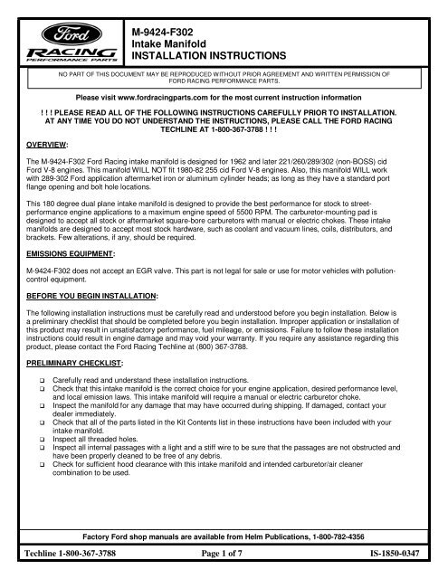
M-9424-F302 Intake Manifold INSTALLATION ... - Ford Racing Parts
M-9424-F302 Intake Manifold INSTALLATION ... - Ford Racing Parts
M-9424-F302 Intake Manifold INSTALLATION ... - Ford Racing Parts

Create successful ePaper yourself
Turn your PDF publications into a flip-book with our unique Google optimized e-Paper software.
M-<strong>9424</strong>-<strong>F302</strong><strong>Intake</strong> <strong>Manifold</strong><strong>INSTALLATION</strong> INSTRUCTIONSNO PART OF THIS DOCUMENT MAY BE REPRODUCED WITHOUT PRIOR AGREEMENT AND WRITTEN PERMISSION OFFORD RACING PERFORMANCE PARTS.Please visit www.fordracingparts.com for the most current instruction information! ! ! PLEASE READ ALL OF THE FOLLOWING INSTRUCTIONS CAREFULLY PRIOR TO <strong>INSTALLATION</strong>.AT ANY TIME YOU DO NOT UNDERSTAND THE INSTRUCTIONS, PLEASE CALL THE FORD RACINGTECHLINE AT 1-800-367-3788 ! ! !OVERVIEW:The M-<strong>9424</strong>-<strong>F302</strong> <strong>Ford</strong> <strong>Racing</strong> intake manifold is designed for 1962 and later 221/260/289/302 (non-BOSS) cid<strong>Ford</strong> V-8 engines. This manifold WILL NOT fit 1980-82 255 cid <strong>Ford</strong> V-8 engines. Also, this manifold WILL workwith 289-302 <strong>Ford</strong> application aftermarket iron or aluminum cylinder heads; as long as they have a standard portflange opening and bolt hole locations.This 180 degree dual plane intake manifold is designed to provide the best performance for stock to streetperformanceengine applications to a maximum engine speed of 5500 RPM. The carburetor-mounting pad isdesigned to accept all stock or aftermarket square-bore carburetors with manual or electric chokes. These intakemanifolds are designed to accept most stock hardware, such as coolant and vacuum lines, coils, distributors, andbrackets. Few alterations, if any, should be required.EMISSIONS EQUIPMENT:M-<strong>9424</strong>-<strong>F302</strong> does not accept an EGR valve. This part is not legal for sale or use for motor vehicles with pollutioncontrolequipment.BEFORE YOU BEGIN <strong>INSTALLATION</strong>:The following installation instructions must be carefully read and understood before you begin installation. Below isa preliminary checklist that should be completed before you begin installation. Improper application or installation ofthis product may result in unsatisfactory performance, fuel mileage, or emissions. Failure to follow these installationinstructions could result in engine damage and may void your warranty. If you require any assistance regarding thisproduct, please contact the <strong>Ford</strong> <strong>Racing</strong> Techline at (800) 367-3788.PRELIMINARY CHECKLIST:Carefully read and understand these installation instructions.Check that this intake manifold is the correct choice for your engine application, desired performance level,and local emission laws. This intake manifold will require a manual or electric carburetor choke.Inspect the manifold for any damage that may have occurred during shipping. If damaged, contact yourdealer immediately.Check that all of the parts listed in the Kit Contents list in these instructions have been included with yourintake manifold.Inspect all threaded holes.Inspect all internal passages with a light and a stiff wire to be sure that the passages are not obstructed andhave been properly cleaned to be free of any debris.Check for sufficient hood clearance with this intake manifold and intended carburetor/air cleanercombination to be used.Factory <strong>Ford</strong> shop manuals are available from Helm Publications, 1-800-782-4356Techline 1-800-367-3788 Page 1 of 7 IS-1850-0347
M-<strong>9424</strong>-<strong>F302</strong><strong>Intake</strong> <strong>Manifold</strong><strong>INSTALLATION</strong> INSTRUCTIONSNO PART OF THIS DOCUMENT MAY BE REPRODUCED WITHOUT PRIOR AGREEMENT AND WRITTEN PERMISSION OFFORD RACING PERFORMANCE PARTS.Check that you have all of the parts required for the installation. These include the intake manifold gasketset, gasket adhesive, RTV silicone sealant, and pipe thread sealant as shown in the <strong>Parts</strong> Required list inthese installation instructions.Check that you have all the tools you will need to perform the intake manifold installation. A recommendedbut not exhaustive list is located in these installation instructions.Check that you have the proper intake manifold fasteners for this application.If using your old carburetor, before you remove it from the engine make sure it is working properly and thatthe carburetor is tuned properly. Consult the shop manual or installation instructions for that carburetor todetermine if the carburetor is in proper tune.If you are using a new carburetor, make sure you have read and understand the installation instructions forthat carburetor and that the initial adjustments are within the manufacturer’s specifications.Before removing your old intake manifold, make sure that your ignition system is in good working order;check and note the current ignition timing. Make sure the timing marker is legible and understandable. Withthe engine at top dead center on the #1 cylinder, note and mark the orientation of the distributor body to theengine and the orientation of the rotor to the distributor body. This will aid in the re-installation of thedistributor. Consult these installation instructions and your vehicle’s shop manual for specific instructions.Before removing your old intake manifold, check the adjustment of your automatic transmission kick-downlinkage to make sure it is adjusted properly. Consult your shop manual and make sure that you understandthe kick-down linkage adjustment and how to properly adjust it when you install your new intake manifold.Before removing your old intake manifold, check all of your fuel, water, and vacuum hoses and theirconnections. Make sure that there are no leaks and that the hoses are in good condition. Mark the locationsof your hoses making sure that there is a corresponding location on your new intake manifold for all of thehose fittings and gauge sensors. Fittings and hoses that are not in good condition should be replaced.KIT CONTENTS:(1) M-<strong>9424</strong>-<strong>F302</strong> intake manifold(3) 3/8 NPT hex pipe plug(1) 1/2 NPT hex pipe plug(1) Installation instructionsPARTS REQUIRED:NOTE: It will be necessary to purchase some of the parts listed below (or their equivalents) in order to properlycomplete the manifold installation. Determination of equivalency is the responsibility of the consumer. <strong>Ford</strong><strong>Racing</strong> does not assume that responsibility. <strong>Intake</strong> manifold gasket set. M-9439-A50 is recommended Thermostat housing gasket Valve cover gasket set Oil-resistant, silicone-based sealant (Permatex silicone form-a-gasket, Dow Corning Silastic, or equivalent) Spray gasket adhesive (Fel-Pro spray tack, P/N 220) Carburetor-base gasket (usually supplied with carburetor) Thread sealer (Loctite 565, Permatex P/N 56521)Factory <strong>Ford</strong> shop manuals are available from Helm Publications, 1-800-782-4356Techline 1-800-367-3788 Page 2 of 7 IS-1850-0347
M-<strong>9424</strong>-<strong>F302</strong><strong>Intake</strong> <strong>Manifold</strong><strong>INSTALLATION</strong> INSTRUCTIONSNO PART OF THIS DOCUMENT MAY BE REPRODUCED WITHOUT PRIOR AGREEMENT AND WRITTEN PERMISSION OFFORD RACING PERFORMANCE PARTS.NOTE: Never install tapered (pipe) fittings in an aluminum manifold dry without thread sealer, or thread damagewill occur.TOOLS REQUIRED:Socket wrench set 3/8”-drive ratchet and extensionsOpen end wrenches 3/8” to 1”Box end/flare wrenches (optional)10” adjustable wrench (crescent)Ignition wrench setScrewdrivers, standard and Phillips, various lengthsGasket scraperNeedle nose pliersDrain bucketTiming lightTorque wrenchFile5/16-18 NC thread chaser, or tap (for cleaning bolt holes)Vacuum gaugeOTHER USEFUL SUPPLIES:Engine coolantShop towels, paper and/or clothPad and pencilEngine oilMasking tapeModeling clay<strong>INSTALLATION</strong> INSTRUCTIONS:These instructions are designed to cover a wide variety of vehicle applications. If your vehicle is not equipped withany items referred to in these instructions, such as transmission kick-down linkage, air conditioning, or powerbrakes, proceed to the next step. Also, if you are unfamiliar with any of the procedures in these instructions, consulta shop manual for your vehicle and engine application.CHECK FOR ADEQUATE HOOD HEIGHT:1. We recommend making several columns of modeling clayand placing them on your air cleaner in various positions.2. Close the hood completely and then reopen it.3. Measure the clay columns and record your hood clearance.4. Compare the A-B height (see NOTE below) of your old intakemanifold with your new intake manifold. Also consider thatthe carburetor/air cleaner combination determines thedifference in the air-cleaner-to-hood clearance.NOTE: Lay straight edge across carburetor mounting pad. Measure from manifold front and rear sealsurfaces to bottom of straight edge. Check stock manifold height in same manner and compare.Factory <strong>Ford</strong> shop manuals are available from Helm Publications, 1-800-782-4356Techline 1-800-367-3788 Page 3 of 7 IS-1850-0347
M-<strong>9424</strong>-<strong>F302</strong><strong>Intake</strong> <strong>Manifold</strong><strong>INSTALLATION</strong> INSTRUCTIONSNO PART OF THIS DOCUMENT MAY BE REPRODUCED WITHOUT PRIOR AGREEMENT AND WRITTEN PERMISSION OFFORD RACING PERFORMANCE PARTS.MANIFOLD REMOVAL PROCEDURE:STEP 1:STEP 2:STEP 3:STEP 4:Disconnect the ground cable from the battery.Clean any loose debris, dirt, and grease from the top of the engine adjacent to the intake manifoldand valve covers. This will help prevent harmful debris from falling into the engine during theinstallation process.Identify the vacuum and crankcase ventilation hoses (if any) leading to the air cleaner and note therouting and connection points. Remove the air cleaner.Prior to removing any other vacuum lines, identify the routing of the lines. Mark and remove thevacuum lines from the carburetor and/or intake manifold.WARNING: Hot water and steam may be present if the engine is still warm.STEP 5:STEP 6:STEP 7:STEP 8:STEP 9:STEP 10:Drain the radiator (it may be necessary to remove the bottom radiator hose if there is no drain plugin the radiator).Disconnect the throttle linkage, transmission kick-down linkage (automatic transmission only), andchoke hot air tube (if applicable).Loosen the gas cap to relieve pressure from the fuel system. Disconnect the fuel line at thecarburetor. Plug the end of the fuel line to prevent leakage.Remove the carburetor.Tag and disconnect the ignition coil and sensor wires. Remove the ignition coil bracket and the coil.Remove the upper radiator hose, thermostat housing, and thermostat.NOTE: For early 289 engines, the thermostat receiver counterbore is located in the intake manifold. On the latermodels, it is located in the thermostat housing. If you have an early style thermostat housing, you will need toreplace it with a late model thermostat housing.STEP 11:STEP 12:STEP 13:STEP 14:Remove all water and vacuum fittings from the manifold.Remove all remaining brackets (if any) from the manifold.Loosen and remove the valve covers to assist in the manifold removal and the new manifold installation.DISTRIBUTOR REMOVAL PROCEDURE: Removal of the distributor is not required on this engineapplication to remove the intake manifold. If you choose to remove the distributor, please follow theseinstructions and follow your shop manual for your vehicle’s application.Factory <strong>Ford</strong> shop manuals are available from Helm Publications, 1-800-782-4356Techline 1-800-367-3788 Page 4 of 7 IS-1850-0347
M-<strong>9424</strong>-<strong>F302</strong><strong>Intake</strong> <strong>Manifold</strong><strong>INSTALLATION</strong> INSTRUCTIONSNO PART OF THIS DOCUMENT MAY BE REPRODUCED WITHOUT PRIOR AGREEMENT AND WRITTEN PERMISSION OFFORD RACING PERFORMANCE PARTS.CAUTION! FOLLOW THESE INSTRUCTIONS CAREFULLY, AS SERIOUS DAMAGE CAN OCCUR WHENTHE IGNITION IS NOT RE-INSTALLED CORRECTLY.• Set the engine on Top Dead Center (after compression stroke) for #1 cylinder using the crankshaft timingmarker. There are two different firing orders for 289 & 302 <strong>Ford</strong> engines. Early engines use the 15426378firing order, while late engines use the 13726548 firing order. The easiest way to check is to note therouting of your spark plug wires.• Remove the distributor cap.• Note the position of the rotor and make a mark on the distributor body in line with the rotor tip (it shouldpoint to the position of the cylinder #1 spark plug wire on the distributor cap).• Note the position of the distributor vacuum canister (or other distributor body feature) and place sometype of reference mark on a convenient surface not attached to the intake manifold.• Note the position of the points: if open, how much; if closed, note the distance from the point block to thecam lobe. If the distributor has a magnetic pickup, note the position of the trigger wheel with respect tothe pickup.• Remove the distributor. DO NOT rotate the engine after removing the distributor (but if you do, thecrankshaft timing marker is your reference).STEP 15:STEP 16:Remove the 12 intake manifold-to-cylinder head bolts.Remove the intake manifold. If the intake manifold is stuck hard to the mounting flanges, DO NOTpry against cylinder head port flanges, as they could become damaged and compromise the gasketsealing with your new intake manifold. Double-check that all of the bolts have been removed andpry upward carefully at the engine block end seal surfaces.INSTALLING YOUR NEW MANIFOLD:STEP 1:STEP 2:Clean the cylinder head port flange and the engine block end seal surfaces. To prevent gasketpieces from falling into ports and the lifter valley when cleaning old gaskets from head surfaces,stuff paper towels into all the ports and lay rags in the lifter valley. When clean, carefully remove thepaper towels from the cylinder head ports and then the rags from the lifter valley. Make sure that allparticles that fell on the rags are completely removed. Wipe surfaces with rags soaked in solvent,such as brake cleaner or lacquer thinner, to remove any oils or grease. This is a must for propermanifold/gasket sealing.Trial fit the intake gaskets to the cylinder heads and intake manifold. Make sure that the portopenings in the gaskets are not too big or small, to where they could cause leakage.Factory <strong>Ford</strong> shop manuals are available from Helm Publications, 1-800-782-4356Techline 1-800-367-3788 Page 5 of 7 IS-1850-0347
M-<strong>9424</strong>-<strong>F302</strong><strong>Intake</strong> <strong>Manifold</strong><strong>INSTALLATION</strong> INSTRUCTIONSNO PART OF THIS DOCUMENT MAY BE REPRODUCED WITHOUT PRIOR AGREEMENT AND WRITTEN PERMISSION OFFORD RACING PERFORMANCE PARTS.STEP 3:STEP 4:STEP 5:STEP 6:STEP 7:Apply a thin coat of gasket adhesive to the cylinder head side of the intake gasket surfaces and thecylinder head port flanges. Allow the adhesive to completely dry. Lay the manifold gaskets in place,making sure that gaskets are adhered to the cylinder head port flange and will not slip from theirproperly installed positions.Trial fit your new intake manifold before applying any RTV silicone sealant. Place the new intakemanifold into position; check that it sits down, properly seated on the intake manifold gaskets.There should be gap between the engine block and the manifold at the end seal surfaces. Check tomake sure all of the intake manifold bolts can be installed. Make sure that the bolts have at leastnine turns of thread engagement and that they do not bottom in the bolt holes. The use of a .090”-.125” thick by 5/8”-3/4” O.D. washer under each intake manifold mounting bolt is highlyrecommended. If there are any other fit issues such as hood clearance or installation ofcomponents dependent on the manifold, they should be checked at this time.When you are fully prepared to install the intake manifold, apply a ¼”-wide bead of oil-resistant RTVsilicone sealant to the front and rear block-sealing surfaces, making sure to overlap manifoldgaskets at all four corners. Do not use the cork or rubber end seal gaskets included in thegasket set. Apply a light film of RTV silicone sealant around the water passage openings.Carefully, lay your <strong>Ford</strong> intake manifold in place. If the manifold must be moved, the RTV siliconesealant may need to be cleaned and re-applied. For the bolts to be installed in bolt holes that aredrilled through, apply a dab of thread sealer on the threads. For the blind bolt holes, apply a drop ofmotor oil to the bolt threads. Install the intake bolts initially torquing to 5 ft./lbs., then 10 ft./lbs.,following the factory <strong>Ford</strong> sequence (see below), and finally torque to 15-18 ft./lbs. Do not overtorquethe intake manifold mounting bolts. Over-tightening these bolts can result in broken flangesor damage to the cylinder head threaded bolt holes.Install the thermostat, gasket, and thermostathousing. Be sure that the thermostat housing is ingood condition and has been cleaned of any oldgasket material. If the mounting flange on thethermostat housing is not flat or is damaged,replace it before continuing.NOTE: For early 289 engines, the thermostat receivercounterbore is located in the intake manifold. On the latermodels, it is located in the thermostat housing. If you havean early style thermostat housing, you will need to replace itwith a late model thermostat housing.STEP 8:STEP 9:Install the heater hose fitting, heater hose, and radiator hoses. Use thread sealer on the threads ofthe heater hose fitting.Install the gauge sensors and vacuum fittings into the manifold. Use thread sealer on the pipethreads of the sensors and fittings. Install pipe plugs in any unused water and vacuum ports in themanifold (plugs have been provided in the kit).Factory <strong>Ford</strong> shop manuals are available from Helm Publications, 1-800-782-4356Techline 1-800-367-3788 Page 6 of 7 IS-1850-0347
M-<strong>9424</strong>-<strong>F302</strong><strong>Intake</strong> <strong>Manifold</strong><strong>INSTALLATION</strong> INSTRUCTIONSNO PART OF THIS DOCUMENT MAY BE REPRODUCED WITHOUT PRIOR AGREEMENT AND WRITTEN PERMISSION OFFORD RACING PERFORMANCE PARTS.STEP 10:STEP 11:STEP 12:STEP 13:STEP 14:STEP 15:STEP 16:STEP 17:STEP 18:STEP 19:STEP 20:STEP 21:STEP 22:Install the distributor (if removed) orienting the rotor and the distributor body according to thereference marks made before the distributor was removed (Distributor Removal Section). Makesure that your distributor engages the oil pump drive shaft and seats properly down against theengine block. Install the distributor clamp and tighten the bolt just enough that the distributor bodycan still be rotated by hand.Install your four carburetor studs in the manifold. Place the carburetor gasket on the cleancarburetor pad. Do not use any type of sealant on the carburetor gasket.Install the carburetor. Connect all linkage and throttle springs.Connect all vacuum and fuel lines. Refer to your tags or drawings for correct placement.Automatic transmissions only: Adjust kick-down or throttle pressure linkage for proper shiftpoints (refer to your vehicle’s shop manual for the proper adjustment procedure). Check alllinkages, making sure that they function freely.Reinstall valve covers and new gaskets.Install the A/C and coil brackets, coil, wires, and all brackets that were removed from the manifold.Close the drain and fill the radiator to the proper level with coolant. While filling, allow trapped air tobleed from the intake manifold at the heater hose fitting until coolant flows from the fitting. Then, reinstallthe heater hose and continue adding coolant to the proper level.IMPORTANT! Change the oil to remove any coolant or debris that may have contaminated thecrank case.Retighten the gas cap and connect the battery cable.Hook up the timing light and start the engine. Set the timing to factory specs. Tighten the distributor.Check for possible fuel, oil, or coolant leaks and for proper choke operation.Install the air cleaner.CAUTION! Check to be sure that there is adequate clearance for the throttle and choke linkages throughtheir full range of travel.IMPORTANT: Check for adequate hood clearance before closing the hood.STEP 23:STEP 24:Operate the engine for 30 minutes. Allow the engine to cool and re-torque the manifold boltsfollowing STEP 6 on page 6 of these instructions.YOUR MANIFOLD <strong>INSTALLATION</strong> IS COMPLETE.Factory <strong>Ford</strong> shop manuals are available from Helm Publications, 1-800-782-4356Techline 1-800-367-3788 Page 7 of 7 IS-1850-0347