AM SERVICE TRAINING - Hoshizaki America, Inc.
AM SERVICE TRAINING - Hoshizaki America, Inc.
AM SERVICE TRAINING - Hoshizaki America, Inc.
Create successful ePaper yourself
Turn your PDF publications into a flip-book with our unique Google optimized e-Paper software.
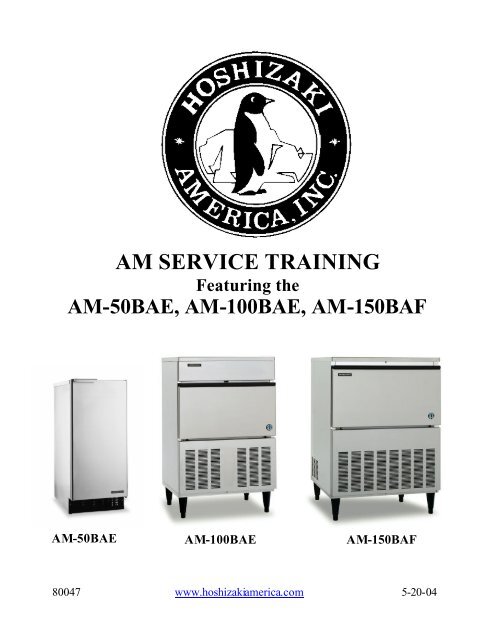
<strong>AM</strong> <strong>SERVICE</strong> <strong>TRAINING</strong>Featuring the<strong>AM</strong>-50BAE, <strong>AM</strong>-100BAE, <strong>AM</strong>-150BAF<strong>AM</strong>-50BAE <strong>AM</strong>-100BAE <strong>AM</strong>-150BAF80047 www.hoshizakiamerica.com 5-20-04
All <strong>AM</strong> models have similar sequence of operation. This manual is designed as ageneric <strong>AM</strong> Training manual.The <strong>Hoshizaki</strong> <strong>AM</strong> series ice machine uses ahorizontal evaporator design which forms aunique cube shape.20mm25mmThe compact <strong>AM</strong>-50BAE unit is 14 7/8”w x22 5/8”d x 33 1/2”h and is designed forcounter-top, under-counter, or freestandinginstallations with up to 51 pounds ofproduction and 30 pounds of storageThe <strong>AM</strong>-100 and <strong>AM</strong>-150 are for undercounter or free standing applications.The <strong>AM</strong>-100 dimensions are 24 15/16”w x20 1/2”d x 39”h with 6” legs and canproduce up to 105 and pounds with 44pounds of storage.The <strong>AM</strong>150 measures 27 11/16”w x 2715/16”d x 39”h with 6” legs and productionup to 150 pounds with 88 pounds of storage.- 2 -
(<strong>AM</strong>-50)The horizontal evaporator and waterdistribution system are unique to the<strong>Hoshizaki</strong> <strong>AM</strong> and IM series. The <strong>AM</strong> andthe IM series are similar in the fact that theyboth make ice on a horizontal evaporator.The <strong>AM</strong> evaporator design however isdifferent, as shown in the center picture. Themoving IM water plate and associated partsare eliminated with this simple design.The <strong>AM</strong>-50BAE produces 24 cubes and .60pounds per cycle. The <strong>AM</strong>-100BAE and<strong>AM</strong>-150BAF produce 60 cubes and 1.54pounds per cycle.The <strong>AM</strong> series sequence of operation is alsodifferent. The sequence of operation for the<strong>AM</strong> series will be explained in the followingpages.(<strong>AM</strong>-100 & <strong>AM</strong>-150)- 5 -
THERMISTORThermistorThe <strong>AM</strong> series uses a combinationthermistor and control board to control thesequence of operation. When the toggleswitch is placed in the “ON” position andthe bin control calls for ice, the unit willbegin in the initial harvest cycle. Startingthe unit in harvest allows the compressor tostart in an unloaded condition, greatlyextending the life of the compressor. Thisoperation is common among all <strong>Hoshizaki</strong>cube icemakers.During the initial harvest, the compressor,hot gas valve and water valve will beenergized. The initial harvest is a timedharvest. After 50 seconds, the control boardwill energize the X1 board relay to start thepump motor and condenser fan motor,switching the unit into the freeze cycle.After the initial harvest, the X2 board relaywill remain energized during the freezecycle. This allows the water valve to feedfresh water for an additional 50 seconds.This extended fill, only takes place when theunit has restarted from a power interruptionor when the bin control calls for ice. Duringthe normal harvest cycle the water valvewill de-energize at the beginning of freezeor in the event of long harvest the valve willhave a maximum open time of 102 seconds.This could occur in the event of operation inlow water and ambient temperatures. Duringnormal operating conditions the unit willrun approximately 2~4 minutes in theharvest cycle.- 6 -
Throughout the freeze cycle, whichnormally last 14~33 minutes, depending onmodel and operating conditions, the unitwill continue to circulate the water from thereservoir to the horizontal evaporator,through the spray tubes. When thetemperature of the evaporator has reachedapproximately 26.6°F (-3°C) and thethermistor signals approximately 6.8KΩ thefreeze completion timer will start and countdown 8 minutes.Note:*A thermistor temperature of26.6°F (-3°C) will start 8 minutefreeze completion timer.*A thermistor temperature of44.6°F (7°C) will start the 50second defrost completion timer.* 26.6°F (-3°C) = 6.8KΩthermistor resistance.* 44.6°F (+7°C) = 4.5KΩthermistor resistance.The control board will then switch to normalharvest, re-energize the X2 relay and deenergizethe X1 relay. This opens the hotgas valve and water valve and de-energizesthe condenser fan motor and water pump. Anormal harvest is temperature and timeterminated and uses the same thermistorused to terminate the freeze cycle. After theevaporator warms to approximately 44.6°F(+7°C) the thermistor signals the controlboard with a resistance of approximately4.5KΩ. The control board then starts theharvest completion timer, which is set at 50seconds. When this timer completes 50seconds, it ends the harvest cycle and beginsfreeze.The unit will continue to cycle betweenfreeze and harvest until the bin controlopens, signaling a full bin or until power isinterrupted- 7 -
The <strong>AM</strong> series uses a thermostatic bincontrol located on the right rear side of theice storage compartment. This control willopen when ice touches the sensing bulb andthe unit will shut downThis control includes a small heater toeliminate the control opening due to lowambient temperatures in the bin.Access the control by removing the wiringchannel from the rear of the unit.The thermostatic bin control is factory setand should shut down the unit within 10seconds after ice contacts the bulb.Adjustment may be necessary in higheraltitudes.- 8 -
<strong>AM</strong>-50BAE: The control switch is marked“ICE- OFF-WASH” and is located on thelower right front of the unit.<strong>AM</strong>-100 & <strong>AM</strong>-150: The control switch islocated on the control box which is locatedbehind the front panel on the left hand sideof the unit.(<strong>AM</strong>-50BAE)If it is necessary to gain access to the controlbox, the louvered panel must be removed.<strong>AM</strong>-50BAE: This can be done by removingthe two screws from the lower portion of thefront panel and pulling the panel downslightly to dis-engage the mounting tabs.<strong>AM</strong>-100 & <strong>AM</strong>-150: Remove the middlescrew at the bottom of the front panel and liftoff.(<strong>AM</strong>-100 & <strong>AM</strong>-150)(<strong>AM</strong>-50BAE)The control box is held in place with 2 hexhead bolts. Once the bolts are removed,<strong>AM</strong>-50BAE: The control box can be rotatedapproximately 45° CCW allowing easieraccess to the control box cover and controlboard.<strong>AM</strong>-100 & <strong>AM</strong>-150: The control box can bepulled out to the front of the unit after thetwo bolts have been removed.(<strong>AM</strong>-100 & <strong>AM</strong>-150)- 9 -
CONTROL BOARD:A solid state board controls the <strong>AM</strong>operation. The control board is factoryadjusted to produce consistent ice in allambient conditions.“NO SEASONALADJUSTMENTS AREREQUIRED”VR1 & VR2are factory adjusted.Red paint seals thesetting for VR1 &VR2 at this point.There are no adjustments needed, howeverthere are two variable resistors on the controlboard. The first resistor VR1 is used to finetune the harvest termination temperatureadjustment when the control board ismanufactured. The adjustment is sealed withred paint and should always remain in thefactory setting.VR2 is set from the factory so that the icemachine will perform at the optimum level.This resistor adjusts the freeze cycletermination setting so the proper cube size isobtained. The VR2 setting is also sealed withred paint and should not be changed.If you find that the red seal is broken, theboard will need to be replaced since thesesettings cannot be correctly adjusted in thefield. The replacement board will be factoryset and sealed for proper operation.- 10 -
Preventative maintenance for the <strong>AM</strong> issimple. Follow these steps to allow the unitto operate efficiently.1. Clean the condenser once a year using abrush or vacuum.2. Check and clean the inlet water valvescreen as needed to assure proper waterflow.*Remember that the original fitting is a 3/4” BSPand the use of a standard MPT fitting willdamage the threads. In May of 2003, this fittingwas changed to 3/8” male flare. After Augustand September of 2003, this fitting was changedto a 1/2" FPT.3. Clean and sanitize the water distributionsystem annually using the recommendedcleaner. (See the next page for detailedinformation on cleaning the watersystem)4. Wipe down the exterior using a soft clothand neutral cleaner.The <strong>AM</strong> series uses a magnetic pump. Thisstyle of pump allows the water portion of thepump to be completely sealed from themotor. This eliminates the need for amechanical seal and eliminates thepossibility of water entering the pumpthrough the pump end.If the pump does not pump and is beingenergized then remove the four screws fromthe front of the pump and check for anydebris that may be binding the impeller- 11 -
Cleaning tips:• A detailed cleaning label is located on theback of the icemaker door of the <strong>AM</strong>-50BAE or on the back of the bin baffle ofthe <strong>AM</strong>-100 & <strong>AM</strong>-150. More detailedinstructions are included in the customersInstruction Manual or in the productService Manual. This manuals can beviewed at www.hoshizaki.com• Always follow the cleaning instructionsand use the recommended ice machinecleaner.Water circuit disassemblyThe following instructions provideinformation on the disassembly of the watercircuit. Before starting these steps it will benecessary to remove the hinged slope fromthe pins at the front edge of the bin.Remove each Separator by lifting it to thehorizontal position and pushing it hardinward. Remove all the separators the sameway, clean and sanitize them- 12 -
Disconnect the suction tube that connectsthe pump motor to the sump tank.(<strong>AM</strong>-50)The <strong>AM</strong>-50BAE has a locking tabs that canbe released by compressing both plastic tabsto unlock the joint in the direction of theblack arrows and pulling the pipe clear todrain the Tank.<strong>AM</strong>-100BAE & <strong>AM</strong>-150BAF simply pullthe pipe of the connector(<strong>AM</strong>-100 & <strong>AM</strong>-150)<strong>AM</strong>-50: Spread out the tabs on both sides tounlock the water tank, and pull it out towardyou. Clean and sanitize the water tank.(<strong>AM</strong>-50BAE)(<strong>AM</strong>-100 & <strong>AM</strong>-150)<strong>AM</strong>-100 & <strong>AM</strong>-150: Remove thethumbscrews on both sides of the water tankand pull it out toward you. Clean andsanitize the water tank- 13 -
<strong>AM</strong>-50BAE: Lift off the ice chute from thefront frame pipe and then from the rearframe pipe clean and sanitize the ice chuteThe <strong>AM</strong>-100 & <strong>AM</strong>-150: ice chute isincorporated into the water plate and will beremoved as one assembly in the next step.Check to see if cube guide pulls out withsump tank(<strong>AM</strong>-50)Pull the discharge tube from the sprayassembly. Remove the assembly by pullingit toward you.(<strong>AM</strong>-100 & <strong>AM</strong>-150)(<strong>AM</strong>-50)Remove the caps to clean and sanitize thespray assembly. If the nozzles are clogged,clean them with a small wire or suitablebrush.(<strong>AM</strong>-100 & <strong>AM</strong>-150)- 14 -
<strong>AM</strong>-50: Position and lock the ice chute on tothe front and rear frame pipes by pushing thechute down until it clicks(<strong>AM</strong>-50)(<strong>AM</strong>-100 &<strong>AM</strong>-150)<strong>AM</strong>-100 & <strong>AM</strong>-150: Place the rear of thewater tank on the water tank rest at the backof the storage bin. Use the thumbscrews tosecure the front of the water tank to themechanism base.<strong>AM</strong>-50: Slide in the water tank along therails at the bottom of the right and leftbrackets until it clicks into place- 16 -
<strong>AM</strong>-50BAE: Refit the suction tube on to thewater tank inlet by pushing the joint to lockit securely in the arrow directions.(<strong>AM</strong>-50)The <strong>AM</strong>-100 & <strong>AM</strong>-150 uses a simple pushon suction hose.(<strong>AM</strong>-100 & <strong>AM</strong>-150)Note: A loose fitting may cause a waterleak.Hook each separator on the rail and pull ithard toward you until it locks in place with aclick. Refit all the separators in the sameway.Refit the bin slope in its correct position- 17 -
<strong>AM</strong>-50BAE- 18 -
- 19 -
- 20 -
<strong>AM</strong>-50BAEElectrical Specifications:The unit is 115 volt/ 60 hz. /1ph.The <strong>AM</strong>-Series should be connected to a separate 15Amp circuit.- 21 -
<strong>AM</strong>-100BAEElectrical Specifications:The unit is 115 volt/ 60 hz. /1ph.The <strong>AM</strong>-Series should be connected to a separate 15Amp circuit.- 22 -
<strong>AM</strong>-150BAFElectrical Specifications:The unit is 115 volt/ 60 hz./1ph.The <strong>AM</strong>-Series should be connected to a separate 15Amp circuit.- 23 -
<strong>AM</strong>-50BAE & <strong>AM</strong> -100BAE<strong>AM</strong>-50BAE R-134a 4.2 oz<strong>AM</strong>-100BAE R-134a 6.6 ozThermistorLow side process tubeHigh side process tubeNote: All <strong>Hoshizaki</strong> ice machines are critically charged. Since the <strong>AM</strong>-series have small refrigeration circuits and the <strong>AM</strong>-100 and <strong>AM</strong>-150 use cap tube systems this is especially true. The <strong>AM</strong>-series does not come from the factory with any typeof refrigeration system access. In the event that the system must be accessed for troubleshooting it will be necessary toinstall piercing type “saddle valve” on the system. These valves should only be installed on the process tubes provided onthe low side and high side of the system. After the repair has been made to the unit, sweat type schraders should be installedin place of the piercing valves.Again, these units are critical charged. Every precaution should be taken to insure that the exact charge of R134a for the<strong>AM</strong>-50 and <strong>AM</strong>-100 and R-404a for the <strong>AM</strong>-150 is weighed - 24 into - the system. Due to the very small charge of these units ,extra care must be taken to avoid any refrigerant loss when removing gauges.
<strong>AM</strong>-150BAFWATER AND REFRIGERATION CIRCUIT<strong>AM</strong>-150BAF 9.5oz R-404aLow side process tubeHigh side process tubeNote: All <strong>Hoshizaki</strong> ice machines are critically charged. Since the <strong>AM</strong>-series have small refrigeration circuits this isespecially true. The <strong>AM</strong>-series does not come from the factory with any type of refrigeration system access. In the eventthat the system must be accessed for troubleshooting it will be necessary to install piercing type “saddle valve” on thesystem. These valves should only be installed on the process tubes provided on the low side and high side of the system.After the repair has been made to the unit, sweat type schraders should be installed in place of the piercing valves.Again, these units are critical charged. Every precaution should be taken to insure that the exact charge of R134a for the<strong>AM</strong>-50 and <strong>AM</strong>-100 and R-404a for the <strong>AM</strong>-150 is weighed into the system. Due to the very small charge of these units,extra care must be taken to avoid any refrigerant loss when removing gauges.- 25 -
Freeze time = Thermistor reads 26.6ºF (-3ºC) then completes 8 minute Freeze cycle completion timer.- 26 -Harvest time = Thermistor reads 44.6ºF (+7ºF) then completes 50 second defrost completion timer.
<strong>SERVICE</strong> DIAGNOSIS- 27 -
- 28 -
- 29 -
<strong>AM</strong> SERIES REVIEW QUIZChoose the best answer for each question below.1. The <strong>AM</strong> control board is located in the rear or the unit.TrueFalse2. The <strong>AM</strong> unit uses a thermostatic bin control.TrueFalse3. The bin control switch must OPEN or CLOSE to shut the unit down?4. The <strong>AM</strong>-150BAF series uses R-404a or R-134a refrigerant.5. The <strong>AM</strong> Series only uses one thermistor located on the evaporator?TrueFalse6. The freeze cycle is temperature and time terminated.TrueFalse7. On the initial freeze cycle the water valve will remain open for 50 seconds.TrueFalse8. The water valve will remain energized for the entire harvest cycle regardless ofhow long.TrueFalse9. The <strong>AM</strong>-50BAE makes a square cube.TrueFalseNOTE: Quiz answers are at the bottom of next page.- 30 -
(NOTES)Quiz answers:1.False, 2. True, 3. Open, 4. R-404a, 5. True, 6. True, 7. True, 8. False., 9. False- 31 -


