Compact Two-Way and Four-Way Power Dividers ... - IEEE Xplore
Compact Two-Way and Four-Way Power Dividers ... - IEEE Xplore
Compact Two-Way and Four-Way Power Dividers ... - IEEE Xplore
- No tags were found...

Create successful ePaper yourself
Turn your PDF publications into a flip-book with our unique Google optimized e-Paper software.
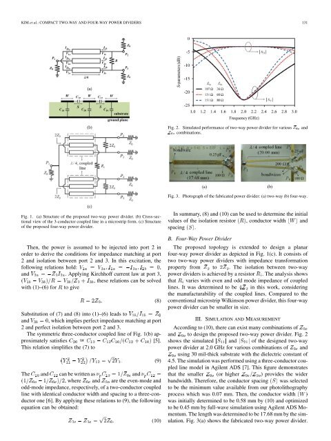
KIM et al.: COMPACT TWO-WAY AND FOUR-WAY POWER DIVIDERS 131Fig. 2. Simulated performance of two-way power divider for various ZZ combinations.<strong>and</strong>Fig. 3.Photograph of the fabricated power divider: (a) two-way (b) four-way.Fig. 1. (a) Structure of the proposed two-way power divider. (b) Cross-sectionalview of the 3-conductor coupled line in a microstrip form. (c) Structureof the proposed four-way power divider.Then, the power is assumed to be injected into port 2 inorder to derive the conditions for impedance matching at port2 <strong>and</strong> isolation between port 2 <strong>and</strong> 3. In this excitation, thefollowing relations hold: ,<strong>and</strong> . Applying Kirchhoff current law at port 3,, these relations can be solvedwith (1)–(6) for to giveSubstitution of (7) <strong>and</strong> (8) into (1)–(6) leads to<strong>and</strong> , which implies perfect impedance matching at port2 <strong>and</strong> perfect isolation between port 2 <strong>and</strong> 3.The symmetric three-conductor coupled line of Fig. 1(b) approximatelysatisfies [5].This relation simplifies the (7) toThe <strong>and</strong> can be written as <strong>and</strong>, where <strong>and</strong> are the even-mode <strong>and</strong>odd-mode impedance, respectively, of a two-conductor coupledline with identical conductor width <strong>and</strong> spacing to a three-conductorone [6]. By applying these relations to (9), the followingequation can be obtained:(8)(9)(10)In summary, (8) <strong>and</strong> (10) can be used to determine the initialvalues of the isolation resistor , conductor width <strong>and</strong>spacing .B. <strong>Four</strong>-<strong>Way</strong> <strong>Power</strong> DividerThe proposed topology is extended to design a planarfour-way power divider as depicted in Fig. 1(c). It consists oftwo two-way power dividers with impedance transformationproperty from to . The isolation between two-waypower dividers is achieved by a resistor . The analysis showsthat varies with even <strong>and</strong> odd mode impedance of coupledlines. It was determined to be in this work, consideringthe manufacturability of the coupled lines. Compared to theconventional microstrip Wilkinson power divider, this four-waypower divider can be smaller in size.III. SIMULATION AND MEASUREMENTAccording to (10), there can exist many combinations of<strong>and</strong> to design the proposed two-way power divider. Fig. 2shows the simulated <strong>and</strong> of the designed two-waypower divider at 2.0 GHz for various combinations of <strong>and</strong>using 30 mil-thick substrate with the dielectric constant of4.5. The simulation was performed using a three-conductor coupledline model in Agilent ADS [7]. This figure demonstratesthat the smaller (or higher ) provides the widerb<strong>and</strong>width. Therefore, the conductor spacing was selectedto be the minimum value available from our photolithographyprocess which was 0.07 mm. Then, the conductor widthwas initially determined to be 0.58 mm by (10) <strong>and</strong> optimizedto be 0.45 mm by full-wave simulation using Agilent ADS Momentum.The length was determined to be 17.68 mm by the simulation.Fig. 3(a) shows the fabricated two-way power divider.