Compact Two-Way and Four-Way Power Dividers ... - IEEE Xplore
Compact Two-Way and Four-Way Power Dividers ... - IEEE Xplore
Compact Two-Way and Four-Way Power Dividers ... - IEEE Xplore
- No tags were found...
Create successful ePaper yourself
Turn your PDF publications into a flip-book with our unique Google optimized e-Paper software.
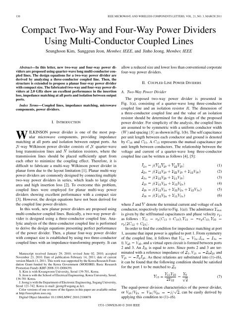
130 <strong>IEEE</strong> MICROWAVE AND WIRELESS COMPONENTS LETTERS, VOL. 21, NO. 3, MARCH 2011<strong>Compact</strong> <strong>Two</strong>-<strong>Way</strong> <strong>and</strong> <strong>Four</strong>-<strong>Way</strong> <strong>Power</strong> <strong>Dividers</strong>Using Multi-Conductor Coupled LinesSeunghoon Kim, Sanggeun Jeon, Member, <strong>IEEE</strong>, <strong>and</strong> Jinho Jeong, Member, <strong>IEEE</strong>Abstract—In this letter, new two-way <strong>and</strong> four-way power dividersare proposed using quarter-wave long multi-conductor coupledlines. The design equations for a two-way power divider arederived by analyzing a three-conductor coupled line. Then, thestructure is extended to propose a planar four-way power dividerwith compact size. The fabricated two-way <strong>and</strong> four-way power dividersat 2.0 GHz show an excellent performance in the insertionloss, impedance matching at all ports <strong>and</strong> isolation between outputports.Index Terms—Coupled lines, impedance matching, microwavecomponents, power dividers.I. INTRODUCTIONWILKINSON power divider is one of the most popularmicrowave components, providing impedancematching at all ports <strong>and</strong> isolation between output ports. An-way Wilkinson power divider consists of quarter-wavelong transmission lines <strong>and</strong> isolation resistors, where thetransmission lines should be placed sufficiently apart fromeach other to minimize the coupling effect. Therefore, it isdifficult to fabricate a multi-way Wilkinson power divider inplanar form due to the layout limitation [1]. Planar multi-waypower dividers are commonly designed by connecting multipletwo-way power dividers in series, which leads to large chiparea <strong>and</strong> high insertion loss [2]. To overcome this problem,coupled lines were employed for planar multi-way powerdividers showing excellent performance with a compact size[3]. However, the design equations have not been derived forthe coupled line power dividers.In this work, new planar power dividers are proposed usingmulti-conductor coupled lines. Basically, a two-way power divideris designed using a three-conductor coupled line. Analyticanalysis of the three-conductor coupled line is performedto derive the design equations presenting perfect performanceof the power divider. Then, a planar four-way power dividerwith compact size is established by using two three-conductorcoupled lines with an impedance-transforming property. It canManuscript received January 29, 2010; revised June 02, 2010; acceptedNovember 23, 2010. Date of publication February 14, 2011; date of currentversion March 11, 2011. This work was supported by the Korea Research FoundationGrant funded by the Korea Government (MOEHRD, Basic ResearchPromotion Fund) (KRF-2008-331-D00439)S. Kim is with Kwangwoon University, Seoul 139-701, Korea.S. Jeon is with the School of Electrical Engineering, Korea University, Seoul,136-701 Korea.J. Jeong is with the Department of Electronic Engineering, Sogang University,Seoul 121-742, Korea (e-mail: jjeong@sogang.ac.kr).Color versions of one or more of the figures in this paper are available onlineat http://ieeexplore.ieee.org.Digital Object Identifier 10.1109/LMWC.2010.2100078allow a reduced size <strong>and</strong> lower loss than conventional corporatefour-way power dividers.II. COUPLED LINE POWER DIVIDERSA. <strong>Two</strong>-<strong>Way</strong> <strong>Power</strong> DividerThe proposed two-way power divider is presented inFig. 1(a), consisting of a quarter-wave long three-conductorcoupled line <strong>and</strong> an isolation resistor . The dimension ofa three-conductor coupled line <strong>and</strong> the value of an isolationresistor should be determined for the design of the proposedpower divider. For simplicity of the analysis, the coupled linesare assumed to be symmetric with a uniform conductor width<strong>and</strong> spacing as shown in Fig. 1(b). The self capacitanceper unit length between each conductor <strong>and</strong> ground is denotedby <strong>and</strong> .A represents the mutual capacitance perunit length between conductors. The relationship between thevoltage <strong>and</strong> current of a quarter-wave long three-conductorcoupled line can be written as follows [4], [5]:(1)(2)(3)(4)(5)(6)where <strong>and</strong> denote the terminal current <strong>and</strong> voltage of eachconductor, respectively (refer to Fig. 1(a)). The admittanceis given by the self/mutual capacitances <strong>and</strong> phase velocity ,as follows :.In order to find the condition for impedance matching at port1, assume that input power is applied to port 1. From symmetryof the coupled line, it follows that, <strong>and</strong> a virtual open circuit is formed between ports2 <strong>and</strong> 3. An is equal to zero. Since ports 2 <strong>and</strong> 3 are terminatedwith a reference impedance of<strong>and</strong>. As these relations are substituted into (1)–(6),it can be found that the following condition should be satisfiedfor the port 1 to be matched toThe equal-power division characteristics of the power divider,or, can be easily derived byapplying this condition to (1)–(6).(7)1531-1309/$26.00 © 2010 <strong>IEEE</strong>
KIM et al.: COMPACT TWO-WAY AND FOUR-WAY POWER DIVIDERS 131Fig. 2. Simulated performance of two-way power divider for various ZZ combinations.<strong>and</strong>Fig. 3.Photograph of the fabricated power divider: (a) two-way (b) four-way.Fig. 1. (a) Structure of the proposed two-way power divider. (b) Cross-sectionalview of the 3-conductor coupled line in a microstrip form. (c) Structureof the proposed four-way power divider.Then, the power is assumed to be injected into port 2 inorder to derive the conditions for impedance matching at port2 <strong>and</strong> isolation between port 2 <strong>and</strong> 3. In this excitation, thefollowing relations hold: ,<strong>and</strong> . Applying Kirchhoff current law at port 3,, these relations can be solvedwith (1)–(6) for to giveSubstitution of (7) <strong>and</strong> (8) into (1)–(6) leads to<strong>and</strong> , which implies perfect impedance matching at port2 <strong>and</strong> perfect isolation between port 2 <strong>and</strong> 3.The symmetric three-conductor coupled line of Fig. 1(b) approximatelysatisfies [5].This relation simplifies the (7) toThe <strong>and</strong> can be written as <strong>and</strong>, where <strong>and</strong> are the even-mode <strong>and</strong>odd-mode impedance, respectively, of a two-conductor coupledline with identical conductor width <strong>and</strong> spacing to a three-conductorone [6]. By applying these relations to (9), the followingequation can be obtained:(8)(9)(10)In summary, (8) <strong>and</strong> (10) can be used to determine the initialvalues of the isolation resistor , conductor width <strong>and</strong>spacing .B. <strong>Four</strong>-<strong>Way</strong> <strong>Power</strong> DividerThe proposed topology is extended to design a planarfour-way power divider as depicted in Fig. 1(c). It consists oftwo two-way power dividers with impedance transformationproperty from to . The isolation between two-waypower dividers is achieved by a resistor . The analysis showsthat varies with even <strong>and</strong> odd mode impedance of coupledlines. It was determined to be in this work, consideringthe manufacturability of the coupled lines. Compared to theconventional microstrip Wilkinson power divider, this four-waypower divider can be smaller in size.III. SIMULATION AND MEASUREMENTAccording to (10), there can exist many combinations of<strong>and</strong> to design the proposed two-way power divider. Fig. 2shows the simulated <strong>and</strong> of the designed two-waypower divider at 2.0 GHz for various combinations of <strong>and</strong>using 30 mil-thick substrate with the dielectric constant of4.5. The simulation was performed using a three-conductor coupledline model in Agilent ADS [7]. This figure demonstratesthat the smaller (or higher ) provides the widerb<strong>and</strong>width. Therefore, the conductor spacing was selectedto be the minimum value available from our photolithographyprocess which was 0.07 mm. Then, the conductor widthwas initially determined to be 0.58 mm by (10) <strong>and</strong> optimizedto be 0.45 mm by full-wave simulation using Agilent ADS Momentum.The length was determined to be 17.68 mm by the simulation.Fig. 3(a) shows the fabricated two-way power divider.
132 <strong>IEEE</strong> MICROWAVE AND WIRELESS COMPONENTS LETTERS, VOL. 21, NO. 3, MARCH 2011velocity between even-mode <strong>and</strong> odd-mode [8]. The fabricatedfour-way power divider is presented in Fig. 3(b) with conductorwidth of 0.28 mm, spacing of 0.07 mm <strong>and</strong> length of 20.00 mm.RF connectors are mounted at each port for the measurement.The measured <strong>and</strong> simulated S-parameters of the two-waypower divider are presented in Fig. 4(a). It shows excellent performancewith the insertion lossof 3.1 dB, returnlossbetter than 20.0 dB <strong>and</strong> isolationbetter than 20.0 dB at 2.0 GHz. In comparison with aconventional Wilkinson power divider, the b<strong>and</strong>width performanceis slightly narrower due to the coupled lines [6]. It can beimproved by using advanced photolithography process allowingsmaller conductor spacing.Fig. 4(b) <strong>and</strong> (c) show the measured S-parameters of thefour-way power divider (simulated ones are omitted for readability).At 2.0 GHz, the insertion loss was measured to be 6.25dB with a variation of dB between the two output ports,implying very low insertion loss. The return loss at all ports<strong>and</strong> isolation between all output ports are better than 20.0 dB,even though the center frequency is shifted to 2.1 GHz due tothe coupling effect between adjacent two coupled lines.IV. CONCLUSIONIn this letter, new two-way <strong>and</strong> four-way power dividerswere presented using multi-conductor coupled lines. The fabricatedpower divider showed the excellent performance such asvery low insertion loss, equal power division, good return loss<strong>and</strong> isolation. The four-way power divider consisting of twotwo-way power dividers can provide lower loss <strong>and</strong> smallersize compared to the conventional corporate four-way powerdivider. This work demonstrates that multi-conductor coupledlines can be applied to planar multi-way power dividers withcompact size <strong>and</strong> low loss.Fig. 4. Simulation <strong>and</strong> measurement result: (a) two-way power divider (b)four-way power divider (insertion <strong>and</strong> return loss) (c) four-way power divider(isolation).A capacitor of 0.25 pF was inserted in parallel with the isolationresistor of 100 , which minimizes the difference of the phaseREFERENCES[1] E. J. Wilkinson, “An N-way power divider,” <strong>IEEE</strong> Trans. Microw.Theory Tech., vol. MTT-8, no. 1, pp. 116–118, Jan. 1960.[2] J. Zhou, K. A. Morris, <strong>and</strong> M. J. Lancaster, “General design ofmultiway multisection power dividers by interconnecting two-waydividers,” <strong>IEEE</strong> Trans. Microw. Theory Tech., vol. 55, no. 10, pp.2208–2215, Oct. 2007.[3] Y.-A. Lai, C.-M. Lin, J.-C. Chiu, C.-H. Lin, <strong>and</strong> Y.-H. Wang, “A compactKa-b<strong>and</strong> planar three-way power divider,” <strong>IEEE</strong> Microw. WirelessCompon. Lett., vol. 17, no. 12, pp. 840–842, Dec. 2007.[4] S. Yamamoto, T. Azakami, <strong>and</strong> K. Itakura, “Coupled strip transmissionline with three center conductors,” <strong>IEEE</strong> Trans. Microw. Theory Tech.,vol. MTT-14, no. 10, pp. 446–461, Oct. 1966.[5] W. P. Ou, “Design equations for an interdigitated directional coupler,”<strong>IEEE</strong> Trans. Microw. Theory Tech., vol. MTT-23, no. 2, pp. 253–255,Feb. 1975.[6] D. M. Pozar, Microwave Engineering. New York: Wiley, 2005.[7] M. Kirschning <strong>and</strong> R. H. Jansen, “Accurate wide-range design equationsfor the frequency-dependent characteristic of parallel coupled microstriplines,” <strong>IEEE</strong> Trans. Microw. Theory Tech., vol. MTT-32, no.1, pp. 83–90, Jan. 1984.[8] R. Mongia, P. Bhartia, <strong>and</strong> I. J. Bahl, RF <strong>and</strong> Microwave Coupled-LineCircuits. Norwood, MA: Artech House, 1999.


