Program Logic Manual - All about the IBM 1130 Computing System
Program Logic Manual - All about the IBM 1130 Computing System
Program Logic Manual - All about the IBM 1130 Computing System

You also want an ePaper? Increase the reach of your titles
YUMPU automatically turns print PDFs into web optimized ePapers that Google loves.
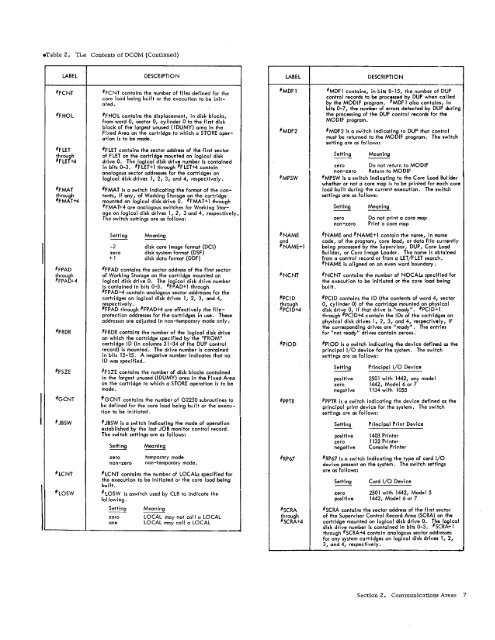
*Table 2. The Contents of DCOM (Continued)LABELDESCRIPTIONLABELDESCRIPTION#FCNT#FHOLOFCNT contains <strong>the</strong> number of files defined for <strong>the</strong>core load being built or <strong>the</strong> execution to be initated.#FHOL contains <strong>the</strong> displacement, in disk blocks,from word 0, sector 0, cylinder 0 to <strong>the</strong> first diskblock of <strong>the</strong> largest unused (1DUMY) area in <strong>the</strong>Fixed Area on <strong>the</strong> cartridge to which a STORE operationis to be made.# FLET #FLET contains <strong>the</strong> sector address of <strong>the</strong> first sectorthroughof F LET on <strong>the</strong> cartridge mounted on logical diskO F LET+4drive 0. The logical disk drive number is containedin bits 0-3. #FLET+1 through O F LET+4 containanalogous sector addresses for <strong>the</strong> cartridges onlogical disk drives 1, 2, 3, and 4, respectively.# FMAT #FMAT is a switch Indicating <strong>the</strong> format of <strong>the</strong> conthroughtents, if any, of Working Storage on <strong>the</strong> cartridge# FMAT+4 mounted on logical disk drive 0. #FMAT+1 through# FMAT+4 are analogous switches for Working Storageon logical disk drives 1, 2, 3 and 4, respectively.The switch settings are as follows:O FPADthroughO FPAD+4Setting Meaning-2 disk core image format (DCI)zero disk system format (DSF)+1 disk data format (DDF)OFPAD contains <strong>the</strong> sector address of <strong>the</strong> first sectorof Working Storage on <strong>the</strong> cartridge mounted onlogical disk drive 0. The logical disk drive numberis contained in bits 0-3. #FPAD+1 through# FPAD+4 contain analogous sector addresses for <strong>the</strong>cartridges on logical disk drives 1, 2, 3, and 4,respectively.# FPAD through #FPAD+4 are effectively <strong>the</strong> fileprotectionaddresses for <strong>the</strong> cartridges in use. Theseaddresses are adjusted in non-temporary mode only.# FRDR #FRDR contains <strong>the</strong> number of <strong>the</strong> logical disk driveon which <strong>the</strong> cartridge specified by <strong>the</strong> "FROM"cartridge ID (in columns 31-34 of <strong>the</strong> DUP controlrecord) is mounted. The drive number is containedin bits 12-15. A negative number indicates that noID was specified.# FSZE #FSZE contains <strong>the</strong> number of disk blocks containedin <strong>the</strong> largest unused (IDUMY) area in <strong>the</strong> Fixed Areaon <strong>the</strong> cartridge to which a STORE operation is to bemade.#GCNT#GCNT contains <strong>the</strong> number of G2250 subroutines tobe defined for <strong>the</strong> core load being built or <strong>the</strong> executionto be initiated.# JBSW #JBSW is a switch indicating <strong>the</strong> mode of operationestablished by <strong>the</strong> last JOB monitor control record.The switch settings are as follows:Setting Meaningzero temporary modenon-zero non-temporary mode.# LCNT #LCNT contains <strong>the</strong> number of LOCALS specified for<strong>the</strong> execution to be initiated or <strong>the</strong> core load beingbuilt.# LOSW #LOSW is aswitch used by CLB to indicate <strong>the</strong>fol lowing.Setting Meaningzero LOCAL may not call a LOCALone LOCAL may call a LOCALO MDF 1#MDF2#MDF1 contains, in bits 8-15, <strong>the</strong> number of DUPcontrol records to be processed by DUP when calledby <strong>the</strong> MODIF program. # MDF1 also contains, inbits 0-7, <strong>the</strong> number of errors detected by DUP during<strong>the</strong> processing of <strong>the</strong> DUP control records for <strong>the</strong>MODIF program.#MDF2 is a switch indicating to DUP that controlmust be returned to <strong>the</strong> MODIF program. The switchsetting are as follows:Setting Meaningzero Do not return to MODIFnon-zero Return to MODIF# MPSW OMPSW is a switch indicating to <strong>the</strong> Core Load Builderwhe<strong>the</strong>r or not a core map is to be printed for each coreload built during <strong>the</strong> current execution. The switchsettings are as follows:Setting MeaningZero Do not print a core mapnon-zero Print a core map# NAME NAME and O NAME+1 contain <strong>the</strong> name, in nameandcode, of <strong>the</strong> program, core load, or data file currently# NAME+1 being processed by <strong>the</strong> Supervisor, DUP, Core LoadBuilder, or Core Image Loader. The name is obtainedfrom a control record or from a LET/FLET search.# NAME is aligned on an even word boundary.# NCNT #NCNT contains <strong>the</strong> number of NOCALs specified for<strong>the</strong> execution to be initiated or <strong>the</strong> core load beingbui It.#PCIDthroughO PCID+4#PCID contains <strong>the</strong> ID (<strong>the</strong> contents of word 4, sector0, cylinder 0) of <strong>the</strong> cartridge mounted on physicaldisk drive 0, if that drive is "ready". #PCID+1through #PCID+4 contain <strong>the</strong> IDs of <strong>the</strong> cartridges onphysical disk drives 1, 2, 3, and 4, respectively, if<strong>the</strong> corresponding drives are "ready". The entriesfor "not ready" drives contain zeroes.# PIOD #PIOD is a switch indicating <strong>the</strong> device defined as <strong>the</strong>principal I/O device for <strong>the</strong> system. The switchsettings are as follows:Setting Principal I/O Devicepositive 2501 with 1442, any modelzero 1442, Model 6 or 7negative 1134 with 1055# PPTR #PPTR is a switch indicating <strong>the</strong> device defined as <strong>the</strong>principal print device for <strong>the</strong> system. The switchsettings are as follows:Setting Principal Print Devicepositive 1403 Printerzero 1132 Printernegative Console Printer# RP67 #RP67 is a switch indicating <strong>the</strong> type of card I/0device present on <strong>the</strong> system. The switch settingsare as follows:Setting Card I/0 Devicezero 2501 with 1442, Model 5positive 1442, Model 6 or 7# SCRA #SCRA contains <strong>the</strong> sector address of <strong>the</strong> first sectorthrough of <strong>the</strong> Supervisor Control Record Area (SCRA) on <strong>the</strong># SCRA+4 cartridge mounted on logical disk drive 0. The logicaldisk drive number is contained in bits 0-3. #SCRA+1through # SCRA+4 contain analogous sector addressesfor any system cartridges on logical disk drives 1, 2,3, and 4, respectively.Section 2. Communications Areas 7