Chapter 6 - Level 2 NVQ and Technical ... - Pearson Schools
Chapter 6 - Level 2 NVQ and Technical ... - Pearson Schools
Chapter 6 - Level 2 NVQ and Technical ... - Pearson Schools

Create successful ePaper yourself
Turn your PDF publications into a flip-book with our unique Google optimized e-Paper software.
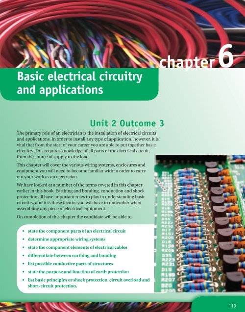
Basic electrical circuitry<br />
<strong>and</strong> applications<br />
Unit 2 Outcome 3<br />
The primary role of an electrician is the installation of electrical circuits<br />
<strong>and</strong> applications. In order to install any type of application, however, it is<br />
vital that from the start of your career you are able to put together basic<br />
circuitry. This requires knowledge of all parts of the electrical circuit,<br />
from the source of supply to the load.<br />
This chapter will cover the various wiring systems, enclosures <strong>and</strong><br />
equipment you will need to become familiar with in order to carry<br />
out your work as an electrician.<br />
We have looked at a number of the terms covered in this chapter<br />
earlier in this book. Earthing <strong>and</strong> bonding, conduction <strong>and</strong> shock<br />
protection all have important roles to play in underst<strong>and</strong>ing basic<br />
circuitry, <strong>and</strong> it is these factors you will have to remember when<br />
assembling any piece of electrical equipment.<br />
On completion of this chapter the c<strong>and</strong>idate will be able to:<br />
•<br />
•<br />
•<br />
•<br />
•<br />
•<br />
•<br />
state the component parts of an electrical circuit<br />
determine appropriate wiring systems<br />
state the component elements of electrical cables<br />
differentiate between earthing <strong>and</strong> bonding<br />
list possible conductive parts of structures<br />
state the purpose <strong>and</strong> function of earth protection<br />
list basic principles or shock protection, circuit overload <strong>and</strong><br />
short-circuit protection.<br />
chapter6<br />
119
<strong>NVQ</strong>2 Electrical Installations<br />
Remember<br />
If a d.c. supply requires a<br />
higher voltage, a series<br />
of batteries can be used<br />
rather than just one<br />
Remember<br />
A transformer can be<br />
used for an alternative<br />
voltage<br />
Did you<br />
know?<br />
The voltage will change<br />
depending on the<br />
intended use for the<br />
cable. A bell circuit which<br />
is to be supplied at 6 V<br />
will require considerably<br />
less insulation than a<br />
cable used to supply a<br />
heater at 230 V<br />
120<br />
The component parts of an electrical circuit<br />
On completion of this topic area the c<strong>and</strong>idate will be able to state the component<br />
parts of an electric circuit.<br />
BS 7671 defines a circuit as ‘an assembly of electrical equipment ��������supplied<br />
from<br />
������ ���� ������ � �������<br />
�<br />
the same origin <strong>and</strong> protected against overcurrent by the same protective devices’.<br />
So what does make up the circuit?<br />
Source of supply<br />
Often a circuit is thought of as being the load <strong>and</strong> the conductors supplying the load.<br />
However in reality they are only part of the circuit. In order for current to flow two<br />
conditions have to be met.<br />
1.<br />
There has to be a potential difference applied across the circuit (voltage).<br />
��������<br />
2. There has to be a complete circuit (circle) for current to flow around.<br />
The source of supply can be a.c. or d.c. If a d.c. supply is required, then this is derived<br />
from a battery. For an a.c. supply, either an a.c. generator or a d.c. generator with<br />
electrical components to rectify the supply, can be used.<br />
An a.c. supply can be obtained directly from the mains. Single phase 230 V or three<br />
phase 400 V are those generally available in the UK.<br />
The size <strong>and</strong> type of voltage required for the supply is determined by the load<br />
equipment to be used. All electrical equipment will have a plate attached to it<br />
indicating its safe working voltage.<br />
Circuit conductors (cable)<br />
The circuit conductors are those parts of the circuit which the current passes through.<br />
These are the cables. Cables have �������� two components to them. One is the conductor<br />
������ ���� ������ � �������<br />
�<br />
itself. This is usually made of copper. The other part is insulation, usually made from<br />
PVC, which forms a sheath around the conductor. The insulation is required to:<br />
●<br />
●<br />
������ ���� ������ � �������<br />
�<br />
prevent the conductors touching together; this could short the circuit <strong>and</strong><br />
preventing it from working<br />
prevent users of the circuit from coming into contact with the conductors <strong>and</strong><br />
receiving an electric shock.<br />
The type of insulation required is determined by the voltage which is to be applied to<br />
the cable.<br />
Cables come as either single or multicore cables. Both have an overall sheath to keep<br />
all the associated cables together <strong>and</strong> to provide a minimal degree of mechanical<br />
protection. Appendix 4 of BS 7671 gives details on the sizes <strong>and</strong> types of cables<br />
available to us. We will be looking in more detail at types of cable later in this chapter.
The size of conductor used in a circuit is important <strong>and</strong> needs to be calculated<br />
accurately. We need to be sure that the conductor is large enough to carry the current<br />
produced by the load <strong>and</strong> to be sure that the load receives sufficient voltage for it to<br />
work safely.<br />
Circuit protection<br />
Every circuit requires protection if, in the event of a fault, damage is to be avoided.<br />
The inclusion into the circuit of a suitably rated fuse or protective device, such as a<br />
miniature circuit breaker (MCB) will protect both the load, <strong>and</strong> the cables supplying<br />
the load, from the heat damage associated with large fault currents.<br />
Protective devices are used to provide a circuit with overload protection, short-circuit<br />
protection <strong>and</strong> shock protection. We will be looking at these in greater detail later in<br />
this chapter.<br />
The protective device, or fuse, is deliberately designed to be a ‘weak link’ in a circuit.<br />
When current increases to a level where damage can be sustained, the fuse operates<br />
<strong>and</strong> automatically interrupts the supply to the circuit. As the fuse is a part of the<br />
circuit, once it is ‘broken’ it also breaks the flow within the circuit, ending the supply.<br />
Circuits supplied at voltages below 50 V may be required to have circuit protection for<br />
functional reasons. Circuits supplied at 50 V <strong>and</strong> above are required to have circuit<br />
protection that complies with the requirements of BS 7671. For example, low voltage<br />
circuits (above 50 volts, but not exceeding 1000 volts) supplying socket outlets must<br />
automatically disconnect in the event of an earth fault within 0.4 seconds.<br />
Protective device types include:<br />
●<br />
●<br />
●<br />
Rewirable fuses to BS 3036<br />
Cartridge fuses to BS 1361<br />
Cartridge fuses to BS 88<br />
Circuit control<br />
MCBs to BS EN 60898<br />
RCBOs to BS EN 61009.<br />
It is vital that any circuit, no matter its level of complexity, can be controlled. This<br />
could be either:<br />
●<br />
●<br />
●<br />
a simple switch, allowing us to turn the circuit on or off<br />
a time switch, which activates the circuit at certain times<br />
a float switch, which controls the water levels in a pump.<br />
The last example is known as functional switching.<br />
Isolation is the ability to remove the supply from all the live conductors, such as at<br />
the mains switch, to a complete installation. Emergency switching is another area of<br />
control that is required for some circuits. This allows us to press one button <strong>and</strong> turn<br />
off the main supply to a series of equipment, in the event of danger.<br />
●<br />
●<br />
<strong>Chapter</strong> 6 Basic electrical circuitry <strong>and</strong> applications<br />
Remember<br />
BS 7671 Appendix 4 has<br />
tables indicating the<br />
current carrying capacity<br />
<strong>and</strong> volt drop for given<br />
sizes <strong>and</strong> types of cable<br />
Did you<br />
know?<br />
Circuits supplying<br />
fixed equipment, such<br />
as lighting, are only<br />
required to disconnect<br />
within 5 seconds<br />
Did you<br />
know?<br />
RCBO st<strong>and</strong>s for<br />
residual current device<br />
(RCD) with overl<strong>and</strong><br />
protection, combining<br />
the capabilities of RCD<br />
<strong>and</strong> MCB<br />
121
<strong>NVQ</strong>2 Electrical Installations<br />
122<br />
Load<br />
The load refers to the item that requires the supply in order to function. For example,<br />
this might mean the lights in a circuit, a heater, a motor to drive a pump or any item<br />
of equipment (or combinations of these) that require an electrical supply in order for<br />
them to work.<br />
Electrical loads are rated in watts or kilowatts (W <strong>and</strong> kW). The size of the load is<br />
generally stamped on the equipment or marked on a nameplate. This can contain the:<br />
●<br />
●<br />
rating in watts<br />
supply voltage<br />
●<br />
●<br />
frequency of the supply<br />
full load current.<br />
If this information is not available on a nameplate, then it would be necessary to<br />
refer to the manufacturer’s literature to establish the requirements of the load.<br />
Determine appropriate wiring systems,<br />
enclosures <strong>and</strong> equipment<br />
On completion of this topic area the c<strong>and</strong>idate will be able to determine appropriate<br />
wiring systems, enclosures <strong>and</strong> equipment.<br />
The role of BS 7671<br />
<strong>Chapter</strong> 13 Part 1 of BS 7671 requires that all electrical installations shall be designed<br />
to provide for the protection of persons, livestock <strong>and</strong> property <strong>and</strong> the proper<br />
functioning of the electrical installation for the intended use.<br />
In order to do this BS 7671 requires us to determine the characteristics of the<br />
available supply. This can be done by calculation, measurement, enquiry or<br />
inspection of existing supplies. The characteristics that need to be determined are:<br />
●<br />
●<br />
●<br />
●<br />
●<br />
●<br />
●<br />
●<br />
●<br />
●<br />
the nature of the current – either a.c. or d.c.<br />
the number of conductors<br />
voltage<br />
frequency<br />
maximum current allowed<br />
prospective short-circuit current<br />
earth loop impedance<br />
nature <strong>and</strong> size of the load<br />
number <strong>and</strong> type of circuits required<br />
the location <strong>and</strong> any special conditions that may apply. This should take into<br />
account the nature of the location <strong>and</strong> structure that will support the wiring<br />
system <strong>and</strong> the accessibility of the wiring to people <strong>and</strong> livestock.
Insulation colours<br />
To identify cables the insulation is coloured in accordance with BS 7671, Table 51.<br />
Table 51 Identification of conductors<br />
Function Colour<br />
Protective conductors Green <strong>and</strong> yellow<br />
Functional earthing conductor Cream<br />
a.c. power circuit (1)<br />
Phase of single-phase circuit<br />
Neutral of single- or three-phase circuit<br />
Phase 1 of three-phase a.c. circuit<br />
Phase 2 of three-phase a.c. circuit<br />
Phase 3 of three-phase a.c. circuit<br />
Two-wire unearthed d.c. power circuit<br />
Positive of two-wire circuit<br />
Negative of two-wire circuit<br />
Two-wire earthed d.c. power circuit<br />
Positive (of negative earthed) circuit<br />
Negative (of negative earthed) circuit<br />
Positive (of positive earthed) circuit<br />
Negative (of positive earthed) circuit<br />
Three-wire d.c. power circuit<br />
Outer positive of two-wire circuit derived from three-wire system<br />
Outer negative of two-wire circuit derived from three-wire system<br />
Positive of three-wire circuit<br />
Mid-wire of three-wire circuit (2)<br />
Negative of three-wire circuit<br />
Control circuits, ELV <strong>and</strong> other applications<br />
Phase conductor<br />
<strong>Chapter</strong> 6 Basic electrical circuitry <strong>and</strong> applications<br />
Brown<br />
Blue<br />
Brown<br />
Black<br />
Grey<br />
Brown<br />
Grey<br />
Brown<br />
Blue<br />
Blue<br />
Grey<br />
Brown<br />
Grey<br />
Brown<br />
Blue<br />
Grey<br />
Neutral or mid-wire (3) Blue<br />
NOTES<br />
(1) Power circuits include lighting circuits.<br />
(2) Only the middle wire of three-wire circuits may be earthed.<br />
(3) An earthed PELV conductor is blue.<br />
Table 6.01 To identify cable insulation in accordance with BS 7671<br />
Brown, black, red,<br />
orange, yellow,<br />
violet, grey, white,<br />
pink or turquoise<br />
You will come across conductors with these colours of insulation for many years to<br />
come, but only in existing installations. From 1 April 2004, the colours of conductor<br />
insulation for new installations changed.<br />
123
<strong>NVQ</strong>2 Electrical Installations<br />
Safety tip<br />
Great care must be<br />
taken when installing<br />
<strong>and</strong> connecting cables,<br />
especially where old<br />
<strong>and</strong> new cable colours<br />
are present in the same<br />
building<br />
Did you<br />
know?<br />
Reference numbers in<br />
brackets here are used<br />
by manufacturers to<br />
define cable types<br />
124<br />
Conductor Old colour<br />
Phase Red<br />
Neutral Black<br />
Protective conductor Green <strong>and</strong> yellow<br />
Phase one Red<br />
Phase two Yellow<br />
Phase three Blue<br />
Neutral Black<br />
Protective conductor Green <strong>and</strong> yellow<br />
Table 6.02 Old conductor insulation colours<br />
Single- or three-phase power supplies<br />
In the UK the size of supply brought into most households is 100 amps single phase,<br />
50 Hertz. Should the assumed current dem<strong>and</strong> of an installation exceed 100 amps,<br />
then a three-phase supply is required. However the selection of a three-phase<br />
supply can also simply be down to the load, i.e. a requirement to install three-phase<br />
machines, motors, pumps etc.<br />
Appendix 1 of the On Site Guide gives details of the requirements for calculating<br />
dem<strong>and</strong> <strong>and</strong> diversity for installations. You will deal with single- <strong>and</strong> three-phase<br />
supplies in greater detail in chapter 11.<br />
Switching of lighting circuits<br />
There are numerous switching arrangements that make up a lighting circuit. This<br />
section will look at the most common ones. It would not be practical to look at all the<br />
possible combinations, as there are simply far too many.<br />
Cabling Switching arrangements<br />
Wiring in conduit <strong>and</strong>/or trunking<br />
Wiring using multicore/composite cables.<br />
Table 6.03 Switching arrangements<br />
��������<br />
������ ���� ������ � �������<br />
�<br />
Wiring in conduit <strong>and</strong> trunking<br />
Two-way switching<br />
Intermediate switching<br />
One-way switching<br />
��������<br />
������ ���� ������ � �������<br />
�<br />
Wiring in this type of installation is carried out using PVC single-core insulated<br />
cables (Ref. 6491 X). This code number is a manufacturer’s code used to denote<br />
different types of cable. The phase (live) conductor is taken directly to the first<br />
switch <strong>and</strong> looped from switch to switch for all the remaining lights connected to
that particular circuit. The neutral conductor is taken directly to the lighting outlet<br />
(luminaires) <strong>and</strong> looped between all the remaining luminaires on that circuit. The<br />
switch wire is run between the switch <strong>and</strong> the luminaire it controls.<br />
Wiring using multicore/composite cables<br />
This type of cable is normally a sheathed multicore twin <strong>and</strong> earth or three cores <strong>and</strong><br />
earth (two-way <strong>and</strong> intermediate circuits only) (Ref. 6242Y <strong>and</strong> 6243Y respectively). A<br />
‘loop in’ or ‘joint box’ method may be employed with this type of installation. In many<br />
instances a loop-in system is specified as there are no joint boxes installed <strong>and</strong> all<br />
terminations are readily accessible at the switches <strong>and</strong> ceiling roses.<br />
With a joint box system normally only one cable is run to each wiring outlet. Where<br />
such joint boxes are installed beneath floors they should be accessible by leaving a<br />
screwed trap in the floorboard directly above the joint box. All conductors should be<br />
correctly colour identified.<br />
On a composite cable installation, where the conductors other than brown are used<br />
as a phase conductor, they should be fitted with a brown sleeve at their terminations.<br />
All conductors must be contained within a non-combustible enclosure at wiring<br />
outlets (i.e. the sheathing of the cable must be taken into the wiring accessory).<br />
Throughout the lighting installation a circuit protective conductor (cpc) must be<br />
installed <strong>and</strong> terminated at a suitable earthing terminal in the accessory/box.<br />
Where an earthing terminal may not be fitted in a PVC switch pattress, the cpc may<br />
be terminated in a connector. Where the sheathing is removed from a composite<br />
cable the cpc must be fitted with an insulating sleeve (green <strong>and</strong> yellow); this<br />
provides equivalent insulation to that provided by the insulation of a single-core<br />
non-sheathed cable of appropriate size complying with BS 6004 or BS 7211.<br />
One-way switching<br />
The most basic circuit possible is the one-way switch controlling one light, as shown<br />
in Figure 6.01. In this system, one terminal of the one-way switch receives the<br />
switch feed; the switch wire leaves from the other terminal <strong>and</strong> goes directly to the<br />
luminaire (a). Once operated, the switch contact is held in place mechanically <strong>and</strong><br />
therefore the electricity is continually flowing through to the light (b).<br />
(a)<br />
In other words, we supply the switch feed terminal, point (A).<br />
Operate the switch <strong>and</strong> it comes out at the switch wire terminal, point (B).<br />
Figures 6.02 to 6.04 show the full circuit when wired using single-core cables,<br />
which would be run in either conduit or trunking.<br />
Using the old cable colours again, Figure 6.02 now shows a second light point fed<br />
from the same switch wire. This means that the second light is now wired in parallel<br />
<strong>Chapter</strong> 6 Basic electrical circuitry <strong>and</strong> applications<br />
(b)<br />
A<br />
Remember<br />
Red sleeving changes to<br />
brown sleeving<br />
Remember<br />
Cables supplying<br />
switches of any circuit<br />
<strong>and</strong> the cables feeding<br />
away from the switch to<br />
the light are identified.<br />
The cable from the<br />
distribution board to<br />
the switch is called the<br />
switch feed, <strong>and</strong> the<br />
cable from the switch<br />
to the light is called the<br />
switch wire<br />
B<br />
Figure 6.01 One-way switching<br />
Find out<br />
Find out what is pattress<br />
125
<strong>NVQ</strong>2 Electrical Installations<br />
126<br />
Neutral<br />
Phase<br />
cpc<br />
with the first light.<br />
switch feed switch wire<br />
Figure 6.02 One-way switching for wiring with<br />
single-core cables (old cable colours)<br />
Neutral<br />
Phase<br />
cpc<br />
switch feed switch wire<br />
3-plate<br />
ceiling<br />
rose<br />
Two-way switching<br />
Neutral<br />
Phase<br />
cpc<br />
A B<br />
C<br />
B<br />
C<br />
switch feed switch wire<br />
Figure 6.03 One-way switching for wiring with<br />
single-core cables (new cable colours)<br />
3-plate<br />
ceiling<br />
rose<br />
Figure 6.04 Extra lighting<br />
fed from the same switch,<br />
wired in parallel (new<br />
cable colours)<br />
Sometimes we need to switch a light on, or off, from more than one location, e.g.<br />
at opposite ends of a long corridor. When this is required, a different switching<br />
arrangement must be used, the most common being the two-way switch circuit. In<br />
this type of circuit, the switch feed is feeding one two-way switch, <strong>and</strong> the switch<br />
wire goes from the other two-way switch to the luminaire(s). Two wires known as<br />
‘strappers’ then link the two switches together. In other words:<br />
we supply the switch feed terminal, point (A).<br />
However, depending on the switch contact position, the electricity can come out<br />
on either terminal B or terminal C. In the following diagram it is shown energising<br />
terminal B.<br />
3-plate<br />
ceiling<br />
rose
If we now operated the switch, the contact would move across to energise terminal C.<br />
Please note that actual switch terminals are not marked in this way.<br />
Switching of lighting circuits<br />
By connecting together the two two-way switches we now have the ability at each<br />
switch to either energise the switch wire going to the light or to de-energise it (this is<br />
why this system is ideal for controlling lighting on corridors or staircases). In the first<br />
diagram below, the luminaire is off.<br />
Neutral<br />
cpc<br />
Phase<br />
switch<br />
feed<br />
(b) Old cable colours<br />
L 1<br />
strappers<br />
C C<br />
L 2<br />
Figure 6.05 Full circuit wired with single-core cable. Old <strong>and</strong> new colours<br />
L 1<br />
L C<br />
C<br />
N<br />
L 2<br />
However, operate the second switch <strong>and</strong> we energise the common terminal (C) <strong>and</strong><br />
the luminaire will now come on.<br />
L 1<br />
L 1<br />
L 2<br />
L 1<br />
B<br />
C<br />
off<br />
L C<br />
C<br />
N<br />
L 2<br />
Figure 6.05 shows the full circuit when wired using single-core cable in conduit<br />
or trunking.<br />
Neutral<br />
cpc<br />
Phase<br />
switch<br />
feed<br />
(a) New cable colours<br />
L 1<br />
L 2<br />
L 2<br />
on<br />
strappers<br />
C C<br />
L 1<br />
L 2<br />
L 1<br />
L 2<br />
<strong>Chapter</strong> 6 Basic electrical circuitry <strong>and</strong> applications<br />
switch<br />
wire<br />
switch<br />
wire<br />
127
<strong>NVQ</strong>2 Electrical Installations<br />
128<br />
We can also use two-way switches for other purposes. Figure 6.06 shows one two-way<br />
switch to control two indicator lamps. This sort of system is frequently used as an<br />
entry system outside offices or dark rooms, where the two lamps can be marked, for<br />
example as ‘available’ <strong>and</strong> ‘busy’.<br />
busy<br />
L N<br />
available<br />
Figure 6.06 Two-way switch controlling<br />
two lamps<br />
Intermediate switching<br />
If more than two switch locations are required, e.g. in a long corridor with other<br />
corridors coming off it, then intermediate switches must be used. The intermediate<br />
switches are wired in the ‘strappers’ between the two-way switches.<br />
The action of the intermediate switch is to cross-connect the ‘strapping’ wires. This<br />
gives us the ability to route a supply to any terminal depending upon the switch<br />
contact positions.<br />
When we operate the switch into position two, the switch contacts cross over<br />
(Figure 6.07).<br />
(a) Position one (b) Position two<br />
Figure 6.07<br />
L 1<br />
L 1<br />
A B<br />
L 2<br />
L 2<br />
A<br />
L 1<br />
L 2<br />
This means that a signal sent into terminal A can always be directed on to either<br />
terminal B or terminal C as required.<br />
Ignoring terminal markings, Figure 6.08 shows an arrangement where the switch wire<br />
is de-energised <strong>and</strong> therefore the luminaire is off.<br />
Figure 6.08<br />
L 1<br />
A B<br />
L 1<br />
C C<br />
L 2<br />
L 2<br />
C<br />
L 1<br />
L 2<br />
L 1<br />
L 2<br />
L 1<br />
L 2<br />
C
However, by operating the intermediate switch, we can route the switch feed<br />
along another section of the ‘strappers’ <strong>and</strong> energise the switch wire terminal, <strong>and</strong><br />
therefore the luminaire will come on, as shown in Figure 6.09.<br />
Figure 6.09<br />
To use the example of a long hotel main corridor with other minor corridors coming<br />
off it, if we have an intermediate switch at each junction with the main corridor,<br />
anyone joining or leaving the main corridor now has the ability to switch luminaires<br />
on or off.<br />
Figure 6.10 shows the full circuit in the new colours, when wired using single-core<br />
cable in conduit or trunking.<br />
Neutral<br />
cpc<br />
Phase<br />
L 1<br />
A B<br />
L 1<br />
C C<br />
L 2<br />
L 2<br />
Figure 6.10 New cable colours<br />
Note: in this diagram the light will be off.<br />
Wiring with multicore cables<br />
C<br />
L 1<br />
L 2<br />
L 1<br />
L 1<br />
L 2<br />
<strong>Chapter</strong> 6 Basic electrical circuitry <strong>and</strong> applications<br />
C C<br />
L 2<br />
Multicore cables (commonly referred to as twin <strong>and</strong> earth) are basically a threecore<br />
cable consisting of a phase, neutral <strong>and</strong> earth conductor. Both the phase <strong>and</strong><br />
neutral conductors consist of copper conductors insulated with coloured insulation<br />
(see Figure 6.11 <strong>and</strong> 6.12), the earth being a non-insulated bare copper conductor<br />
s<strong>and</strong>wiched in between the phase <strong>and</strong> neutral. In the old colours, the correct use<br />
of this cable type would be to use two red conductors (switch feed <strong>and</strong> switch wire)<br />
L 1<br />
L 1<br />
L 2<br />
L 2<br />
L 1<br />
L 2<br />
Remember<br />
Any number of<br />
intermediate switches<br />
may be used between<br />
two-way switches <strong>and</strong><br />
they are all wired into<br />
the ‘strappers’. In other<br />
words, an intermediate<br />
switch has two positions<br />
129
<strong>NVQ</strong>2 Electrical Installations<br />
130<br />
from switch locations up to luminaires. However, for ease, it was common practice<br />
for many to use a cable containing red <strong>and</strong> black conductors.<br />
Neutral<br />
Phase<br />
cpc<br />
Figure 6.11 Old cable colours<br />
Neutral<br />
Phase<br />
cpc<br />
Figure 6.12 New cable colours<br />
This means that the black conductor should be sleeved at both ends to indicate that<br />
it is a ‘live’ conductor. (Please be aware that many did not sleeve the conductors <strong>and</strong><br />
therefore a luminaire connected across two black conductors is actually connected to<br />
a switch wire <strong>and</strong> a neutral.)<br />
The outer white or grey covering is the sheath, <strong>and</strong> its main purpose is to prevent<br />
light mechanical damage of the insulation of the conductors.<br />
This cable is often used for wiring domestic <strong>and</strong> commercial lighting circuits, <strong>and</strong> you<br />
would normally use 1.5mm 2 cable. Using this type of cable instead of singles is slightly<br />
more complicated because you are restricted as to where you plan your runs, i.e. in<br />
the old colours the cable will always consist of a red, black <strong>and</strong> earth conductor.<br />
Two-way switching <strong>and</strong> conversion circuit<br />
red sleeving<br />
is used to<br />
identify that the<br />
cable is a phase<br />
conductor<br />
brown sleeving<br />
is used to<br />
identify that the<br />
cable is a phase<br />
conductor<br />
This method of switching using multicore cables requires the use of four-core cable.<br />
This is a cable that has three coloured <strong>and</strong> insulated conductors <strong>and</strong> a bare earth<br />
conductor. The three coloured conductors are in the old colours, coloured red,<br />
yellow, <strong>and</strong> blue. This type of cable is normally only stocked in 1.5mm <strong>and</strong> used in<br />
a lighting circuit where its application is for switching that requires more than one<br />
switch position, i.e. two-way <strong>and</strong> intermediate switching.<br />
It is also used for converting an existing one-way switching arrangement into a two-way<br />
switching arrangement. The first step in this process is to replace the existing one-way<br />
switch with a two-way switch. This would then be connected as shown in Figure 6.13.
Neutral<br />
Phase<br />
cpc<br />
replace the existing<br />
one-way switch with<br />
a two-way switch<br />
Figure 6.13 Conversion of one-way<br />
lighting into two-way switching<br />
The next step is to install the multicore cable between this location <strong>and</strong> the new<br />
two-way switch location <strong>and</strong> complete the circuit connections as in Figure 6.14.<br />
Note: In Figure 6.14 the light will be off.<br />
Intermediate switching<br />
Neutral<br />
Phase<br />
Figure 6.15 illustrates an intermediate lighting circuit using multicore cables.<br />
Neutral<br />
Phase<br />
Note: In Figure 6.15 the light will be on.<br />
Wiring using a junction/joint box<br />
cpc<br />
new two-way switching<br />
This method of wiring is considered somewhat old-fashioned, as it has now been<br />
superseded by the loop-in method. However, that is not to say that you will not come<br />
across this method in the millions of households in the country that have a junction<br />
box method installed. Care should be taken when wiring junction boxes, <strong>and</strong> the<br />
following precautions should be observed:<br />
●<br />
●<br />
cpc<br />
C<br />
L1<br />
L2<br />
two-way switch intermediate switch two-way switch<br />
Figure 6.15 Intermediate switching<br />
L1<br />
L2<br />
L1<br />
L2<br />
L2<br />
L1<br />
Figure 6.14 Conversion of one-way lighting into<br />
two-way switching<br />
C<br />
the protective outer sheath should be taken inside the junction box entries to a<br />
minimum of 10mm<br />
where terminations are made into a connector, only sufficient insulation should<br />
be removed to make the termination<br />
<strong>Chapter</strong> 6 Basic electrical circuitry <strong>and</strong> applications<br />
131
<strong>NVQ</strong>2 Electrical Installations<br />
132<br />
●<br />
●<br />
●<br />
●<br />
sufficient slack should be left inside the joint box to prevent excess tension on<br />
conductors<br />
cables should be inserted so that they are not crossing; they should be neat <strong>and</strong><br />
fitted so that the lid fits without causing damage<br />
correct size joint boxes should be used<br />
joint boxes should be secured to a platform fitted between the floor <strong>and</strong> ceiling joists.<br />
Phase<br />
Neutral<br />
cpc<br />
switch<br />
switch feed switch wire<br />
Joint box<br />
Neutral<br />
Figure 6.16 illustrates the control of one light via a one-way switch using this method.<br />
Rings, radials <strong>and</strong> spurs<br />
Before the early 1950s different types <strong>and</strong> sizes of socket outlet <strong>and</strong> plug were in use<br />
in domestic premises, which was very annoying <strong>and</strong> inconvenient! In 1947, 5 A <strong>and</strong><br />
15 A socket outlets were deemed obsolete, <strong>and</strong> agreement was reached on a st<strong>and</strong>ard<br />
13 A socket outlet with a fused plug, to BS 1363. In this section we will be looking at<br />
the st<strong>and</strong>ard power-circuit arrangements found in domestic premises. In particular<br />
the following will be investigated:<br />
●<br />
●<br />
●<br />
ring circuits<br />
Figure 6.16 One-way switch using a joint box<br />
permanently connected equipment<br />
non-fused spurs<br />
Ring circuits<br />
●<br />
●<br />
fused spurs<br />
radial circuits.<br />
In this system the phase, neutral <strong>and</strong> circuit protective conductors are connected<br />
to their respective terminals at the consumer unit, looped into each socket outlet<br />
in turn <strong>and</strong> then returned to their respective terminals in the consumer unit, thus<br />
forming a ring. Each socket outlet has two connections back to the mains supply.<br />
Lamp
The requirements for a st<strong>and</strong>ard domestic ring circuit are as shown in the bullet<br />
points below. An unlimited number of socket outlets may be installed provided the<br />
following points are taken into account.<br />
●<br />
●<br />
●<br />
●<br />
●<br />
Each socket outlet of twin or multiple sockets is to be regarded as one socket outlet.<br />
The floor area served by a single 30 A or 32 A ring final circuit must not exceed<br />
100m 2 in domestic installations.<br />
Consideration must be given to the loading of the ring main, especially in kitchens<br />
<strong>and</strong> utility rooms, which may require separate circuit(s).<br />
When more than one ring circuit is installed in the same premises, the socket<br />
outlets installed should be reasonably shared among the ring circuits so that the<br />
assessed load is balanced.<br />
Immersion heaters, storage vessels in excess of 15 litres capacity or permanently<br />
connected heating appliances forming part of a comprehensive space-heating<br />
installation, are supplied by their own separate circuit.<br />
A typical domestic ring circuit is shown in Figure 6.17.<br />
cable size not<br />
less than the<br />
ring cable<br />
non-fused spur<br />
ring conductor<br />
rating not less than<br />
0.67 times fuse rating<br />
Permanently connected equipment<br />
cable size not less<br />
than ring cable<br />
fuse to suit<br />
size of load<br />
<strong>Chapter</strong> 6 Basic electrical circuitry <strong>and</strong> applications<br />
fused spur<br />
Permanently connected equipment should be locally protected by a fuse which does<br />
not exceed 13 A <strong>and</strong> be controlled by a switch complying with BS 7671 chapter 46, or<br />
be protected by a circuit breaker not exceeding 16 A rating.<br />
stationary appliance<br />
P<br />
N<br />
Figure 6.17 Domestic ring<br />
circuit with spurs<br />
133<br />
E
<strong>NVQ</strong>2 Electrical Installations<br />
ring<br />
circuit<br />
ring<br />
circuit<br />
134<br />
ring<br />
circuit<br />
ring<br />
circuit<br />
single-socket outlet<br />
double-socket outlet<br />
Figure 6.18 Non-fused spurs<br />
fused connection unit with switch<br />
appliance<br />
fused connection unit (not exceeding 13 A)<br />
Remember<br />
The cable sizes shown<br />
are nominal, <strong>and</strong> if<br />
derating factors apply<br />
e.g. grouping or ambient<br />
temperature, these<br />
sizes may need to be<br />
increased. In practice this<br />
would mean that a 30 A<br />
or 32 A circuit breaker or<br />
fuse would be used as an<br />
overcurrent protection<br />
device <strong>and</strong> the circuit<br />
cable would be selected<br />
accordingly as required<br />
by Regulation 433-02-04<br />
Figure 6.19 Fused spurs<br />
appliance<br />
Radial circuits<br />
Non-fused spurs<br />
Spurs may be installed on a ring circuit. These may be fused, but it is<br />
more common to install non-fused spurs connected to a circuit at<br />
the terminals of socket outlets, at junction boxes, or at the origin of<br />
the circuit in the distribution board. A non-fused spur may supply<br />
only one single or one twin-socket outlet or one item of permanently<br />
connected equipment. The total number of non-fused spurs should<br />
not exceed the total number of socket outlets <strong>and</strong> items of fixed<br />
equipment connected directly to the ring circuit. The size of conductor<br />
for a non-fused spur must be the same as the size of conductor used<br />
on the ring circuit.<br />
Fused spurs<br />
A fused spur is connected to a circuit through a fused connection<br />
unit. The fuse incorporated should be related to the current carrying<br />
capacity of the cable used for the spur but should not exceed 13 A.<br />
When sockets are wired from a fused spur the minimum size of the<br />
conductor is 1.5mm2 for rubber- or PVC-insulated cables with copper<br />
conductors <strong>and</strong> 1mm2 ��������<br />
������ ���� ������ � �������<br />
�<br />
for mineral-insulated cables with copper<br />
conductors. The total number of fused spurs is unlimited.<br />
In a radial circuit the conductors do not form a loop but finish at the last outlet. As<br />
with the ring circuit, the number of outlets in any circuit is unlimited in a floor area<br />
up to the maximum allowed. In each case this will be determined by the estimated<br />
load <strong>and</strong> shock protection constraints.<br />
A2 Radial circuit<br />
The current rating of the cables is determined by the rating of the overcurrent<br />
protection device, i.e. 30 A or 32 A cartridge fuse or MCB. This means that copperconductor<br />
PVC cables of not less than 4mm 2 , or copper-conductor mineral-insulated<br />
cables of not less than 2.5mm 2 , may be used, <strong>and</strong> the floor area served may not<br />
exceed 75m 2 . See Figure 6.20 <strong>and</strong> Table 6.04.<br />
floor area<br />
maximum 75 m 2<br />
Figure 6.20 A2 radial circuit<br />
4 mm2 30 A/32 A
floor area<br />
maximum 50 m 2<br />
Figure 6.21 A3 radial circuit<br />
Type of<br />
circuit<br />
1 2<br />
Rating A<br />
2.5 mm2 20 A<br />
Overcurrent protection<br />
device<br />
3<br />
Rating A<br />
A3 Radial circuit<br />
<strong>Chapter</strong> 6 Basic electrical circuitry <strong>and</strong> applications<br />
In domestic premises this circuit<br />
is wired in 2.5mm 2 copper cable<br />
<strong>and</strong> protected by a 20A device. The<br />
floor area is limited to 50m 2 ; in this<br />
area any number of socket outlets<br />
may be installed. See Figure 6.21<br />
<strong>and</strong> Table 6.04.<br />
Type of protective<br />
device<br />
4 (PVC)<br />
mm 2<br />
5 (MICC)<br />
mm 2<br />
A1 Ring 30 or 32 Any 2.5 1.5 100<br />
A2 Radial 30 or 32 Cartridge fuse or<br />
circuit breaker<br />
Maximum floor<br />
area served<br />
6<br />
m 2<br />
4 2.5 75<br />
A3 Radial 20 Any 2.5 1.5 50<br />
Table 6.04 Overcurrent protection<br />
Component elements of electrical cables<br />
On completion of this topic area the c<strong>and</strong>idate will be able to state the component<br />
elements of electrical cables.<br />
Selecting a cable for an electrical installation is very important; consideration must be<br />
given to the following criteria in order to ensure the correct type of cable is chosen:<br />
●<br />
●<br />
conductor material<br />
conductor size<br />
Conductor material<br />
Copper <strong>and</strong> aluminium<br />
●<br />
●<br />
insulation<br />
environmental conditions.<br />
The choice generally is between copper <strong>and</strong> aluminium. Copper has better<br />
conductivity for a given cross-sectional area <strong>and</strong> is preferable, but its cost has risen<br />
over the years. Aluminium conductors are now sometimes preferred for the medium<br />
<strong>and</strong> larger range of cables. All cables smaller than 16mm 2 cross-sectional area (csa)<br />
must have copper conductors.<br />
135
<strong>NVQ</strong>2 Electrical Installations<br />
Did you<br />
know?<br />
Solid conductors are<br />
not as common as<br />
str<strong>and</strong>ed; their use has<br />
been restricted to either<br />
very small or very large<br />
conductor sizes<br />
136<br />
Conductor Advantages Disadvantages<br />
Copper • Easier to joint <strong>and</strong> terminate<br />
• Smaller cross-sectional area for<br />
given current rating<br />
Aluminium • Cheaper<br />
•<br />
•<br />
Lighter<br />
Not recommended for use in<br />
hazardous areas<br />
Table 6.05 Copper <strong>and</strong> aluminium conductors compared<br />
Other conductor materials<br />
●<br />
●<br />
●<br />
●<br />
•<br />
•<br />
•<br />
More costly<br />
Heavier<br />
Bulkier for given current rating<br />
Cadmium copper: has a greater tensile strength for use with overhead lines.<br />
Steel reinforced aluminium: for very long spans on overhead lines.<br />
Silver: used where extremely good conductivity is required. However, it is<br />
extremely expensive.<br />
Copperclad (copper-sheathed aluminium): cables that have some of the<br />
��������<br />
������ ���� ������ � �������<br />
advantages of both copper <strong>and</strong> aluminium but are difficult to terminate.<br />
Whatever the choice of conductor material the conductors themselves will usually<br />
be either str<strong>and</strong>ed or solid. Solid conductors are easier, <strong>and</strong> therefore cheaper, to<br />
manufacture but the installation of these cables is made more difficult by the fact<br />
that they are not very pliable. Str<strong>and</strong>ed conductors are made up of individual str<strong>and</strong>s<br />
that are brought together in set numbers. These provide a certain number of str<strong>and</strong>s<br />
such as 3, 7, 19, 37 etc. <strong>and</strong>, with the exception of the 3-str<strong>and</strong> conductor, all have a<br />
central str<strong>and</strong> surrounded by the other str<strong>and</strong>s within the conductor.<br />
Conductor size<br />
There are many factors that affect the choice of size of conductor.<br />
●<br />
●<br />
●<br />
●<br />
�<br />
Load <strong>and</strong> future development<br />
The current the cable is expected to carry can be found from the load, taking into<br />
account its possible future development, i.e. change in use of premises, extensions<br />
or additions.<br />
Ambient temperature<br />
The hotter the surrounding area, the less current the cable is permitted to carry.<br />
Grouping<br />
If a cable is run with other cables then its current carrying capacity must be reduced.<br />
Type of protection<br />
Special factors must be used when BS 3036 (semi-enclosed) fuses are employed.
●<br />
●<br />
Whether placed in thermal insulation<br />
If cables are placed in thermal insulation, de-rating factors must be applied.<br />
Voltage drop<br />
The length of circuit, the current it carries <strong>and</strong> the cross-sectional area of the<br />
conductor will affect the voltage drop. Regulation 525-01-02 states that the<br />
maximum voltage drop must not exceed 4 per cent of the nominal voltage<br />
of supply.<br />
Insulation <strong>and</strong> sheathing<br />
To insulate the conductors of a cable from each other <strong>and</strong> to insulate the conductors<br />
from any surrounding metalwork, materials with extremely good insulating properties<br />
must be used. This material around the cable is called the sheath. Cables can be<br />
installed in a variety of different situations, <strong>and</strong> you must take care that the type of<br />
insulation <strong>and</strong> sheath on the chosen cable is suitable for that particular situation.<br />
Insulation types<br />
Listed below are some of the working properties of the more common types of<br />
cable insulation:<br />
●<br />
●<br />
●<br />
PVC<br />
PVC<br />
synthetic rubbers<br />
silicon rubber<br />
magnesium oxide<br />
phenol-formaldehyde.<br />
This is a good insulator: it is tough, flexible <strong>and</strong> cheap. It is easy to work with <strong>and</strong> easy<br />
to install. However, thermoplastic polymers such as PVC do not st<strong>and</strong> up to extremes<br />
of heat <strong>and</strong> cold, <strong>and</strong> BS 7671 recommends that ordinary PVC cables should not<br />
constantly be used in temperatures above 60°C or below 0°C. Care should be taken<br />
when burning off this type of insulation (to salvage the copper) because the fumes<br />
produced are toxic.<br />
Synthetic rubbers<br />
These insulators, such as Vulcanised Butyl Rubber, will withst<strong>and</strong> high temperatures<br />
much better than PVC <strong>and</strong> are therefore used for the connection of such things as<br />
immersion heaters, storage heaters <strong>and</strong> boiler-house equipment.<br />
Silicon rubber<br />
FP 200 cable using silicon rubber insulation <strong>and</strong> with an extruded aluminium oversheath<br />
foil is becoming more popular for wiring such things as fire-alarm systems.<br />
This is due largely to the fact that silicon rubber retains its insulation properties<br />
after being heated up or burned <strong>and</strong> is somewhat cheaper than mineral-insulated<br />
metal-sheathed cables.<br />
●<br />
●<br />
<strong>Chapter</strong> 6 Basic electrical circuitry <strong>and</strong> applications<br />
137
<strong>NVQ</strong>2 Electrical Installations<br />
Find out<br />
Appendix 4 of BS 7671<br />
gives tables of different<br />
types of cable, <strong>and</strong><br />
shows that the current<br />
rating changes in<br />
accordance with the<br />
conditions under which<br />
the cable is installed.<br />
Take a look at this <strong>and</strong><br />
make a copy for your<br />
own reference<br />
138<br />
Magnesium oxide<br />
This is the white powdered substance used as an insulator in mineral-insulated<br />
cables. This form of insulation is hygroscopic (absorbs moisture) <strong>and</strong> therefore must<br />
be protected from damp with special seals. Mineral-insulated cables are able to<br />
withst<strong>and</strong> very high temperatures <strong>and</strong>, being metal sheathed, are able to withst<strong>and</strong> a<br />
high degree of mechanical damage.<br />
Phenol-formaldehyde<br />
This is a thermosetting polymer used in the production of such things as socket<br />
outlets, plug tops, switches <strong>and</strong> consumer units. It is able to withst<strong>and</strong> temperatures<br />
in excess of 100°C.<br />
Environmental conditions<br />
Many factors affect cable selection. Some will be decided by factors previously<br />
mentioned <strong>and</strong> some by the following:<br />
●<br />
●<br />
●<br />
●<br />
●<br />
●<br />
●<br />
●<br />
risk of excessive ambient temperature<br />
effect of any surrounding moisture<br />
risk of electrolytic action<br />
proximity to corrosive substances<br />
risk of damage by animals<br />
effect of exposure to direct sunlight �<br />
risk of mechanical stress<br />
risk of mechanical damage.<br />
Ambient temperature<br />
��������<br />
������ ���� ������ � �������<br />
Current-carrying cables produce heat, <strong>and</strong> the rate at which the heat can be dissipated<br />
depends upon the temperature surrounding the cable. If the cable is in a cold situation,<br />
then the temperature difference is greater <strong>and</strong> there can be substantial heat loss. If<br />
the cable is in a hot situation, then the temperature difference of the cable <strong>and</strong> its<br />
surrounding environment will be small, <strong>and</strong> little, if any, of the heat will be dissipated.<br />
Problem areas are boiler-houses <strong>and</strong> plant rooms, thermally insulated walls <strong>and</strong><br />
roof spaces. PVC cables that have been stored in areas where the temperature has<br />
dropped to 0°C should be warmed slowly before being installed. However, if cables<br />
have been left out in the open <strong>and</strong> the temperature has been below 0°C (say, a heavy<br />
frost has attacked the cables), then you must report this situation to the person in<br />
charge of the installation. These low temperatures can damage PVC cables.
Moisture<br />
Water <strong>and</strong> electricity do not mix, <strong>and</strong> care should be taken at all times to avoid the<br />
movement of moisture into any part of an electrical installation by using watertight<br />
enclosures where appropriate. Any cable with an outer PVC sheath will resist the<br />
penetration of moisture <strong>and</strong> will not be affected by rot. However, suitable watertight<br />
gl<strong>and</strong>s should be used for termination of these cables.<br />
Electrolytic action<br />
Two different metals together in the presence of moisture can be affected by<br />
electrolytic action, resulting in the deterioration of the metal. Care should be taken<br />
to prevent this. An example is where brass gl<strong>and</strong>s are used with galvanised steel<br />
boxes in the presence of moisture. Metal-sheathed cables can suffer when run across<br />
galvanised sheet-steel structures, <strong>and</strong> if aluminium cables are to be terminated on to<br />
copper bus bars then the bars should be tinned.<br />
Corrosive substances<br />
The metal sheaths, armour, gl<strong>and</strong>s <strong>and</strong> fixings of cables can also suffer from<br />
corrosion when exposed to certain substances. Examples include:<br />
●<br />
●<br />
●<br />
●<br />
magnesium chloride used in the construction of floors<br />
plaster undercoats containing corrosive salts<br />
unpainted walls of lime or cement<br />
oak <strong>and</strong> other types of acidic wood.<br />
Metalwork should be plated or given a protective covering. In any environment<br />
where a corrosive atmosphere exists special materials may be required.<br />
Damage by animals<br />
Cables installed in situations where rodents are prevalent should be given additional<br />
protection or installed in conduit or trunking, as these animals will gnaw cables <strong>and</strong><br />
leave them in a dangerous condition. Installations in farm buildings should receive<br />
similar consideration <strong>and</strong> should, if possible, be placed well out of reach of animals<br />
to prevent the effects of rubbing, gnawing <strong>and</strong> urine.<br />
Direct sunlight<br />
Cables sheathed in PVC should not be installed in positions where they are exposed<br />
to direct sunlight because this causes them to harden <strong>and</strong> crack: the ultraviolet rays<br />
leach out the plasticiser in the PVC, making it hard <strong>and</strong> brittle.<br />
<strong>Chapter</strong> 6 Basic electrical circuitry <strong>and</strong> applications<br />
Did you<br />
know?<br />
Many house fires are<br />
attributed to rodent<br />
damage to cabling<br />
139
<strong>NVQ</strong>2 Electrical Installations<br />
Remember<br />
An earth fault is<br />
an unintentional<br />
connection between<br />
phase <strong>and</strong> earth<br />
140<br />
Earthing <strong>and</strong> bonding<br />
On completion of this topic area the c<strong>and</strong>idate will be able to differentiate between<br />
the terms earthing <strong>and</strong> bonding <strong>and</strong> give examples on the usage of each.<br />
Earthing<br />
BS 7671 defines earthing as a connection of any exposed conductive parts of<br />
an installation to its main earthing terminal. This is done to ensure that all the<br />
metalwork associated with the electrical installation is effectively connected to the<br />
general mass of the Earth.<br />
This means that, in the event of an earth fault, the voltage developed to earth<br />
is restricted to 230 V. This is the case even on a 400 V three-phase supply, where<br />
automatic disconnection of the supply can be achieved.<br />
Bonding<br />
BS 7671 fails to define bonding, but does define a bonding conductor. This is a<br />
protective conductor providing equipotential bonding. This in turn is defined as an<br />
electrical connection maintaining various exposed conductive parts <strong>and</strong> extraneous<br />
conductive parts at substantially the same potential.<br />
In order for current to flow, two conditions have to be met.<br />
1.<br />
2.<br />
There has to be a circuit for current to pass along.<br />
There has to be a potential difference (voltage).<br />
��������<br />
������ ���� ������ � �������<br />
�<br />
By joining together all the metal work within the installation, it is now no longer<br />
possible for a difference of potential to exist between the various items of metalwork.<br />
Therefore there is no difference of potential, meaning no current flow. This prevents<br />
anyone, who comes into contact with a live piece of metal work, receiving an electric<br />
shock when they touch another piece of metal.<br />
Earthed equipotential bonding <strong>and</strong> automatic disconnection of the supply,<br />
sometimes referred to as EEBADS, is the main method of shock protection against<br />
indirect contact. This involves both earthing <strong>and</strong> bonding.<br />
First, all the metal work within the installation is bonded together. This places all<br />
the metalwork at the same potential <strong>and</strong> prevents a difference of potential from<br />
existing between any of the items of metalwork. Having done this, the metalwork is<br />
then connected with the general mass of earth, via the main earth terminal <strong>and</strong> the<br />
earthing conductor. Now in the event of a fault to earth, automatic disconnection of<br />
the supply can be achieved.
Exposed <strong>and</strong> extraneous conductive parts<br />
On completion of this topic area the c<strong>and</strong>idate will be able to list exposed conductive<br />
parts <strong>and</strong> extraneous conductive parts of metallic structures <strong>and</strong> services.<br />
Exposed conductive parts<br />
These are the metallic parts of an electrical system, which can be touched <strong>and</strong> which<br />
are not normally live. However these can become live under fault conditions.<br />
Examples of exposed conductive parts are:<br />
●<br />
●<br />
●<br />
●<br />
metal casings of appliances such as heaters<br />
kettles<br />
ovens<br />
wiring containment systems such as metal conduit, cable tray <strong>and</strong> trunking.<br />
Extraneous conductive parts<br />
These are metallic parts within a building, which do not form part of the electrical<br />
system, but can also become live under fault conditions. Examples are:<br />
●<br />
●<br />
●<br />
●<br />
●<br />
water <strong>and</strong> gas pipes<br />
air conditioning<br />
boilers<br />
air ducting systems<br />
structural steel work of the building.<br />
Earth protection<br />
On completion of this topic area the c<strong>and</strong>idate will be able to state the purpose of<br />
earthing <strong>and</strong> the function of earth protection.<br />
Purpose of earthing<br />
By connecting to earth all metalwork not intended to carry current, a path is<br />
provided for leakage current which can be detected <strong>and</strong> interrupted by fuses, circuit<br />
breakers <strong>and</strong> residual current devices. Figure 6.22 illustrates the earth return path<br />
from the consumer’s earth to the supply earth.<br />
<strong>Chapter</strong> 6 Basic electrical circuitry <strong>and</strong> applications<br />
141
<strong>NVQ</strong>2 Electrical Installations<br />
142<br />
consumer’s<br />
supply input<br />
supply company<br />
circuit<br />
Figure 6.22 The earth-fault loop path<br />
Z e<br />
R 1<br />
R 2<br />
consumer’s circuit<br />
The connection at the consumer’s earth can be by means of either an earth electrode<br />
at the building where the earth is required or may be in the form of a cable which<br />
runs back to the generator or transformer <strong>and</strong> is then connected to an earth point.<br />
Because the transformer or generator at the point of supply always has an earth<br />
point, a circuit is formed when earth-fault currents are flowing. If these fault currents<br />
are large enough they will operate the protective device, thereby isolating the circuit.<br />
The star point of the secondary winding in a three-phase four-wire distribution<br />
transformer is connected to the earth to maintain the neutral at earth potential.<br />
Results of an unearthed appliance<br />
A person touching the appliance shown, which is live due to a fault, completes the<br />
earth circuit <strong>and</strong> receives an electric shock.<br />
earthed<br />
neutral<br />
Figure 6.23 Electric shock<br />
fuse<br />
consumer’s terminals<br />
load<br />
fault to appliance casing<br />
earth
Results of a bad earth<br />
A bad earth circuit – i.e. one with too large a resistance – can sometimes have more<br />
disastrous effects than having no earth at all. This is shown in the illustration, where<br />
the earth-fault circuit has a high resistance mainly due to a bad contact at point A.<br />
earthed<br />
neutral<br />
Figure 6.24 Bad earth path<br />
fuse<br />
consumer’s terminals<br />
fault to appliance casing<br />
<strong>Chapter</strong> 6 Basic electrical circuitry <strong>and</strong> applications<br />
A<br />
bad<br />
earth<br />
The severity of shock will depend mainly upon the surroundings, the condition of<br />
the person receiving the shock <strong>and</strong> the type of supply. When the current starts to<br />
flow, the high resistance connection will heat up <strong>and</strong> this could be a fire hazard. Also,<br />
because the current flowing may not be high enough to blow the fuse or trip the<br />
circuit breaker, the appliance casing remains live.<br />
Results of a good earth path<br />
A good earth path, that is a low resistance one, will allow a high current to flow. This<br />
will cause the protective device to operate quickly, thereby isolating the circuit <strong>and</strong><br />
giving protection against electric shock.<br />
earthed<br />
neutral<br />
Figure 6.25 Good earth path<br />
high current<br />
blows fuse<br />
consumer’s terminals<br />
fault to appliance casing<br />
A<br />
good low<br />
resistance<br />
earth path<br />
143
<strong>NVQ</strong>2 Electrical Installations<br />
Figure 6.26 Earth-fault<br />
loop impedance<br />
144<br />
Earth-fault loop impedance<br />
The path made or followed by the earth fault current is called the earth-fault loop<br />
or phase-earth loop. It is termed impedance because part of the circuit is the<br />
transformer or generator winding, which is inductive. This inductance, along with<br />
the resistance of the cables to <strong>and</strong> from the fault, makes up the impedance.<br />
3<br />
4<br />
1<br />
2<br />
3<br />
4<br />
5<br />
2<br />
supply generator or<br />
supply transformer<br />
KWH<br />
The circuit protective conductor (cpc) within the installation.<br />
The consumer’s earthing terminal <strong>and</strong> earthing conductor.<br />
The earth return path, which can be either by means of an<br />
electrode or via the cable armouring.<br />
The path through the earthed neutral point of the transformer<br />
<strong>and</strong> the transformer winding (or generator winding).<br />
The phase conductor.<br />
Electrical protection<br />
On completion of this topic area <strong>and</strong> the c<strong>and</strong>idate will be able to list basic principles<br />
of shock protection, circuit overload <strong>and</strong> short-circuit protection<br />
5<br />
1
Shock protection<br />
BS 7671 classifies electric shock into two categories – shock resulting from either:<br />
●<br />
●<br />
direct contact with the electrical supply<br />
EARTH<br />
indirect contact with Direct the contact supply via exposed conductive parts or metalwork that<br />
have become live due to a fault.<br />
EARTH<br />
J6954<br />
HED <strong>NVQ</strong>2 Electrical Installations<br />
aw_449370_091a<br />
AW by HL Studios<br />
Indirect contact<br />
BS 7671 requires protective measures to be taken against:<br />
●<br />
●<br />
●<br />
both direct <strong>and</strong> indirect contact<br />
Figure 6.27 Direct contact<br />
Figure 6.28 Indirect contact<br />
or protection against direct contact J6954<br />
HED <strong>NVQ</strong>2 Electrical Installations<br />
or protection against indirect contact<br />
aw_449370_091b<br />
AW by HL Studios<br />
Protection against both direct <strong>and</strong> indirect contact<br />
Research has shown that the human body can withst<strong>and</strong> indefinitely, without<br />
sustaining damage, 50 volts or less. Logically then, if the voltage of an installation is<br />
reduced to 50 V or less, then it will not matter if anyone comes into contact either<br />
directly or indirectly with the supply, as they will not be hurt.<br />
<strong>Chapter</strong> 6 Basic electrical circuitry <strong>and</strong> applications<br />
145
<strong>NVQ</strong>2 Electrical Installations<br />
Remember<br />
The more chance there<br />
is of danger, the greater<br />
the precautions you will<br />
need to take<br />
146<br />
For this system to be effective the supply must be run through a safety isolating<br />
transformer. This device has no connection to earth, so the installation must meet the<br />
requirements of BS 7671 for a SELV (separate extra low voltage) supply.<br />
This method of protection is used when there is an increased risk of an electric shock<br />
due to body resistance being reduced, such as in damp <strong>and</strong> wet conditions.<br />
Protection against direct contact<br />
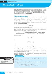
Measures to be taken to prevent electric shock by direct contact include (Regulation 412):<br />
(i) protection by insulating live parts<br />
(ii) protection by barriers or enclosures<br />
(iii) protection by obstacles, so preventing access<br />
(iv) protection by placing out of reach<br />
(v) IP codes/ratings are applied to electrical equipment to create an industry<br />
st<strong>and</strong>ard. These are covered below.<br />
RCDs (residual contact devices) may be used as a supplementary means of shock<br />
prevention from direct contact, but only in addition to the measures listed in (i) to (v)<br />
above. We will look further at RCDs in chapter 12, pages 307–308.<br />
Barriers or enclosures<br />
All live electrical components should be within enclosures. In some cases they will<br />
also be protected by barriers, preventing easy access from the public.<br />
In order to make sure that these requirements are followed correctly, an index of<br />
protection codes is applied to electrical equipment enclosures to create an industry<br />
st<strong>and</strong>ard. The first number in the code relates to the protection against direct contact<br />
in terms of the degree of accessibility, e.g. IP2X means that there is no contact with a<br />
probe of more than 12mm in diameter <strong>and</strong> less than 80mm long (approximately the<br />
length of a human finger). IPXXB is as above but for probes up to a maximum of<br />
80mm. IP4X is used for protection against wires of 1 mm in diameter.<br />
The horizontal top surface of the barrier or enclosure, which is readily accessible,<br />
should be protected to IP4X.<br />
Protection against indirect contact<br />
��������<br />
������ ���� ������ � �������<br />
�<br />
In this situation, conductive parts, such as metalwork, have become live due to fault<br />
conditions. The potential voltage on this metalwork rises above that of earth <strong>and</strong><br />
electric shock results when a person touches the metalwork.<br />
Measures taken to prevent electric shock by indirect contact include (Section 413<br />
in BS 7671) the following.<br />
(i) Earthed equipotential bonding <strong>and</strong> the automatic disconnection of the supply<br />
(EEBAD).
(ii) Use of class II equipment <strong>and</strong>/or equivalent insulation. Class II usually relates<br />
to portable equipment or factory-built equipment. Equipment to this class must<br />
not have enclosing metalwork earthed. Furthermore for a class II installation,<br />
close supervision is required to ensure the installation or its equipment is not<br />
changed from class II. The symbol on the equipment that indicates that it is class<br />
II or double insulated is a square within a square.<br />
(iii) Non-conducting location, i.e. physical separation from exposed conductive<br />
parts, no earth connection.<br />
(iv) Earth free local equipotential bonding. Every part is bonded <strong>and</strong> therefore ‘no<br />
voltage difference – no shock’.<br />
(v) Electrical separation. A transformer fed secondary is not connected to earth or<br />
an isolated generator supply is used.<br />
Methods (iii) to (v) have a limited application, as close supervision is required. The<br />
design must be specified by a qualified electrical engineer. The basic limitation of<br />
these methods is the need to maintain their design condition. There should be no<br />
incorrect modifications, additions or deterioration.<br />
Overcurrent protection<br />
Protection devices<br />
In a healthy electrical system, insulation between phase conductors <strong>and</strong> neutral<br />
conductors or between live conductors <strong>and</strong> earth is sound, with current flowing from<br />
the supply, through the load <strong>and</strong> returning via the neutral to its source.<br />
Overcurrent protection is provided by means of a circuit breaker or fuse. These<br />
devices are designed to operate within specified limits, disconnecting the supply<br />
automatically in the event of an overload or fault current (short circuits or earth faults).<br />
Earth-fault protection is also provided by means of a circuit breaker or fuse, which<br />
operates under earth-fault conditions. If a high value current flows, these will safely<br />
disconnect the supply but may not be relied upon to detect <strong>and</strong> disconnect the<br />
supply in the event of low values of earth leakage current.<br />
Residual current devices (RCDs) are designed to detect <strong>and</strong> automatically disconnect<br />
the supply in the event of earth-faults. Earth-faults can exist, for example, when a<br />
live conductor touches an equipment case or if you cut through a cable when cutting<br />
the grass. They are potentially dangerous <strong>and</strong> must be eliminated in order to prevent<br />
hazards resulting from electric shock or abnormal temperature rises <strong>and</strong> fires in the<br />
electrical installation.<br />
Overcurrent protection device applies to fuses <strong>and</strong> miniature circuit breakers<br />
(MCBs). In this section we will be looking at the various means by which these<br />
devices provide protection to cables <strong>and</strong> circuits from damage caused by too much<br />
current flowing. The appropriate device must operate within 0.4 or 5.0 seconds.<br />
<strong>Chapter</strong> 6 Basic electrical circuitry <strong>and</strong> applications<br />
147
<strong>NVQ</strong>2 Electrical Installations<br />
Definition<br />
Overload – an<br />
overcurrent occuring<br />
in a circuit which is<br />
electrically sound<br />
Remember<br />
The priority of the<br />
protective device is<br />
to protect the circuit<br />
conductors, not the<br />
appliance or the user<br />
148<br />
Overload <strong>and</strong> short circuit protection<br />
All circuit conductors must be sized correctly <strong>and</strong> must be of the correct<br />
current-carrying capacity for the load that they have to carry. All circuits on an<br />
installation must be protected against overcurrent. This is a current exceeding<br />
the rated value or current-carrying capacity of the cable conductor. Overcurrent<br />
conditions arise from either overloads or short circuits.<br />
Overload current occurs in a circuit which is electrically sound, i.e. a circuit now<br />
carrying more current than it was designed to carry due to faulty equipment or too<br />
many pieces of equipment connected to the circuit. Overload is only a temporary<br />
fault condition <strong>and</strong> is easily corrected. Examples of how overload occurs include:<br />
●<br />
●<br />
several 13 A plugs connected to an adaptor <strong>and</strong> then plugged into one 13 amp<br />
socket outlet<br />
a stalled motor.<br />
Such conditions cause the cable temperature to rise, resulting in an increased fire risk.<br />
Fault current is the level of current flowing at a level up to <strong>and</strong> including the<br />
prospective short circuit current (the prospective short circuit current being the<br />
maximum current that the supply transformer is capable of delivering).<br />
The prospective short circuit current must also be taken into account when selecting<br />
the type of overcurrent device to be installed.<br />
This fault occurs at a point between live conductors of negligible ������ ���� ������ impedance � ������� or<br />
�<br />
between a live conductor <strong>and</strong> an exposed conductive part. It is more serious than an<br />
overload current <strong>and</strong> will usually not be as easily corrected.<br />
Examples of faults are: a wiring fault (live connected to neutral or earth by mistake);<br />
a nail or screw being driven through an energised cable, making contact with the live<br />
conductors <strong>and</strong> either neutral or earth conductors.<br />
A fuse is the weak link in a circuit which will melt when too much current flows, thus<br />
protecting the circuit conductors from damage.<br />
Calculation of the cable size therefore automatically involves the correct selection of<br />
protective devices.<br />
Activity<br />
��������<br />
������ ���� ������ � �������<br />
�<br />
��������<br />
Have a look at the consumer unit in your own home <strong>and</strong> see how<br />
many circuits there are <strong>and</strong> how many outlets are supplied by each<br />
circuit. Do you think the way your house’s circuits have been divided<br />
up is reasonable? If not, why not?
FAQ<br />
Q What’s the difference between an mcb <strong>and</strong> an RCD?<br />
A An mcb is an overcurrent protective device. Like a fuse, it is designed to<br />
disconnect the circuit if the current flowing is excessive. An RCD measures the<br />
current flowing in the phase <strong>and</strong> neutral conductors, <strong>and</strong> will trip out if the<br />
difference between them (the residual current) exceeds the rated value.<br />
Q Why do I have to put coloured sleeving on switch wires <strong>and</strong> ‘strappers’.<br />
A Many accidents have occurred as a result of ‘mistaken identity’ of conductors,<br />
so marking them is essential. It is even more important since the 2004–2006<br />
colour coding changes. It is possible to have a blue conductor that could be an<br />
old phase conductor or a new neutral. Similarly, black conductors could be old<br />
neutrals or new phases. Extreme caution is necessary!<br />
Q Can I spur off the immersion heater circuit to supply the central<br />
heating system?<br />
A No. Immersion heaters supplying vessels containing more than 15 litres of water<br />
must be permanently connected to their own separate circuit.<br />
Q Why is a spur off a ring circuit called a ‘non-fused spur’?<br />
A Because a spur connected in this way breaks one of the ‘golden rules’ of circuit<br />
design, i.e. the fuse size (30/32 A) should always be smaller than the conductor<br />
current carrying capacity (27 A for 2.5mm 2 , clipped direct), which it isn’t!<br />
Therefore it is called unfused because the circuit fuse is too big to protect the<br />
spur cable.<br />
Q What protects a non-fused spur cable from overload, then?<br />
A Well, in a sense the spur cable is protected by the maximum load that can be<br />
connected to it. This 2 x 13 A socket outlets or 26 A, drawn through a 27 A cable.<br />
Now you see why ‘spurs off spurs’ are not allowed as, with two twin socket outlets,<br />
you could have 4 x 13 A – in other words 52 A flowing through a 27 A cable!<br />
Q Why do properties have more than one ring circuit even though the floor<br />
area is less than 100m?<br />
A Remember that the unlimited number of socket outlets per A1 ring circuit rule<br />
is always subject to loading. With the number of appliances increasing all the<br />
time, it would be very easy to overload a single ring circuit. Also the Regulations<br />
tell us to divide the circuits up to ‘minimise inconvenience in the event of a fault’<br />
so it is not a good idea to have all outlets on one circuit. This is especially true of<br />
lighting circuits where loss of one circuit should not result in the loss of lighting<br />
on that floor of a building.<br />
<strong>Chapter</strong> 6 Basic electrical circuitry <strong>and</strong> applications<br />
149
<strong>NVQ</strong>2 Electrical Installations<br />
150<br />
Knowledge check<br />
1. List five types of circuit protection device <strong>and</strong> their BS numbers. Which<br />
of these are overcurrent protective devices <strong>and</strong> which are residual<br />
current devices?<br />
2. Draw circuit <strong>and</strong> wiring diagrams for the following circuits.<br />
• One-way lighting circuit.<br />
• Two-way lighting circuit.<br />
• Two-way <strong>and</strong> intermediate lighting circuit.<br />
3. How many socket outlets can be installed in a st<strong>and</strong>ard (A1) domestic ring circuit?<br />
4. What is the maximum floor area st<strong>and</strong>ard domestic A2 <strong>and</strong> A3 radial circuits can<br />
serve?<br />
5. What is the maximum floor area that a domestic ring circuit can serve when<br />
protected by a 30/32 A protective device?<br />
6. What is the total number of fused spurs that could be fitted to a st<strong>and</strong>ard domestic<br />
ring circuit? What would be the limitation of this arrangement?<br />
7. Define the terms exposed conductive parts <strong>and</strong> extraneous conductive parts.<br />
8. Draw a labelled diagram showing the earth-fault loop path.<br />
9. What is the minimum degree of protection allowed for protection by barriers or<br />
enclosures?<br />
10. Explain the difference between an ‘overload current’ <strong>and</strong> a ‘short circuit current’.