Pump Specifications - Aqua Blast
Pump Specifications - Aqua Blast
Pump Specifications - Aqua Blast

Create successful ePaper yourself
Turn your PDF publications into a flip-book with our unique Google optimized e-Paper software.
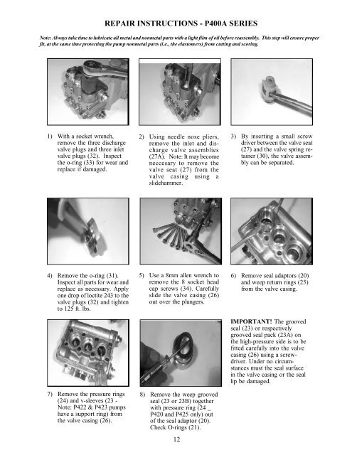
REPAIR INSTRUCTIONS - P400A SERIESNote: Always take time to lubricate all metal and nonmetal parts with a light film of oil before reassembly. This step will ensure properfit, at the same time protecting the pump nonmetal parts (i.e., the elastomers) from cutting and scoring.1) With a socket wrench,remove the three dischargevalve plugs and three inletvalve plugs (32). Inspectthe o-ring (33) for wear andreplace if damaged.2) Using needle nose pliers,remove the inlet and dischargevalve assemblies(27A). Note: It may becomeneccesary to remove thevalve seat (27) from thevalve casing using aslidehammer.3) By inserting a small screwdriver between the valve seat(27) and the valve spring retainer(30), the valve assemblycan be separated.4) Remove the o-ring (31).Inspect all parts for wear andreplace as necessary. Applyone drop of loctite 243 to thevalve plugs (32) and tightento 125 ft. lbs.7) Remove the pressure rings(24) and v-sleeves (23 -Note: P422 & P423 pumpshave a support ring) fromthe valve casing (26).5) Use a 8mm allen wrench toremove the 8 socket headcap screws (34). Carefullyslide the valve casing (26)out over the plungers.8) Remove the weep groovedseal (23 or 23B) togetherwith pressure ring (24 _P420 and P425 only) outof the seal adaptor (20).Check O-rings (21).126) Remove seal adaptors (20)and weep return rings (25)from the valve casing.IMPORTANT! The groovedseal (23) or respectivelygrooved seal pack (23A) onthe high-pressure side is to befitted carefully into the valvecasing (26) using a screwdriver.Under no circumstancesmust the seal surfacein the valve casing or the seallip be damaged.