Dell PowerVault TL2000 Tape Library and TL4000 Tape Library ...
Dell PowerVault TL2000 Tape Library and TL4000 Tape Library ...
Dell PowerVault TL2000 Tape Library and TL4000 Tape Library ...

You also want an ePaper? Increase the reach of your titles
YUMPU automatically turns print PDFs into web optimized ePapers that Google loves.
<strong>Dell</strong> <strong>PowerVault</strong> <strong>TL2000</strong> <strong>Tape</strong> <strong>Library</strong> <strong>and</strong> <strong>TL4000</strong><strong>Tape</strong> <strong>Library</strong>User's Guide
<strong>Dell</strong> <strong>PowerVault</strong> <strong>TL2000</strong> <strong>Tape</strong> <strong>Library</strong> <strong>and</strong> <strong>TL4000</strong><strong>Tape</strong> <strong>Library</strong>User's Guide
Information in this document is subject to change without notice.© 2011 <strong>Dell</strong> Inc. All rights reserved.Reproduction in any manner whatsoever without the written permission of <strong>Dell</strong> Inc. is strictly forbidden.Trademarks used in this text: <strong>Dell</strong>, the DELL logo <strong>and</strong> <strong>PowerVault</strong> are trademarks of <strong>Dell</strong> Inc.Other trademarks <strong>and</strong> trade names may be used in this document to refer to either the entities claiming the marks<strong>and</strong> names or their products. <strong>Dell</strong> Inc. disclaims any proprietary interest in trademarks <strong>and</strong> trade names other thanits own.Printed 2011
Read This FirstMinimum Firmware Levels for Common <strong>Library</strong> FeaturesTable 1. Minimum Firmware Levels for common <strong>Library</strong> featuresFeatureLTO HH V2 <strong>Tape</strong> DrivesLTO 5 <strong>Tape</strong> Drive<strong>Library</strong> BCR (Bar Code Reader)Dedicated Cleaning Slot removalEncryptionMinimum Firmware Level(s) Required<strong>Library</strong> firmware level must be at 10.00, orgreater, to support HH V2 <strong>Tape</strong> Drives.<strong>Library</strong> firmware must be at 9.00, or greater,to support the Ultrium 5 drives. Ensure theminimum version required to supportUltrium 5 tape drives are installed on thehost. Ensure any host applications <strong>and</strong>software, that use their own device drivers,are at the minimum level required tosupport Ultrium 5 tape drives.Libraries manufactured after May 2010 mayhave a BCR that requires a minimum levelof library firmware. The minimum level offirmware for these libraries is 9.00. Attemptsto downlevel these libraries below 9.00 willbe blocked by the library.<strong>Library</strong> firmware level must be greater than3.90.<strong>Library</strong> firmware level must be 5.80 orgreater.LTO4 Drive firmware level must be 77BE orgreater.Key Path Diagnostics<strong>Library</strong> firmware level must be greater than6.3, if feature is available.Path FailoverLTO 4 <strong>Tape</strong> Drives: No minimum level offirmware is required.IPv6 Support <strong>Library</strong> firmware level: 4.50Contacting <strong>Dell</strong>For customers in the United States, call 800-WWW-DELL (800-999-3355).Note: If you do not have an active Internet connection, you can find contactinformation on your purchase invoice, packing slip, bill, or <strong>Dell</strong> productcatalog.<strong>Dell</strong> provides several online <strong>and</strong> telephone-based support <strong>and</strong> service options.Service availability varies by country <strong>and</strong> product, <strong>and</strong> some services may not beavailable in your area. To contact <strong>Dell</strong> for sales, technical support, or customerservice issues follow the steps listed below:1. Visit http://support.dell.com.2. Verify your country or region in the Choose A Country/Region drop-downmenu at the bottom of the page.iii
3. Click Contact Us on the left side of the page.4. Select the appropriate service or support link based on your need.5. Choose the method of contacting <strong>Dell</strong> that is convenient for you.iv<strong>Dell</strong> <strong>PowerVault</strong> <strong>TL2000</strong> <strong>Tape</strong> <strong>Library</strong> <strong>and</strong> <strong>TL4000</strong> <strong>Tape</strong> <strong>Library</strong> User's Guide
ContentsRead This First . . . . . . . . . . . iiiMinimum Firmware Levels for Common <strong>Library</strong>Features . . . . . . . . . . . . . . . iiiContacting <strong>Dell</strong> . . . . . . . . . . . . . iiiFigures . . . . . . . . . . . . . . viiTables . . . . . . . . . . . . . . . xiSafety <strong>and</strong> Environmental Notices . . xiiiDanger Notice . . . . . . . . . . . . . xiiiCaution Notice . . . . . . . . . . . . . xiiiLaser Safety <strong>and</strong> Compliance . . . . . . . . xivClass I Laser Product . . . . . . . . . . xivPerforming the Safety Inspection Procedure . . . xivRack Safety . . . . . . . . . . . . . . xvPreface . . . . . . . . . . . . . . xixRelated Publications . . . . . . . . . . . xixChapter 1. Product Description . . . . 1-1Front Panel . . . . . . . . . . . . . . 1-1Rear Panel . . . . . . . . . . . . . . 1-3Bar Code Reader . . . . . . . . . . . . 1-6Encryption . . . . . . . . . . . . . . 1-6Supported Internet Protocols . . . . . . . . 1-7SNMP Messaging . . . . . . . . . . . . 1-7SNMP Traps . . . . . . . . . . . . . 1-7Maximum <strong>Library</strong> Storage Capacity <strong>and</strong> DataTransfer Rate . . . . . . . . . . . . . 1-8Ultrium <strong>Tape</strong> Drives . . . . . . . . . . . 1-9Speed Matching . . . . . . . . . . . 1-10Channel Calibration . . . . . . . . . . 1-10Power Management . . . . . . . . . . 1-11Media . . . . . . . . . . . . . . . 1-11<strong>Library</strong> Specifications . . . . . . . . . . 1-11Product Environment . . . . . . . . . . 1-13Supported Device Drivers . . . . . . . . . 1-14Chapter 2. User Interfaces . . . . . . 2-1Operator Control Panel . . . . . . . . . . 2-1Operator Control Panel Philosophy . . . . . 2-1Power-ON Display. . . . . . . . . . . 2-2Note about the Front Panel LEDs . . . . . . 2-2Input Modes . . . . . . . . . . . . . 2-3Power ON/OFF . . . . . . . . . . . 2-4Web User Interface. . . . . . . . . . . . 2-4Login . . . . . . . . . . . . . . . 2-5System Status . . . . . . . . . . . . 2-6Web User Interface Help Pages . . . . . . 2-8Logging out of the Web User Interface . . . . 2-8Chapter 3. Installation Planning. . . . 3-1Determining the Number of Logical Libraries. . . 3-1Basic Guidelines . . . . . . . . . . . 3-1<strong>Library</strong> Sharing . . . . . . . . . . . . 3-1Using Multiple Logical Libraries for <strong>Library</strong>Sharing . . . . . . . . . . . . . . 3-2Using Multiple Control Paths . . . . . . . . 3-2Using Multiple Control Paths for Path Failover 3-2<strong>Library</strong> Partitioning <strong>and</strong> Element Addressing . . . 3-2Logical Unit Number (LUN) Scanning . . . . . 3-6Host Interfaces . . . . . . . . . . . . . 3-7SCSI Interface . . . . . . . . . . . . 3-7SAS Interface . . . . . . . . . . . . 3-9Fibre Channel Interface . . . . . . . . . 3-9Chapter 4. Installation <strong>and</strong>Configuration . . . . . . . . . . . 4-1Using the <strong>Library</strong> Configuration Form . . . . . 4-1Installing Your <strong>Library</strong> . . . . . . . . . . 4-1Choosing a Location . . . . . . . . . . 4-1Unpacking the <strong>Library</strong> . . . . . . . . . 4-2Verifying the Shipment . . . . . . . . . 4-2Installing the <strong>Library</strong> Foot Pads (for DesktopInstallation ONLY). . . . . . . . . . . 4-3Removing <strong>and</strong> Storing the Shipping Lock . . . 4-4Rackmounting the <strong>Library</strong> (for Rack InstallationONLY). . . . . . . . . . . . . . . 4-6Connecting the Host Interface Cable . . . . 4-11Connecting a Power Cord . . . . . . . . 4-13Configuring Your <strong>Library</strong> . . . . . . . . . 4-14Choosing Your Configuration Method . . . . 4-14Using Factory Defaults as Your Configuration 4-14Configuring Your <strong>Library</strong> using the Web UserInterface . . . . . . . . . . . . . . 4-15Configuring Your <strong>Library</strong> using the OperatorControl Panel . . . . . . . . . . . . 4-31Preparing the Host . . . . . . . . . . . 4-31Verifying the Connection . . . . . . . . . 4-32Cartridge Magazines. . . . . . . . . . . 4-32Populating the <strong>Library</strong> with Data Cartridges 4-36Inserting the Cleaning Cartridge . . . . . . 4-37Chapter 5. Operations . . . . . . . . 5-1Operator Control Panel Navigation . . . . . . 5-7Operator Control Panel Menu Tree . . . . . . 5-9Monitor Menu . . . . . . . . . . . . 5-10Control Menu . . . . . . . . . . . . 5-16Configure Menu . . . . . . . . . . . 5-18Service Menu . . . . . . . . . . . . 5-30Web User Interface Menus . . . . . . . . . 5-33Monitor <strong>Library</strong> Menu . . . . . . . . . 5-34Manage <strong>Library</strong> Menu . . . . . . . . . 5-42Configure <strong>Library</strong> Menu . . . . . . . . 5-44Service <strong>Library</strong> Menu . . . . . . . . . 5-57Import <strong>and</strong> Export Media during Normal <strong>Library</strong>Operation . . . . . . . . . . . . . . 5-64Configuring I/O Stations <strong>and</strong> Reserving Slots . . 5-65v
Chapter 6. Using Ultrium Media . . . . 6-1Data Cartridges . . . . . . . . . . . . . 6-1Cartridge Compatibility . . . . . . . . . 6-2WORM (Write Once, Read Many). . . . . . . 6-3WORM Media . . . . . . . . . . . . 6-3Data Security on WORM Media . . . . . . 6-3WORM Media Errors . . . . . . . . . . 6-3Cleaning Cartridge. . . . . . . . . . . . 6-4Bar Code Label . . . . . . . . . . . . . 6-4Guidelines for Using Bar Code Labels . . . . 6-5Write-Protect Switch . . . . . . . . . . . 6-6H<strong>and</strong>ling the Cartridges . . . . . . . . . . 6-7Provide Training . . . . . . . . . . . 6-7Ensure Proper Packaging . . . . . . . . 6-7Provide Proper Acclimation <strong>and</strong> EnvironmentalConditions . . . . . . . . . . . . . 6-8Perform a Thorough Inspection . . . . . . 6-8H<strong>and</strong>le the Cartridge Carefully . . . . . . 6-9Environmental <strong>and</strong> Shipping Specifications for <strong>Tape</strong>Cartridges . . . . . . . . . . . . . . 6-9Chapter 7. Troubleshooting . . . . . 7-1Installation Problems . . . . . . . . . . . 7-6<strong>Library</strong> Recovery Problem Determination . . . . 7-6Procedures for Isolating CRU Problems . . . . . 7-7Isolating a Power Supply Problem . . . . . 7-7Isolating Drive Sled Problems . . . . . . . 7-9Isolating a <strong>Library</strong> Controller Card vs. AccessorEnclosure Problem . . . . . . . . . . 7-10Isolating Web User Interface Problems . . . . 7-11Isolating Accessor Scanner Problems . . . . 7-11Isolating Host Attachment Interface Problems 7-12Identifying a Suspect Cartridge . . . . . . . 7-12Chapter 8. Error Codes . . . . . . . 8-1Chapter 9. Service Procedures . . . . 9-1Removing Cartridges from Magazine Slots. . . . 9-1Releasing the Magazines Manually . . . . . . 9-1Using the ITDT Firmware Update, Dump Retrieval<strong>and</strong> Drive Test Tool . . . . . . . . . . . 9-4Chapter 10. Check, Adjust, Remove,<strong>and</strong> Replace . . . . . . . . . . . 10-1Tools Required. . . . . . . . . . . . . 10-1Electrostatic Discharge . . . . . . . . . . 10-1Relocating Your <strong>Library</strong>. . . . . . . . . . 10-1Removing/Installing/Adding a <strong>Tape</strong> Drive Sled 10-3Removing a <strong>Tape</strong> Drive Sled . . . . . . . 10-4Installing a <strong>Tape</strong> Drive Sled . . . . . . . 10-6Adding a <strong>Tape</strong> Drive Sled . . . . . . . . 10-9Replacing a Power Supply . . . . . . . . 10-10Replacing a <strong>Library</strong> Controller Card . . . . . 10-11Replacing Cartridge Magazines . . . . . . . 10-13Replacing the <strong>Library</strong> Enclosure . . . . . . 10-13Preparing the Defective <strong>Library</strong> forReplacement . . . . . . . . . . . . 10-13Unpacking <strong>and</strong> Preparing the Replacement<strong>Library</strong> Enclosure . . . . . . . . . . 10-14Installing Your Drive(s) in the Replacement<strong>Library</strong> Enclosure . . . . . . . . . . 10-16Power Supplies . . . . . . . . . . . 10-18<strong>Library</strong> Controller Card . . . . . . . . 10-19Swapping Cartridge Magazines. . . . . . 10-20Installing the Replacement <strong>Library</strong> Enclosure 10-22Completing the Installation of theReplacement <strong>Library</strong> Enclosure . . . . . . 10-24Returning the Defective <strong>Library</strong> Enclosure 10-24Appendix A. SCSI Element Types,SCSI Addresses, <strong>and</strong> PhysicalConfigurations . . . . . . . . . . . A-12U <strong>Library</strong> I/O Slot, Storage Slots <strong>and</strong> Drive SlotElement Addresses <strong>and</strong> Physical Locations . . . A-14U <strong>Library</strong> I/O Slots, Storage Slots, <strong>and</strong> DriveSlots Element Addresses <strong>and</strong> Physical Locations . A-2<strong>Library</strong> Partitioning <strong>and</strong> Element Addressing . . A-3Appendix B. <strong>Tape</strong>Alert Flags . . . . . B-1<strong>Tape</strong>Alert Flags Supported by the <strong>Library</strong> . . . . B-1<strong>Tape</strong>Alert Flags Supported by the Drive . . . . B-2Appendix C. Sense Data . . . . . . . C-1<strong>Library</strong> Sense Data . . . . . . . . . . . C-1Drive Sense Data . . . . . . . . . . . . C-6Appendix D. Enabling LUN Support inLinux . . . . . . . . . . . . . . . D-1Red Hat Enterprise Linux . . . . . . . . . D-2Enabling LUN Support in Netware . . . . . . D-2Appendix E. Notes on IPv6Compatibility with Windows 2003/XP<strong>and</strong> 2008/Vista . . . . . . . . . . . E-1Notes on IPv6 Compatibility with Linux . . . . E-2Appendix F. SNMP Status MIBVariables <strong>and</strong> Traps . . . . . . . . . F-1Appendix G. <strong>Library</strong> ConfigurationForm . . . . . . . . . . . . . . . G-1Appendix H. Accessibility . . . . . . H-1Glossary . . . . . . . . . . . . . . I-1Index . . . . . . . . . . . . . . . X-1vi<strong>Dell</strong> <strong>PowerVault</strong> <strong>TL2000</strong> <strong>Tape</strong> <strong>Library</strong> <strong>and</strong> <strong>TL4000</strong> <strong>Tape</strong> <strong>Library</strong> User's Guide
Figures1-1. Front panel of a 2U library . . . . . . 1-11-2. Front panel of a 4U library . . . . . . 1-21-3. Rear panel of a 2U library with a SCSI drive 1-31-4. Rear panel of a 4U library with full heightFibre Channel drive <strong>and</strong> half height SCSI<strong>and</strong> SAS drives . . . . . . . . . . 1-41-5. Rear panel of a 2U library with a full heightdual port SAS drive . . . . . . . . . 1-41-6. <strong>Library</strong> drive sled without ESD springs(SCSI sled shown) . . . . . . . . . 1-101-7. <strong>Library</strong> drive sled with ESD springs [1](SAS sled shown) . . . . . . . . . 1-102-1. Power-ON screens . . . . . . . . . 2-22-2. Web User Interface login page . . . . . 2-62-3. 2U library System Status screen . . . . . 2-62-4. 4U library System Status screen . . . . . 2-62-5. 4U library System Status screen showingmedia attention status . . . . . . . . 2-72-6. 4U library System Status screen showing apower supply failure . . . . . . . . 2-73-1. Configuration of a one - partition system 3-43-2. Configuration of a two - partition system 3-43-3. Configuration of a three - partition system 3-53-4. Configuration of a four - partition system 3-53-5. Examples of SCSI element addressing 3-64-1. Installing foot pads on the bottom of thelibrary enclosure . . . . . . . . . . 4-44-2. Shipping lock <strong>and</strong> label . . . . . . . 4-54-3. <strong>Library</strong> shipping lock <strong>and</strong> label storagelocation . . . . . . . . . . . . . 4-54-4. Rack Kit mounting hardware. . . . . . 4-74-5. Examples of EIA units for round hole <strong>and</strong>square hole installations . . . . . . . 4-74-6. Rear view of a rack showing the narrowpart of the rail. . . . . . . . . . . 4-84-7. 2U library side screws to remove . . . . 4-84-8. 2U library rack anchors <strong>and</strong> mountingbrackets . . . . . . . . . . . . . 4-94-9. Sliding the 2U library into the rack 4-94-10. Sliding the 4U library into the rack 4-104-11. Securing the 2U library to the rack 4-104-12. Securing the 4U library to the rack 4-114-13. Attaching a SCSI host interface cable to the2U library . . . . . . . . . . . . 4-124-14. Attaching host interface cables to the 4Ulibrary . . . . . . . . . . . . . 4-124-15. Attaching a SAS interface cable to the 2Ulibrary . . . . . . . . . . . . . 4-124-16. Removing the protective label from thepower receptacle . . . . . . . . . 4-134-17. Log in screen on the Web User Interface 4-184-18. The 2U library Configure <strong>Library</strong>: Generalscreen . . . . . . . . . . . . . 4-204-19. Example: The 4U library Configure<strong>Library</strong>: General screen . . . . . . . 4-204-20. The 4U library Configure <strong>Library</strong>: LogicalLibraries page . . . . . . . . . . 4-214-21. The Configure <strong>Library</strong>: Path FailoverFeature Activation screen. . . . . . . 4-214-22. Feature Key verification screen . . . . . 4-224-23. Feature Activation Key screen . . . . . 4-224-24. Configure <strong>Library</strong>: Encryption Activationscreen . . . . . . . . . . . . . 4-234-25. The Configure <strong>Library</strong>: Drive screen 4-244-26. Configure <strong>Library</strong>: Network Page 4-254-27. Warning Screen . . . . . . . . . . 4-264-28. The Configure <strong>Library</strong>: User Access screen 4-274-29. The Configure <strong>Library</strong>: Date <strong>and</strong> Timescreen . . . . . . . . . . . . . 4-284-30. The Configure <strong>Library</strong>: Logs <strong>and</strong> Tracesscreen . . . . . . . . . . . . . 4-284-31. The Configure <strong>Library</strong>: Email Notificationscreen . . . . . . . . . . . . . 4-294-32. Configure <strong>Library</strong>: SNMP Page 4-304-33. 2U library left magazine . . . . . . . 4-334-34. 2U library right magazine . . . . . . 4-334-35. 2U library I/O Station in the left magazine 4-344-36. 4U library left magazines. . . . . . . 4-344-37. 4U library right magazines . . . . . . 4-354-38. 4U library I/O Station in the lower leftmagazine . . . . . . . . . . . . 4-354-39. Finger Holes on back side of 4U libraryI/O Station . . . . . . . . . . . 4-365-1. 2U <strong>Library</strong> Control Keys . . . . . . . 5-85-2. 4U <strong>Library</strong> Control Keys . . . . . . . 5-85-3. Operator Control Panel Menu Tree 5-105-4. Monitor: <strong>Library</strong> menu . . . . . . . 5-115-5. Monitor: Drive menu . . . . . . . . 5-135-6. Example of a 4U Monitor: Inventory menu 5-155-7. Overview of inventoried cartridges: LowerLeft Magazine of a 4U <strong>Library</strong> . . . . . 5-155-8. Detailed information on cartridges residingin a magazine . . . . . . . . . . 5-165-9. Control: I/O Station menu . . . . . . 5-165-10. Control: Move Cartridges menu 5-175-11. Control: Magazine menu . . . . . . . 5-175-12. Control: Re-Inventory menu. . . . . . 5-185-13. Configure: Logical Libraries menu 5-195-14. Configure: <strong>Library</strong> menu . . . . . . . 5-205-15. Configure: Drive menu . . . . . . . 5-235-16. Configure: Network menu . . . . . . 5-245-17. Configure: Set Access PIN menu 5-265-18. Pound sign (#) shows accessible menuswhen access PIN is enabled but before it isentered. . . . . . . . . . . . . 5-275-19. Configure: Save/Restore menu . . . . . 5-275-20. Configure: Set Date <strong>and</strong> Time menu 5-295-21. Configure: Path Failover . . . . . . . 5-305-22. Service: <strong>Library</strong> Verify menu . . . . . 5-305-23. Service: Run Tests menu . . . . . . . 5-315-24. Service: Service menu . . . . . . . . 5-32vii
5-25. Service: Display Contrast menu 5-335-26. The 4U library Monitor <strong>Library</strong>: <strong>Library</strong>Identity page. . . . . . . . . . . 5-355-27. The 4U library Monitor <strong>Library</strong>: DriveIdentity page showing one Ultrium 3 SAShalf high V2 drive (#1) <strong>and</strong> one Ultrium 4SAS half high drive (#2) . . . . . . . 5-375-28. The 4U library Monitor <strong>Library</strong>: <strong>Library</strong>Status page . . . . . . . . . . . 5-385-29. The 4U library Monitor <strong>Library</strong>: DriveStatus page . . . . . . . . . . . 5-405-30. The 2U library Monitor <strong>Library</strong>: Inventorypage . . . . . . . . . . . . . 5-415-31. The 4U library Monitor <strong>Library</strong>: Inventorypage . . . . . . . . . . . . . 5-425-32. Manage <strong>Library</strong>: Move Media page 5-435-33. Manage <strong>Library</strong>: Perform Inventory page 5-435-34. Manage <strong>Library</strong>: Release Magazine page 5-435-35. The 4U library Configure <strong>Library</strong>: General<strong>and</strong> Extended page. . . . . . . . . 5-455-36. The 4U library Configure <strong>Library</strong>: LogicalLibraries page . . . . . . . . . . 5-465-37. The 4U library Configure <strong>Library</strong>: PathFailover page . . . . . . . . . . 5-465-38. Path Failover license verification page 5-465-39. Feature Activation Key screen . . . . . 5-475-40. Configure <strong>Library</strong>: Encryption Featureconfiguration screen . . . . . . . . 5-485-41. The Configure <strong>Library</strong>: Drives page for a2U library . . . . . . . . . . . . 5-505-42. The Configure <strong>Library</strong>: Drives page for a4U library . . . . . . . . . . . . 5-505-43. Configure <strong>Library</strong>: Network Page 5-515-44. Warning Screen . . . . . . . . . . 5-525-45. Configure <strong>Library</strong>: User Access page 5-535-46. The Configure <strong>Library</strong>: Date & Time page 5-545-47. Configure <strong>Library</strong>: Logs & Traces page 5-545-48. Configure <strong>Library</strong>: Email Notification page 5-555-49. Configure <strong>Library</strong>: SNMP Page 5-565-50. Configure <strong>Library</strong>: Save/Restore page 5-575-51. No Cleaning Required . . . . . . . 5-585-52. No Cleaning Cartridge in <strong>Library</strong> 5-585-53. Service <strong>Library</strong>: Clean Drive page 5-585-54. Service <strong>Library</strong>: View Logs page 5-595-55. Service <strong>Library</strong>: View Drive Logs screen 5-605-56. Service: Save Drive Dump . . . . . . 5-605-57. Service <strong>Library</strong>: Perform Diagnostics page 5-615-58. Service <strong>Library</strong>: Perform Key PathDiagnostics page . . . . . . . . . 5-625-59. The Service <strong>Library</strong>: Upgrade Firmwarepage showing one Ultrium 3 SAS HalfHigh V2 drive <strong>and</strong> one Ultrium 4 SAS HalfHigh drive. . . . . . . . . . . . 5-635-60. Service <strong>Library</strong>: Reboot page . . . . . 5-646-1. The LTO Ultrium 1500 GB Data Cartridge 6-16-2. Ultrium Data <strong>and</strong> WORM <strong>Tape</strong> Cartridges 6-36-3. Sample bar code label on the LTO Ultrium 5<strong>Tape</strong> Cartridge . . . . . . . . . . 6-56-4. Setting the write-protect switch . . . . . 6-66-5. Double-boxing tape cartridges for shipping 6-86-6. Checking for gaps in the seams of acartridge . . . . . . . . . . . . 6-97-1. A 250w power supply with LEDs 7-77-2. A 80w power supply without LEDs 7-89-1. Access holes for the left magazine 9-19-2. Access holes for the right magazine 9-29-3. Left magazine pulled out of the 2U library 9-39-4. Left Magazines pulled out of the 4U <strong>Library</strong> 9-310-1. ESD label . . . . . . . . . . . . 10-110-2. Shipping Lock <strong>and</strong> Label Storage Location 10-210-3. Shipping Lock <strong>and</strong> Label. . . . . . . 10-210-4. <strong>Library</strong> drive sled without ElectroStaticDischarge (ESD) springs (SCSI sled shown) 10-310-5. <strong>Library</strong> drive sled with ESD springs [1](SAS sled shown) . . . . . . . . . 10-410-6. Drive sled components (full-high fibredrive in top position, half-high SCSI drivein middle position, half-high SAS drive inbottom position) on back panel of a 4Ulibrary . . . . . . . . . . . . . 10-510-7. Pulling the drive sled out of the library(drive sled without ESD springs shown) . 10-610-8. Pushing the drive sled into the library(drive sled without ESD springs shown) . 10-710-9. Diagrams for applying conductive tape forESD protection to the back of a drive sledinstalled in a 2U or 4U library . . . . . 10-810-10. A power supply being removed from a2U library . . . . . . . . . . . 10-1110-11. A <strong>Library</strong> Controller Card being removedfrom the library . . . . . . . . . 10-1210-12. Removing the two mounting bracketscrews anchoring the library to the rack(one screw on each side of the library) . . 10-1410-13. Foot pads installed on the bottom of thelibrary enclosure . . . . . . . . . 10-1510-14. Removing the shipping label <strong>and</strong> lockfrom the top of the library <strong>and</strong> storing onthe rear panel . . . . . . . . . . 10-1610-15. <strong>Library</strong> shipping lock <strong>and</strong> label storagelocation on the real panel of the library . 10-1610-16. Removing a drive sled from the library(drive sled without ESD springs shown) . 10-1710-17. Drive sled taping diagrams . . . . . 10-1810-18. A power supply being removed from alibrary . . . . . . . . . . . . 10-1910-19. Removing a <strong>Library</strong> Controller Card fromthe library . . . . . . . . . . . 10-2010-20. Access hole for the left magazine (facingrear of library) . . . . . . . . . . 10-2010-21. Access hole for the right magazine (facingrear of library) . . . . . . . . . . 10-2110-22. Left magazines pulled out of a 4U library(facing front of library) . . . . . . . 10-2210-23. Mounting brackets <strong>and</strong> anchors forsecuring the library in a rack (one bracket<strong>and</strong> anchor on each side of the library). . 10-2310-24. Front view of rack showing screwplacement . . . . . . . . . . . 10-23A-1. Configuration of a one - partition system A-4A-2. Configuration of a two - partition system A-5viii<strong>Dell</strong> <strong>PowerVault</strong> <strong>TL2000</strong> <strong>Tape</strong> <strong>Library</strong> <strong>and</strong> <strong>TL4000</strong> <strong>Tape</strong> <strong>Library</strong> User's Guide
A-3. Configuration of a three - partition system A-5A-4. Configuration of a four - partition system A-6A-5. Examples of SCSI element addressing A-6Figuresix
x<strong>Dell</strong> <strong>PowerVault</strong> <strong>TL2000</strong> <strong>Tape</strong> <strong>Library</strong> <strong>and</strong> <strong>TL4000</strong> <strong>Tape</strong> <strong>Library</strong> User's Guide
Tables1. Minimum Firmware Levels for common<strong>Library</strong> features . . . . . . . . . . iii1-1. 2U library <strong>and</strong> 4U library front paneldescriptions . . . . . . . . . . . 1-21-2. 2U library <strong>and</strong> 4U library rear paneldescriptions . . . . . . . . . . . 1-51-3. <strong>Tape</strong> drive model <strong>and</strong> host interface type 1-81-4. <strong>Library</strong> storage capacity <strong>and</strong> data transferrate . . . . . . . . . . . . . . 1-81-5. Physical Specifications. . . . . . . . 1-111-6. Power Specifications . . . . . . . . 1-121-7. Operation Specifications: Ultrium 5 1-121-8. Operation Specifications: Ultrium 4 1-121-9. Operation Specifications: Ultrium 3 1-131-10. Environmental Specifications . . . . . 1-133-1. Host Drive Interface Support . . . . . . 3-73-2. Maximum bus length between terminators 3-83-3. Recommended maximum quantity of drivesper SCSI bus . . . . . . . . . . . 3-84-1. Location criteria . . . . . . . . . . 4-15-1. Menu navigation shortcuts . . . . . . 5-15-2. <strong>Library</strong> Control Keys . . . . . . . . 5-85-3. Detailed information on cartridges residingin a magazine . . . . . . . . . . 5-165-4. Factory Default Settings . . . . . . . 5-285-5. Web User Interface Menus . . . . . . 5-335-6. <strong>Library</strong> Identity page elements . . . . . 5-345-7. Drive Identity page elements . . . . . 5-355-8. <strong>Library</strong> Status page elements . . . . . 5-375-9. Drive Status page elements . . . . . . 5-385-10. Configure <strong>Library</strong>: General page elements 5-445-11. Configure <strong>Library</strong>: Specific page elements 5-445-12. Drive Identity page elements . . . . . 5-496-1. Nominal Cartridge Life: Load/UnloadCycles . . . . . . . . . . . . . 6-26-2. Ultrium data cartridge compatibility withUltrium tape drive . . . . . . . . . 6-26-3. Cartridges <strong>and</strong> VOLSERs compatible withthe Ultrium <strong>Tape</strong> Drives . . . . . . . 6-46-4. Location of the write-protect switch 6-66-5. Environment for operating, storing, <strong>and</strong>shipping the LTO Ultrium <strong>Tape</strong> Cartridge . 6-107-1. Troubleshooting table . . . . . . . . 7-17-2. Power Supply LED Meanings . . . . . 7-88-1. Main Error Codes . . . . . . . . . 8-28-2. Sub error codes . . . . . . . . . . 8-78-3. Warning Events . . . . . . . . . . 8-1110-1. Shipping Lock/Shipping Label . . . . . 10-2A-1. 2U library SCSI Element Types <strong>and</strong>Element Addresses . . . . . . . . . A-1A-2. 4U library SCSI Element Types <strong>and</strong>Element Addresses . . . . . . . . . A-1A-3. 2U library SCSI element addresses forstorage slots <strong>and</strong> drive slot (one logicalpartition with one drive) . . . . . . . A-2A-4. 4U library SCSI element addresses forstorage slots <strong>and</strong> drive slot (one logicalB-1.partition with drives in slot 1 <strong>and</strong> slot 2) . A-2<strong>Tape</strong>Alert Flags Supported by the Ultrium<strong>Tape</strong> Drive . . . . . . . . . . . . B-2C-1. <strong>Library</strong> Sense Keys, ASC <strong>and</strong> ASCQ C-1C-2. LTO <strong>Tape</strong> Drive Sense Data . . . . . . C-6F-1. SNMP Status Events . . . . . . . . F-1xi
xii<strong>Dell</strong> <strong>PowerVault</strong> <strong>TL2000</strong> <strong>Tape</strong> <strong>Library</strong> <strong>and</strong> <strong>TL4000</strong> <strong>Tape</strong> <strong>Library</strong> User's Guide
Safety <strong>and</strong> Environmental NoticesDanger NoticeWhen using this product, observe the danger, caution, <strong>and</strong> attention notices thatare contained in this guide. The notices are accompanied by symbols that representthe severity of the safety condition.The sections that follow define each type of safety notice <strong>and</strong> give examples.A danger notice calls attention to a situation that ispotentially lethal or extremely hazardous to people. Alightning bolt symbol always accompanies a danger noticeto represent a dangerous electrical condition.Caution NoticeA caution notice calls attention to a situation that is potentially hazardous topeople because of some existing condition. A caution notice can be accompaniedby one of several symbols:If the symbol is...It means....A hazardous electrical condition with less severity than electricaldanger.A generally hazardous condition not represented by other safetysymbols.A hazardous condition due to the use of a laser in the product. Lasersymbols are always accompanied by the classification of the laser asdefined by the U. S. Department of Health <strong>and</strong> Human Services (forexample, Class I, Class II, <strong>and</strong> so forth).A hazardous condition due to mechanical movement in or around theproduct.A hazardous condition due to the weight of the unit. Weight symbolsare accompanied by an approximation of the product's weight.32-55 kg (70.5-121.2 lbs)svc00168A hazardous condition due to the unit's susceptibility to electrostaticdischarge.xiii
Laser Safety <strong>and</strong> ComplianceBefore using the library, review the following laser safety information.Class I Laser ProductThe library may contain a laser assembly that complies with the performancest<strong>and</strong>ards set by the U.S. Food <strong>and</strong> Drug Administration for a Class I laserproduct. Class I laser products do not emit hazardous laser radiation. The libraryhas the necessary protective housing <strong>and</strong> scanning safeguards to ensure that laserradiation is inaccessible during operation or is within Class I limits. External safetyagencies have reviewed the library <strong>and</strong> have obtained approvals to the latestst<strong>and</strong>ards as they apply.Performing the Safety Inspection ProcedureBefore you service the unit, perform the following safety inspection procedure:1. Stop all the activities between the host <strong>and</strong> the library's tape drives.2. Turn off the power to the library by pushing in on the Power button (1)shown in Figure 1-1 on Page 1-1 for 4 seconds.3. If drives are SCSI attached, disconnect the SCSI cable <strong>and</strong> check the SCSI busterminator for damage.4. Unplug the library's power cord or cords from the electrical outlet <strong>and</strong> thelibrary power supply.5. Check the library's power cord for damage, such as a pinched, cut, or frayedcord.6. If drives are SCSI attached, check the tape drive's SCSI bus (signal) cable fordamage.7. If drives are FC/SAS attached, check the tape drive's FC/SAS cable fordamage.8. Check the cover of the library for sharp edges, damage, or alterations thatexpose its internal parts.9. Check the cover of the library for proper fit. It should be in place <strong>and</strong> secure.10. Check the product label at the rear of the library to make sure that it matchesthe voltage at your outlet.xiv<strong>Dell</strong> <strong>PowerVault</strong> <strong>TL2000</strong> <strong>Tape</strong> <strong>Library</strong> <strong>and</strong> <strong>TL4000</strong> <strong>Tape</strong> <strong>Library</strong> User's Guide
Rack SafetyThe following general safety information should be used for all rack mounteddevices.DANGERvvvvvvvAlways lower the leveling pads on the rack cabinet.Always install stabilizer brackets on the rack cabinet.To avoid hazardous conditions due to unevenmechanical loading, always install the heaviestdevices in the bottom of the rack cabinet. Alwaysinstall servers <strong>and</strong> optional devices starting from thebottom of the rack cabinet.Rack mounted devices are not to be used as a shelfor work space. Do not place any object on top of rackmounted devices.Each rack cabinet might have more than one powercord. Ensure that all power cords in the rack cabinetare disconnected before servicing any device in therack cabinet.Connect all devices installed in a rack cabinet topower devices installed in the same rack cabinet. Donot plug a power cord from a device installed in onerack cabinet into a power device installed in adifferent rack cabinet.An electrical outlet that is not correctly wired couldplace hazardous voltage on the metal parts of thesystem or the devices that attach to the system. It isthe responsibility of the customer to ensure that theoutlet is correctly wired <strong>and</strong> grounded to prevent anelectrical shock.Safety <strong>and</strong> Environmental Noticesxv
CAUTION:v Do not install a unit in a rack where the internal rackambient temperatures WILL exceed the manufacturer'srecommended ambient temperature for all your rackmounted devices.v Do not install a unit in a rack where the air flow iscompromised. Ensure that air flow is not blocked orreduced on any side of the unit.v Connect the equipment to the supply circuit such thatoverloading of the circuits does not compromise thesupply wiring or overcurrent protection. To provide thecorrect power connection to a rack, refer to the ratinglabels located on the equipment in the rack to determinethe total power requirement of the supply circuit.v (For sliding drawers) Do not pull out or install any draweror feature if the rack stabilizer brackets are not attachedto the rack. Do not pull out more than one drawer at atime. The rack may become unstable if you pull outmore than one drawer at a time.v (For fixed drawers) Do not move a fixed drawer.Attempting to move the drawer partially or completelyout of the rack may cause the rack to become unstableor cause the drawer to fall out of the rack.xvi<strong>Dell</strong> <strong>PowerVault</strong> <strong>TL2000</strong> <strong>Tape</strong> <strong>Library</strong> <strong>and</strong> <strong>TL4000</strong> <strong>Tape</strong> <strong>Library</strong> User's Guide
CAUTION:Removing components from the upper positions in therack cabinet improves rack stability during relocation.Follow the general guidelines as listed below wheneveryou relocate a populated rack cabinet within a room orbuilding:vvvvvvvvvvvReduce the weight of the rack cabinet by removingequipment starting at the top of the rack cabinet. Whenpossible, restore the rack cabinet to the configuration ofthe rack cabinet as you received it. If this configurationis not known, you must do the following:– Remove all devices in the 32U position <strong>and</strong> above.– Ensure that the heaviest devices are installed in thebottom of the rack cabinet.– Ensure that there are no empty U-levels betweendevices installed in the rack cabinet below the 32Ulevel.If the rack cabinet you are relocating is part of a suite ofrack cabinets, detach the rack cabinet from the suite.Inspect the route that you plan to take to eliminatepotential hazards.Verify the route that you choose can hold the weight ofthe loaded rack cabinet. Refer to the documentation thatcomes with your rack cabinet for the weight of a loadedrack cabinet.Verify that all door openings are at least 762 x 2032 mm(30 x 80 inches).Ensure that all devices, shelves, drawers, doors, <strong>and</strong>cables are secure.Ensure that the four leveling pads are raised to theirhighest position.Ensure that there is no stabilizer bracket installed on therack cabinet during movement.Do not use a ramp inclined at more than ten degrees.Once the rack cabinet is in the new location, do thefollowing:– Lower the four leveling pads.– Install stabilizer brackets on the rack cabinet.– If you remove any of the devices from the rackcabinet, repopulate the rack cabinet from the lowestposition to the highest position.If a long distance relocation is required, restore the rackcabinet to the configuration of the rack cabinet as youreceived it. Pack the rack cabinet in the originalpackaging material, or equivalent. Also lower theleveling pads to raise the casters off of the pallet <strong>and</strong>bolt the rack cabinet to the pallet.Safety <strong>and</strong> Environmental Noticesxvii
xviii<strong>Dell</strong> <strong>PowerVault</strong> <strong>TL2000</strong> <strong>Tape</strong> <strong>Library</strong> <strong>and</strong> <strong>TL4000</strong> <strong>Tape</strong> <strong>Library</strong> User's Guide
PrefaceRelated PublicationsThis manual contains information <strong>and</strong> instructions necessary for the installation,operation, <strong>and</strong> service of the <strong>Dell</strong> <strong>PowerVault</strong> <strong>TL2000</strong> <strong>Tape</strong> <strong>Library</strong> <strong>and</strong> <strong>TL4000</strong><strong>Tape</strong> <strong>Library</strong>.Refer to the following publications for additional information.v <strong>Dell</strong> <strong>PowerVault</strong> <strong>TL2000</strong> <strong>Tape</strong> <strong>Library</strong> <strong>and</strong> <strong>TL4000</strong> <strong>Tape</strong> <strong>Library</strong> Getting StartedGuide provides installation information.v <strong>Dell</strong> <strong>PowerVault</strong> <strong>TL2000</strong> <strong>Tape</strong> <strong>Library</strong> <strong>and</strong> <strong>TL4000</strong> <strong>Tape</strong> <strong>Library</strong> SCSI Referenceprovides supported SCSI comm<strong>and</strong>s <strong>and</strong> protocol governing the behavior ofSCSI interface.xix
xx<strong>Dell</strong> <strong>PowerVault</strong> <strong>TL2000</strong> <strong>Tape</strong> <strong>Library</strong> <strong>and</strong> <strong>TL4000</strong> <strong>Tape</strong> <strong>Library</strong> User's Guide
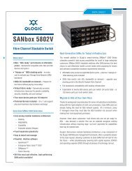
Chapter 1. Product DescriptionFront PanelThe <strong>Dell</strong> <strong>PowerVault</strong> <strong>TL2000</strong> <strong>Tape</strong> <strong>Library</strong> (2U library) <strong>and</strong> the <strong>Dell</strong> <strong>PowerVault</strong><strong>TL4000</strong> <strong>Tape</strong> <strong>Library</strong> (4U library) provide compact, high-capacity, low-costsolutions for simple, unattended data backup. The 4U library houses up to 48 tapecartridges (or 45 <strong>and</strong> an elective 3-slot I/O Station) in a compact 4U form factorwith easy access to cartridges via four removable magazines. The 2U libraryhouses up to 24 tape cartridges (or 23 <strong>and</strong> an elective 1-slot I/O Station) in acompact 2U form factor with easy access to cartridges via two removablemagazines.The <strong>TL2000</strong>/<strong>TL4000</strong> <strong>Library</strong> supports LTO 3 tape drives with these interfaces: aSmall Computer Systems Interface (SCSI), SAS, Fibre Channel interface (FC). LTO 4<strong>and</strong> LTO 5 drives are Serial Attached SCSI interface (SAS), <strong>and</strong> Fibre Channel (FC)only.3 1 2 3Figure 1-1. Front panel of a 2U library8 4 6 754a77ug2391-1
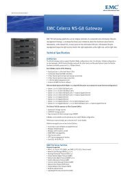
31 2 386 74 5a77ug240Figure 1-2. Front panel of a 4U libraryTable 1-1 below contains front panel descriptions for both the 2U library inFigure 1-1 on page 1-1 <strong>and</strong> the 4U library in Figure 1-2.Table 1-1. 2U library <strong>and</strong> 4U library front panel descriptionsNumber Item Description▌1▐ Power button Pressing this button powers ON the library. Pressing <strong>and</strong> holding this button for 4seconds will power OFF the unit (soft power down). No power switch or button canbe found on the back panel of the library.▌2▐ Front panel v Ready/Activity (Green LED) - It is illuminated any time the unit is powered ON <strong>and</strong>LEDs (left to able to function. It should blink whenever there is library or drive activity, or whenright) the library is in the process of powering up.▌3▐CartridgemagazinesvvvvClean Drive (Amber LED) - It is illuminated when the drive needs to be cleaned.The LED will be turned OFF after the drive is cleaned successfully.Attention (Amber LED) - It is illuminated when there has been a failure thatindicates a piece of media is bad, marginal, or invalid. It will be cleared when allinvalid cartridges have been exported from the library. The amber LED may also belit because a power supply or a power supply fan is failing, or a drive sled isdefective, missing, or has been replaced by a different drive type.Error (Amber LED) - It is illuminated when there is an unrecoverable library ordrive failure. A message is displayed at the same time on the Operator Control Paneldisplay.The 2U library contains two cartridge magazines.– The left magazine can hold up to 12 cartridges (or 11 data cartridges <strong>and</strong> theelective 1-slot I/O Station.)– The right magazine can hold up to 12 cartridges.v The 4U library contains four cartridge magazines.– The upper left magazine can hold up to 12 cartridges.– The lower left magazine can hold up to 12 cartridges (or 9 data cartridges <strong>and</strong> theelective 3-slot I/O Station.)– The upper right magazine can hold up to 12 cartridges.– The lower right magazine can hold up to 12 cartridges.▌4▐ Air vents These vents draw cooler air into the library enclosure <strong>and</strong> allow warm air to escape,which helps keep the library at a normal operating temperature.1-2 <strong>Dell</strong> <strong>PowerVault</strong> <strong>TL2000</strong> <strong>Tape</strong> <strong>Library</strong> <strong>and</strong> <strong>TL4000</strong> <strong>Tape</strong> <strong>Library</strong> User's Guide
Table 1-1. 2U library <strong>and</strong> 4U library front panel descriptions (continued)Number Item Description▌5▐ Control keys v UP (∧) - The upper left button is used to scroll upward through menu items.v DOWN (∨) - The lower left button is used to scroll downward through menu items.v CANCEL (X) - The upper right button is used to cancel a user action <strong>and</strong> return tothe previous menu screen.v SELECT (') - The lower right button is used to display a sub-menu or force anaccessor action.▌7▐ OperatorControl PaneldisplayThis component is a 128 X 64 monochrome graphic display.▌8▐ I/O Station The Input/Output (I/O) Station is used to import <strong>and</strong> export cartridges into <strong>and</strong> outof the library.v The 2U library has an elective 1-slot I/O Station.v The 4U library has an elective 3-slot I/O Station.Rear Panel1 2 3 411 11 10 9875a77ug007Figure 1-3. Rear panel of a 2U library with a SCSI driveChapter 1. Product Description 1-3
1 23 4111098765a77ug100Figure 1-4. Rear panel of a 4U library with full height Fibre Channel drive <strong>and</strong> half height SCSI <strong>and</strong> SAS drives. Theconfiguration shown in this figure is used as an example only. This configuration is not recommended. Half heightSCSI drives are not supported on the <strong>TL2000</strong>/<strong>TL4000</strong>.1 23 41110 9 8 7 65a77ug135Figure 1-5. Rear panel of a 2U library with a full height dual port SAS drive1-4 <strong>Dell</strong> <strong>PowerVault</strong> <strong>TL2000</strong> <strong>Tape</strong> <strong>Library</strong> <strong>and</strong> <strong>TL4000</strong> <strong>Tape</strong> <strong>Library</strong> User's Guide
Table 1-2. 2U library <strong>and</strong> 4U library rear panel descriptionsNumber Item Description▌1▐ Power connector(s) Both libraries require a 110/220 volt AC power connection.v The 2U library has one power supply.v The 4U library has a minimum of one power supply, but has the capability ofadding a redundant power supply.▌2▐ Host interfaceconnectorsThe library has one or more of the following host interface connectors on the drivesled:v a 68-pin HD SCSI connectorv a Fibre Channel connectorv a SFF-8088 mini-SAS connector▌3▐ <strong>Tape</strong> drive sled This library supports the Ultrium 3 <strong>and</strong> Ultrium 4 tape drive. The tape drive in thelibrary is packaged in a container called a drive sled. Drive sleds come in a fullheight or half height configuration. The drive sled is a customer replaceable unit(CRU), <strong>and</strong> is hot-pluggable, which is designed for easy removal <strong>and</strong> replacement.▌4▐Shipping lock <strong>and</strong>label storagelocationThe shipping lock, which secures the accessor during shipping, <strong>and</strong> associatedlabel are stored on the rear panel of the library for future use. See “Removing <strong>and</strong>Storing the Shipping Lock” on page 4-4.Note: The shipping lock must be removed before powering ON the library toallow the accessor to function properly.▌5▐ USB port Used to save/restore library configuration information on a USB device.▌6▐ <strong>Library</strong> ControlBoard (LCC) LEDAn LED showing the status of the <strong>Library</strong> Control Board.LED flashing (1 flash per second) - normal operation▌7▐ Serial port This port is used to communicate serially with the library using an RJ-11 connector.For use by Service Personnel.▌8▐ Ethernet port This port is used to connect the library to a network.LEDv 10/100 Link– Description: Green: Link Integrity– Flashing: Network synchronization/negotiation– Steady (On): Good connection– Off: No connection between NIC <strong>and</strong> hubv Activity– Description: Amber: Port traffic indicator– Flashing: Network traffic present– Steady (On): Heavy network traffic– Off: No traffic▌9▐ <strong>Tape</strong> drive LED This LED indicates the current status of the drive. When the LED is green, itindicates normal drive activity.▌10▐ Service Tag/SerialNumberThe service tag <strong>and</strong> serial number on the pull-out label links the library to yourwarranty.▌11▐ Fan vents These vents allow air to escape from the power supply <strong>and</strong> tape drive sled.Chapter 1. Product Description 1-5
Bar Code ReaderEncryptionThe bar code reader is an integral part of the library accessor. The bar code readerprovides inventory feedback to the host application, Operator Control Paneldisplay, <strong>and</strong> Web User Interface by reading cartridge bar code labels. The librarystores the customized inventory data in memory.<strong>Library</strong> firmware supports a6or8character volume serial number (VOLSER) onthe bar code label on the tape cartridge. Bar code selection is available for librarieswith library code 4.50 or greater.The LTO Ultrium 5 <strong>Tape</strong> Drive supports Application Managed Encryption (AME),<strong>and</strong> <strong>Library</strong> Managed Encryption (LME), using T10 encryption methods, for SAS<strong>and</strong> Fibre Channel drives only. Data encryption is supported with LTO Ultrium 4<strong>and</strong> Ultrium 5 Data Cartridges only. Encryption is also supported with libraryfirmware version 5.80 <strong>and</strong> higher <strong>and</strong> drive firmware version 77BE for LTO 4 <strong>and</strong>higher drive code level.The encryption enabled drive contains the necessary hardware <strong>and</strong> firmware toencrypt <strong>and</strong> decrypt host tape application data. Encryption policy <strong>and</strong> encryptionkeys are provided by the host application or host server. A drive digital certificateis installed at manufacturing time. Each drive receives a unique serial number <strong>and</strong>certificate. The T10 application may validate each drive instance by checking thedrive's digital certificate.CAUTION:The library must be offline from any user <strong>and</strong> all media must beremoved from the drives before license keys are installed or anyconfiguration modifications are made. Please refer to “Power ON/OFF”on page 2-4 <strong>and</strong> “Removing Cartridges from Magazine Slots” on page9-1 for instructions to take the library offline <strong>and</strong> to eject media fromthe drives.To prevent possible data loss due to an EKM server failure, <strong>Dell</strong> recommendsthe use of a primary <strong>and</strong> secondary EKM server. This configuration providesredundancy in the event the primary EKM server is down or unavailable. Pleaserefer to Chapter 2 (Multiple Key Managers for Redundancy) of the <strong>Dell</strong>Encryption Key Manager User's Guide <strong>and</strong> to “Configure <strong>Library</strong>: Encryption”on page 5-47 for information on configuring a primary <strong>and</strong> secondary EKM foryour library.If the backup job fails due to an EKM server failure, the job recovers ifconnectivity is restored to the EKM server prior to expiration of the timeout setin the tape backup software application.Enabling library-managed encryption on a <strong>PowerVault</strong> <strong>TL2000</strong> or <strong>TL4000</strong> is a 6step process.1. Upgrade the library <strong>and</strong> drive firmware to the latest versions. The firmwarecan be found at http://support.dell.com.2. Enable library-managed encryption on the library via the license key if notalready licensed. Please refer to “Configure <strong>Library</strong>: Encryption” on page 5-47for activation instructions.1-6 <strong>Dell</strong> <strong>PowerVault</strong> <strong>TL2000</strong> <strong>Tape</strong> <strong>Library</strong> <strong>and</strong> <strong>TL4000</strong> <strong>Tape</strong> <strong>Library</strong> User's Guide
Supported Internet ProtocolsSNMP MessagingIf you purchased library-managed encryption at the time you purchased yourlibrary, a hard copy of the license key is provided with your library as abackup. If there are any issues with the license key for library-managedencryption purchased with the library, please visit http://www.dell.com/tapeautomation to obtain your license key. You will need the library serialnumber <strong>and</strong> worldwide node name to obtain the license key. Please refer to thefollowing tables in this document for instructions on locating this information:v Table 1.2 for library serial numberv Table 5.6 for library worldwide node nameIf this does not resolve your issue, please contact <strong>Dell</strong> technical support.3. Configure library-managed encryption on your library. Please refer to“Configure <strong>Library</strong>: Encryption” on page 5-47 for instructions.4. Install the <strong>Dell</strong> Encryption Key Manager (EKM) application on the serverdesignated for EKM. Please refer to Chapter 3.0 of the <strong>Dell</strong> Encryption KeyManager User's Guide for instructions. This document can be found athttp://support.dell.com.5. Configure the EKM application. Please refer to Chapter 4.0 of the <strong>Dell</strong>Encryption Key Manager User's Guide for instructions.6. Start the EKM application. Please refer to Chapter 5.0 of the <strong>Dell</strong> Encryption KeyManager User's Guide for instructions.Note: All encryption settings should be configured or re-verified in the drive afterany library or drive reset. This is because a new drive may have been addedor an existing drive may have been swapped with another drive.The library supports the following Internet protocols:v IPv4v IPv6To learn more about Internet protocols, visit http://www.iana.org/.Occasionally, the library may encounter a situation that you want to know about,such as an open magazine or a fault that causes the library to stop. The libraryprovides a st<strong>and</strong>ard TCP/IP protocol called Simple Network Management Protocol(SNMP) to send alerts about conditions (such as need for operator intervention)over a TCP/IP LAN network to an SNMP monitoring station. These alerts arecalled SNMP traps. Using the information supplied in each SNMP trap, themonitoring station (together with customer-supplied software) can alert operationspersonnel of possible problems or operator interventions that occur.SNMP TrapsSNMP traps are alerts or status messages that can be collected, monitored <strong>and</strong>used to proactively manage attached libraries using SNMP protocol with the hostserver(s). In summary, each trap provides the following information:vvProduct Identification such as product name, description, manufacturer, modelnumber, firmware level, <strong>and</strong> the URL that the trap is designated for.Product Status such as the severity of the trap, status (current <strong>and</strong> previous) <strong>and</strong>the time the trap occurred.Chapter 1. Product Description 1-7
vvvv<strong>Library</strong> State (physical device status) such as identification <strong>and</strong> status of devicesthat are monitored. In the case of the library, it would include enclosure, powersupply, controller, magazine status, drive count, cartridge slot count, <strong>and</strong> I/Ostation count. Also included would be certain library statistics, <strong>and</strong> whereappropriate, the fault FSC (fault symptom code) including the severity <strong>and</strong>description of that fault.Drive Status such as the identification of each drive in the library, firmwarelevel, serial number <strong>and</strong> other address <strong>and</strong> status information.Trap Definitions such as library status change, open magazine, I/O accessed,hard fault information, drive cleaning requests, excessive retries <strong>and</strong> libraryreturning to normal operations. For additional information, refer to Appendix G."SNMP Status MIB Variables <strong>and</strong> Traps" on page G-1.SNMP MIBs: The library's Management Information Base (MIB) contains unitsof information that specifically describe an aspect of the system, such as thesystem name, hardware number or communications configuration. Status <strong>and</strong>error data is also gathered by MIBs <strong>and</strong> sent to one or more IP addressesdefined during the SNMP configuration operation. Download the SNMP MIBfile for this library from http://www.support.dell.com.Maximum <strong>Library</strong> Storage Capacity <strong>and</strong> Data Transfer RateMaximum library storage capacity <strong>and</strong> maximum data transfer rates are as follows:Table 1-3. <strong>Tape</strong> drive model <strong>and</strong> host interface type<strong>Tape</strong> Drive ModelHost InterfaceUltrium 5 drives v 8 Gb/s Fibre Channel - single portv6 Gb/s SAS - dual portUltrium 4 Full Height drives v 4 Gb/s Fibre Channel - single portv3 Gb/s Serial Attached SCSI (SAS) - dual portUltrium 4 Half High V2 drives v 8Gb/s Fibre Channel - single portv6GB/s Serial Attached SCSI (SAS) - dual portUltrium 4 Half Height drives v 3 Gb/s SAS - single portUltrium 3 Full Height drives v Ultra160 SCSI LVD (depending on drive; single-ended (SE) is notrecommended as it will severely degrade performance)v 4 Gb/s Fibre Channel - single portUltrium 3 Half High V2 drives v 6GB/s Serial Attached SCSI (SAS) - dual portUltrium 3 Half Height drives v 3 Gb/s SAS - single portTable 1-4. <strong>Library</strong> storage capacity <strong>and</strong> data transfer rateCharacteristic 2U <strong>Library</strong> Specification 4U <strong>Library</strong> SpecificationMaximum storage capacity -Ultrium 5 Data CartridgesMaximum storage capacity -Ultrium 4 Data Cartridgesvvv24 data cartridgesNative: 36 TBCompressed: 72 TB (2:1 compression)v 24 data cartridgesv Native: 19.2 TBv Compressed: 38.4 TB (2:1compression)v 48 data cartridgesv Native: 72 TBv Compressed: 144 TB (2:1compression)v 48 data cartridgesv Native: 38.4 TBv Compressed: 75.2 TB (2:1compression)1-8 <strong>Dell</strong> <strong>PowerVault</strong> <strong>TL2000</strong> <strong>Tape</strong> <strong>Library</strong> <strong>and</strong> <strong>TL4000</strong> <strong>Tape</strong> <strong>Library</strong> User's Guide
Table 1-4. <strong>Library</strong> storage capacity <strong>and</strong> data transfer rate (continued)Characteristic 2U <strong>Library</strong> Specification 4U <strong>Library</strong> SpecificationMaximum storage capacity - v 24 data cartridgesv 48 data cartridgesUltrium 3 Data Cartridgesv Native: 9.6 TBv Native: 19.2 TBSustained native data transferratev Compressed: 19.2 TB (2:1compression)LTO 3 HH: 60 MBs,LTO3 HH V2: 80 MBsLTO3FH:80MBsLTO 4 HH <strong>and</strong> FH: 120 MBsLTO 5 : 140 MBsv Compressed: 38.4 TB (2:1compression)Ultrium <strong>Tape</strong> DrivesThis library supports the Ultrium 3, Ultrium 4, <strong>and</strong> Ultrium 5 <strong>Tape</strong> Drives. Eachtape drive in the library is packaged in a container called a drive sled. The drivesled is a customer replaceable unit (CRU), <strong>and</strong> is designed for quick removal <strong>and</strong>replacement in the library.The Ultrium 5 <strong>Tape</strong> Drive supports two SAS SFF-8088 connectors, or one LC FibreChannel connector. The SFF-8088 SAS connectors on the Ultrium 5 tape drives arecompatible with SAS-1 or SAS-2 cables.The Ultrium 4 Full Height <strong>Tape</strong> Drives support SAS, or Fibre Channel interfaces. Itfeatures two SFF-8088 SAS connectors, or one LC Fibre Channel connector. TheUltrium 4 Half Height <strong>Tape</strong> Drive supports one SAS SFF-8088 connector. TheUltrium 4 Half High V2 <strong>Tape</strong> Drives support two SFF-8088 SAS connectors, or oneLC Fibre Channel connector. The SFF-8088 SAS connectors on the Ultrium 4 tapedrives are compatible with SAS-1 cables.The Ultrium 3 Full Height <strong>Tape</strong> Drive supports LVD Ultra160, or Fibre Channelinterfaces. It features two HD68 connectors or one LC Fibre Channel connector. TheUltrium 3 Half Height Drive supports one SAS SFF-8088 connector. The Ultrium 3Half High V2 <strong>Tape</strong> Drive supports two SFF-8088 SAS connectors. The SFF-8088SAS connectors on the Ultrium 3 tape drives are compatible with SAS-1 cables.Chapter 1. Product Description 1-9
a77ug008Figure 1-6. <strong>Library</strong> drive sled without ESD springs (SCSI sled shown)1a77ug202Figure 1-7. <strong>Library</strong> drive sled with ESD springs [1] (SAS sled shown)Speed MatchingTo improve system performance, the Ultrium 3, Ultrium 4, <strong>and</strong> Ultrium 5 <strong>Tape</strong>Drives use a technique called speed matching to dynamically adjust its native(uncompressed) data rate to the slower data rate of the attached server.Channel CalibrationThe channel calibration feature of the Ultrium 3, Ultrium 4, <strong>and</strong> Ultrium 5 <strong>Tape</strong>Drives customizes each read/write data channel for optimum performance. Thecustomization enables compensation for variations in the recording channeltransfer function, media characteristics, <strong>and</strong> read/write head characteristics.1-10 <strong>Dell</strong> <strong>PowerVault</strong> <strong>TL2000</strong> <strong>Tape</strong> <strong>Library</strong> <strong>and</strong> <strong>TL4000</strong> <strong>Tape</strong> <strong>Library</strong> User's Guide
Power ManagementThe Ultrium 3, Ultrium 4, <strong>and</strong> Ultrium 5 <strong>Tape</strong> Drive's power management functioncontrols the drive's electronics so that part of the electronics completely turn OFFwhen circuit functions are not needed for the drive's operation.Media<strong>Library</strong> SpecificationsThe library uses Ultrium <strong>Tape</strong> Cartridges that provide up to 1500 GB nativecapacity (up to 3000 GB with 2:1 hardware data compression) for LTO 5 tapedrives, up to 800 GB native capacity (up to 1600 GB with 2:1 hardware datacompression) for LTO-4 tape drives, <strong>and</strong> up to 400 GB native capacity (up to 800GB with 2:1 hardware data compression) for LTO-3 tape drives.Ultrium 5 tape drives can read <strong>and</strong> write LTO Ultrium 5 Data Cartridges. Ultrium5 tape drives can read <strong>and</strong> write LTO Ultrium 4 Data Cartridges at originalUltrium 4 capacities, <strong>and</strong> can also read LTO Ultrium 3 Data Cartridges withimproved data rates. Ultrium 4 tape drives can read <strong>and</strong> write LTO Ultrium 4 DataCartridges. Ultrium 4 tape drives can read <strong>and</strong> write LTO Ultrium 3 DataCartridges at original Ultrium 3 capacities, <strong>and</strong> can also read LTO Ultrium 2 DataCartridges with improved data rates. Ultrium 3 <strong>Tape</strong> Drives can read <strong>and</strong> writeLTO Ultrium 3 Data Cartridges. Ultrium 3 <strong>Tape</strong> Drives can read <strong>and</strong> write LTOUltrium 2 Data Cartridges at original Ultrium 2 capacities, <strong>and</strong> can also read LTOUltrium 1 Data Cartridges with improved data rates of up to 20 MB/second nativedata transfer rate (40 MB/second with 2:1 compression). Ultrium 4 tape drivescannot read Ultrium 1 tapes. Ultrium 5 tape drives cannot read Ultrium 1 orUltrium 2 tapes.Supported cartridges include:v LTO Ultrium 1500 GB Data Cartridge (Ultrium 5)v LTO Ultrium 800 GB Data Cartridge (Ultrium 4)v LTO Ultrium 400 GB Data Cartridge (Ultrium 3)v Write-Once-Read-Many WORM Data Cartridge (Ultrium 3, Ultrium 4, Ultrium5)v LTO Ultrium 200 GB Data Cartridge (Ultrium 2)v 100 GB Data Cartridge (Ultrium 1; read only)v LTO Ultrium Cleaning CartridgePhysical SpecificationsTable 1-5. Physical SpecificationsSpecification 2U library 4U libraryRack mount 87.6 mm (3.44 in), Rack mount 175.2 mm (6.9 in),Heightst<strong>and</strong>-alone 97.6 mm (3.84 in) st<strong>and</strong>-alone 185.2 mm (7.3 in)Width 447.5 mm (17.6 in.) 447.5 mm (17.6 in.)DepthRack mount 740 mm (29.13 in),st<strong>and</strong>-alone 810 mm (31.9 in)Rack mount 740 mm (29.13 in),st<strong>and</strong>-alone 810 mm (31.9 in)Weight with 1 drive <strong>and</strong> withoutmedia 15.59 kg (34.37 lbs.) 21.32 kg (47 lbs.)Weight with media 20.67 kg (45.57 lbs.) 31.71 kg (69.9 lbs.)Chapter 1. Product Description 1-11
Power SpecificationsTable 1-6. Power SpecificationsAC power voltage 100-127 VAC; 200-240 VAC (4 - 2 A)Line frequency50-60 HzOperation SpecificationsTable 1-7. Operation Specifications: Ultrium 5<strong>Library</strong> with2U <strong>Library</strong>Ultrium 5 drive(s)Maximum storagecapacityMaximum number of data cartridges: 24Native: 36 TBCompressed: 72 TB (2:1 compression)4U <strong>Library</strong>Maximum number of data cartridges: 48Native: 72 TBCompressed: 144 TB (2:1 compression)Number of slots 24 (including I/O Station) 48 (Including 3 I/O station slots)Sustained nativeUltrium 5 Drive: 140 MB/sdata transfer rateUltrium 5 Drive: 140 MB/sDrive typesUltrium 5 DriveFibre Channel, SASUltrium 5 Drive:Fibre Channel, SASInterfaces8 Gb/s Fibre Channel6 Gb/s SAS*Host Interface Drive Transfer Rates may vary depending on host usage <strong>and</strong> interface utilization.Table 1-8. Operation Specifications: Ultrium 4<strong>Library</strong> with2U <strong>Library</strong>Ultrium 4 drive(s)Maximum storagecapacityMaximum number of data cartridges: 24Native: 19.2 TBCompressed: 38.4 TB (2:1 compression)4U <strong>Library</strong>Maximum number of data cartridges: 48Native: 38.4 TBCompressed: 75.2 TB (2:1 compression)Number of slots 24 (including I/O Station) 48 (Including 3 I/O station slots)Sustained nativedata transfer rateUltrium 4 Full Height Drive: 120 MB/sUltrium 4 Half Height Drive: 120 MB/sDrive typesUltrium 4 Full Height DriveFibre Channel, SASUltrium 4 Half Height Drive: SAS, Fibre ChannelInterfacesUltrium 4 HH Fibre Drive V2 (8Gb/s)Ultrium 4 HH SAS Drive V2 (6Gb/s)4 Gb/s Fibre Channel3 Gb/s SAS*Host Interface Drive Transfer Rates may vary depending on host usage <strong>and</strong> interface utilization.1-12 <strong>Dell</strong> <strong>PowerVault</strong> <strong>TL2000</strong> <strong>Tape</strong> <strong>Library</strong> <strong>and</strong> <strong>TL4000</strong> <strong>Tape</strong> <strong>Library</strong> User's Guide
Table 1-9. Operation Specifications: Ultrium 3<strong>Library</strong> with2U libraryUltrium 3 drive(s)Maximum storagecapacityMaximum number of data cartridges: 24Native: 9.6 TBCompressed: 19.2 TB (2:1 compression)4U libraryMaximum number of data cartridges: 48Native: 19.2 TBCompressed: 38.4 TB (2:1 compression)Number of slots 24 (including I/O Station) 48 (Including 3 I/O station slots.)Sustained nativedata transfer rateDrive typesInterfacesUltrium 3 Full Height Drive: 80 MB/sUltrium 3 Half High V2 Drive: 80 MB/sUltrium 3 Half Height Drive: 60 MB/sUltrium 3 Full HeightDrive: SCSI, Fibre ChannelUltrium 3 Half Height Drive: Serial Attached SCSI (SAS)Ultra160 SCSI LVD4 Gb/s Fibre ChannelUltrium 3 HH SAS Drive V2 (6Gb/s)3 Gb/s SASEnvironmental SpecificationsTable 1-10. Environmental SpecificationsTemperatureOperating 10° to 35° C (50° to 95° F)Storage, without cartridges -30° to 60° C (-22° to 140° F)Wet bulb, operating26° C (79.0° F) maximumTemperature shock immunity - maximum rate of change10° C (18° F) per hourMiscellaneousDust concentrationless than 200 microgram/cubic meterAltitude (operating)2500 meters (8200 ft.) at 25°C ambientMaximum acoustical noise sound power levels LwAd in bels 6.6/6.8HumidityOperating15% to 80% RH non-condensingStorage, without cartridges10% to 90% RH non-condensingProduct EnvironmentThe library is designed to operate in a general business environment.The library meets the acoustical requirements for general business area category2D. Category 2D states that the library should be installed a minimum of 4m(13ft.) from a permanent work station.To allow for service access, install the library a minimum of 0.9 m (3 ft.) from allobstacles.The library is a precision computer peripheral. To ensure maximum longevity ofyour library, locate the library away from dust, dirt, <strong>and</strong> airborne particulates:Chapter 1. Product Description 1-13
Chapter 2. User InterfacesOperator Control PanelThis library has two user interfaces.v Operator Control Panel - located on the front panel of the libraryv “Web User Interface” on page 2-4 - accessed via a web browserThe Operator Control Panel operates in two basic modes.v User Interaction mode - This mode is employed when a user is pushing buttonson the Operator Control Panel.v System Driven mode - This is the normal mode of operation. In this mode, theOperator Control Panel displays status associated with the actions that werecaused from comm<strong>and</strong>s issued via the drive's internal (drive to library) serialinterface.When an Operator Control Panel button is pressed <strong>and</strong> released, the OperatorControl Panel automatically transitions to User Interaction mode. User Interactionmode will continue until 3 minutes after a user stops pushing buttons, or therequested accessor action stops - whichever is longer. At which time, the OperatorControl Panel will return to System Driven mode.If necessary, the Operator Control Panel automatically transitions to the SystemDriven mode. When this occurs, the library must remember the previous functionbefore the display mode changed. Therefore the next button pressed onlytransitions the Operator Control Panel to the User Interaction mode from theSystem Driven mode.In case of the activated user security feature, the User Interaction mode isrestricted to Login <strong>and</strong> Monitor menu items, until a user logs in with a correctpassword.Operator Control Panel PhilosophyOperator Control Panel operation must obey some basic rules. These rules ofoperation constitute a philosophy.vvvAny operational conflict between comm<strong>and</strong>s received over the host interface orthe Web User Interface <strong>and</strong> those entered via the Operator Control Panel will beavoided with a reservation mechanism on a first-come, first-served basis. Anyreservation by the Operator Control Panel is canceled by an Operator ControlPanel logout or a timeout, which cancels the User Interaction Mode.<strong>Library</strong> firmware will not allow a user to select an impossible request. Thosesituations will include, but are not limited to:– Moving a cartridge from any source to a full slot– Moving a cartridge from an empty slot– Loading a cartridge from any source to a full drive– Unloading a cartridge from an empty driveAny error detected by the library or drive controller <strong>and</strong> not recoverable throughpredetermined firmware algorithms will be considered as fatal. An error codewill be displayed on the Operator Control Panel display <strong>and</strong> the error LED will2-1
vbecome illuminated. The error code remains on the Operator Control Panel untila push button is pressed, which causes the Operator Control Panel to return tothe Home Screen.Numeric error codes are only used for unrecoverable, fatal errors, otherwise textstatus messages are displayed.Power-ON DisplayWhen the library powers ON or resets, it goes through several internally controlledprocesses that allow it to get initialized <strong>and</strong> running. These processes are calledPower-On-Self-Test (POST). During the POST the Operator Control Panel displaysinformation that may be meaningless until POST is complete. When the POST isfinished, the library displays the Startup screen, then the Home screen.The Startup screen is the first screen that appears after powering ON the library. Itcontains the following information:v Firmware Rev: the current level of library firmwarev Drives: the total number of drives that the library can supportv Magazines: the total number of magazines in the libraryv I/O Station: the current status of the I/O StationWhile the library is going through its power up cycle you can monitor the state ofthe library via the OCP; however, you may not be able to make any configurationchanges until the unit has completed its initialization routine. Attempts to makechanges will be ignored.Firmware Rev: 120RDrive: 1Magazines: 2I/O Station: emptyIdle R<strong>and</strong>omStartup<strong>TL4000</strong>Figure 2-1. Power-ON screensAccessor Drive 1 2Idle R<strong>and</strong>Note about the Front Panel LEDsAll LEDs are updated during power ON <strong>and</strong> reset sequences. Upon power ON orsoftware reset, the library illuminates all LEDs as soon as POST allows. Wheninitialization starts, all LEDs are extinguished <strong>and</strong> the Ready/Activity LED flashesat a rate of approximately one second per cycle. When the mechanical initializationis complete, the Ready/Activity LED will stop flashing <strong>and</strong> be constantlyilluminated.If a library failure occurs, the Ready/Activity LED will turn OFF <strong>and</strong> the ErrorLED illuminates. The Operator Control Panel will also display an appropriate errorcode to help identify the failure.2-2 <strong>Dell</strong> <strong>PowerVault</strong> <strong>TL2000</strong> <strong>Tape</strong> <strong>Library</strong> <strong>and</strong> <strong>TL4000</strong> <strong>Tape</strong> <strong>Library</strong> User's Guidea77ug187
3. As soon as the Operator Control Panel display shows the correct value, pressthe SELECT button to apply the value.Toggling ValuesToggle values are used to switch between two different states like ON <strong>and</strong> OFF.1. After navigating to the menu item, press the SELECT button to select the menuitem.2. Using the UP <strong>and</strong> DOWN buttons, select one of the various predefined statesfor that item.3. Press the SELECT button to apply the new state.Entering Numerical ValuesNumerical values are needed for network addresses, password entries <strong>and</strong> otherconfiguration entries.1. After navigating to the menu item, the current value is displayed <strong>and</strong> thecursor highlights the first digit of the value that can be changed.2. For each digit to be changed in the value:a. Use the UP <strong>and</strong> DOWN buttons to increment / decrement the digit.b. Press the SELECT button to highlight the next editable digit.3. Press the SELECT button at the last digit to apply the complete entry, or pressthe CANCEL button to cancel the whole edit process <strong>and</strong> maintain the originalvalue.Power ON/OFFPart of the Operator Control Panel is the Power ON/OFF button. If the library ispowered ON, pressing this button for 4 seconds will initiate a controlled powerdown of the library (soft l<strong>and</strong>ing). The following operations will take place beforethe library shuts down completely:vvvvWeb User InterfaceThe display indicates with an appropriate message that the shutdown is inprogress.The library controller finishes all ongoing library <strong>and</strong> drive activities.The accessor is moved to its home position.The library controller switches OFF the power supply's secondary side.Note: The shutdown process may be aborted by releasing the button before 4seconds has passed.Many of the same operations performed from the Operator Control Panel can alsobe performed remotely using the Web User Interface.The Web User Interface lets you monitor <strong>and</strong> control your library from anyterminal connected to your network or through the World Wide Web (WWW). TheWeb User Interface hosts a dedicated, protected Internet site that displays agraphical representation of your library.For static IP Addresses only: After establishing a connection to the library, openany HTML browser <strong>and</strong> enter the IP address of the library. To configure the Web2-4 <strong>Dell</strong> <strong>PowerVault</strong> <strong>TL2000</strong> <strong>Tape</strong> <strong>Library</strong> <strong>and</strong> <strong>TL4000</strong> <strong>Tape</strong> <strong>Library</strong> User's Guide
User Interface, you must first set the IP address using the Operator Control Panel.Refer to "Configure: Network" on page 5-23 or "Configure <strong>Library</strong>: Network" onpage 5-45.LoginImportant: Some options of the Web User Interface take the library OFFLINE. Thisinactive mode can interfere with host-based application software,causing data loss. Make sure the library is idle before attempting toperform any remote operations that will take the library OFFLINE.To login, select the Role type <strong>and</strong> enter the correct password. The <strong>TL4000</strong>/<strong>TL2000</strong>RMU screen shows Welcome : User, superuser, admin, or service after a successfullogin. The user can log out at any time by clicking on the "logout" text located into top right corner of the RMU page.vvvvThe User only has access to Monitor <strong>Library</strong> menus.The User account has onlyviewing privileges to the unit, not able to make any configuration changes.Superuser - The Superuser has access to the Monitor <strong>Library</strong> <strong>and</strong> Manage<strong>Library</strong> sections.The Admin user has access to all menus except those restricted to Serviceonly.The Admin account has access to monitor, configure <strong>and</strong> run unitdiagnostics (only exception is the advanced diagnostics reserved for servicepersonnel only).Service personnel have access to all menus. The Service account has all thesame privileges as the Admin account with the addition of advanced unitdiagnostics.Note: User <strong>and</strong> Superuser accounts must be enabled by the libraryadministrator. These accounts are disabled by default.Note: Passwords are case-sensitive.Use the following password for logging in as an Admin user: secureEach level affects which areas you have access to <strong>and</strong> what actions you can initiatefrom those areas.For DHCP, use the Operator Control Panel to determine the IP Address assigned toyour library. Navigate to Monitor → <strong>Library</strong> → Identity. Scroll down to IP Address<strong>and</strong> make note of the address. Enter the IP Address in your internet browseraddress field to access your library with the Web User Interface.For IPv4 or Dual Stack IPv4 + IPv6, enter your library's static IP Address using the0.0.0.0 format (four octets).For IPv6, enter your library's static IP Address or Router Assigned IP Addressusing the following format: http://[0:0:0:0:0:0:0:0]. To determine your RouterAssigned IP Address, navigate to Monitor → <strong>Library</strong> → Network on the OperatorControl Panel.If the dual IP stack is enabled (IPv4 + IPv6), IPv6 addresses cannot be configuredin the OCP (Operator Control Panel) <strong>and</strong> must be configured through the WebUser Interface. IPv6 addresses can only be configured in the OCP if the IPv6-onlystack is enabled. In the case where the dual stack is enabled, the IPv6 address mustbe configured through the web interface (either using the IPv4 address or a knownChapter 2. User Interfaces 2-5
other IPv6 address).a77ug070Figure 2-2. Web User Interface login pageSystem StatusThe System Status screen is always present after login giving current status of thelibrary.a77ug080Figure 2-3. 2U library System Status screena77ug089Figure 2-4. 4U library System Status screenStatus icons indicate the following conditions.v The green check mark indicates that the library is fully operational <strong>and</strong> that nouser intervention is required.v The yellow exclamation point indicates that user intervention is necessary, butthat the library is still capable of performing operations. This condition can becaused by a media, library, redundant power supply, power supply fan, or adrive sled problem. To determine which, view the System Status screen.v The red X indicates that user intervention is required <strong>and</strong> that the library is notcapable of performing operations.2-6 <strong>Dell</strong> <strong>PowerVault</strong> <strong>TL2000</strong> <strong>Tape</strong> <strong>Library</strong> <strong>and</strong> <strong>TL4000</strong> <strong>Tape</strong> <strong>Library</strong> User's Guide
vIf Auto Clean is enabled <strong>and</strong> a cleaning cartridge is not present, or if a cleaningcartridge is present, but not in a reserved slot, Auto Clean status will show ChkMedia/Rsvd Slot? <strong>and</strong> Status will show a green check mark <strong>and</strong> the wordsMedia Attention. The Auto Clean status disappears from the system statusscreen once Auto Clean has been properly configured. You will get messages ifthe cleaning media expires.Figure 2-5. 4U library System Status screen showing media attention statusvThe Power Supply Status will only appear if redundant power is being utilizedwith a 4U library, <strong>and</strong> the library was manufactured after March 14, 2008. If aredundant power supply fails, the System Status screen will appear as shown inFigure 2-6.Figure 2-6. 4U library System Status screen showing a power supply failureNote: If your library has -04 level redundant power supplies (see label on top ofpower supply), it is normal for the one in “St<strong>and</strong>by” mode to turn its“Green” LED off. You can test this power supply by pulling the powerconnector from the other “Active” power supply. The power supply thatwas in “St<strong>and</strong>by” mode will now become “Active”, <strong>and</strong> its “Green” LEDshould light. If it doesn’t, replace it (refer to “Replacing a Power Supply”on page 10-10).Chapter 2. User Interfaces 2-7
If your library has -05 level redundant power supplies, the "Green" LEDwill be ON on both power supplies. If both "Green" LEDs are not ON,replace the failed power supply (refer to “Replacing a Power Supply” onpage 10-10).Web User Interface Help PagesEach screen on the Web User Interface has an associated Help page. To access aHelp page, click on Help in the upper right corner of the screen. A new web pagewill open. Using the left navigation pane, select the desired Help page. To close theHelp page, click the red X in the upper right corner of the screen.Logging out of the Web User InterfaceTo log out of the Web User Interface, click Logout in the upper right corner of thecurrent screen.Important: If you click the X in the upper right corner of your internet browserwindow, you will not log out of the Web User Interface.2-8 <strong>Dell</strong> <strong>PowerVault</strong> <strong>TL2000</strong> <strong>Tape</strong> <strong>Library</strong> <strong>and</strong> <strong>TL4000</strong> <strong>Tape</strong> <strong>Library</strong> User's Guide
Chapter 3. Installation PlanningBefore installing your library, take time to review the following information.Determining the Number of Logical LibrariesYou can partition the library into as many logical libraries as there are drives in thelibrary.Basic GuidelinesvvvEach logical library must contain at least one drive.A library configuration of exactly one logical library equals the entire physicallibrary.The library issues a warning to the user if media is moved across logicallibraries.<strong>Library</strong> SharingThe library's default configuration allows a single application to operate the librarythrough a single control path. Often, it is advantageous to be able to share a singlelibrary between heterogeneous (dissimilar) or homogeneous (similar) applications.Some applications (<strong>and</strong> some servers) do not allow for sharing a library betweensystems. Configurations can be created that enable the library to processcomm<strong>and</strong>s from multiple heterogeneous applications <strong>and</strong> multiple homogeneousapplications.From the library's Web User Interface or Operator Control Panel, the followingactions can be performed:vvConfigure the library so that it is partitioned into separate logical libraries thatindependently communicate with separate applications through separate controlpaths. This configuration requires no special capabilities from the server orapplication. (For more information, see “Using Multiple Logical Libraries for<strong>Library</strong> Sharing” on page 3-2.)Configure any single logical library (including the entire physical library) so thatit is shared by two or more servers that are running the same application.Depending on the capabilities of the server <strong>and</strong> application, there are severalways to set up this type of configuration. Three typical ways include:– Configuring one server (host) to communicate with the library through asingle control path; all other servers send requests to that server through anetwork.– Configuring all of the servers to communicate with the library through asingle, common control path. This configuration is used in high-availabilityenvironments. Multi-initiator configurations are only supported by certainadapters <strong>and</strong> independent software vendors (ISVs). Check with your ISV.– Configuring a single logical library to communicate with multiple serversthrough multiple control paths. This configuration requires that control pathsbe added (see “Using Multiple Control Paths” on page 3-2).<strong>Library</strong> configuration is not limited to the examples given above. Manyconfigurations are possible, <strong>and</strong> can be designed according to your business needs.For additional information, refer to your host application documentation.3-1
Using Multiple Logical Libraries for <strong>Library</strong> SharingMultiple logical libraries are an effective way for the library to simultaneously backup <strong>and</strong> restore data from heterogeneous applications. For example, the library canbe partitioned so that it processes:Using Multiple Control Pathsv Comm<strong>and</strong>s from Application A (about Department X) in Logical <strong>Library</strong> 1v Comm<strong>and</strong>s from Application B (about Department Y) in Logical <strong>Library</strong> 2In this configuration, the storage slots <strong>and</strong> drives in each logical library arededicated to that library <strong>and</strong> are not shared among other libraries. Comm<strong>and</strong>sissued by the applications travel to the library through two unique control paths.Thus, the data processing for:v Department X is confined to the storage slots <strong>and</strong> drives in Logical <strong>Library</strong> 1v Department Y is confined to the storage slots <strong>and</strong> drives in Logical <strong>Library</strong> 2In addition to creating multiple logical libraries, any logical library can beconfigured to have more than one control path. When configuring additionalcontrol paths, additional library sharing configurations <strong>and</strong> availability options aremade possible. Access to the logical library is on a first-come, first-served basis <strong>and</strong>each control path for a logical library can accept comm<strong>and</strong>s while the library is inuse by another control path. By default, only the first drive in a logical library willbe LUN-1 enabled.For a particular logical library, you can enable as many control paths as there aredrives in that logical library.Using Multiple Control Paths for Path FailoverComm<strong>and</strong> failures <strong>and</strong> timeouts are costly. You want your library to run smoothly<strong>and</strong> efficiently. To ensure continued processing, the library offers an optional pathfailover feature that enables the host device driver to resend the comm<strong>and</strong> to analternate control path for the same logical library. With control path failoverinstalled, the alternate control path can include another HBA, SAN, or librarycontrol path drive. The device driver initiates error recovery <strong>and</strong> continues theoperation on the alternate control path without interrupting the application.Path Failover is a combination of two previous features: Control Path Failover (keyentered at the library user interface) <strong>and</strong> Data Path Failover (key entered at thedevice driver interface). For library firmware of 8.xx or lower the Path Failoverfeature is available for LTO 4 tape drives. <strong>Library</strong> firmware levels higher than 8.xxsupport Path Failover on LTO 5 drives, as well as LTO 4 Full Height drives.The Path Failover feature can be installed by the customer.For more information about using the path failover feature, see the <strong>Dell</strong> <strong>PowerVault</strong><strong>TL4000</strong> Failover Configuration Guide, included with the library documentation ifpurchased at point of sale <strong>and</strong> with the customer kit if purchased later.<strong>Library</strong> Partitioning <strong>and</strong> Element Addressing<strong>Library</strong> 4U systems with firmware versions of .80 <strong>and</strong> higher, <strong>and</strong> containing atleast 2 drives, have the ability to configure two logical libraries (create twopartitions). This partitioning has been exp<strong>and</strong>ed with the new library firmware <strong>and</strong>half-high drive integration. Now it is possible to configure 1, 2, 3 or 4 partitions in3-2 <strong>Dell</strong> <strong>PowerVault</strong> <strong>TL2000</strong> <strong>Tape</strong> <strong>Library</strong> <strong>and</strong> <strong>TL4000</strong> <strong>Tape</strong> <strong>Library</strong> User's Guide
the 4U library. Additionally the 2U library can now be configured into one or twopartitions. Each library must contain at least one drive per logical library(partition). In a partitioned library, the Operator Control Panel (OCP) only reportsthe status of logical library 1 in the main menu due to space limitations. The usermust navigate to the logical libraries status in the OCP to get the information onthe additional library partitions.Partitioning of 2U LibrariesWhen two half height drives are installed in a 2U library, the library firmware willsupport partitioning in the same way that the 4U supports partitioning with twofull height drives today. The first partition will contain the first magazine <strong>and</strong> thefirst drive. The second partition will contain the second magazine <strong>and</strong> the seconddrive. The I/O station (if configured as I/O) will be shared, as is done with thepartitioned 4U library.One full height drive is "Drive 1". When using half height drives, the first halfheight drive position will be called "Drive 1", The second half height drive positionwill be called "Drive 2."Partitioning of 4U LibrariesWhen one or more half height drives are added to a 4U library, the drive namingwill change. Currently, the first full height drive is "Drive 1" <strong>and</strong> the second fullheight drive is "Drive 2". When you consider that each full height drive slot maycontain one or two half height drives, there are four potential drives in the spacethat used to occupy two. As a result, the first half height drive position, or the firstfull-high drive position, will be called "Drive 1". The second half height driveposition will be called "Drive 2". The third half height drive position, or the secondfull height drive position, will be called "Drive 3". The fourth half height driveposition will be called "Drive 4".Important: In a 4U library a full height drive sled may be installed in drive slot 1(drive will occupy slot 1 <strong>and</strong> slot 2) or drive slot 3 (drive will occupyslot 3 <strong>and</strong> slot 4). A full height drive sled should never be installed indrive slot 2 (drive will occupy slot 2 <strong>and</strong> slot 3).Mixing of DrivesThe library supports a mix of full height <strong>and</strong> half height drives in the samephysical library <strong>and</strong> the same logical library. They support a mix of Gen 3, Gen 4,<strong>and</strong> Gen 5 drives in the same physical library <strong>and</strong> the same logical library. Theywill also support a mix of SCSI, SAS, <strong>and</strong> Fibre Channel in the same physicallibrary <strong>and</strong> the same logical library; however, mixing drive interface types in thesame logical library is not recommended.Configuration of a 1 - Partition SystemA one partition system configured for a 4U library contains any <strong>and</strong> all drivespresent in any drive positions, <strong>and</strong> it will contain all four magazines.When configured with one logical partition, the Element Address assignments willbe as follows: DTE assignments will be as shown in Figure 3-1 on page 3-4.STE assignments:Chapter 3. Installation Planning 3-3
vLogical <strong>Library</strong> 1: Slot1 through 23 4096 (0x1000) through 4118 (0x1016) asshown in Figure 3-4 on page 3-5Drive 2Element Address257Drive 1Element Address256Drive 4Element Address259Drive 3Element Address258Drive 1Element Address256Drive 3Element Address258Drive 2Element Address257Drive 1Element Address256Drive 4Element Address259Drive 3Element Address258Drive 2Element Address257Drive 1Element Address256Magazine2Magazine1Front sideMagazine4Magazine3a77ug161Figure 3-1. Configuration of a one - partition systemConfiguration of a 2 - Partition SystemA two partition system must have at least two drives installed. One drive must beinstalled in either drive position 1 or drive position 2, <strong>and</strong> another drive must beinstalled in either drive position 3 or drive position 4. Partition 1 contains anydrives in drive position 1 <strong>and</strong> drive position 2. Partition 1 will also containmagazine 1 <strong>and</strong> magazine 2. Partition 2 contains any drives in drive position 3 <strong>and</strong>drive position 4. Partition 2 will also contain magazine 3 <strong>and</strong> magazine 4.When configured with two logical partitions, the Element Address assignmentswill be as follows: DTE assignments will be as shown in Figure 3-2.STE assignmentsv Logical <strong>Library</strong> 1: Slot 1 through slot 21 4096 (x1000) through 4116 (0x1014)v Logical <strong>Library</strong> 2: Slot 22 through slot 45 4096 (x1000) through 4019 (0x1017)Drive 2Element Address256Drive 1Element Address256Drive 4Element Address257Drive 3Element Address256Drive 1Element Address256Drive 3Element Address256Drive 2Element Address257Drive 1Element Address256Drive 4Element Address257Drive 3Element Address256Drive 2Element Address257Drive 1Element Address256Magazine2Magazine1Front sideMagazine4Magazine3a77ug162Figure 3-2. Configuration of a two - partition systemConfiguration of a 3 - Partition SystemA three partition system must have at least three drives installed. A drive must beinstalled in drive position 1, another drive must be installed in drive position 2,<strong>and</strong> another drive must be installed in either drive position 3 or drive position 4.Partition 1 will contain the first drive <strong>and</strong> the first magazine. Partition 2 willcontain the second drive <strong>and</strong> the second magazine. Partition 3 will contain anydrives in drive position 3 <strong>and</strong> drive position 4. Partition 3 will also containmagazine 3 <strong>and</strong> magazine 4.STE assignmentsv Logical <strong>Library</strong> 1: Slot 1 through slot 9 4096 (x1000) through 4104 (0x1008)3-4 <strong>Dell</strong> <strong>PowerVault</strong> <strong>TL2000</strong> <strong>Tape</strong> <strong>Library</strong> <strong>and</strong> <strong>TL4000</strong> <strong>Tape</strong> <strong>Library</strong> User's Guide
vvLogical <strong>Library</strong> 2: Slot 10 through slot 21 4096 (x1000) through 4107 (0x100B)Logical <strong>Library</strong> 3: Slot 22 through slot 45 4096 (x1000) through 4119 (0x1017)Drive 3Element Address256Drive 2Element Address256Drive 1Element Address256Drive 4Element Address257Drive 3Element Address256Drive 2Element Address256Drive 1Element Address256Magazine2Magazine1Front sideMagazine4Magazine3a77ug163Figure 3-3. Configuration of a three - partition systemConfiguration of a 4 - Partition SystemA four partition system must have four drives. Each partition contains one drive<strong>and</strong> one magazine.When configured with four logical partitions, the Element Address assignmentswill be as follows: DTE assignments will be as shown in Figure 3-4.STE assignmentsv Logical <strong>Library</strong> 1: Slot 1 through slot 9 4096 (x1000) through 4104 (0x1008)v Logical <strong>Library</strong> 2: Slot 10 through slot 21 4096 (x1000) through 4107 (0x100B)v Logical <strong>Library</strong> 3: Slot 22 through slot 33 4096 (x1000) through 4107 (0x100B)v Logical <strong>Library</strong> 4: Slot 34 through slot 45 4096 (x1000) through 4107 (0x100B)Drive 4Element Address256Drive 3Element Address256Drive 2Element Address256Drive 1Element Address256Magazine2Magazine1Front sideMagazine4Magazine3a77ug164Figure 3-4. Configuration of a four - partition systemSCSI Element AddressingEvery logical library starts at the first drive slot with the current assigned elementstart address (default value 256). It will be incremented from the bottom to the topslots for every drive slot. There is one exception to this addressing scheme toaccommodate libraries currently in the field. A 4U library containing only fullheight drives will continue to have the addresses assignments 256 <strong>and</strong> 257, thuscausing no interruptions to their operation. Drive slots will still be incremented by1 for each drive slot position.Note: Exchanging drives with different form factors will result in the libraryneeding to be reconfigured.Chapter 3. Installation Planning 3-5
4U Unit with only FH drives(1 logical library)SCSI Element257256Slot43214U Unit with FH <strong>and</strong> HH drives(1 logical library)SCSI Element258257256Figure 3-5. Examples of SCSI element addressingSlot4321a77ug165The SCSI specification does not allow gaps in the SCSI element addressing. Specialh<strong>and</strong>ling is needed for empty drive slots to fulfill the specification. Alsotemporarily removed drives need to have their addresses preserved to not confusethe attached host <strong>and</strong> host application. Generally only drives which are currentlyphysically available or temporarily removed are reported. Empty (unused) slotslocated at the bottom or the top should not be reported, with an exception in caseof a “removed” condition. A drive slot which does not contain a drive, <strong>and</strong> has aposition between used slots, needs to be reported as a SCSI element. To signal thehost application that this slot is not usable, its ACCESS bit will be disabled.Note: When reducing the number of drives in your library, update the Logical<strong>Library</strong> configuration. This will remove the Attention LED on the frontpanel <strong>and</strong> the exclamation mark on the Home screen indicating that a driveis missing.Updating the Logical <strong>Library</strong> configuration will also update the drive elementaddressing <strong>and</strong> drive numbering. Replacing LTO half height drives with full heightdrives may require you to execute Restore Factory Defaults to correctly update thedrive element addressing <strong>and</strong> drive numbering. See “Configure <strong>Library</strong>:Save/Restore Configuration” on page 5-56.Logical Unit Number (LUN) ScanningThe library uses a single SCSI or Loop ID per drive <strong>and</strong> dual LUNs to control thetape drive (LUN 0) <strong>and</strong> library accessor (LUN 1). The library requires a Host BusAdapter (HBA) that supports LUN scanning. If it is not enabled, your host systemwill not scan beyond LUN 0 <strong>and</strong> will fail to discover the library. It will only seethe tape drive.Important: Some HBAs, such as RAID controllers, do not support LUN scanning.3-6 <strong>Dell</strong> <strong>PowerVault</strong> <strong>TL2000</strong> <strong>Tape</strong> <strong>Library</strong> <strong>and</strong> <strong>TL4000</strong> <strong>Tape</strong> <strong>Library</strong> User's Guide
Host InterfacesThe 2U library <strong>and</strong> the 4U library can be attached to servers using the followinginterfaces:v SCSI (LVD Ultrium 160)v Serial Attached SCSI (SAS)v Fibre ChannelTable 3-1. Host Drive Interface SupportDrive SCSI (LVD Ultra 160) SAS FCUltrium 3 FH X XUltrium 3 HHXUltrium 4 FH X* XUltrium 4 HHXNote: * = Dual Port SASSCSI InterfaceNote: Although the LVD hardware in the library is capable of operating insingle-ended (SE) mode, SE operation is not recommended.The library supports SCSI LVD attachments by using SCSI cables with 68-pin,HD-connectors. SCSI adapters must be properly terminated.Before installing the SCSI cables, inspect all cables for damage. Do not install acable if it is damaged. Report the damage immediately by contacting <strong>Dell</strong> customercare.The maximum allowable length of your bus cabling depends on the type of SCSIbus that you use (LVD).v For a server with an LVD SCSI bus:– Use a maximum system-to-device cable length of 10 m (33 ft) when attachingto the host interface board (SCSI) <strong>and</strong> one or two daisy-chained drives.– Use a maximum system-to-device cable length of 5 m (17 ft) when attachingto the host interface board (SCSI) <strong>and</strong> three to six daisy-chained drives.Note: For maximum performance, it is recommended to have a maximum ofone drive per SCSI bus.– Only use the maximum system-to-device cable length of 25 m (82 ft) whenattaching directly to one device (a point to point interconnection).Note: Daisy-chaining is NOT recommended due to potential issues with SCSIbus performance, SCSI cables/connectors, <strong>and</strong> host bus adapters.Physical Characteristics of the SCSI InterfaceThe library operates as a set of SCSI-3 devices. The Ultrium <strong>Tape</strong> Drives attach toservers using an LVD Ultra160 SCSI interface. Each SCSI drive sled uses shielded,HD68-pin connectors, <strong>and</strong> can attach directly to a 2-byte-wide SCSI cable.Any combination of up to two initiators (servers) <strong>and</strong> up to four targets (devices)is allowed on a single SCSI bus if the following conditions are met:Chapter 3. Installation Planning 3-7
vvThe SCSI bus is terminated properly at each endCable restrictions are followed according to the SCSI-3 specificationUnder the SCSI-3 protocol, this type of attachment allows cable lengths of up to 25m (81 ft) with the appropriate cable <strong>and</strong> terminator. The table below gives themaximum bus length between terminators for the LVD interface.Table 3-2. Maximum bus length between terminatorsMaximum Bus Length Between Terminators (inType of Interconnectionmeters)Point-to-point (1 server <strong>and</strong> 1 drive) 25Multi-drop/daisy-chain (1 server <strong>and</strong>12 (LVD)multiple drives)Note: The maximum bus lengths stated in this table include the internal length of the bus.For maximum performance, multiple SCSI buses may be required (see “UsingMultiple SCSI Buses”), <strong>and</strong> Ultrium <strong>Tape</strong> Drives must be the only target devicesthat are active on the bus.Note: Daisy-chaining is NOT recommended due to potential issues with SCSI busperformance, SCSI cables/connectors, <strong>and</strong> host bus adapters.Note: For maximum performance, the quantity of tape drives that you can attachto one SCSI bus is limited, <strong>and</strong> is based on the type of bus that you have<strong>and</strong> the amount of data compression achieved. Ultra160 SCSI buses have ab<strong>and</strong>width of 160 MB per second. The table below lists the types of SCSIbuses <strong>and</strong> gives the recommended maximum quantity of drives that you canattach.Table 3-3. Recommended maximum quantity of drives per SCSI busType of DriveLVD Ultrium 3Ultra 160 SCSI Bus1 drive at 2:1 compressionUsing Multiple SCSI BusesThe library has two SCSI connectors for each tape drive in the library. Each drivecan be daisy-chained using a SCSI bus jumper.Note: Daisy-chaining is NOT recommended due to potential issues with SCSI busperformance, SCSI cables/connectors, <strong>and</strong> host bus adapters.Removal of any jumpers will create a SCSI bus for each drive installed in yourlibrary for attachment to multiple servers or to multiple SCSI adapter cards on oneserver. Remember that each SCSI bus must be terminated. Multiple SCSI busesmay be required for maximum performance, depending on the application <strong>and</strong>data compression ratio. Note, however, that library (Medium Changer) control isrequired on at least one SCSI bus.The Medium Changer device is required to be addressed via LUN 1 of thelowest-numbered drive position of each logical library. The Medium Changerdevice may additionally be addressed via LUN 1 of other drives in any logicallibrary.3-8 <strong>Dell</strong> <strong>PowerVault</strong> <strong>TL2000</strong> <strong>Tape</strong> <strong>Library</strong> <strong>and</strong> <strong>TL4000</strong> <strong>Tape</strong> <strong>Library</strong> User's Guide
Any bus containing a Medium Changer device via LUN 1 of a drive is referred toas a control <strong>and</strong> data path. Any other bus is referred to as a data path. Forinformation about control paths, see “Using Multiple Control Paths” on page 3-2.Terminating the BusThe SCSI bus <strong>and</strong> all of the wires in the SCSI cable must be properly terminatedaccording to the SCSI st<strong>and</strong>ard.You can plug an external terminator into one of the SCSI connectors. A terminatormust be installed on the last device on each end of a string of multiple devices. Aterminator is included with each SCSI Ultrium <strong>Tape</strong> Drive.SCSI Differential - LVDLVD tape devices support a bus length of 25 meters (82 ft.) point-to-point, <strong>and</strong> 12meters (39 ft.) using multi-drop interconnection (daisy-chaining). For eachdaisy-chained device, the maximum cable length must be reduced by 0.5 meters(1.6 ft).Important: A faster bus does not imply that an attached device will support thatdata rate, but that multiple devices can operate on the bus at thatmaximum speed. For a detailed table of SCSI terms <strong>and</strong> relatedspecifications, refer to the SCSI Trade Association Web site athttp://www.scsita.org/terms/scsiterms.html. To ensure bestperformance, if possible, avoid daisy-chaining.SAS InterfaceA drive sled with a SAS (Serial Attached SCSI) interface can be linked directly tocontrollers. SAS is a performance improvement over traditional SCSI because SASenables multiple devices (up to 128) of different sizes <strong>and</strong> types to be connectedsimultaneously with thinner <strong>and</strong> longer cables; its full-duplex signal transmissionsupports up to 6.0 Gb/s. The SFF-8088 SAS connectors on the Ultrium 5 tapedrives are compatible with SAS-1 or SAS-2 cables. The SFF-8088 SAS connectors onthe Ultrium 3 <strong>and</strong> Ultrium 4 tape drives are compatible with SAS-1 cables. Inaddition, SAS drives can be hot-plugged.SAS drives will auto-negotiate speed. There are no configurable topologies thus nofeature switches associated with SAS. The SAS Ultrium 3 <strong>and</strong> Ultrium 4 half heightdrive sleds are single ported <strong>and</strong> can only be attached to one host. The Ultrium 4full height <strong>and</strong> Ultrium 5 drives are dual ported, <strong>and</strong> can be attached to amaximum of two hosts. The intention of the second port is for redundancy; forfailover rather than sharing. Sharing between these two hosts is limited toactive/passive cluster failover. LAN-free drive sharing is not supported. Ultrium 3<strong>and</strong> Ultrium 4 SAS drive sleds use the SFF-8088 connection at the drive sled end<strong>and</strong> SFF-8088 or SFF-8470 at the host adapter end.Fibre Channel InterfaceFibre Channel allows for an active intelligent interconnection scheme, called aFabric, to connect devices. Everything between the ports on Fibre Channel is calledthe Fabric. The Fabric is most often a switch or series of switches that takes theresponsibility for routing.The library allows the selection of the following Fibre channel port behaviors:v LN Port: (default setting) - an automatic configuration that tries arbitrated loopfirst, then switched fabricv L Port - arbitrated loopChapter 3. Installation Planning 3-9
vN Port - point to point protocol in a switched fabric topologyCables <strong>and</strong> SpeedsUltrium 3, Ultrium 4, <strong>and</strong> Ultrium 5 Fibre Channel tape drives use LC duplex fiberoptics cables.The maximum distances that the library supports on a Fibre Channel link isdetermined by the link speed, the type of fiber (50-micron or 62.5-micron), <strong>and</strong> thedevice to which the library is attached.If the library attaches to an HBA (Host Bus Adapter), refer to the distances that aresupported by the HBA. If the library attaches to a switch, the supported distancesare:v For a multi-mode 50-micron cable:– 1-Gbit link speed = up to 500 m (1640 ft)– 2-Gbit link speed = up to 300 m (984 ft)– 4-Gbit link speed = up to 175 m (574 ft)– 8-Gbit link speed = up to 150 m (492 ft)v For a multi-mode 62.5-micron cable:– 1-Gbit link speed = up to 300 m (984 ft)– 2-Gbit link speed = up to 90 m (295 ft)– 4-Gbit link speed = up to 50 m (164 ft)– 8-Gbit link speed = up to 21 m (68 ft)Note: Minimum distance for both 50 micron <strong>and</strong> 62.5 micron is 2m(6ft).The library uses 50-micron cables internally. Therefore, you must use a 50-microncable to attach to the library's port. To attach to a 62.5-micron SAN, you mustattach the 50-micron cable to an active port, such as a port on a switch.Using Zoning to Isolate Devices <strong>and</strong> Enhance SecurityFor security reasons, it is important to limit the devices that a server or servers canrecognize or access. Also, some performance configurations <strong>and</strong> SANconfigurations can result in a device being seen multiple times from the sameserver. For example, if you have two HBAs from the same server connected to anUltrium <strong>Tape</strong> Drive in the library, the drive will be detected <strong>and</strong> appear as twological devices. That is, there will be two special files for one physical device.Zoning can address these issues.Zoning allows you to partition your SAN into logical groupings of devices so thateach group is isolated from the other <strong>and</strong> can only access the devices in its owngroup. Two types of zoning exist: hardware zoning <strong>and</strong> software zoning. Hardwarezoning is based on physical fabric port number. Software zoning is defined with aWorld Wide Node Name (WWNN) or World Wide Port Name (WWPN). Whilezoning can be reconfigured without causing an outage, some zoning configurationscan become complicated. The advantage of the library's WWNN implementation isthat you can avoid the exposure of introducing zoning errors because you do nothave to change the zoning configuration if a drive needs service or replacement.Sharing on a Storage Area NetworkWith Storage Area Network (SAN) components, the possibilities for connectingmultiple systems <strong>and</strong> multiple drives have increased. Not all software <strong>and</strong> systemsare designed to share drives. Before you install a drive that would allow twosystems to share it, check that the systems <strong>and</strong> their software support sharing. If3-10 <strong>Dell</strong> <strong>PowerVault</strong> <strong>TL2000</strong> <strong>Tape</strong> <strong>Library</strong> <strong>and</strong> <strong>TL4000</strong> <strong>Tape</strong> <strong>Library</strong> User's Guide
your software does not support sharing, note that Fibre Channel switches have azoning capability to form a SAN partition. For systems that do not cooperate, usezoning to prevent the systems from sharing the same drive. You can remove zonedpartitions as you upgrade software <strong>and</strong> system levels.Chapter 3. Installation Planning 3-11
3-12 <strong>Dell</strong> <strong>PowerVault</strong> <strong>TL2000</strong> <strong>Tape</strong> <strong>Library</strong> <strong>and</strong> <strong>TL4000</strong> <strong>Tape</strong> <strong>Library</strong> User's Guide
Chapter 4. Installation <strong>and</strong> ConfigurationNote: Review the information in "Installation Planning" before installing yourlibrary.To install a desktop or rack mounted 2U library or 4U library, perform theprocedures in this chapter in the order they are presented.Using the <strong>Library</strong> Configuration FormInstalling Your <strong>Library</strong>Before beginning the installation <strong>and</strong> configuration of your library, make a copy ofthe Appendix G, “<strong>Library</strong> Configuration Form,” on page G-1. Enter libraryinformation (such as serial numbers, types of drives, etc.) <strong>and</strong> configurationsettings on the <strong>Library</strong> Configuration Form <strong>and</strong> store in a safe location for futurereference. Be sure to update this form any time changes are made to your libraryhardware or configuration.Complete these procedures to install your library hardware.1. “Choosing a Location.”2. “Unpacking the <strong>Library</strong>” on page 4-2.3. “Verifying the Shipment” on page 4-2.4. “Installing the <strong>Library</strong> Foot Pads (for Desktop Installation ONLY)” on page 4-3.5. “Removing <strong>and</strong> Storing the Shipping Lock” on page 4-4.6. “Rackmounting the <strong>Library</strong> (for Rack Installation ONLY)” on page 4-6.7. .8. “Connecting the Host Interface Cable” on page 4-11.9. “Connecting a Power Cord” on page 4-13.Choosing a LocationChoose a location that meets the following criteria:Table 4-1. Location criteriaCriteriaDefinitionRoom temperature 10° - 35° C (50° - 95° F )Note: If the temperature in the room where the library will be installed varies by 15° C (30°F) from the room where the library was stored, allow the library to acclimate to thesurrounding environment for at least 12 hours before unpacking it from the shippingcontainer.Power source v AC power voltage: 100-127 VAC; 200-240 VAC (4 - 2 A)Note: The 4U library requires two separate power sources to implement redundantpower.v Line frequency: 50-60 HzPlace the library near an AC outlet. The AC power cord is the product's main ACdisconnect device <strong>and</strong> must be easily accessible at all times. Two separate power sourcesmust be available for redundant power.4-1
Table 4-1. Location criteria (continued)CriteriaAir qualityHumidityDefinitionThe library should be placed in an area with minimal sources of particulate contamination.Avoid areas near frequently used doors <strong>and</strong> walkways, stacks of supplies that collect dust,printers, <strong>and</strong> smoke-filled rooms. Excessive dust <strong>and</strong> debris can damage tapes <strong>and</strong> tapedrives.15-80 % RH non-condensingClearance v Back: Minimum of 15.4 cm (6 inches)Rack requirementsv Front: Minimum of 30.8 cm (12 inches)v Sides: Minimum of 5.08 cm (2 inches)St<strong>and</strong>ard 19-inch rack with:v 2U (88.90 mm/3.5 in.) of clearance for a 2U libraryv 4U (177.8 mm/7 in.) of clearance for a 4U libraryRackmounting the library is optional.Unpacking the <strong>Library</strong>Note: If the temperature in the room where the library will be installed varies by15° C (30° F) from the room where the library was stored, allow the libraryto acclimate to the surrounding environment for at least 12 hours beforeunpacking it from the shipping container.1. Before you begin, clear a work surface to unpack the library.2. Before opening <strong>and</strong> removing the library from the shipping container, inspectthe container for shipping damage. If you notice any damage, report it to theshipping company immediately.3. Open the shipping container <strong>and</strong> carefully remove the shipping materials fromthe top of the library. Remove the accessory package <strong>and</strong> set it aside.Important: Once the drive is unpacked, save <strong>and</strong> store the packaging materialsfor future moves or shipping.4. Lift the library out of the carton <strong>and</strong> remove the bag from the library. Removethe foam cushion from the back of the library. Save the packaging materials forfuture use.Important: Do not place the library on the front panel or the rear panel as thismay damage the library.Verifying the ShipmentVerify that the following items are included in your library shipment:vvvWith every library:– Power cord– Bar code labels– Foot pads (for desktop installation)With every library containing a SCSI drive:– SCSI terminator (one per SCSI drive)– SCSI library-to-host cable (if ordered by customer)With every library containing a Fibre Channel drive:– Fibre Channel library-to-host/switch cable (if ordered by customer)4-2 <strong>Dell</strong> <strong>PowerVault</strong> <strong>TL2000</strong> <strong>Tape</strong> <strong>Library</strong> <strong>and</strong> <strong>TL4000</strong> <strong>Tape</strong> <strong>Library</strong> User's Guide
vvWith every library containing a SAS drive:– SAS library-to-host cable (if ordered by customer)Rack Mount KitInstalling the <strong>Library</strong> Foot Pads (for Desktop InstallationONLY)If you intend to install your library in a rack, skip this step <strong>and</strong> proceed to“Removing <strong>and</strong> Storing the Shipping Lock” on page 4-4.Important: Operating your library on a flat surface without foot pads may damageyour library or cause it not to function properly.Six foot pads must be installed on the bottom of the library before the library canbe used as a desktop unit.To install the library foot pads:1. Being very careful, lay the library on its side.2. Peel the adhesive from the back of each foot pad.3. Install the foot pads on the bottom of the library enclosure by pressing eachfoot into one of the six areas (▌1▐) as shown in the figure below.Chapter 4. Installation <strong>and</strong> Configuration 4-3
1a77ug085Figure 4-1. Installing foot pads on the bottom of the library enclosure4. Carefully return the library to an upright position.Important: Do not place any objects on top of the library.Removing <strong>and</strong> Storing the Shipping LockImportant: The shipping lock, which prevents the library accessor from movingduring shipment, must be removed before the library is powered ON.The shipping lock is held in place with a label <strong>and</strong> is located in the top center ofthe library. After the shipping lock is removed, it should be stored on the right sideof the back panel of the library for future use.To remove <strong>and</strong> store the shipping lock:1. Remove the blue label ( 2 ) that is securing the lock ( 1 ) to the top of thelibrary, then remove the lock (see Figure 4-2 on page 4-5).4-4 <strong>Dell</strong> <strong>PowerVault</strong> <strong>TL2000</strong> <strong>Tape</strong> <strong>Library</strong> <strong>and</strong> <strong>TL4000</strong> <strong>Tape</strong> <strong>Library</strong> User's Guide
12a77ug018Figure 4-2. Shipping lock <strong>and</strong> label2. Store the lock ( 1 ) <strong>and</strong> label ( 2 ) on the rear panel of the library as shown inFigure 4-3.12a77ug019Figure 4-3. <strong>Library</strong> shipping lock <strong>and</strong> label storage locationChapter 4. Installation <strong>and</strong> Configuration 4-5
Rackmounting the <strong>Library</strong> (for Rack Installation ONLY)The 2U library <strong>and</strong> the 4U library are easily installed into a st<strong>and</strong>ard 19-inch racksystem. The 2U library requires 2U (3.5 in.) of space. The 4U library requires 4U (7in.) of space.If you are not rackmounting your library, skip this procedure <strong>and</strong> go to “Attachingthe <strong>Library</strong> to a Server” on page 4-11.Important: A 2U library weighs 15.59 kg (34.37 lbs.) with one drive <strong>and</strong> withoutmedia. A 4U library weighs 21.32 kg (47 lbs.) with one drive <strong>and</strong>without media.To reduce the risk of personal injury or damage to the library:1. observe local health <strong>and</strong> safety requirements <strong>and</strong> guidelines formanual material h<strong>and</strong>ling,2. obtain adequate assistance to lift <strong>and</strong> stabilize the library duringinstallation or removal, <strong>and</strong>3. always remove all cartridges to reduce the overall weight of thelibrary.To install your library in a rack, perform the following steps.1. Verify that your rack kit includes the following contents (see Figure 4-4 on page4-7):v Packaged in plastic material:– 2 rails (not shown)– 2 mounting brackets (▌1▐)v Packaged in the small bag with no label:– 1 Torx wrench (▌5▐)– 2 anchors (▌4▐)– 2 countersunk screws for securing the anchors (▌6▐)– 2 small countersunk screws for securing the tops of the mounting brackets(▌7▐)– 2 large screws to secure the mounting brackets to the rack (▌8▐)v Packaged in the small bag with "Round Hole" on the label: 9 screws to beused on racks with round holes. (▌2▐)v Packaged in the small bag with "Square Hole" on the label: 9 screws to beused on racks with square holes. (▌3▐)4-6 <strong>Dell</strong> <strong>PowerVault</strong> <strong>TL2000</strong> <strong>Tape</strong> <strong>Library</strong> <strong>and</strong> <strong>TL4000</strong> <strong>Tape</strong> <strong>Library</strong> User's Guide
Figure 4-4. Rack Kit mounting hardware2. Determine the location in your rack for your library to be installed <strong>and</strong>, using apencil, mark the location on each vertical rail in your rack.Note: A 2U library requires 2U (3.5 in.) of rack space. A 4U library requires 4U(7 in.) of rack space.1 321 42a77ug133Figure 4-5. Examples of EIA units for round hole <strong>and</strong> square hole installations▌1▐ Two EIA units for round hole <strong>and</strong> ▌3▐ Wide Gaps within the EIA unit▌2▐ square hole installation▌4▐ Narrow Gaps between EIA unitsChapter 4. Installation <strong>and</strong> Configuration 4-7
3. Using the screws for your rack type (round holes or square holes) <strong>and</strong> a #2Phillips screwdriver <strong>and</strong> ensuring that the flange on each rail points toward theother to form a shelf, secure one rail to each side of the rack in your chosenrack location. Secure both the front <strong>and</strong> back of each rail to the rack. Thenarrow end of each rail goes to the rear of the rack. The rails extend to fit avariety of rack depths. Each rail requires 2U of rack space (▌1▐ in Figure 4-6).1a77ug009Figure 4-6. Rear view of a rack showing the narrow part of the rail4. Using the Torx wrench included in your shipment, remove the screws ( 1 )asshown in Figure 4-7. Screw locations on the 4U library are similar.1a77ug011Figure 4-7. 2U library side screws to remove5. Install the library rack anchors (▌2▐) as shown in Figure 4-8 on page 4-9 oneach side of your library using the longest counter-sunk screws included in therack kit.4-8 <strong>Dell</strong> <strong>PowerVault</strong> <strong>TL2000</strong> <strong>Tape</strong> <strong>Library</strong> <strong>and</strong> <strong>TL4000</strong> <strong>Tape</strong> <strong>Library</strong> User's Guide
1 2a77ug012Figure 4-8. 2U library rack anchors <strong>and</strong> mounting brackets6. Install the library mounting brackets (▌1▐) as shown on the 2U library on eachside of the library using the screw that was removed from your library <strong>and</strong> anadditional short, counter-sunk screw included in the rack kit. (The 4U rackanchors <strong>and</strong> mounting brackets are similar.)7. With library rack anchors <strong>and</strong> mounting brackets installed, slide the libraryonto the rails (as shown in Figure 4-9 <strong>and</strong> Figure 4-10 on page 4-10). When thelibrary stops, gently push the library to lock the anchors installed on each sideof the library to the rails <strong>and</strong> until the mounting brackets are flush with thevertical rack rails.a77ug127Figure 4-9. Sliding the 2U library into the rackChapter 4. Installation <strong>and</strong> Configuration 4-9
a77ug109Figure 4-10. Sliding the 4U library into the rack8. Using a #2 Phillips screwdriver, secure the library to the rack (see Figure 4-11for a 2U library; see Figure 4-12 on page 4-11 for a 4U library) by placing ascrew in the center hole of each mounting bracket <strong>and</strong> tightening them ( 1 ).1a77ug128Figure 4-11. Securing the 2U library to the rack4-10 <strong>Dell</strong> <strong>PowerVault</strong> <strong>TL2000</strong> <strong>Tape</strong> <strong>Library</strong> <strong>and</strong> <strong>TL4000</strong> <strong>Tape</strong> <strong>Library</strong> User's Guide
1a77ug110Figure 4-12. Securing the 4U library to the rackAttaching the <strong>Library</strong> to a ServerThe 2U library <strong>and</strong> the 4U library can be attached to servers using the followinginterfaces:v SCSI (LVD Ultra 160)v Fibre Channelv Serial Attached SCSI (SAS)Connecting the Host Interface CableTo connect the host interface cables to the library:1. It is recommended that you shut down <strong>and</strong> turn OFF the associated server.Turn OFF all attached devices. Remove the power cables from the server <strong>and</strong>all attached accessories.Important: Failure to remove the power cords from these devices beforeconnecting the host interface cable could result in damage to thelibrary.2. For a SCSI library, attach one end of the host interface cable to one of theconnectors on the back panel of the library (see ▌1▐ in Figure 4-13 on page4-12). For a Fibre Channel library, attach one end of the host interface cable tothe connector on the back panel of the library (see ▌5▐ in Figure 4-14 on page4-12). For a Serial Attached SCSI (SAS) connected library, attach the host end ofthe SAS cable to the SAS HBA (see ▌2▐ in Figure 4-15 on page 4-12). Full highdrives will have dual SAS connectors. Half high drives will have one SASChapter 4. Installation <strong>and</strong> Configuration 4-11
connector. Unused SAS connectors do not need to be terminated.1a77ug0174 32Figure 4-13. Attaching a SCSI host interface cable to the 2U library4a77ug10161 32 5Figure 4-14. Attaching host interface cables to the 4U library. THE CONFIGURATION SHOWN IN THIS FIGURE ISUSED FOR EXAMPLE ONLY. THIS CONFIGURATION IS NOT SUPPORTED.1 23a77ug134Figure 4-15. Attaching a SAS interface cable to the 2U library3. Attach the other end of the host interface cable as follows:v For a SCSI library, connect the host interface cable to the connector on theSCSI host bus adapter or to the connector on the previous device on the SCSIbus. Attach the terminator ( 3 in Figure 4-13) to the remaining SCSIconnector on the back panel of the library, if the library is the last or only4-12 <strong>Dell</strong> <strong>PowerVault</strong> <strong>TL2000</strong> <strong>Tape</strong> <strong>Library</strong> <strong>and</strong> <strong>TL4000</strong> <strong>Tape</strong> <strong>Library</strong> User's Guide
vdevice on the SCSI bus. Otherwise, attach one end of a SCSI cable to theremaining port <strong>and</strong> the other end to the next device on the SCSI bus. Makesure that the last device on the SCSI bus is properly terminated.Note: Only cables <strong>and</strong> terminators specified for Ultra160 or Ultra320 use orlabeled as Multi Mode should be used.Note: The host bus adapter should be LVD SCSI. A single-ended (SE) SCSIhost bus adapter will work, but will severely degrade performance,<strong>and</strong> limit cable length. If there are any SE devices on the same SCSIbus, the entire SCSI bus will negotiate down to SE speed <strong>and</strong> severelydegrade performance.For a Fibre Channel library, connect the host interface cable to the host or toa switch.v For a SAS library, connect the Host Interface Cable to the host HBA, using adirect SFF-8088 connection, or an interposer as required. Unused SASconnectors do not need termination.4. Plug the network ethernet cable 2 in Figure 4-13 on page 4-12, Figure 4-14 onpage 4-12), or ▌3▐ in Figure 4-15 on page 4-12 into the ethernet port on the backpanel of the library. If the ethernet connection is directly attached to a server orlaptop, a crossover ethernet cable may be required.Note: It is the customer's responsibility to supply the crossover cable if one isrequired.Connecting a Power CordAttention: This product can ONLY be used with an approved power cord foryour specific geographic region. Use of an unapproved power cord may result in:v not meeting individual country specific safety requirements;v overheating with potential personal injury <strong>and</strong>/or property damage; <strong>and</strong>v a fracture resulting in the internal contacts being exposed, which potentiallycould subject the user to a shock hazard.For every power supply in the library, complete the following steps.1. Remove the protective label from the power receptacle on your library.a77ug197Figure 4-16. Removing the protective label from the power receptacleChapter 4. Installation <strong>and</strong> Configuration 4-13
Configuring Your <strong>Library</strong>2. Plug one end of the power cord (▌6▐ in “Connecting the Host Interface Cable”on page 4-11) into each power supply connector on the back panel of thelibrary.3. Plug the other end of each power cord into the nearest properly groundedpower outlet. Use separate power sources for each power supply for redundantpower.Attention: To disconnect all power from the library, remove the power cordfrom each outlet. The power button removes power from portions of the library<strong>and</strong> the drives, but the power supplies still have AC power at their inputs.4. Remove the protective plastic on the exterior surfaces of the library.5. Turn ON the library using the power button. Check the Operator Control Paneldisplay to make sure the library is receiving power. If it is not, check the powerconnections <strong>and</strong> your power source. During the Power-On Self Test (POST), allfour LEDs are illuminated briefly, followed by a flashing Ready LED. When theinitialization sequence is complete, the Home screen will be displayed.Note: Review the information in "Installation Planning" before configuring yourlibrary.The library can be configured using the Operator Control Panel <strong>and</strong>/or the WebUser Interface. The recommended method for configuring your library is using theWeb User Interface.Choosing Your Configuration MethodIf you choose to use the factory defaults for your library configuration, go to“Using Factory Defaults as Your Configuration.”If you choose to use the Web User Interface for configuring your library, go to“Configuring Your <strong>Library</strong> using the Web User Interface” on page 4-15.If you choose to use the Operator Control Panel for configuring your library, go to“Configuring Your <strong>Library</strong> using the Operator Control Panel” on page 4-31.Write down all library configuration settings on the Appendix G, “<strong>Library</strong>Configuration Form,” on page G-1 for future reference.Using Factory Defaults as Your ConfigurationThe table below shows the main default library settings. If you wish to use thedefaults, no other changes need to be made before using your libraryItemDefault SettingLogical Libraries 1Active SlotsMaximumI/O SlotsEnabledDHCPEnabledInternet ProtocolIPv4 OnlyBar Code Label Length 8<strong>Library</strong> ModeR<strong>and</strong>om4-14 <strong>Dell</strong> <strong>PowerVault</strong> <strong>TL2000</strong> <strong>Tape</strong> <strong>Library</strong> <strong>and</strong> <strong>TL4000</strong> <strong>Tape</strong> <strong>Library</strong> User's Guide
ItemAutoCleanEncryptionDefault SettingDisabledApplication Managed Encryption (AME)For a full list of factory defaults, see “Configure: Save/Restore” on page 5-27.Configuring Your <strong>Library</strong> using the Web User InterfaceTo configure your library using the Web User Interface, complete the followingprocedures:1. “Establishing Remote Access to Your <strong>Library</strong>”2. “Logging on to the Web User Interface” on page 4-173. “Verifying/Updating Firmware” on page 4-184. “Choosing General <strong>Library</strong> Settings” on page 4-195. “Choosing the Number of Logical Libraries for Your <strong>Library</strong>” on page 4-206. “Entering Path Failover Feature Activation Key” on page 4-217. “Setting Up Encryption” on page 4-228. “Choosing Drive(s) Interface Identification/Settings” on page 4-249. “Entering <strong>Library</strong> Network Settings” on page 4-2410. “Entering User Access Information using the Web User Interface” on page4-2611. “Entering Date <strong>and</strong> Time using the Web User Interface” on page 4-2812. “Configuring Logs <strong>and</strong> Traces using the Web User Interface” on page 4-2813. “Entering Email Notification Information using the Web User Interface” onpage 4-2914. “Configuring SNMP Settings” on page 4-2915. “Testing Encryption Configuration for <strong>Library</strong> Managed Encryption” on page4-3016. “Restoring Factory Default Settings using the Web User Interface” on page4-3117. “Logging out of the Web User Interface” on page 2-818. “Setting the Operator Control Panel Access PIN using the Operator ControlPanel” on page 5-26Establishing Remote Access to Your <strong>Library</strong>Static library network settings must be entered using the Operator Control Panelbefore the library can be accessed remotely using the Web User Interface. If yoursystem is serviced by DHCP (Dynamic Host Configuration Protocol) server, thenetwork parameters will be automatically set. Once remote access has beenestablished, you can complete the configuration of your library using the Web UserInterface.1. Access the Configure menu using the Operator Control Panel.a. From the screen that shows the library logo (Home screen), press either theUP or DOWN button to get to the Main Menu.b. Press the DOWN button to select Configure.c. Press the SELECT button to display the Configure menu.2. Press the DOWN button to highlight the Network menu.3. Press the SELECT button to display the Network screen.Chapter 4. Installation <strong>and</strong> Configuration 4-15
4. Select IP STACK, <strong>and</strong> press the SELECT button to highlight the InternetProtocol field.a. Press the DOWN or UP button to scroll through the Internet Protocoloptions.b. Press the SELECT button on the desired Internet Protocol.If you select IPv6 protocol, the Configure Network menu will include optionsfor Stateless Autoconfig <strong>and</strong> Prefix length.v Stateless Autoconfig:– Press the DOWN button to highlight Stateless Autoconfig.– Press the SELECT button to highlight the Stateless Autoconfig optionfield.– Press the DOWN button to scroll through the Stateless Autoconfigoptions.– Press the SELECT button to apply the option.v Prefix Length:– Press the DOWN button to highlight Prefix Length.– Press the SELECT button to highlight the Prefix Length option field.– Press the UP or DOWN buttons to scroll through the Prefix Lengthdigits.– Press the SELECT button to apply the Prefix Length digits.5. If you do not want to select DHCP as your library network setting, skip thisstep <strong>and</strong> proceed to the next step. If you want to select DHCP as your librarynetwork setting, complete the following steps:a. Press the DOWN button to highlight DHCP.b. Press the SELECT button to highlight the DHCP field.c. Press the DOWN button to select ON.d. Press the SELECT button to apply your selection.e. Skip to Step 7.6. Press the DOWN button to select IP Address. For IPv4 only, enter only anIPv4 address. For IPv6 only, enter only an IPv6 address. For IPv4 & IPv6,enter an IPv4 address <strong>and</strong> an IPv6 address.a. Press the SELECT button to highlight the IP Address field.b. Press the UP or DOWN button to select the digit(s) in the first octet ofyour library's IP Address.c. Press the SELECT button to highlight the digit(s)in the next octet of yourIP Address.d. After entering the digits for the last octet, press the SELECT button toapply your entries.7. Press the DOWN button to select Netmask. For IPv4, enter only an IPv4Netmask address. For IPv6, enter only an IPv6 Netmask address. For IPv4 &IPv6, enter both IPv4 <strong>and</strong> IPv6 Netmask addresses.a. Press the SELECT button to highlight the Netmask field.b. Press the UP or DOWN button to select the digit(s) in the first octet ofyour library's Netmask address.c. Press the SELECT button to highlight the digit(s) in the next octet of yourlibrary's Netmask address.d. After entering the digits for the last octet of your Netmask address, pressthe SELECT button to apply your entries.4-16 <strong>Dell</strong> <strong>PowerVault</strong> <strong>TL2000</strong> <strong>Tape</strong> <strong>Library</strong> <strong>and</strong> <strong>TL4000</strong> <strong>Tape</strong> <strong>Library</strong> User's Guide
8. Press the DOWN button to select Gateway. For IPv4, enter only an IPv4Gateway address. For IPv6, enter only an IPv6 Gateway address. For IPv4 &IPv6, enter a Gateway address for both IPv4 <strong>and</strong> IPv6.a. Press the SELECT button to highlight the Gateway field.b. Press the UP or DOWN button to select the digit(s) in the first octet ofyour library's Gateway address.c. Press the SELECT button to highlight the digit(s) in the next octet of yourlibrary's Gateway address.d. After entering the digits for the last octet in your Gateway address, pressthe SELECT button to apply your entries.9. Press the DOWN button to select Ethernet.a. Press the DOWN button to highlight the Ethernet field.b. Press the SELECT button to highlight the Ethernet setting.c. Press the DOWN button to select a new setting.d. Press the SELECT button to apply the new setting.10. Press the DOWN button to highlight SAVE. Press the DOWN again tohighlight CANCEL. Continue to press the DOWN button to switch betweenSAVE <strong>and</strong> CANCEL.vvIf SAVE is highlighted, press the SELECT button to apply your newconfiguration. If changes were made to the Network settings, a pop-upmenu will display the option to reboot the library or cancel the reboot. Ifyou select CANCEL in the pop-up menu, you will need to power cycle thelibrary for the network changes to be applied.If CANCEL is highlighted, press the SELECT button to cancel all of yourentries <strong>and</strong> return to the Configure menu.Logging on to the Web User InterfaceTo complete the configuration of your library using the Web User Interface, followthe steps below.1. On your host computer, open an Internet browser.2. In the browser address field, enter your library's IP Address.a. For DHCP <strong>and</strong>/or Stateless Autoconfig, use the Operator Control Panel todetermine the IP Address assigned to your library. Navigate to Monitor →<strong>Library</strong> → Network. Scroll down to the library address information <strong>and</strong>make note of the address. Enter the IP Address in your internet browseraddress field to access your library with the Web User Interface. The libraryaddress information may include one or more of the following addresstypes:v IP Address (IPv4 static or DHCP)v Static IPv6 Addressv Link Local IPv6 Addressv Assigned IPv6 address (DHCP or Stateless Autoconfig)b. For IPv4, enter your library's IP Address using the 0.0.0.0 format (fouroctets).c. For IPv6, enter your library's IP Address using the following format:http://[0:0:0:0:0:0:0:0].d. For Dual Stack IPv4 + IPv6, enter your library's IP Address for either IPv4or IPv6.3. When the login screen appears,Chapter 4. Installation <strong>and</strong> Configuration 4-17
a. Select admin for a User ID.b. Enter secure for a Password.a77ug070Figure 4-17. Log in screen on the Web User InterfaceVerifying/Updating FirmwareIt is important to run the latest level of firmware. To ensure that you are runningthe latest levels of library firmware, drive firmware, <strong>and</strong> SNMP MIB (ManagementInformation Base) file, complete this procedure.1. Verify the SNMP MIB file currently installed on your SNMP server. Verify thelevels of library <strong>and</strong> drive firmware currently installed on your library bycompleting the following steps:a. Exp<strong>and</strong> Monitor <strong>Library</strong> in the left navigation pane of the Web UserInterface.b. Click <strong>Library</strong> Identity <strong>and</strong> make note of the Firmware revision.c. Click Drive Identity <strong>and</strong> make note of the Firmware revision.d. Log out of the Web User Interface.Note: The SNMP MIB file is an optional feature.2. Download the latest library firmware, drive firmware, <strong>and</strong> SNMP MIB(Management Information Base) file from http://support.dell.com.Note: The SNMP MIB file is an optional feature.a. Enter in your internet browser address field <strong>and</strong> press Enter on yourkeyboard.b. Compare the firmware level available on the web to those that you madenote of in step 1. If you are running the latest levels of library <strong>and</strong> drivefirmware, proceed to the next step. If you are not running the latest levelsof library <strong>and</strong> drive firmware, download the firmware that needs to beupdated to your library host.3. Update library <strong>and</strong> drive firmware on your library, if necessary.a. Enter the IP Address of your library in your internet browser address field<strong>and</strong> press Enter on your keyboard.b. Log in to your library's Web User Interface.c. Exp<strong>and</strong> Service <strong>Library</strong> in the left navigation pane of the Web UserInterface.d. Click Upgrade Firmware.e. Browse to the new firmware level on your host, then click Update. Do thisfor both library <strong>and</strong> drive firmware, if necessary.4. Install the MIB file on your SNMP server. Refer to your server applicationdocumentation for instructions.4-18 <strong>Dell</strong> <strong>PowerVault</strong> <strong>TL2000</strong> <strong>Tape</strong> <strong>Library</strong> <strong>and</strong> <strong>TL4000</strong> <strong>Tape</strong> <strong>Library</strong> User's Guide
Choosing General <strong>Library</strong> SettingsIf your library contains only one drive or logical library, both general <strong>and</strong> specificsettings will be combined into one table (see Figure 4-18 on page 4-20).1. Exp<strong>and</strong> Configure <strong>Library</strong> in the left navigation pane of the Web UserInterface.2. Click General <strong>and</strong> enter the following:v <strong>Library</strong> Name - Enter a name for your library.v <strong>Library</strong> Mode (select one of the following per logical library):– R<strong>and</strong>om: In r<strong>and</strong>om mode, the library allows the server's (host's)application software to select any data cartridge in any order.– Sequential: In sequential mode, the library's firmware predefines theselection of the cartridges. After initialization, the firmware causes thelibrary to select the first available cartridge found (counting from the I/OStation through the last slot in your library) for loading into the drive.vImportant: If a Logical <strong>Library</strong> in Sequential Mode contains more thanone drive, only the first drive in the Logical <strong>Library</strong> will beutilized.- Autoload: Sequential mode with autoload mode ON loads the firstavailable cartridge (slot with the lowest numerical value that contains acartridge) automatically if the library powers ON with an empty drive.- Loop: Sequential mode with loop mode ON loads the cartridge in thelowest numerical slot after the cartridge in the highest numerical slothas been filled <strong>and</strong> sent back to its home slot. This allows endlessbackup operations without user interaction.Active Slots - Select the number of active slots you would like to assign inyour library. This item will affect the number of Res. (Reserved) Slots inyour library. For more information refer to “Configuring I/O Stations <strong>and</strong>Reserving Slots” on page 5-65.Note: Slots can be reserved so that they are invisible to the host. It may benecessary to reserve slots in order to match the number of availableslots to the ISV software licensing. Slots will be reserved starting withthe highest element address. If your library does not have a dedicatedcleaning cartridge slot, <strong>and</strong> you desire to enable Auto Clean, you mustdesignate a reserved slot which can be used to hold the cleaningcartridge.v I/O Station Enabled - If checked, the I/O Station is enabled. If not, the first 3slots (in a 4U library or the 1st slot in a 2U library) are configured as storage..v Auto Clean Enabled - Automatically cleans drive when drive requestscleaning <strong>and</strong> cleaning cartridge is present in a reserved slot or a dedicatedcleaning slot. All cleaning cartridges must have CLN as part of the bar code.The Universal Cleaning Cartridge has the bar code label CLNUxxLx.v Bar Code Label Length Reported to Host - Choose between 6 <strong>and</strong> 8. With 6,the first six characters of the cartridge VOLSER (Volume Serial Numbers)will be reported to the host. With 8, All characters in the VOLSER (first sixcharacters plus the two character media type identifier) will be reported tothe host. For more information on bar code labels, see “Bar Code Label” onpage 6-4.v Click one of the following:Chapter 4. Installation <strong>and</strong> Configuration 4-19
– Refresh - Click this button to update the current screen.– Apply Selections - Click this button to submit the changes made to thescreen.Figure 4-18. The 2U library Configure <strong>Library</strong>: General screenFigure 4-19. Example: The 4U library Configure <strong>Library</strong>: General screen3. If your library has more than one drive, proceed to “Choosing the Number ofLogical Libraries for Your <strong>Library</strong>.” If your library has one drive, proceed to“Entering Path Failover Feature Activation Key” on page 4-21.Choosing the Number of Logical Libraries for Your <strong>Library</strong>Note: Review the information in “Determining the Number of Logical Libraries”on page 3-1 before completing the procedure in this section.If you have a 2U or 4U library with only one drive, or do not wish to partitionyour library, proceed to the next section, “Entering Path Failover FeatureActivation Key” on page 4-21.4-20 <strong>Dell</strong> <strong>PowerVault</strong> <strong>TL2000</strong> <strong>Tape</strong> <strong>Library</strong> <strong>and</strong> <strong>TL4000</strong> <strong>Tape</strong> <strong>Library</strong> User's Guide
One cartridge magazine cannot be assigned to two logical libraries. If you partitiona multi-drive library, each of the magazines must be assigned to a logical libraryon a magazine boundary. The entire magazine must be part of one logical libraryonly.Note: If you have a 2U library with two drives, you have the capability to havetwo logical libraries.In a fully populated 4U library with four half height drives <strong>and</strong> four logicallibraries, resource assignments will be as follows:v Logical <strong>Library</strong> 1 will contain Drive 1 <strong>and</strong> the lower left cartridge magazine.v Logical <strong>Library</strong> 2 will contain Drive 2 <strong>and</strong> the upper left cartridge magazine.v Logical <strong>Library</strong> 3 will contain Drive 3 <strong>and</strong> the lower right cartridge magazine.v Logical <strong>Library</strong> 4 will contain Drive 4 <strong>and</strong> the upper right cartridge magazine.The I/O Station <strong>and</strong> slots reserved for cleaning cartridges, if any, are shared amongall logical libraries.1. Click Configure <strong>Library</strong> → Logical Libraries in the left navigation pane.a77ug098Figure 4-20. The 4U library Configure <strong>Library</strong>: Logical Libraries page2. Select the number of logical libraries you would like to create in your library.3. Click Submit to create the logical libraries.Entering Path Failover Feature Activation KeyFor more information, refer to the <strong>Dell</strong> <strong>PowerVault</strong> <strong>TL4000</strong> Failover ConfigurationGuide, included with the library documentation.1. Click Configure <strong>Library</strong> → Path Failover in the left navigation pane.a77ug117Figure 4-21. The Configure <strong>Library</strong>: Path Failover Feature Activation screen2. Enter the Control Path Failover 12-digit feature key in the spaces provided.3. Click Activate to save the feature key. The following screen will display if youhave correctly entered the feature key.Chapter 4. Installation <strong>and</strong> Configuration 4-21
Figure 4-22. Feature Key verification screenNote: Follow the instructions in the <strong>Dell</strong> <strong>PowerVault</strong> <strong>TL4000</strong> FailoverConfiguration Guide to configure your environment for failover.Setting Up EncryptionNote: Application Managed Encryption (AME) does not require a key. <strong>Library</strong>Managed Encryption requires a license key. The customer should contacttheir TSR (technical sales representative) to purchase this feature.Minimum Prerequisites for Application Managed Encryption:v SAS <strong>and</strong> Fibre Channel LTO Ultrium 4 <strong>Tape</strong> Drive (Full Height or Half Height)v Ultrium 4 <strong>Tape</strong> Cartridgev <strong>Library</strong> firmware level 5.80 or higherv Drive firmware level 77BE or higherv <strong>Tape</strong> backup software application that supports LTO4 encryptionMinimum Prerequisites for <strong>Library</strong> Managed Encryption:v SAS <strong>and</strong> Fibre Channel LTO Ultrium 4 <strong>Tape</strong> Drive (Full Height or Half Height)v Ultrium 4 <strong>Tape</strong> Cartridgev <strong>Library</strong> firmware level 5.80 or higherv Drive firmware level 77BE or higherv <strong>Dell</strong> Encryption Key Manager applicationSetting a Drive's Method of Encryption1. Click Configure <strong>Library</strong> → Encryption in the left navigation pane.a77ug199Figure 4-23. Feature Activation Key screen2. On the Encryption screen, enter the Feature Activation Key to make availablethe library managed encryption options.3. Click Activate to save the key <strong>and</strong> exp<strong>and</strong> the screen for additional encryptionsettings.4-22 <strong>Dell</strong> <strong>PowerVault</strong> <strong>TL2000</strong> <strong>Tape</strong> <strong>Library</strong> <strong>and</strong> <strong>TL4000</strong> <strong>Tape</strong> <strong>Library</strong> User's Guide
a77ug192Figure 4-24. Configure <strong>Library</strong>: Encryption Activation screen4. Select Enable SSL for EKM to enable Secure Sockets Layer for the <strong>Dell</strong>Encryption Key Manager application.5. Select an Encryption method for each logical library.v Without an encryption license key, select None or Application ManagedEncryption.v With an encryption license key, select <strong>Library</strong> Managed Encryption.6. Select an Encryption policy for each logical library.v Encrypt All: This is the default policy. It encrypts all cartridges using thedefault data keys specified in the EKM. This setting applies to all drives in a<strong>TL2000</strong>/<strong>TL4000</strong> logical library.v Internal Label - Selective Encryption: Check your tape backup softwareapplication documentation to see if this feature is supported.v Internal Label - Encrypt All: Check your tape backup software applicationdocumentation to see if this feature is supported.7. A primary <strong>and</strong> secondary EKM server can be set for each logical library. Eachpartition has its own Encryption <strong>and</strong> EKM settings. Maintaining primary <strong>and</strong>secondary EKM servers is desired for maximum availability of encryptedbackup <strong>and</strong> recovery. These settings are required for <strong>Library</strong> ManagedEncryption only. Enter the EKM Server Setting information.Note: The IP address of the Encryption Key Manager (EKM) host must beconsistent with the library Network settings. This means if the library isset to IPV4 only network support, the EKM host must be an IPV4address. If the <strong>Dell</strong> <strong>PowerVault</strong> library is required to function in a mixednetwork environment the library must be set to IPv4 + IPv6.vvvvPrimary IP address (IPv4 or IPv6): Enter the IP address of the primary EKMserver.Primary TCP port: After entering the Primary IP address, the library willautomatically set the value of the Primary TCP port.Secondary IP address (IPv4 or IPv6): Enter the IP address of the secondaryEKM server.Secondary TCP port: After entering the Secondary IP address, the librarywill automatically set the value of the Secondary TCP port.Note: The Default Port for TCP (SSL disabled) is 3801. The Default Port forSSL is 443. These values are the default values set by the library. Theycan be changed depending on the user configuration but the user hasto make sure they match the EKM properties file.Note: If SSL is enabled the encryption host configuration will request a SSLport instead of a TCP port. Review your <strong>Dell</strong> <strong>PowerVault</strong> EncryptionKey Manager User's Guide for instructions to locate the appropriate portsettings.8. Click Activate to apply the changes.Chapter 4. Installation <strong>and</strong> Configuration 4-23
9. Install the <strong>Dell</strong> Encryption Key Manager (EKM) application on your host. Referto the <strong>Dell</strong> EKM documentation provided with your Encryption packet. TheEKM IP address <strong>and</strong> EKM port will be provided to the user by the EKMapplication.Choosing Drive(s) Interface Identification/Settings1. Click Configure <strong>Library</strong> → Drives in the left navigation pane.TopologyFC-AL Loop IDa77ug095Figure 4-25. The Configure <strong>Library</strong>: Drive screen2. Select the desired settings for each drive listed (either SCSI, SAS, or FibreChannel). See Figure 4-25.3. Click one of the following:v Refresh - to update the current screenv Submit - to apply the changes made to the screenEntering <strong>Library</strong> Network SettingsThis page shows the current network configuration of the library <strong>and</strong> allowsmodification to the configuration. When a change is requested, a pop-up boxconfirms the request.1. Click Configure <strong>Library</strong> → Network in the left navigation pane, to display theNetwork page.4-24 <strong>Dell</strong> <strong>PowerVault</strong> <strong>TL2000</strong> <strong>Tape</strong> <strong>Library</strong> <strong>and</strong> <strong>TL4000</strong> <strong>Tape</strong> <strong>Library</strong> User's Guide
a77ug074Figure 4-26. Configure <strong>Library</strong>: Network PageImportant: Do not click the Submit button until all changes have been madeto the Network page. Once the Submit button has been clicked, noother changes can be made until after the library has applied thecurrent changes.After the Submit button has been clicked, depending on thechanges made, you will either be disconnected <strong>and</strong> need to loginagain or reboot the library.Clicking the Refresh button will refresh the page <strong>and</strong> any changesmade will not be retained.2. Select a Protocol Stack - Choose IPv4 only, IPv6 only, orDual Stack IPv4 &IPv6.If you choose Dual Stack IPv4 & IPv6, you must be prepared to enter bothIPv4 <strong>and</strong> IPv6 IP addresses. The sections below will gray out depending onthe choices made here.3. Enter the Host Name.4. Enter the Domain Name.5. DNS Primary - Enter the IP address of your primary DNS server.6. DNS Secondary - Enter the IP address of your secondary DNS server.7. Enable SSL for Web - If you desire to have SSL (Secure Sockets Layer)enabled, place a check in this box.Chapter 4. Installation <strong>and</strong> Configuration 4-25
Note: If you get a security certificate alert when logging in to the Web UserInterface, you can install the certificate or allow an exception(depending on the internet browser you are using). SSL is enabledwhen the URL begins with https:// <strong>and</strong> some browsers will show alock.8. Ethernet Settings - Ethernet Settings choices are: Auto (the default), 10Mbit/Half, 10 Mbit/Full, 100 Mbit/Half, 100 Mbit/Full. Please refer tohttp://support.dell.com to determine the availability of manual Ethernetsettings in your library's firmware.9. Enter IPv4 settings (if applicable).a. Enable DHCP - Click this item ON to have the IP Address of your libraryautomatically set by the DHCP server.b. Static Address - Enter the assigned IPv4 address. The format of an IPv4 IPaddress is a 32-bit numeric address written as four numbers separated byperiods.c. Network Mask - Enter the assigned IPv4 Network Mask.d. Gateway address - Enter the assigned IPv4 Gateway address. This addressallows access outside the local network.10. Enter IPv6 settings (if applicable).a. Enable DHCP - Click this item ON to have the IP Address of your libraryautomatically set by the DHCP server.b. Enable Stateless Auto Config - Stateless Auto config is ALWAYS on (notdefeatable).c. Static Address - Enter the assigned IPv6 address. The format of an IPv6 IPaddress is a 128-bit numeric address written as 8 groups of four numbersseparated by colons.d. Prefix length - The default prefix length is set to 64, but can be set to anylength, depending upon the address used.e. Gateway address - Enter the assigned IPv6 Gateway address. This addressallows access outside the local network.11. Click one of the following:v Refresh - to cancel the changes made to the screen.v Submit - to apply the changes made to the screen.Note: Depending on the changes made, you will either be disconnected <strong>and</strong>need to login again, or reboot the library. If a reboot is required, thefollowing Warning message will appear after the Submit button isclicked.Figure 4-27. Warning ScreenThe library must be rebooted or the changes will not take place.Entering User Access Information using the Web User InterfaceThe Configure <strong>Library</strong> → User Access page is only accessible to the Admin <strong>and</strong>Service login. Access is denied to User <strong>and</strong> Superuser logins.4-26 <strong>Dell</strong> <strong>PowerVault</strong> <strong>TL2000</strong> <strong>Tape</strong> <strong>Library</strong> <strong>and</strong> <strong>TL4000</strong> <strong>Tape</strong> <strong>Library</strong> User's Guide
The Admin login has access to all library functions except Service <strong>Library</strong> →Advance Diagnostics.The Service login has access to all library functions including Service <strong>Library</strong> →Advance Diagnostics.1. Click Configure <strong>Library</strong> → User Access in the left navigation pane.Figure 4-28. The Configure <strong>Library</strong>: User Access screen2. Check the Disable Superuser checkbox to disable the Superuser role for thislibrary. Check the Disable User checkbox to disable the User role for thislibrary. Uncheck these boxes to allow these roles access to your library.3. Choose a Role.Note: Admin can select User, Superuser, <strong>and</strong> Admin roles. Service can selectUser, Superuser, Admin, <strong>and</strong> Service roles.v User (if enabled)v Superuser (if enabled)v Adminv ServiceNote: Only one password can be set for each Role.4. Enter the New Password . The password has a maximum of 10 characters (A-Z,a-z, 0-9, @, , , ).5. In Repeat Password, enter the new password again.6. In Support Name, enter the name of the person that will be able to offer theuser help with the library.Note: Only one support person can be configured for the entire tape library.The support person may or may not be one of the user, superuser, oradmin account holders.7. In Support Phone, enter the phone number of the person that will be able tooffer the user help with the library.8. In Support Email, enter the email address of the person that will be able tooffer the user help with the library.9. Click one of the following:v Refresh - to update the current screen.v Submit - to apply the changes made to the screen.Chapter 4. Installation <strong>and</strong> Configuration 4-27
Entering Date <strong>and</strong> Time using the Web User Interface1. Click Configure <strong>Library</strong> → Date & Time in the left navigation pane.a77ug061Figure 4-29. The Configure <strong>Library</strong>: Date <strong>and</strong> Time screen2. Enter the current Time using the HH:MM:SS 24-hour format.3. Enter the current Date using the MMDDYYYY format.4. Click one of the following:v Refresh - to cancel all of your entries <strong>and</strong> leave the settings as they were.v Submit - to apply the changes made to the screen.Configuring Logs <strong>and</strong> Traces using the Web User InterfaceThis function is not available on the Operator Control Panel.1. Click Configure <strong>Library</strong> → Logs & Traces in the left navigation pane.Figure 4-30. The Configure <strong>Library</strong>: Logs <strong>and</strong> Traces screen2. For Error Log Mode, select Continuous so all information for logs <strong>and</strong> traceswill be captured.3. Trace Level <strong>and</strong> Trace Filter options can be changed by Service personnel only.4. Click one of the following:v Refresh - to cancel all of your entries <strong>and</strong> leave the settings as they were.v Submit - to apply the changes made to the screen.4-28 <strong>Dell</strong> <strong>PowerVault</strong> <strong>TL2000</strong> <strong>Tape</strong> <strong>Library</strong> <strong>and</strong> <strong>TL4000</strong> <strong>Tape</strong> <strong>Library</strong> User's Guide
Entering Email Notification Information using the Web UserInterfaceThis function is not available on the Operator Control Panel.Use this menu item to set up email notification of library errors <strong>and</strong> warnings.1. Click Configure <strong>Library</strong> → Email Notification in the left navigation pane.a77ug065Figure 4-31. The Configure <strong>Library</strong>: Email Notification screen2. If you would like to be notified when an error occurs, select Notify Errors.3. If you would like to be notified when a warning occurs, select NotifyWarnings.4. In To Email Address, enter the email address to which the information will besent.5. In SMTP Server Address (IPv4 or IPv6), enter the IP Address of the SMTPserver associated with the email address.6. Enter the Domain Name for your library. This field cannot be blank whenusing event notification.Note: If you attempt to enter a blank value for the Domain Name, a warningmessage will appear. It will say If you are using Event Notification thena value is required for the Domain Name.7. Click one of the following:v Refresh - to cancel all of your entries <strong>and</strong> leave the settings as they were.v Submit - to apply the changes made to the screen.Configuring SNMP SettingsThis page shows the current SNMP configuration of the library <strong>and</strong> allowsmodification to the configuration. When a change is requested, a pop-up boxchecks to confirm the changes.1. Click SNMP in the left navigation pane, to display the SNMP page.Chapter 4. Installation <strong>and</strong> Configuration 4-29
a77ug278Figure 4-32. Configure <strong>Library</strong>: SNMP Page2. Enter SNMP settings.a. Enabled - Check this box to have SNMP traps sent to a SNMP Managementconsole(s).b. Target 1-IP Address - If SNMP traps are enabled, enter an IP address whereSNMP traps are to be sent.c. Target 2-IP Address - Enter an optional 2nd IP address where SNMP trapsare to be sent, or leave as 0.0.0.0.d. Target 3-IP Address - Enter an optional 3rd IP address where SNMP trapsare to be sent, or leave as 0.0.0.0.e. Version - The library offers three versions of the SNMP protocol; v1, v2 <strong>and</strong>v3. Select a version for each Target IP Address.f. Community Name - An SNMP community name is a text string that acts asa password to authenticate messages sent between the SNMP remotemanagement application <strong>and</strong> the library. Enter your preferred name, or leaveas “public”. The Community Name is limited to 33 alpha-numeric characters(A-Z, a-z, 0-9).g. Audit Logging - If SNMP is enabled <strong>and</strong> Audit Logging is enabled, thelibrary will send SNMP traps to an SNMP Management console(s) when thelibrary or tape drive configuration has changed.Note: This option is only available if the library firmware is 9.00 or higher,<strong>and</strong> the latest library MIB file has been added to the SNMPManagement console.3. Click one of the following:v Refresh - to cancel the changes made to the screen.v Submit - to apply the changes made to the screen.Testing Encryption Configuration for <strong>Library</strong> ManagedEncryptionPlease refer to http://support.dell.com to determine the availability of this feature.If you have purchased an encryption activation key <strong>and</strong> any LTO 4 Fibre Channelor SAS drives in your library are configured for library managed encryption, runthe Key Path Diagnostic to ensure that your encryption configuration is correct.Important: Ensure that library firmware <strong>and</strong> drive firmware are up to date beforerunning the Key Path Diagnostic. <strong>Library</strong> firmware level must begreater than 6.xx. See “Verifying/Updating Firmware” on page 4-18.4-30 <strong>Dell</strong> <strong>PowerVault</strong> <strong>TL2000</strong> <strong>Tape</strong> <strong>Library</strong> <strong>and</strong> <strong>TL4000</strong> <strong>Tape</strong> <strong>Library</strong> User's Guide
For information on running the diagnostic, refer to “Service <strong>Library</strong>: Key PathDiagnostics” on page 5-61.Restoring Factory Default Settings using the Web User InterfaceIf you would like to erase your current configuration <strong>and</strong> restore factory defaultsettings, do so by selecting Restore Factory Defaults in the Configure <strong>Library</strong> →Save/Restore menu. See “Configure <strong>Library</strong>: Save/Restore Configuration” on page5-56.The factory default settings are listed in Table 5-4 on page 5-28.Logging out of the Web User InterfaceTo log out of the Web User Interface, click Logout in the upper right corner of thecurrent screen.Important: If you click the X in the upper right corner of your internet browserwindow, you will not log out of the Web User Interface.Configuring Your <strong>Library</strong> using the Operator Control PanelIf you choose to use the Operator Control Panel for configuring your library, go to“Configure Menu” on page 5-18 for information on configuring the followingitems:vvvvvvvPreparing the HostLogical Libraries<strong>Library</strong> SettingsDrive(s)NetworkSet Access PINSet Date <strong>and</strong> TimePath FailoverTo complete the configuration of your library, the following items will have to beaccessed from the Web User Interface:v Encryption (if purchased) (see “Configure <strong>Library</strong>: Encryption” on page 5-47)v User Access Information (see “Configure <strong>Library</strong>: User Access” on page 5-52)v Logs <strong>and</strong> Traces (see “Configure <strong>Library</strong>: Logs & Traces” on page 5-54)vEvent Notification Information (see “Configure <strong>Library</strong>: Email Notification” onpage 5-55)v Key Path Diagnostic (if Encryption was purchased) (see “Service <strong>Library</strong>: KeyPath Diagnostics” on page 5-61)v Updating Firmware (see “Service <strong>Library</strong>: Upgrade Firmware” on page 5-62)Follow these general guidelines:1. Make sure that your backup application supports the SCSI, SAS, or FibreChannel host bus adapter (HBA).2. If the host server is connected to a network, check with the systemadministrator before turning host power OFF.Chapter 4. Installation <strong>and</strong> Configuration 4-31
Verifying the ConnectionCartridge Magazines3. Install a suitably rated HBA. Remember that if there are any single-ended (SE)devices on the same SCSI bus, the entire SCSI bus will negotiate down to SEspeed <strong>and</strong> severely degrade performance <strong>and</strong> limit cable length.4. Make sure that LUN scanning is enabled on the SCSI host adapter.5. Make sure that Fibre Channel <strong>Tape</strong> Support is enabled on the Fibre ChannelHBA if installing a library with a Fibre Channel drive.6. Make sure that SAS support is enabled on the SAS HBA if installing a librarywith a SAS drive.1. Depending on the server configuration, you may need to change the SCSI ID,SAS, or Fibre Channel Loop ID of the library, if the current ID is the same asanother device on the bus.2. When the host server is powered ON, install the software <strong>and</strong>/or driver(s) thatare compatible with the library. Backup software packages may requireadditional software or licensing to communicate with the library accessor.3. If this is a SCSI attachment, ensure the library is properly terminated. If thelibrary is the only SCSI device, other than the SCSI host adapter on the selectedSCSI bus, it must be terminated. Likewise, if the library is physically the lastSCSI device on the SCSI bus, it must be terminated. Only the devices physicallylocated at the beginning <strong>and</strong> end of the SCSI bus should be terminated.4. Confirm that the host server operating system recognized the library. InMicrosoft Windows XP or Windows Server 2003, you can verify this by goingto: Settings → Control Panel → System → Hardware → Device Manager → <strong>Tape</strong>Drive <strong>and</strong>/or Medium Changer .For more information on verifying the connection of SCSI devices, consult theoperating system documentation.The library has removable magazines. Magazine access is password protected. Forsafety reasons, the accessor motion is stopped when a magazine is removed.The magazines can be released using the Operator Control Panel or the Web UserInterface. In case the Operator Control Panel or Web User Interface initiatedprocess has failed or the library no longer has power, a manual emergency releaseis available.Important: To manually release a magazine, . This manual process should only beused if the magazine cannot be released using the Operator ControlPanel or the Web User Interface.2U <strong>Library</strong> Cartridge MagazinesThe 2U library has two cartridge magazines. The left cartridge magazine (seeFigure 4-33 on page 4-33) has eleven storage slots <strong>and</strong> houses the elective 1-slotI/O Station. The right magazine (see Figure 4-34 on page 4-33) has twelve storageslots. For information about Element Addressing, .4-32 <strong>Dell</strong> <strong>PowerVault</strong> <strong>TL2000</strong> <strong>Tape</strong> <strong>Library</strong> <strong>and</strong> <strong>TL4000</strong> <strong>Tape</strong> <strong>Library</strong> User's Guide
a77ug241Figure 4-33. 2U library left magazinea77ug242Figure 4-34. 2U library right magazine2U <strong>Library</strong> I/O StationThe I/O (Input/Output) Station (see Figure 4-35 on page 4-34) in a 2U library ispart of the left magazine. To open the I/O Station, select Control → Open I/OStation. The I/O Station will pop open. To close the I/O Station, gently push itback into the left magazine.Chapter 4. Installation <strong>and</strong> Configuration 4-33
a77ug248Figure 4-35. 2U library I/O Station in the left magazine4U <strong>Library</strong> Cartridge MagazinesThe 4U library has four cartridge magazines, two on each side (see Figure 4-36 <strong>and</strong>Figure 4-37 on page 4-35). The upper left magazine has twelve storage slots. Thelower left magazine has nine storage slots <strong>and</strong> houses the elective 3-slot I/OStation (▌1▐ in Figure 4-36). The upper right magazine has twelve storage slots. Thelower right magazine has twelve storage slots. For information on ElementAddressing, .a77ug245Figure 4-36. 4U library left magazines4-34 <strong>Dell</strong> <strong>PowerVault</strong> <strong>TL2000</strong> <strong>Tape</strong> <strong>Library</strong> <strong>and</strong> <strong>TL4000</strong> <strong>Tape</strong> <strong>Library</strong> User's Guide
a77ug249Figure 4-37. 4U library right magazines4U <strong>Library</strong> I/O StationThe I/O Station in a 4U library (see Figure 4-38) is part of the lower left magazine.To open the I/O Station, select Control → Open I/O Station. The I/O Station willpop open. To close the I/O Station, gently push it back into the lower leftmagazine.a77ug246Figure 4-38. 4U library I/O Station in the lower left magazineThere are finger holes on the back side of the I/O Station (see ▌1▐ in Figure 4-39 onpage 4-36) that allow the user to push the cartridges out of the I/O station.Chapter 4. Installation <strong>and</strong> Configuration 4-35
1a77ug247Figure 4-39. Finger Holes on back side of 4U library I/O StationPopulating the <strong>Library</strong> with Data CartridgesFor information on working with the cartridge magazines, see “CartridgeMagazines” on page 4-32.1. Properly label the data cartridges. Refer to Chapter 6, “Using Ultrium Media,”on page 6-1.2. Unlock the cartridge magazines.v Using the Operator Control Panel: Control → Magazines select Left or Right.vUsing the Web User Interface: Manage <strong>Library</strong> → Release Magazine selectLeft or Right.Note: The magazines will relock after 15 seconds if they have not beenremoved.3. Remove the selected magazines from the library.4. Insert cartridges in the magazine(s). Do not store cartridges in the I/O Stationor in the dedicated cleaning cartridge slot.5. Put magazines back into the library. The library will automatically start up <strong>and</strong>perform an inventory check.4-36 <strong>Dell</strong> <strong>PowerVault</strong> <strong>TL2000</strong> <strong>Tape</strong> <strong>Library</strong> <strong>and</strong> <strong>TL4000</strong> <strong>Tape</strong> <strong>Library</strong> User's Guide
Inserting the Cleaning CartridgeNote: Earlier versions of the 4U library contained a Dedicated Cleaning Slot(DCS). This DCS can be retained <strong>and</strong> is supported by future libraryfirmware updates. However, library firmware later than 3.90 will allowremoval of the DCS, thus enabling this slot to be used as a storage slot.Once the DCS is removed, the Auto Clean cleaning cartridge slot must beconfigured as described below. If the DCS has been removed, it can only bereinstated by restoring factory default settings. To remove the DCS, performthe following procedure using the Operator Control Panel (OCP):OCP->Configure-><strong>Library</strong> Settings->General->RemoveDCS->No/Yes->Save.The following criteria must be followed for Auto Clean to function:1. A storage slot must be reserved (Res or RSVD).v Reserving a slot is accomplished by reducing the Active Slot count in anyparticular logical library. A reserved slot (or slots) is always the last slot inthe last magazine of any particular logical library. A cleaning cartridge that isin a reserved slot is available to any logical library drive even if the reservedslot is not in that particular logical library. If the library contains multiplelogical libraries, typically, the last logical library is chosen to be the reservedslot containing the cleaning cartridge. As with a library with a single logicallibrary, this slot is the last physical slot in the library (top right magazine,uppermost rear slot).2. The Auto Clean function must be Enabled.v Operator Control Panel: Configure-><strong>Library</strong> Settings->Auto Clean: EnabledvWeb User Interface: Configure <strong>Library</strong>->General->Auto CleanEnabled->check boxNote: Enabling Auto Clean without first reserving a slot for the cleaningcartridge will result in the library System Status screen (web UI)reporting the following attention conditions:v Media Attentionv Chk Media/Rsvd Slot3. To install a cleaning cartridge in the 2U or 4U library:a. Properly label the cleaning cartridge (CLNxxxLx). Refer to Chapter 6,“Using Ultrium Media,” on page 6-1.b. Place the cleaning cartridge in the library using the same proceduredescribed in “Populating the <strong>Library</strong> with Data Cartridges” on page 4-36.Ensure the cleaning cartridge is placed in a reserved slot or the DCS (if oneexists, 4U only).c. If the cleaning cartridge is not in a reserved slot, use the Operator ControlPanel: Control → Move Cartridge or the Web User Interface: Manage<strong>Library</strong> → Move Media to move the cleaning cartridge into the reserved slotor the DCS (if one exists, 4U only).Note: A user has the option to perform manual cleaning by navigating in theRMU to Service → Clean Drive. In units with more than one drive to becleaned, the user must manually refresh the screen after the clean hascompleted in order to be able to select an additional drive to be cleaned.4. Replace the cleaning cartridge, if needed.Chapter 4. Installation <strong>and</strong> Configuration 4-37
vvvA cleaning cartridge must be replaced after 50 uses. To determine thenumber of cleaning uses remaining, click on the Web User Interface, Monitor<strong>Library</strong>->Inventory .Click on the (+) located under that magazine presentation to exp<strong>and</strong> thedetail of resident cartridges.Cleaning cartridges are labeled as CLNxxxLx. Observe the informationdisplayed for the slots containing a cleaning cartridge. The number of MediaLoads represent how many times the cleaning cartridge has been used. Thenumber 50, minus that Media Load number represents the number of usesremaining.4-38 <strong>Dell</strong> <strong>PowerVault</strong> <strong>TL2000</strong> <strong>Tape</strong> <strong>Library</strong> <strong>and</strong> <strong>TL4000</strong> <strong>Tape</strong> <strong>Library</strong> User's Guide
Chapter 5. OperationsTable 5-1. Menu navigation shortcutsInformation/ActivityAccessor, numberof cartridgemovesAuto Clean,enableCartridge,currentlyactive/movingCartridge,determineencryptionCartridge,InventoryThe following table lists menu navigation shortcuts to activities that can beperformed via the Operator Control Panel <strong>and</strong>/or the Web User Interface.Before using the Operator Control Panel or the Web user Interface, please reviewthe information in Chapter 3: User Interfaces.Menu Navigation ShortcutsOperator Control Panel For More Info Web User Interface For More InfoMonitor → <strong>Library</strong> → Status →CyclesConfigure → <strong>Library</strong> Settings →Auto CleanMonitor → <strong>Library</strong> → Status →Act. CartNot available with this interfaceMonitor → Inventory →Magazines“Monitor:<strong>Library</strong>” onpage 5-10“Configure:<strong>Library</strong>” onpage 5-20“Monitor:<strong>Library</strong>” onpage 5-10“Monitor:Inventory” onpage 5-14Cartridge, Move Control → Move Cartridges “Control:MoveCartridges” onpage 5-16Cartridgecurrently in drive(n), Cartridgelabel <strong>and</strong> slotsourceCartridge indrive (n),cartridge slotsourceConfiguration,save <strong>and</strong> restore*Control path,enableMonitor → Inventory → Drive(n)Monitor → Drive → Status →Drive (n)Configure → Save/Restore“Monitor:Inventory” onpage 5-14“Monitor:Drive” onpage 5-12“Configure:Save/Restore”on page 5-27Monitor <strong>Library</strong> → <strong>Library</strong>StatusConfigure <strong>Library</strong> →GeneralMonitor <strong>Library</strong> → <strong>Library</strong>StatusMonitor <strong>Library</strong> →InventoryManage <strong>Library</strong> → PerformInventoryManage <strong>Library</strong> → MoveMediaMonitor <strong>Library</strong> → DriveStatusMonitor <strong>Library</strong> → DriveStatusConfigure <strong>Library</strong> →Save/Restore“Monitor <strong>Library</strong>:<strong>Library</strong> Status” onpage 5-37“Configure<strong>Library</strong>: General”on page 5-44“Monitor <strong>Library</strong>:<strong>Library</strong> Status” onpage 5-37“Monitor <strong>Library</strong>:Inventory” onpage 5-40“Manage <strong>Library</strong>:PerformInventory” onpage 5-43“Manage <strong>Library</strong>:Move Media” onpage 5-42“Monitor <strong>Library</strong>:Drive Status” onpage 5-38“Monitor <strong>Library</strong>:Drive Status” onpage 5-38“Configure<strong>Library</strong>:Save/RestoreConfiguration” onpage 5-56* Note: From this location, you can not only save <strong>and</strong> restore your library configuration, but youcan also restore factory defaults.Configure → Drive → ControlPath“Configure:Drive” onpage 5-23Configure <strong>Library</strong> →Drives“Configure<strong>Library</strong>: Drives”on page 5-495-1
Table 5-1. Menu navigation shortcuts (continued)Information/ActivityDate <strong>and</strong> time,current settingDate <strong>and</strong> time,setDedicatedCleaning slot,removing,reinstatingDHCP, currentstatusMenu Navigation ShortcutsOperator Control Panel For More Info Web User Interface For More InfoMonitor → <strong>Library</strong> → Status →Date/Time“Monitor:<strong>Library</strong>” onpage 5-10Configure → Set Date <strong>and</strong> Time “Configure:Set Date <strong>and</strong>Time” on page5-29Configure → <strong>Library</strong> Settings“Configure:<strong>Library</strong>” onpage 5-20Current date <strong>and</strong> timedisplayed in System Statusscreen.Configure <strong>Library</strong> → Date& TimeNot available with thisinterface“System Status”on page 2-6“Configure<strong>Library</strong>: Date &Time” on page5-54Note: Dedicated Cleaning Slot (DCS) only available on earlier versions of the 4U library. Refer to“Inserting the Cleaning Cartridge” on page 4-37.Monitor → <strong>Library</strong> → Network →DHCP“Configure:Network” onpage 5-24DHCP, modify Configure → Network → DHCP “Configure:Network” onpage 5-24Diagnostics, rundrive Head testDiagnostics, rundrive Media testDiagnostics, rundrive NormalRead/Write testDiagnostics, rundrive POSTDiagnostics, runKey Pathdiagnostics (iffeature isavailable)Diagnostics, run<strong>Library</strong> VerifytestDiagnostics, runSlot to Slot testDiagnostics, runSystem TestService → Service → Drive TestsService → Service → Drive TestsService → Service → Drive TestsService → Service → Drive TestsNot available with this interfaceService → <strong>Library</strong> VerifyService → Run TestsService → Run Tests“Service: RunTests” on page5-31“Service: RunTests” on page5-31“Service: RunTests” on page5-31“Service: RunTests” on page5-31“Service:<strong>Library</strong>Verify” onpage 5-30“Service: RunTests” on page5-31“Service: RunTests” on page5-31Configure <strong>Library</strong> →NetworkConfigure <strong>Library</strong> →NetworkNot available with thisinterfaceNot available with thisinterfaceNot available with thisinterfaceNot available with thisinterfaceService <strong>Library</strong> → KeyPath DiagnosticsNot available with thisinterface.Service <strong>Library</strong> → PerformDiagnosticsService <strong>Library</strong> → PerformDiagnostics“Configure<strong>Library</strong>: Network”on page 5-50“Configure<strong>Library</strong>: Network”on page 5-50“Service <strong>Library</strong>:Key PathDiagnostics” onpage 5-61“Service <strong>Library</strong>:PerformDiagnostics” onpage 5-60“Service <strong>Library</strong>:PerformDiagnostics” onpage 5-605-2 <strong>Dell</strong> <strong>PowerVault</strong> <strong>TL2000</strong> <strong>Tape</strong> <strong>Library</strong> <strong>and</strong> <strong>TL4000</strong> <strong>Tape</strong> <strong>Library</strong> User's Guide
Table 5-1. Menu navigation shortcuts (continued)Menu Navigation ShortcutsOperator Control Panel For More Info Web User Interface For More InfoInformation/ActivityDisplay Contrast Service → Display Contrast “Service:DisplayContrast” onpage 5-32DNS, modifysettingsDrive, changeinterfaceconfigurationDrive, changeSCSI/Loop IDDrive, cleanDrive, currentSCSI/Loop IDDrive, currentstatusDrive, datacompressionstatusDrive, Fibre,Worldwide NodeNameDrive, HashedSAS AddressDrive, InterfacetypeDrive, SCSIInquiry stringDrive, turnpower ON/OFFDrive activity,currentNot available with thisinterface.Configure → Drive → DriveInterfaceConfigure → Drive → DriveInterfaceService → Service → CleanDriveMonitor → Drive → IdentityMonitor → Drive → StatusNot available with thisinterface.Monitor → Drive → Identity →Drive (n)/WWNNNot available with thisinterface.Configure → Drive → DriveInterfaceMonitor → Drive → IdentityService → Service → DrivePowerMonitor → Drive → Status →Drive (n)/Activity“Configure:Drive” onpage 5-23“Configure:Drive” onpage 5-23“Service:Service(Drives)” onpage 5-31“Monitor:Drive” onpage 5-12“Monitor:Drive” onpage 5-12“Monitor:Drive” onpage 5-12“Configure:Drive” onpage 5-23“Monitor:Drive” onpage 5-12“Service:Service(Drives)” onpage 5-31“Monitor:Drive” onpage 5-12Not available with thisinterface.Configure <strong>Library</strong> →NetworkConfigure <strong>Library</strong> →DrivesConfigure <strong>Library</strong> →DrivesService <strong>Library</strong> → CleanDriveMonitor <strong>Library</strong> → DriveIdentityMonitor <strong>Library</strong> → DriveStatusMonitor <strong>Library</strong> → DriveIdentity → DataCompressionMonitor <strong>Library</strong> → DriveIdentityMonitor <strong>Library</strong> → DriveStatusMonitor <strong>Library</strong> → DriveIdentityMonitor <strong>Library</strong> → DriveIdentityConfigure <strong>Library</strong> → DriveMonitor <strong>Library</strong> → DriveStatusDrive fan, status Not available with this interface Monitor <strong>Library</strong> → DriveStatus“Configure<strong>Library</strong>: Network”on page 5-50“Configure<strong>Library</strong>: Drives”on page 5-49“Configure<strong>Library</strong>: Drives”on page 5-49“Service <strong>Library</strong>:Clean Drive” onpage 5-57“Monitor <strong>Library</strong>:Drive Identity” onpage 5-35“Monitor <strong>Library</strong>:Drive Status” onpage 5-38“Monitor <strong>Library</strong>:Drive Identity” onpage 5-35“Monitor <strong>Library</strong>:Drive Status” onpage 5-38“Monitor <strong>Library</strong>:Drive Status” onpage 5-38“Monitor <strong>Library</strong>:Drive Identity” onpage 5-35“Monitor <strong>Library</strong>:Drive Identity” onpage 5-35“Configure<strong>Library</strong>: Drives”on page 5-49“Monitor <strong>Library</strong>:Drive Status” onpage 5-38“Monitor <strong>Library</strong>:Drive Status” onpage 5-38Chapter 5. Operations 5-3
Table 5-1. Menu navigation shortcuts (continued)Information/ActivityDrive Dump,saveEncryption,activateEncryption,configureEncryption,testingconfiguration (iffeature isavailable)Encryption,determinemethod, currentmethodMenu Navigation ShortcutsOperator Control Panel For More Info Web User Interface For More InfoNot available with thisinterface.Not available with thisinterface.Not available with thisinterface.Not available with thisinterface.Not available with thisinterface.Ethernet settings Monitor → <strong>Library</strong> → Network “Monitor:<strong>Library</strong>” onpage 5-10Emailnotifications: add,modify, <strong>and</strong>deleteNot available with thisinterface.Error log, view Monitor → <strong>Library</strong> → Error log “Monitor:<strong>Library</strong>” onpage 5-10Error logs <strong>and</strong> Not available with this interfacetraces, set modeFactory Defaultsettings, restoreFibre Channel,speedFibre Channelspeed, changeFibre Channel,topologyConfigure → Save/RestoreMonitor → Drive → Status →Drive (n)Configure → Drives → DriveInterfaceMonitor → Drive → Status →Drive (n)“Configure:Save/Restore”on page 5-27“Monitor:Drive” onpage 5-12“Configure:Drive” onpage 5-23“Monitor:Drive” onpage 5-12Service <strong>Library</strong> → SaveDrive DumpConfigure <strong>Library</strong> →EncryptionConfigure <strong>Library</strong> →EncryptionService <strong>Library</strong> → KeyPath DiagnosticsMonitor <strong>Library</strong> → DriveStatusConfigure <strong>Library</strong> →NetworkConfigure <strong>Library</strong> → EmailNotificationService <strong>Library</strong> → ViewlogsConfigure <strong>Library</strong> → Logs& TracesConfigure <strong>Library</strong> →Save/RestoreMonitor <strong>Library</strong> → DriveStatusConfigure <strong>Library</strong> →DrivesMonitor <strong>Library</strong> → DriveStatus“Service <strong>Library</strong>:Save DriveDump” on page5-60“Configure<strong>Library</strong>:Encryption” onpage 5-47“Configure<strong>Library</strong>:Encryption” onpage 5-47“Service <strong>Library</strong>:Key PathDiagnostics” onpage 5-61“Monitor <strong>Library</strong>:Drive Status” onpage 5-38“Configure<strong>Library</strong>: Network”on page 5-50“Configure<strong>Library</strong>: EmailNotification” onpage 5-55“Service <strong>Library</strong>:View Logs” onpage 5-58“Configure<strong>Library</strong>: Logs &Traces” on page5-54“Configure<strong>Library</strong>:Save/RestoreConfiguration” onpage 5-56“Monitor <strong>Library</strong>:Drive Status” onpage 5-38“Configure<strong>Library</strong>: Drives”on page 5-49“Monitor <strong>Library</strong>:Drive Status” onpage 5-385-4 <strong>Dell</strong> <strong>PowerVault</strong> <strong>TL2000</strong> <strong>Tape</strong> <strong>Library</strong> <strong>and</strong> <strong>TL4000</strong> <strong>Tape</strong> <strong>Library</strong> User's Guide
Table 5-1. Menu navigation shortcuts (continued)Information/ActivityFibre Channeltopology, changeFibre Channellink, statusFirmware, drive,current levelFirmware, library,identify currentlevelFirmware, libraryor drive updateGateway, currentaddressGatewayAddress, modifyInventory,performI/O Station,configuringI/O Station,current statusMenu Navigation ShortcutsOperator Control Panel For More Info Web User Interface For More InfoConfigure → Drives → DriveInterfaceMonitor → Drive → Status →Drive (n)/LinkMonitor → Drive → IdentityMonitor → <strong>Library</strong> → IdentityNot available with thisinterface.Monitor → <strong>Library</strong> → Network →GatewayConfigure → Network →GatewayControl → Re-InventoryConfigure → <strong>Library</strong> Settings →I/O StationMonitor → <strong>Library</strong> → Status“Configure:Drive” onpage 5-23“Monitor:Drive” onpage 5-12“Monitor:Drive” onpage 5-12“Monitor:<strong>Library</strong>” onpage 5-10“Monitor:<strong>Library</strong>” onpage 5-10“Configure:Network” onpage 5-24“Control:Re-Inventory”on page 5-18“Configure:<strong>Library</strong>” onpage 5-20“Monitor:<strong>Library</strong>” onpage 5-10I/O Station, open Control → Open I/O Station “Control:Open I/OStation” onpage 5-16IP Address,currentIP Address,modify<strong>Library</strong>, currentstatusLogical libraries,configureMonitor → <strong>Library</strong> → NetworkConfigure → Network → IPAddressMonitor → <strong>Library</strong> → StatusConfigure → Logical Libraries“Monitor:<strong>Library</strong>” onpage 5-10“Configure:Network” onpage 5-24“Monitor:<strong>Library</strong>” onpage 5-10“Configure:LogicalLibraries” onpage 5-18Configure <strong>Library</strong> →DrivesMonitor <strong>Library</strong> → DriveStatusMonitor <strong>Library</strong> → DriveIdentityMonitor <strong>Library</strong> → <strong>Library</strong>IdentityService <strong>Library</strong> → UpgradeFirmwareConfigure <strong>Library</strong> →NetworkConfigure <strong>Library</strong> →NetworkManage <strong>Library</strong> → PerformInventoryConfigure <strong>Library</strong> →GeneralSystem Status screenNot available with thisinterfaceMonitor <strong>Library</strong> → <strong>Library</strong>IdentityConfigure <strong>Library</strong> →NetworkMonitor <strong>Library</strong> → <strong>Library</strong>StatusConfigure <strong>Library</strong> →Logical Libraries“Configure<strong>Library</strong>: Drives”on page 5-49“Monitor <strong>Library</strong>:Drive Status” onpage 5-38“Monitor <strong>Library</strong>:Drive Identity” onpage 5-35“Monitor <strong>Library</strong>:<strong>Library</strong> Identity”on page 5-34“Service <strong>Library</strong>:UpgradeFirmware” onpage 5-62“Configure<strong>Library</strong>: Network”on page 5-50“Configure<strong>Library</strong>: Network”on page 5-50“Manage <strong>Library</strong>:PerformInventory” onpage 5-43“Configure<strong>Library</strong>: General”on page 5-44“Monitor <strong>Library</strong>:<strong>Library</strong> Identity”on page 5-34“Configure<strong>Library</strong>: Network”on page 5-50“Monitor <strong>Library</strong>:<strong>Library</strong> Status” onpage 5-37“Configure<strong>Library</strong>: LogicalLibraries” on page5-45Chapter 5. Operations 5-5
Table 5-1. Menu navigation shortcuts (continued)Information/ActivityLogs, library,viewMagazines,graphicalrepresentationMagazines,UnlockMode, library,changeMode, library,currentNetmask, currentaddressNetmaskAddress, modifyNetworkconfiguration,changeNetworkconfiguration,viewPath Failover,enter activationkeyRestart, library,SCSI Inquirystring, driveSerial Number,driveSerial Number,librarySlots, numberactiveMenu Navigation ShortcutsOperator Control Panel For More Info Web User Interface For More InfoMonitor → <strong>Library</strong> → Error LogMonitor → Inventory →MagazinesControl → MagazinesConfigure → <strong>Library</strong> Settings →ModeMonitor → <strong>Library</strong> → IdentityMonitor → <strong>Library</strong> → NetworkConfigure → Network →NetmaskConfigure → NetworkMonitor → <strong>Library</strong> → NetworkConfigure → Control PathFailoverNot available with thisinterface.Monitor → Drive → IdentityMonitor → Drive → IdentityMonitor → <strong>Library</strong> → IdentityMonitor → <strong>Library</strong> → Identity“Monitor:<strong>Library</strong>” onpage 5-10“Monitor:Inventory” onpage 5-14“Control:Magazine” onpage 5-17“Configure:<strong>Library</strong>” onpage 5-20“Monitor:<strong>Library</strong>” onpage 5-10“Monitor:<strong>Library</strong>” onpage 5-10“Configure:Network” onpage 5-24“Configure:Network” onpage 5-24“Monitor:<strong>Library</strong>” onpage 5-10“Configure:Path Failover”on page 5-29“Monitor:Drive” onpage 5-12“Monitor:Drive” onpage 5-12“Monitor:<strong>Library</strong>” onpage 5-10“Monitor:<strong>Library</strong>” onpage 5-10Service <strong>Library</strong> → ViewLogsMonitor <strong>Library</strong> →InventoryManage <strong>Library</strong> → ReleaseMagazineConfigure <strong>Library</strong> →GeneralMonitor <strong>Library</strong> → <strong>Library</strong>IdentityConfigure <strong>Library</strong> →NetworkConfigure <strong>Library</strong> →NetworkConfigure <strong>Library</strong> →NetworkConfigure <strong>Library</strong> →NetworkConfigure <strong>Library</strong> → PathFailoverService <strong>Library</strong> → RebootMonitor <strong>Library</strong> → DriveIdentityMonitor <strong>Library</strong> → DriveIdentityMonitor <strong>Library</strong> → <strong>Library</strong>IdentitySystem Status screen“Service <strong>Library</strong>:View Logs” onpage 5-58“Monitor <strong>Library</strong>:Inventory” onpage 5-40“Manage <strong>Library</strong>:ReleaseMagazine” onpage 5-43“Configure<strong>Library</strong>: General”on page 5-44“Monitor <strong>Library</strong>:<strong>Library</strong> Identity”on page 5-34“Configure<strong>Library</strong>: Network”on page 5-50“Configure<strong>Library</strong>: Network”on page 5-50“Configure<strong>Library</strong>: Network”on page 5-50“Configure<strong>Library</strong>: Network”on page 5-50“Configure<strong>Library</strong>: PathFailover” on page5-46“Service <strong>Library</strong>:Reboot” on page5-63“Monitor <strong>Library</strong>:Drive Identity” onpage 5-35“Monitor <strong>Library</strong>:Drive Identity” onpage 5-35“Monitor <strong>Library</strong>:<strong>Library</strong> Identity”on page 5-345-6 <strong>Dell</strong> <strong>PowerVault</strong> <strong>TL2000</strong> <strong>Tape</strong> <strong>Library</strong> <strong>and</strong> <strong>TL4000</strong> <strong>Tape</strong> <strong>Library</strong> User's Guide
Table 5-1. Menu navigation shortcuts (continued)Information/ActivitySlots, numberemptySlots, reassignnumber of active,reservingMenu Navigation ShortcutsOperator Control Panel For More Info Web User Interface For More InfoMonitor → <strong>Library</strong> → StatusNote: Varies according to thenumber logical libraries.Single partition: Configure →Logical <strong>Library</strong> Settings“Monitor:<strong>Library</strong>” onpage 5-10“Configure:<strong>Library</strong>” onpage 5-20System Status screenConfigure <strong>Library</strong> →General“Configure<strong>Library</strong>: General”on page 5-44Multiple partitions: Configure →Logical <strong>Library</strong> Settings →Logical <strong>Library</strong> (n)SNMP, modifysettingsNot available with thisinterface.Configure <strong>Library</strong> →SNMP“Configure<strong>Library</strong>: SNMP”on page 5-56Telnet ServicePort, activateService → Telnet Service Port“Service:Telnet ServicePort” on page5-33Not available with thisinterface.Time elapsedsince power ONMonitor → <strong>Library</strong> → Status“Monitor:<strong>Library</strong>” onpage 5-10Monitor <strong>Library</strong> → <strong>Library</strong>Status“Monitor <strong>Library</strong>:<strong>Library</strong> Status” onpage 5-37Operator ControlPanel, accessPIN,enable/disableConfigure → Set Access PIN“Configure:Set AccessPIN” on page5-25Not available with thisinterface.Web UserInterface, useraccess, create ormodifyNot available with thisinterface.Configure <strong>Library</strong> → UserAccess“Configure<strong>Library</strong>: UserAccess” on page5-52Operator Control Panel NavigationThe four control keys on the front of a 2U or 4U library enable the user to navigatethrough the library settings <strong>and</strong> make changes as needed to configure the library.Chapter 5. Operations 5-7
1 243a77ug254Figure 5-1. 2U <strong>Library</strong> Control Keys1 243a77ug253Figure 5-2. 4U <strong>Library</strong> Control KeysTable 5-2. <strong>Library</strong> Control KeysControl DescriptionKeys▌1▐ UP (∧) - Upper-left button▌2▐▌3▐▌4▐Used to scroll upward through menu items.CANCEL (X) - Upper-right buttonUsed to cancel a user action <strong>and</strong> return to the previous menu screen.SELECT (') - Lower-right buttonUsed to display a sub-menu or force an accessor action.DOWN (∨) - Lower-left buttonUsed to scroll downward through menu items.5-8 <strong>Dell</strong> <strong>PowerVault</strong> <strong>TL2000</strong> <strong>Tape</strong> <strong>Library</strong> <strong>and</strong> <strong>TL4000</strong> <strong>Tape</strong> <strong>Library</strong> User's Guide
1. Press the UP (▌1▐) or DOWN(▌4▐) keys to enter Interaction Mode. The MainSelection Menu will appear. The Main Selection screen shows Monitor, Control,Configure, <strong>and</strong> Service.2. Scroll to your selection, then press the SELECT (▌3▐) key. The sub-menu for theselected menu item will appear.3. Use the UP (▌1▐) or DOWN(▌4▐) <strong>and</strong> SELECT (▌3▐) keys to scroll until you getto the area/screen you wish to configure.4. Use the CANCEL (▌2▐) key if you wish to move backwards through the menuselections.Operator Control Panel Menu TreeThe Operator Control Panel Main menu is made up of the following items:v Monitorv Controlv Configurev ServiceThe table below shows each Main menu item <strong>and</strong> the associated sub menu items.Chapter 5. Operations 5-9
MonitorControlConfigureService<strong>Library</strong>Open I/O StationLogicalLibraries<strong>Library</strong> VerifyDriveMove Cartridges<strong>Library</strong>SettingsRun TestsInventoryMagazinesDriveService (Drives)Re-InventoryNetworkDisplay ContrastSet Access PINTelnet ServicePortSave/RestoreSet Date <strong>and</strong>TimeControlPath Failovera77ug050Figure 5-3. Operator Control Panel Menu TreeNote: Depending on the version of library firmware, there may be differencesbetween the Menu Tree description in this document <strong>and</strong> the OCP MenuTree on your library.Monitor MenuThe Monitor menu contains information about the following sub menu items:vvv<strong>Library</strong>DriveInventoryMonitor: <strong>Library</strong>This menu item displays current library information <strong>and</strong> settings.5-10 <strong>Dell</strong> <strong>PowerVault</strong> <strong>TL2000</strong> <strong>Tape</strong> <strong>Library</strong> <strong>and</strong> <strong>TL4000</strong> <strong>Tape</strong> <strong>Library</strong> User's Guide
Monitor<strong>Library</strong>StatusIdentityError LogNetworkStatusSerial NumberIP StackAct. Cart.VersionDHCP-ONDHCP-OFF(IPv4 & IPv4+IPv6)DHCP-OFF(IPv6)On TimeVendor IDIP AddressStatelessautoconfigSlots EmptyProduct IDNetmaskPrefix LengthCyclesActive SlotsStatic IPv6AddressI/O StationWWNNGatewayLink Local IPv6AddressDate/Time<strong>Library</strong> ModeEthernetAssigned IPv6AddressNote: This will displaywhen Stateless AutoConfig is enabledGatewayEtherneta77ug051Figure 5-4. Monitor: <strong>Library</strong> menuUnder Monitor → <strong>Library</strong> are the following items:v StatusChapter 5. Operations 5-11
vvvIdentityError LogNetworkUnder Monitor → <strong>Library</strong> → Status are the following items:v Status - current status of the libraryv Act. Cart - the serial number of the cartridge currently active in the libraryv On Time - the amount of time the library has been powered ONv Slots Empty - the number of empty slots in the library/total number of activeslots in the libraryv Cycles - the total number of cartridge moves carried out by the library accessorv I/O Station - indicates whether the I/O Station is open or closedv Date/Time - gives the current date <strong>and</strong> time set in the libraryUnder Monitor → <strong>Library</strong> → Identity are the following items:v Service Tag - the service tag of the libraryv Version - the current level of library firmware installedv Vendor ID - <strong>Dell</strong>v Product ID - <strong>TL2000</strong>/<strong>TL4000</strong>v Active Slots - number of active slots in each logical libraryv WWNN - World Wide Node Name of the libraryv <strong>Library</strong> Mode - current library mode (R<strong>and</strong>om or Sequential)Under Monitor → <strong>Library</strong> → Error Log, you will have a list of errors logged by thelibrary. The errors will be displayed beginning with the most recent error.Under Monitor → <strong>Library</strong> → Network are the following items:v IP Stack - the internet protocol currently being used by the libraryv DHCP - (Dynamic Host Configuration Protocol) - records whether DHCP is ONor OFFv IP Addresses - the internet addresses of the libraryv Netmask - the Network Mask Address of the libraryv Gateway - the Gateway Address of the libraryv Ethernet - the speed of the ethernet interfacev Stateless auto configuration - indicates whether or not stateless autoconfiguration is enabledv Prefix Length - the length of the IP Address prefixv Static IPv6 Address - the static IPv6 address of the libraryv Link Local IPv6 Address - local link-only IPv6 address of the libraryv Router assigned IPv6 Address - IPv6 address(es) discovered by the networkrouterMonitor: DriveThis menu item displays drive information <strong>and</strong> settings.5-12 <strong>Dell</strong> <strong>PowerVault</strong> <strong>TL2000</strong> <strong>Tape</strong> <strong>Library</strong> <strong>and</strong> <strong>TL4000</strong> <strong>Tape</strong> <strong>Library</strong> User's Guide
MonitorDriveStatusIdentityDrive (n)Drive (n)StatusFirmware RevActivityVendor IDSourceProduct IDEncryptionSerial NumberTopology(A)Port AStatusWWNNPID(A)SCSI IDSpeed(A)Speed(A)Topology(A)PID(B)SCSI DriveLoop ID(A)HashedAddress (A)Speed(A)SAS DriveFibre Channel DrivePort BStatusLoop ID(A)Fibre Channel DriveSpeed (B)HashedAddress (B)SAS Drivea77ug035Figure 5-5. Monitor: Drive menuUnder Status <strong>and</strong> Drive (n) are the following items:v Status - the current status of the driveChapter 5. Operations 5-13
v Activity - the current action being performed by the drivev Source - the serial number of the cartridge currently in the drivev Encryption - indicates the type of data encryption currently set for the selecteddrivev Topology - the topology chosen for a fibre library (see “Fibre Channel Interface”on page 3-9)v Speed - indicates the speed of the fibre channel (fibre library)v Link - indicates the status of the fibre channel (fibre library)v Hashed Address - an address calculated from the WWIDUnder Identity <strong>and</strong> Drive (n) are the following items:v Firmware Rev - the current level of drive firmwarev Vendor ID - <strong>Dell</strong>v Product ID - drive inquiry stringv Serial Number - the drive serial numberv SCSI ID - the unique identifier assigned to a SCSI drivev WWNN - the fibre channel drive's World Wide Node Namev Topology - the topology chosen for the fibre channel drivev Speed - indicates the speed of the fibre channel tape drivev Loop ID - unique identifier assigned to a fibre channel tape drivev PID - port identification (SAS only)Monitor: InventoryThis menu item displays the current library inventory of a 4U library.5-14 <strong>Dell</strong> <strong>PowerVault</strong> <strong>TL2000</strong> <strong>Tape</strong> <strong>Library</strong> <strong>and</strong> <strong>TL4000</strong> <strong>Tape</strong> <strong>Library</strong> User's Guide
MonitorInventoryMagazinesDrive (n)Upper LeftUpper Right(Drivestatus)Lower LeftLower Right(Graphic of leftmagazine)(Graphic of rightmagazine)a77ug036Figure 5-6. Example of a 4U Monitor: Inventory menuNote: 2U has a single right side magazine.Under Magazine choose one of the following to see a graphical representation ofthe cartridge magazine(s). Slots containing cartridges will be highlighted.Magazines >Lower LeftI/O 3 7I/O 2 4I/O 1Idle R<strong>and</strong>85961 2 3a77ug166Figure 5-7. Overview of inventoried cartridges: Lower Left Magazine of a 4U <strong>Library</strong>Note: Left magazine of a 2U <strong>Library</strong> has a 1-slot I/O StationThe black boxes are inventoried cartridges. Press the up <strong>and</strong> down keys to scroll.Note that this magazine has a 3-slot I/O Station. These slots can be changed tostorage slots if needed. See “Configuring I/O Stations <strong>and</strong> Reserving Slots” onpage 5-65.Press SELECT to display all empty slots <strong>and</strong> cartridge serial numbers in theassociated magazine.Chapter 5. Operations 5-15
Figure 5-8. Detailed information on cartridges residing in a magazineTable 5-3. Detailed information on cartridges residing in a magazine▌1▐ Magazine slot number ▌3▐ Media type (generation of cartridge)▌2▐Cartridge volume serial numberor “Empty” (meaning nocartridge currently residing inslot)▌4▐Encryption abbreviation for LTO4 cartridges:v EC - encryption capable (The LTO 4 cartridge does notcontain encrypted data).v ED- encrypted data (The LTO 4 cartridge does containencrypted data).Control MenuThe Control Menu contains the following items:vvvvOpen I/O StationMove CartridgesMagazineRe-InventoryControl: Open I/O StationUse this menu item to open the I/O Station.ControlOpen I/O Stationa77ug052Figure 5-9. Control: I/O Station menuAttention: After closing the I/O Station, you must wait for the library to completeits inventory before proceeding with normal library operations.Control: Move CartridgesUse this menu item to move cartridges in the library.5-16 <strong>Dell</strong> <strong>PowerVault</strong> <strong>TL2000</strong> <strong>Tape</strong> <strong>Library</strong> <strong>and</strong> <strong>TL4000</strong> <strong>Tape</strong> <strong>Library</strong> User's Guide
ControlMove CartridgesSourceTypeSourceVolumeSerialDestinationTypeDestinationa77ug053Figure 5-10. Control: Move Cartridges menuTo move a cartridge from point A to point B, you must make the following choices:v Source Type - Drive, I/O station, magazine. Only the source type(s) that containcartridges will be listed.v Source - the choices start with the choice made in the preceding item <strong>and</strong> thenadvances through all available choices.vvvNote: If the Attention LED is ON due to a suspect cartridge, that cartridge willbe identified by an exclamation point (!) when scrolling through thesource cartridges.Volume Serial - the serial number of the cartridgeDest Type - the destination Drive, I/O station, magazineDest - the choices start with the choice made in the preceding item <strong>and</strong> thenadvances through all available choices.Control: MagazineUse this menu item to unlock the cartridge magazines.ControlMagazineLeftRight"Left magazineunlocking""Right magazineunlocking"a77ug054Figure 5-11. Control: Magazine menuChoose "Left" or "Right" to unlock the corresponding cartridge magazine(s). Themagazines can now be removed from the library by gently pulling each magazineChapter 5. Operations 5-17
out of the library. To replace a magazine, insert the back of the magazine into thefront of the library <strong>and</strong> gently push the magazine into the library. The magazinewill lock when inserted into the library.Attention: After inserting the magazines into the library, you must wait for thelibrary to complete its inventory before proceeding with normal library operations.If the magazines are not pulled out of the library within 15 seconds after they areunlocked, the comm<strong>and</strong> will cancel <strong>and</strong> you will have to repeat the process tounlock the magazines.Control: Re-InventoryUse this menu item to initiate a scan of the cartridges currently in the library.ControlRe-Inventorya77ug055Figure 5-12. Control: Re-Inventory menuNote: It may take up to five minutes to complete the library inventory.Configure MenuThe Configure Menu is used during the initial setup of your library <strong>and</strong> whenchanges need to be made to your library's configuration. This menu contains thefollowing items:vvvvvvvLogical Libraries<strong>Library</strong> SettingsDriveNetworkSet Access PINSave/RestoreSet Date <strong>and</strong> TimeConfigure: Logical LibrariesUse this menu item to select the number of logical libraries. The CurrentlyConfigured - x section shows the number of logical libraries currently configured.5-18 <strong>Dell</strong> <strong>PowerVault</strong> <strong>TL2000</strong> <strong>Tape</strong> <strong>Library</strong> <strong>and</strong> <strong>TL4000</strong> <strong>Tape</strong> <strong>Library</strong> User's Guide
Figure 5-13. Configure: Logical Libraries menuNote: The maximum number of Logical Libraries in a 2U is two.Note: This menu is only available on libraries with multiple drives.Note: Whenever there is a hardware configuration change such as drives beingswapped with different form factors (i.e. HH to FH or FH to HH), a libraryconfiguration change is needed. Reconfiguring the library by reassigning theamount of logical libraries will clear this issue.Chapter 5. Operations 5-19
Configure: <strong>Library</strong>ConfigureIf 1Logical<strong>Library</strong>If 2or moreLogical Libraries<strong>Library</strong>SettingsLogicalLib SettingsModeGeneral1 23 4R<strong>and</strong>omSequentialAuto CleanAutoloadI/O Station(s)enabledModeLoopRemoveDCS NoR<strong>and</strong>omSequentialActive SlotsAutoloadAuto CleanLoopI/O Station(s)enabledActive SlotsHost LabelLengthHost LabelLengtha77ug056Figure 5-14. Configure: <strong>Library</strong> menuNote: The Remove DCS No is only available on libraries with the DCS feature.The following library configuration items are in this menu:v Mode:5-20 <strong>Dell</strong> <strong>PowerVault</strong> <strong>TL2000</strong> <strong>Tape</strong> <strong>Library</strong> <strong>and</strong> <strong>TL4000</strong> <strong>Tape</strong> <strong>Library</strong> User's Guide
– R<strong>and</strong>om: In r<strong>and</strong>om mode, the library allows the server's (host's) applicationsoftware to select any data cartridge in any order.– Sequential: In sequential mode, the library's firmware predefines the selectionof the cartridges. After initialization, the firmware causes the library to selectthe first available cartridge found (counting from the I/O Station through slot23) for loading into the drive.vImportant: If a Logical <strong>Library</strong> in Sequential Mode contains more than onedrive, only the first drive in the Logical <strong>Library</strong> will be utilized.- Autoload: Sequential mode with autoload mode ON loads the firstavailable cartridge (slot with the lowest numerical value that contains acartridge) automatically if the library powers ON with an empty drive.- Loop: Sequential mode with loop mode ON loads the cartridge in thelowest numerical slot after the cartridge in the highest numerical slot hasbeen filled <strong>and</strong> sent back to its home slot. This allows endless backupoperations without user interaction.- Starting Sequential Modev Autoload Option:– If the Autoload option is set to ON (Configure → <strong>Library</strong> Settings →Autoload), the accessor will load the first cartridge (cartridge locatedin the slot with the lowest numeric value) found in the storageinventory area into the drive upon power ON of the library. If thelibrary powers on with a cartridge already in the drive, sequentialmode will start with that cartridge unless the host issues a rewind <strong>and</strong>unload comm<strong>and</strong> to the drive. In that case, the next cartridge insequence will be loaded into the drive.– If the Autoload Option if OFF, sequential mode must be started byselecting the Move Cartridges option (Control → Move Cartridges) toload the first cartridge (or any cartridge) into the drive. Whatevercartridge is loaded into the drive, that is where the sequence startsfrom. For example, if a cartridge from the fifth lowest numeric storageslot containing a cartridge is loaded using the Move Cartridgesoption, after the host issues a rewind/unload comm<strong>and</strong>, the nextcartridge loaded will be the cartridge from the next higher numericslot. Cartridges need not be in contiguous slots.v Loop Option:If the Loop option is set to ON (Configure → <strong>Library</strong> Settings →→Loop),when the last cartridge (cartridge in the highest numeric slot) isunloaded <strong>and</strong> placed back into storage, the accessor will immediatelystart over again loading the first cartridge into the drive.- Stopping Sequential Mode: To stop sequential mode, use the MoveCartridges option from the Control menu (Control → Move Cartridges) tounload the drive. the next sequential cartridge will NOT be loaded. Torestart sequential mode, use the same Control menu comm<strong>and</strong> to load acartridge. The loading sequence will resume from that numeric slot in thecartridge inventory.Active Slots - the number of active slots in each logical library.Note: Slots can be reserved so that they are invisible to the host. It may benecessary to set the number of Active Slots to match the number of slotsthat are available to the ISV software. Reserved slots are created byreducing the number of active slots.Chapter 5. Operations 5-21
vAuto Clean - Use this menu item to enable the Auto Clean function. All cleaningcartridges must have "CLNxxxLx" as part of the bar code.With Auto Clean disabled, the cleaning tape can be stored in any data slot if youwish to manually clean the drives. This is not recommended.With Auto Clean disabled, the cleaning tape can be stored in any data slot if itwas put there under Backup Application control. In other words, the BackupApplication is controlling the cleaning of the tape drives <strong>and</strong> the cleaning tapewould be imported into this library under its control.Note: The universal cleaning cartridge has a bar code CLNUxxLx. This cleaningcartridge is used to clean all LTO generation tape drives.For Auto Clean to function, the following criteria must be met:– On 4U libraries with library firmware of .80 or lower that still contain aDedicated Cleaning Slot (DCS), or 4U libraries with library firmware higherthan 1.95 that chose to retain the DCS in their library, a CLN cartridge mustbe present in that slot.– On libraries that don't have a DCS, a storage slot must be reserved (RSVD) byreducing the active slot count by one.– A cleaning cartridge (CLNxxxLx) must be placed or moved to the reservedslot.– Auto Clean must be enabled.vvvNote: Cleaning cartridges must be replaced after 50 cleanings. The Web UserInterface inventory screen will show the number of times the media hasbeen loaded, not the number of cleaning sessions remaining. Subtract thisnumber from 50 to determine the number of cleanings remaining.I/O Station(s) enabled - The I/O Station(s) can be enabled (the default), ordisabled so the stations can be utilized as storage slots.Remove DCS - If the DCS has been removed, it cannot be reinstated. Thisoption will no longer appear in the Operator Control Panel.Host Label Length - The Host Label Length is related to the Bar Code Labelsappearing on the media being used. The default value is 8, but 6 can also bechosen.5-22 <strong>Dell</strong> <strong>PowerVault</strong> <strong>TL2000</strong> <strong>Tape</strong> <strong>Library</strong> <strong>and</strong> <strong>TL4000</strong> <strong>Tape</strong> <strong>Library</strong> User's Guide
Configure: DriveConfigureDriveDrive InterfaceControl PathSAS drivesdo notrequire userconfigurationSCSI IDA SpeedA TypeA AddressModeA Loop IDFibre Channel Drivea77ug042Figure 5-15. Configure: Drive menuThe following items are in this menu:v Drive Interface - use this to assign a SCSI ID to a SCSI drive or to assign a PortSpeed, Port Type, <strong>and</strong> Loop ID to a Fibre Channel drive. SAS drives do notrequire user configuration. For more information on drive interfaces, refer to“Host Interfaces” on page 3-7.v Control Paths - use this to enable the drive as a control path drive. Each logicallibrary must have a control path drive; however, all drives in a logical librarycan be designated as control path drives.Chapter 5. Operations 5-23
Configure: NetworkConfigureNetworkIP StackDHCP-ONDHCP-OFF(IPv4 & IPv4+IPv6)DHCP-OFF(IPv6)IP AddressStatelessautoconfigNetmaskPrefix LengthStatic IPv6AddressGatewayLink Local IPv6AddressEthernetAssigned IPv6AddressNote: This will displaywhen Stateless AutoConfig is enabledGatewayEtherneta77ug043Figure 5-16. Configure: Network menuUse these menu items to change the current network settings which allow you toaccess the library remotely via a web browser.v IP Stack - Choose IPv4 only, IPv6 only, orIPv4 & IPv6.vIPv6 Only <strong>and</strong> Dual Stack IPv4 & IPv6 - Choose Enable Stateless Auto ConfigAddress (Web User Interface) or Stateless Autoconfig (Operator Control Panel) if5-24 <strong>Dell</strong> <strong>PowerVault</strong> <strong>TL2000</strong> <strong>Tape</strong> <strong>Library</strong> <strong>and</strong> <strong>TL4000</strong> <strong>Tape</strong> <strong>Library</strong> User's Guide
vvvvvvvvvvvvvassigned IPv6 IP addresses are desired. To view the assigned IPv6 addressesafter enabling Stateless Auto Config Address, do the following:– Operator Control Panel (IPv6 Only): Monitor → <strong>Library</strong> → NetworkIf you choose Dual Stack IPv4 & IPv6, you must be prepared to enter both IPv4<strong>and</strong> IPv6 IP addresses.DHCP - (Dynamic Host Configuration Protocol) If this is enabled, your libraryhost will negotiate the connection with the library. If DHCP is disabled, thefollowing information is necessary to establish the remote access.IP Address - the IP address of the libraryNetmask - the Network Mask address of the libraryIP Stack - the IP Stack manages static IP addressesStateless autoconfig - allows IPv6 hosts to be configured automatically whenconnected to a routed IPv6 networkPrefix length - the length of the IP address prefixStatic IPv6 address - a static IPv6 address that has been assigned to the libraryLink Local IPv6 address - an IPv6 address having link-only scope that can beused to reach neighboring nodes attached to the same linkAssigned IPv6 address - an IPv6 address assigned by a routerGateway - the Gateway address of the libraryEthernet - the current speed setting of the ethernet interfaceDNS Server 1 - the first DNS server addressDNS Server 2 - the second DNS server addressNote: If a host <strong>and</strong> domain name are entered instead of an address, the IPv4 orIPv6 address will be resolved from the DNS using that name. That addresswill be stored in the library rather than the name. Therefore, if the addresschanges, the name or a new address will have to be entered.Configure: Set Access PINUse this menu item to enable/disable, set or change the Access PIN (personalidentification number) which is used to restrict access to the Control, Configure,<strong>and</strong> Service menus.Note: Record the Access PIN <strong>and</strong> store this in a secure location for futurereference. <strong>Library</strong> configuration files, saved with the Save <strong>Library</strong> Configmenu, do not include the Access PIN.The Operator Control Panel (OCP) pin is turned off by default, but it is stronglyrecommended to be enabled if your environment requires unit security. Enablingthe OCP pin feature prevents the unit settings from being tampered with. Userswill be allowed to review the library status <strong>and</strong> manipulate media withoutentering the OCP pin.If a unit administrator needs to make a configuration change in the unit, the OCPwill ask for the 4-digit code in order to allow access to make changes. Once all thechanges are completed the pin access will expire after 5 minutes of inactivity in theOCP (there is no log-out function in the library for this feature). A library reboot isrecommended after making configuration changes to the library.Chapter 5. Operations 5-25
Figure 5-17. Configure: Set Access PIN menuSetting the Operator Control Panel Access PIN using the Operator ControlPanel:1. Navigate to Configure → Set Access PIN.2. Press the SELECT button to highlight the first digit of the 4-digit Access PIN.3. Use the UP <strong>and</strong> DOWN buttons to select each digit.4. Press the SELECT button to move to the next digit.5. Repeat these steps for repeating the Access PIN.6. After entering the final digit, press the DOWN button <strong>and</strong> select one of thefollowing:v Save - to apply your settings.v Cancel - to delete your settings.Note: In Figure 5-18 on page 5-27, menus with the pound sign (#) are the onlymenus accessible when the Access PIN is enabled, but entered incorrectlyor before it is entered. To gain access to all menus, disable the AccessPIN or enter the correct PIN number when requested.5-26 <strong>Dell</strong> <strong>PowerVault</strong> <strong>TL2000</strong> <strong>Tape</strong> <strong>Library</strong> <strong>and</strong> <strong>TL4000</strong> <strong>Tape</strong> <strong>Library</strong> User's Guide
Figure 5-18. Pound sign (#) shows accessible menus when access PIN is enabled but before it is enteredConfigure: Save/RestoreUse this menu item to restore the factory default settings.ConfigureSave/RestoreRestore PasswordsRestore AllRestore <strong>Library</strong> Config.Save <strong>Library</strong> Config.a77ug045Figure 5-19. Configure: Save/Restore menuChapter 5. Operations 5-27
vvvvRestore Passwords - This menu item restores the factory default RMU Adminuser access password.Restore all - This menu item restores all factory default settings (refer toTable 5-4).Restore <strong>Library</strong> Config - This menu item restores your saved libraryconfiguration from a USB device. If you have more than one saved configurationfile (.dbb) on your USB device, press Select, then use the up <strong>and</strong> down keys tomove between the different files. When the correct configuration file isdisplayed, press Select again.Save <strong>Library</strong> Config - This menu item saves your library configuration to a USBdevice.Note: Ensure the USB device is formatted for FAT12, FAT16, or FAT32 <strong>and</strong> doesnot use autorun files.Note: Configuration files saved with one version of library firmware may not becompatible with other versions of firmware. It is recommended to save aconfiguration file each time the library firmware is upgraded. Restore thelibrary using a configuration file that was saved with the same version offirmware currently installed in the library.Important: Restoring factory defaults will wipe out all the previous configurationdata. Factory defaults must be restored when the library drive is changed from aLTO half height to full height configuration, in order for the library to correct theelement addressing <strong>and</strong> drive numbering. If a new drive is added to the libraryconfiguration, a restore factory default is not required.Table 5-4. Factory Default SettingsRestored Item Default Setting* CommentsAutocleanDisabledLogical Libraries 1Active SlotsMaximum number of slots in libraryminus I/O StationI/O Station Enabled 2U library has 1-slot I/O Station.4Ulibrary has 3-slot I/O Station.Encryption None License Key is protected, ifpreviously entered.Ethernet SettingAutoDHCP Enabled Note: DNS server addresses, ifavailable, will be automaticallyassigned. If the DHCP server doesnot find any DNS server, the DNSfields will be set to "0.0.0.0".Network IP ModeIPv4 OnlyBar Code Label Length Reported to 8HostSNMPDisabledEmail NotificationsNoneUser AccessRestore from Operator Control Panelor Web User InterfaceAdmin secure (default)5-28 <strong>Dell</strong> <strong>PowerVault</strong> <strong>TL2000</strong> <strong>Tape</strong> <strong>Library</strong> <strong>and</strong> <strong>TL4000</strong> <strong>Tape</strong> <strong>Library</strong> User's Guide
Table 5-4. Factory Default Settings (continued)Restored Item Default Setting* Comments<strong>Library</strong> ModeR<strong>and</strong>om<strong>Library</strong> Name(Blank)Host Name(Depends on MAC Address)Logs & Traces Error Log Mode ContinuousPath Failover Key No change License Key is protected, ifpreviously entered.OCP Access PINDisabledNote: The initial Factory Defaultsetting is disabled. If the OCP AccessPIN setting is changed, executing"Restore Defaults" will not change thesetting.If OCP Access PIN has been enabledthe default PIN is "1234".SSL for WebDisabledDrivesPower Power On (All drives)Drive 1 SCSI-ID 4 SCSI DrivesDrive 2 SCSI-ID 5 SCSI DrivesDrive 3 SCSI-ID 6 SCSI DrivesDrive 4 SCSI-ID 8 SCSI DrivesDrive 1 Loop-ID 4 FC Drives Arbitrated LoopDrive 2 Loop-ID 5 FC Drives Arbitrated LoopControl Path DriveDrive 1 onlyPartitionsNoneReserved Slots 2U:24, 4U:48IPv6 Stateless AutoconfigEnabledNote: * = all settings at library firmware level 4.xx <strong>and</strong> greaterIn some cases, (such as <strong>Library</strong> Mode), the entry of one option precludes any otheroptions from being selected. In such cases, the details of the non-applicable optionsare not shown.Configure: Set Date <strong>and</strong> TimeUse this menu item to set the current date <strong>and</strong> time in your library.ConfigureSet Date<strong>and</strong> Timea77ug046Figure 5-20. Configure: Set Date <strong>and</strong> Time menuConfigure: Path FailoverUse this menu item to enter the Path Failover Feature Activation key (Supportedon 4U library only for library firmware levels at or below 8.xx. Supported on bothChapter 5. Operations 5-29
the 2U <strong>and</strong> 4U libraries with library firmware levels above 8.xx).ConfigurePath Failovera77ug119Figure 5-21. Configure: Path FailoverFor library firmware levels below 8.xx the Path Failover feature is available forselect LTO 4 tape drives, <strong>and</strong> Path Failover is not supported for Half Heightdrives. <strong>Library</strong> firmware levels higher than 8.xx support Path Failover on LTO 5drives, as well as LTO 4 Full Height drives.For more information, refer to the <strong>Dell</strong><strong>PowerVault</strong> <strong>TL4000</strong> Failover Configuration Guide, included with the librarydocumentation.Service MenuThe 2U/4U library is always online, except for when the user enters the Service<strong>Library</strong> area. A warning message appears stating that the library should be takenoffline from the host before performing any Service functions. It is up to theoperator to ensure that it is taken offline by phoning the host operator or othermeans of communication. Before performing any service functions, ensure the hostis not performing any data writing or retrieval.The Service Menu contains the following items:v <strong>Library</strong> Verify - an overall library diagnosticv Run Tests - other library diagnosticsv Service - diagnostics <strong>and</strong> procedures for servicing the drivev Display Contrast - setting the display from light to darkv Telnet Service PortService: <strong>Library</strong> VerifyThis is an overall diagnostic that exercises all library components. To run the<strong>Library</strong> Verify test, complete the following procedure.Service<strong>Library</strong> Verifya77ug047Figure 5-22. Service: <strong>Library</strong> Verify menu1. On the Operator Control Panel, navigate to Service → <strong>Library</strong> Verify <strong>and</strong> startdiagnostic.vvvPush the Select key to highlight the drive field. Use the Up/Down keys toselect the drive. Push the Select key to complete the selection.Push the Down key to highlight .Push the Select key to execute <strong>Library</strong> Verify.5-30 <strong>Dell</strong> <strong>PowerVault</strong> <strong>TL2000</strong> <strong>Tape</strong> <strong>Library</strong> <strong>and</strong> <strong>TL4000</strong> <strong>Tape</strong> <strong>Library</strong> User's Guide
2. When prompted by the Operator Control Panel display <strong>and</strong> the I/O Stationopens, insert a blank or scratch data cartridge.3. Close the I/O Station by pushing it back into the library.4. While the test is running, the Operator Control Panel will display library status.v If the test PASSES, resume normal library operations.vIf the test FAILS, an error code will be displayed. Make note of the error,then refer to Chapter 7, “Troubleshooting,” on page 7-1.Note: <strong>Library</strong> Verify requires a piece of scratch media to perform the test. Oncethe test has been initiated, the user must complete the test.5. When prompted by the Operator Control Panel display <strong>and</strong> the I/O Stationopens, remove the cartridge used in the test.6. Close the I/O Station by pushing it back into the library.7. Use the Up/Down keys to highlight . Press the Select key to exit the<strong>Library</strong> Verify screen.Service: Run TestsServiceRun Testsa77ug048Figure 5-23. Service: Run Tests menuThe following library diagnostics are available in this menu:v System Test - this test exercises library components by moving customer datacartridges from slots to drives <strong>and</strong> back to slots. No data is written or read fromthe customer tapes. To run this test successfully, the library must contain at leastone data cartridge for every drive present in the library.v Slot to Slot Test - The Slot To Slot test will move each resident data cartridgefrom one slot to another, for each test cycle requested. When completing the SlotTo Slot test, you will need to Inventory your library before placing it backonline, since this test scrambles the cartridge slot locations.Note: After running the System Test or the Slot to Slot Test, the library will needto be re-inventoried. It might be required to reboot the library after librarydiagnostics completes to ensure proper library re-detection on somebackup applications.Service: Service (Drives)Chapter 5. Operations 5-31
ServiceServiceClean DriveDrive TestsDrive Powera77ug058Figure 5-24. Service: Service menuThe following drive diagnostics <strong>and</strong> service procedures are available in this menu:v Clean Drive - The accessor takes the cleaning cartridge from the dedicatedcleaning cartridge slot (DCS), or previously reserved slot if no DCS is available,<strong>and</strong> inserts it into the drive. After the cleaning is complete, the accessor removesthe cleaning cartridge from the drive <strong>and</strong> returns it to the dedicated cleaningcartridge slot or reserved slot.v Drive Tests - Power On Self Test (POST), Normal Read/Write Test, Head Test,Media Test1. Navigate to the desired test (Service → Service → Drive Tests). Choose thedrive if more than one is installed.2. Follow the instructions displayed on the Operator Control Panel, <strong>and</strong>, ifrequired, insert a blank or scratch cartridge into the I/O Station whenrequested.3. The test will execute.– If the test PASSES, resume normal library operations.– If the test FAILS, an error will be displayed. Make note of the error, thenrefer to “Isolating Drive Sled Problems” on page 7-9.4. Remove the cartridge from the I/O Station, if needed, then close the I/OStation.5. Press Cancel to exit the screen.v Drive Power - use this item to turn drive power ON <strong>and</strong> OFFNote: When configuration changes of a disabled drive are made from theOperator Control Panel (OCP), the drive powers ON after committingchanges. When configuration changes of a disabled drive are made fromthe Web Interface (RMU), the drive does not power ON after committingchanges.Service: Display Contrast5-32 <strong>Dell</strong> <strong>PowerVault</strong> <strong>TL2000</strong> <strong>Tape</strong> <strong>Library</strong> <strong>and</strong> <strong>TL4000</strong> <strong>Tape</strong> <strong>Library</strong> User's Guide
ServiceDisplay Contrasta77ug170Figure 5-25. Service: Display Contrast menuWeb User Interface MenusThe following display contrast settings are available in this menu:v The numbers 1 through 10 will display, with 10 being the lightest shade <strong>and</strong> 1being the brightest.Service: Telnet Service PortThe Telnet Service Port menu item is to be used under the direction of <strong>Dell</strong>Technical Support.Note: Depending on the version of library firmware, there may be differencesbetween the Menu description in this document <strong>and</strong> the web user interfacemenus on your library.The following menus are available on the Web User Interface.Table 5-5. Web User Interface Menus▌-▐Monitor <strong>Library</strong><strong>Library</strong> IdentityDrives Identity<strong>Library</strong> StatusDrives StatusInventory▌-▐Manage <strong>Library</strong>Move MediaPerform InventoryRelease Magazine▌-▐Configure <strong>Library</strong>GeneralLogical LibrariesPath FailoverEncryptionDrivesNetworkUser AccessDate & TimeLogs & TracesEmail NotificationChapter 5. Operations 5-33
Table 5-5. Web User Interface Menus (continued)SNMPSave/Restore▌-▐Service <strong>Library</strong>Clean DriveAdvanced Diagnostics (for Service Personnel only)View LogsView Drive LogsSave Drive DumpPerform DiagnosticsKey Path Diagnostics (if feature is available)Upgrade FirmwareRebootMonitor <strong>Library</strong> MenuThe Monitor <strong>Library</strong> menu contains the following sub-menu items.v “Monitor <strong>Library</strong>: <strong>Library</strong> Identity”v “Monitor <strong>Library</strong>: Drive Identity” on page 5-35v “Monitor <strong>Library</strong>: <strong>Library</strong> Status” on page 5-37v “Monitor <strong>Library</strong>: Drive Status” on page 5-38v “Monitor <strong>Library</strong>: Inventory” on page 5-40Monitor <strong>Library</strong>: <strong>Library</strong> IdentityThis page provides access to the static information about the library. No changescan be made from this page. Table 5-6 lists all available elements on the <strong>Library</strong>Identity page. An "X" indicates that the element displays for the specified librarytype.Table 5-6. <strong>Library</strong> Identity page elementsMenu Item Description 2U 4UService Tag This is the unique identification number assigned by the manufacturer. X XProduct ID This is the SCSI inquiry string of the library X XCurrentlyInstalled <strong>Library</strong>FirmwareBootcodeFirmwareRevisionThis is the current level of firmware installed on the library. Forinformation on updating your firmware, refer to “Service <strong>Library</strong>:Upgrade Firmware” on page 5-62.This is the level of bootcode firmware currently installed on the library.Bootcode is the firmware that allows the library to begin initializationwhen it is powered ON.Barcode Reader This is the version of barcode reader in the library. X XIPv4 Address This is the Internet Protocol v4 Address assigned to your library. X XLink local IPv6 This is the local IPv6 address assigned to your library. X XaddressIPv6 static This is your library's IPv6 static assigned address. X Xassigned addressRouter discoveryIPv6 addressThis is the IPv6 router discovery address assigned to your library. X XXXXX5-34 <strong>Dell</strong> <strong>PowerVault</strong> <strong>TL2000</strong> <strong>Tape</strong> <strong>Library</strong> <strong>and</strong> <strong>TL4000</strong> <strong>Tape</strong> <strong>Library</strong> User's Guide
Table 5-6. <strong>Library</strong> Identity page elements (continued)Menu Item Description 2U 4UMAC Address This is the machine's access code assigned to your library. X XWWide NodeNameThis is the Worldwide Node Name assigned to your library. X XLogical <strong>Library</strong> x<strong>Library</strong> ModeThe Extended Logical Libraries Information table displays informationabout the logical libraries currently assigned in your library. For eachlogical library in your library, either R<strong>and</strong>om or Sequential LoopAutoload will be displayed.XXFigure 5-26. The 4U library Monitor <strong>Library</strong>: <strong>Library</strong> Identity pageThis view is correct for a library with multiple logical partitions. The <strong>Library</strong>Identify screen will be different for a library with a single logical partition.Monitor <strong>Library</strong>: Drive IdentityThis page provides the following detailed information about the drive. No changescan be made from this page. The displayed information will vary depending onthe library model <strong>and</strong> drive type (SCSI, SAS, or Fibre Channel). Table 5-7 lists allavailable elements on the Drive Identity page. An "X" indicates that the elementdisplays for the specified drive type.Table 5-7. Drive Identity page elementsMenu Item Description 2U <strong>Library</strong> 4U <strong>Library</strong>SCSI Fibre SAS SCSI Fibre SASVendor ID This identifies the manufacturer of the tape drive. X X X X X XProduct ID This is the SCSI inquiry string of the tape drive. X X X X X XSerialNumberFirmwareRevisionThis is the unique identification number of the tapedrive that was assigned by the manufacturer.This is the current level of firmware installed on thedrive. For information on updating your firmware, referto “Service <strong>Library</strong>: Upgrade Firmware” on page 5-62.X X X X X XX X X X X XChapter 5. Operations 5-35
Table 5-7. Drive Identity page elements (continued)Menu Item Description 2U <strong>Library</strong> 4U <strong>Library</strong>SCSI Fibre SAS SCSI Fibre SASSCSI ID This is the unique identifier assigned to the SCSI driveto enable it to receive communications from the hostcomputer.XXElementAddressControl PathDriveDataCompressionInterfaceTypeNode NameWorldwideIDThis is the unique identifier assigned to the drive thatallows the host to recognize <strong>and</strong> communicate with thedrive.If the drive communicates all messages from the host tothe library, then it is considered the control path drive.If the drive is the control path drive, this elementdisplays "Yes." If not, this element displays "No." Alldrives in a logical library may be a control path drive.If the drive is compressing data, this element displays"Yes." If not, this element displays "No."X X X X X XX X X X X XX X X X X XThis identifies the drive host interface. X X X X X XThis is the Worldwide node Name assigned to a Fibredrive.This is the Worldwide ID assigned to a SAS drive.(Ports A <strong>and</strong> B)Port A This provides information about Port A. X XPort Name This is the name assigned to a Fibre channel port that is XX"enabled".Topology This is the type of connection to the host. X XFC-AL LoopIDSpeedThis is the Fibre Channel - Arbitrated Loop ID of thedrive.This is the current speed setting of the drive. Choicesare Auto (where the drive will automatically negotiatethe speed of the drive to match that of the server),1Gb/s, 2Gb/s or 4 Gb/s.Port B This provides information about Port B. X XXXXXXXXX5-36 <strong>Dell</strong> <strong>PowerVault</strong> <strong>TL2000</strong> <strong>Tape</strong> <strong>Library</strong> <strong>and</strong> <strong>TL4000</strong> <strong>Tape</strong> <strong>Library</strong> User's Guide
a77ug288Figure 5-27. The 4U library Monitor <strong>Library</strong>: Drive Identity page showing one Ultrium 3 SAS half high V2 drive (#1) <strong>and</strong>one Ultrium 4 SAS half high drive (#2)Monitor <strong>Library</strong>: <strong>Library</strong> StatusThis page displays the dynamic information about the library, such as the currentstatus of the components. No changes can be made from this page. Table 5-8 listsall available elements on the <strong>Library</strong> Identity page. An "X" indicates that theelement displays for the specified library type.Table 5-8. <strong>Library</strong> Status page elementsMenu Item Description 2U 4UStatus<strong>Library</strong> status is displayed using icons with text. A checkmark with theword "Ready" indicates the library is functioning properly. Anexclamation point with the word "Caution" indicates the library canfunction, but is experiencing a problems. An X with the word "Error"indicates the library is not functioning because of a serious problem.X XCartridge inTransportNumber of MovesThis identifies a cartridge that is currently being moved by the accessor."None" is displayed if no cartridge is being moved.This is the number of times the accessor has moved a cartridge fromPoint A to Point B (for example, from a storage slot to a drive).Total Power On This is the total amount of time that the library has been powered ON. X XTimeAccessor Status This is the current status of the accessor. X XLeft Magazine This displays whether the left magazine is "Present" or "Not Present". XRight Magazine This displays whether the right magazine is "Present" or "Not Present". X1. Left Magazine This displays whether the lower left magazine is "Present" or "NotPresent".XXXXXChapter 5. Operations 5-37
Table 5-8. <strong>Library</strong> Status page elements (continued)Menu Item Description 2U 4U1. Right Magazine This displays whether the lower right magazine is "Present" or "NotXPresent".2. Left Magazine This displays whether the upper left magazine is "Present" or "NotXPresent".2. Right Magazine This displays whether the upper right magazine is "Present" or "NotPresent".XFigure 5-28. The 4U library Monitor <strong>Library</strong>: <strong>Library</strong> Status pageMonitor <strong>Library</strong>: Drive StatusThis page provides the following detailed dynamic information about the drive inthe library. No changes can be made from this page. The displayed informationwill vary depending on the library model <strong>and</strong> drive type (SCSI, SAS, or FibreChannel). Table 5-9 lists all available elements on the Drive Status page. An "X"indicates that the element displays for the specified drive type.Table 5-9. Drive Status page elementsMenu Item Description 2U <strong>Library</strong> 4U <strong>Library</strong>SCSI Fibre SAS SCSI Fibre SASStatus This is the current status of the drive. Acheckmark indicates that the drive is operatingproperly. An exclamation point indicates that thedrive is operating but has a problem. An Xindicates that the drive is not operational becauseof a serious problem.X X X X X XCartridge inDriveDrive ErrorCodeCooling FanActiveDriveActivityPort AStatusThis is the serial number of the cartridgecurrently in the drive. If the drive does notcontain a cartridge, "None" is displayed.If the drive has generated an error code, it isdisplayed here. If the drive has not generated anerror, "No Error" will be displayed.This displays whether the drive's cooling fan isON (checked) or OFF.This indicates whether or not the drive isoperating.X X X X X XX X X X X XX X X X X XX X X X X XThis indicates whether Port A is logged on or out. X X5-38 <strong>Dell</strong> <strong>PowerVault</strong> <strong>TL2000</strong> <strong>Tape</strong> <strong>Library</strong> <strong>and</strong> <strong>TL4000</strong> <strong>Tape</strong> <strong>Library</strong> User's Guide
Table 5-9. Drive Status page elements (continued)Menu Item Description 2U <strong>Library</strong> 4U <strong>Library</strong>SCSI Fibre SAS SCSI Fibre SASPort B This indicates whether Port B is logged on or out. X XStatusPort Name This is the name assigned to the Port on theXXdrive.Speed This is the current speed setting of the drive.Choices are Auto (where the drive willautomatically negotiate the speed of the drive tomatch that of the server), 1Gb/s, 2Gb/s, or4Gb/s.X X X XTopologyHashed SASAddressFC-AL LoopIDEncryptionStatusEncryptionmethodKey pathBOP policyDensityreportingThis is the type of connection to the host. N-PortIDThe Hashed SAS address is a value which iscalculated from the WWID for use on the SASinterfaceThis is the loop position number if the drive is inan arbitrated loop configuration.This shows the status of any encryption that isenabled on the drive.This is the type of encryption that is enabled onthe drive.This is the path used for transferring anencryption key. This setting is dependent uponthe encryption method selected.This indicates whether the Beginning of Partition(BOP) policy is enabled or disabled.This setting determines whether the drive showsor masks encryption.XXXX X X XX X X XX X X XX X X XX X X XXXXChapter 5. Operations 5-39
a77ug093Figure 5-29. The 4U library Monitor <strong>Library</strong>: Drive Status pageTerm Definitions:v BOP (Beginning of Partition): BOP (Beginning of Partition) is a SCSI term,which in a single partition format is the same as beginning of tape. It means thatpolicy is determined on writes at LB zero. Appending to a tape [or overwritingat a non-zero LB] does not change the policy already in use for that tape.v Key Path: This is the avenue where key resolution is performed. This isgenerally left to be determined by method (<strong>and</strong> is the same), but can be setdifferently for some hybrid modes.v Density Reporting: This affects host reporting of density <strong>and</strong> is included tosupport legacy needs for transparency. The default of not masking encrypteddensities means that the host can see a different density code for encrypted vsnon-encrypted tapes (x72 [enc] as opposed to x52 [non-enc]). This feature masksthis so the drive reports the primary density only. Normally this is set to thedrive default (which is to show encr density).Monitor <strong>Library</strong>: InventoryThis page provides detailed information about the tape inventory in the library. Asummary of each magazine is shown. To get detailed information about thecartridges that reside in a magazine, click on the + button. This will exp<strong>and</strong> thedisplay for the magazine. To determine whether a cartridge is encrypted, refer tothe Comments column in the Cartridge Details screen. See Figure 5-31 on page5-42.5-40 <strong>Dell</strong> <strong>PowerVault</strong> <strong>TL2000</strong> <strong>Tape</strong> <strong>Library</strong> <strong>and</strong> <strong>TL4000</strong> <strong>Tape</strong> <strong>Library</strong> User's Guide
Inventory As Of 14:02:04 <strong>Library</strong> TimeDrive InventoryDrive Status Label Source1 Empty -------------Magazine Inventory8 9 10 114 5 6 7IO-Station 1 2 3+23 22 21 2019 18 17 161514 13 12+Refresha77ug067Figure 5-30. The 2U library Monitor <strong>Library</strong>: Inventory pageChapter 5. Operations 5-41
*Res*a77ug099Figure 5-31. The 4U library Monitor <strong>Library</strong>: Inventory pageManage <strong>Library</strong> MenuManage <strong>Library</strong>: Move MediaThis page allows the user to move tape cartridges within the library. The source<strong>and</strong> destination are selected <strong>and</strong> then the MOVE button in the center of the screenis clicked to activate the move.5-42 <strong>Dell</strong> <strong>PowerVault</strong> <strong>TL2000</strong> <strong>Tape</strong> <strong>Library</strong> <strong>and</strong> <strong>TL4000</strong> <strong>Tape</strong> <strong>Library</strong> User's Guide
a77ug072Figure 5-32. Manage <strong>Library</strong>: Move Media pageThe following elements appear in the Source <strong>and</strong> Destination screens.ElementIn the Source screen, this identifies the library element that contains acartridge. In the Destination screen, this identifies the library element thatis empty <strong>and</strong> can receive a cartridge.Volume SerialIn the Source screen, this element displays the serial number of thecartridge. In the Destination screen, this element contains no information.Manage <strong>Library</strong>: Perform InventoryThis page allows the library to be re-scanned to determine the current mediainventory.a77ug076Figure 5-33. Manage <strong>Library</strong>: Perform Inventory pageManage <strong>Library</strong>: Release MagazineThis page allows the user to release the right or left magazine from the library.a77ug078Figure 5-34. Manage <strong>Library</strong>: Release Magazine pageNote: To manually release a magazine, see “Releasing the Magazines Manually”on page 9-1. However, this manual process should only be used if themagazine cannot be released using the Operator Control Panel or the WebUser Interface.Chapter 5. Operations 5-43
Configure <strong>Library</strong> MenuThe Configure <strong>Library</strong> menu contains the following submenu items:v “Configure <strong>Library</strong>: General”v “Configure <strong>Library</strong>: Logical Libraries” on page 5-45v “Configure <strong>Library</strong>: Path Failover” on page 5-46v “Configure <strong>Library</strong>: Encryption” on page 5-47v “Configure <strong>Library</strong>: Drives” on page 5-49v “Configure <strong>Library</strong>: Network” on page 5-50v “Configure <strong>Library</strong>: User Access” on page 5-52v “Configure <strong>Library</strong>: Date & Time” on page 5-54v “Configure <strong>Library</strong>: Logs & Traces” on page 5-54v “Configure <strong>Library</strong>: Email Notification” on page 5-55v “Configure <strong>Library</strong>: SNMP” on page 5-56v “Configure <strong>Library</strong>: Save/Restore Configuration” on page 5-56Configure <strong>Library</strong>: GeneralThis page allows you to make changes to general library configuration elements.As changes are made, they will only be applied after the Apply Selections or theSubmit button is selected. After making the selection, a warning page will informyou of the impact of the proposed change. In some cases a pop-up screen will askfor confirmation. Many changes will also require a library reboot.Table 5-10. Configure <strong>Library</strong>: General page elementsMenu Item Description 2U 4U<strong>Library</strong> Name Enter the name of the library. X XI/O StationEnabledThe I/O Station defaults to I/O Station Enabled. Choosing Disabled (nocheckmark) adds one more storage slot to the 2U library, <strong>and</strong> 3 morestorage slots to the 4U library. When the I/O Station is disabled,removing or adding media to the library must be performed by releasingthe left <strong>and</strong>/or right magazine(s).XXAuto CleanEnabledAuto Clean defaults to Disabled. For Auto Clean to function, a cleaningcartridge (CLNxxxLx) must be resident in a reserved library slot <strong>and</strong>Auto Clean must be enabled (turned on).Note: If Auto Clean is enabled, <strong>and</strong> a cleaning cartridge is not resident ina reserved slot, the Auto Clean Status field in the web System Statusscreen will post a "Chk Media/Rsvd Slot" message.XXBar Code LabelLength ReportedTo HostThe default bar code label length is 8, but can be set to 6. The bar codelabel length is a "reported" length. This setting will cause the hostcomputer to only see the first 6 characters of the label or all 8 characters.This setting does not affect the bar code label that is shown on any of thelibrary user interfaces (always shows all 8 characters).XXTable 5-11. Configure <strong>Library</strong>: Specific page elementsMenu Item Description 2U 4U<strong>Library</strong> ModeChoices are R<strong>and</strong>om <strong>and</strong> Sequential. If you choose Sequential, you mayalso activate Autoload <strong>and</strong>/or Loop. If there is more than one logicallibrary, there is a <strong>Library</strong> Mode entry for each logical library.Important: If a Logical <strong>Library</strong> in Sequential Mode contains more thanone drive, only the first drive in the Logical <strong>Library</strong> will be utilized.XX5-44 <strong>Dell</strong> <strong>PowerVault</strong> <strong>TL2000</strong> <strong>Tape</strong> <strong>Library</strong> <strong>and</strong> <strong>TL4000</strong> <strong>Tape</strong> <strong>Library</strong> User's Guide
Table 5-11. Configure <strong>Library</strong>: Specific page elements (continued)Menu Item Description 2U 4UActive SlotsIt may be necessary to modify the number of active slots to agree withthe number of slots allowed by your host software. To modify thenumber of active slots in your library, click on the drop down list <strong>and</strong>select the number of slots you want active in your library. Also, the AutoClean function requires the cleaning cartridge to be in a DCS or reservedslot. Reserved slots are created by reducing the number of active slots.XXFigure 5-35. The 4U library Configure <strong>Library</strong>: General <strong>and</strong> Extended pageConfigure <strong>Library</strong>: Logical LibrariesTo partition your multi-drive library, select the number of logical libraries youwould like to create in your library, then click Submit.One cartridge magazine cannot be assigned to two logical libraries. If you partitiona multi-drive library, each of the magazines must be assigned to a logical libraryon a magazine boundary. The entire magazine must be part of one logical libraryonly. In a fully populated 4U library with four logical libraries, resourceassignments will be as follows:v Logical <strong>Library</strong> 1 will contain Drive 1 <strong>and</strong> the lower left cartridge magazines.v Logical <strong>Library</strong> 2 will contain Drive 2 <strong>and</strong> the upper left cartridge magazines.v Logical <strong>Library</strong> 3 will contain Drive 3 <strong>and</strong> the lower right cartridge magazine.v Logical <strong>Library</strong> 4 will contain Drive 4 <strong>and</strong> the upper right cartridge magazine.The I/O Station <strong>and</strong> the reserved slot (or dedicated cleaning slot (DCS) if one isassigned) are shared among all logical libraries.Chapter 5. Operations 5-45
Note: When reducing the number of drives in your library, update the Logical<strong>Library</strong> configuration. This will remove the Attention LED on the frontpanel <strong>and</strong> the exclamation mark on the Home screen indicating that a driveis missing.Updating the Logical <strong>Library</strong> configuration will also update the drive elementaddressing <strong>and</strong> drive numbering. Replacing LTO half height drives with full heightdrives may require you to execute Restore Factory Defaults to correctly update thedrive element addressing <strong>and</strong> drive numbering. See “Configure <strong>Library</strong>:Save/Restore Configuration” on page 5-56.a77ug098Figure 5-36. The 4U library Configure <strong>Library</strong>: Logical Libraries pageConfigure <strong>Library</strong>: Path FailoverThis page allows the user to enter the Path Failover feature activation key(Supported on 4U library only for library firmware levels at or below 8.xx.Supported on both the 2U <strong>and</strong> 4U libraries with library firmware levels above 8.xx)For library firmware levels below 8.xx the Path Failover feature is available forselect LTO 4 tape drives, <strong>and</strong> Path Failover is not supported for Half Heightdrives. <strong>Library</strong> firmware levels higher than 8.xx support Path Failover on LTO 5drives, as well as LTO 4 Full Height drives. For more information, refer to the <strong>Dell</strong><strong>PowerVault</strong> <strong>TL4000</strong> Failover Configuration Guide, included with the librarydocumentation.a77ug117Figure 5-37. The 4U library Configure <strong>Library</strong>: Path Failover pageEnter the Feature Activation key <strong>and</strong> click Activate. This page will display if youhave entered the feature key correctly.Figure 5-38. Path Failover license verification pageNote: Follow the instructions in the <strong>Dell</strong> <strong>PowerVault</strong> <strong>TL4000</strong> Failover ConfigurationGuide to configure your environment for failover.5-46 <strong>Dell</strong> <strong>PowerVault</strong> <strong>TL2000</strong> <strong>Tape</strong> <strong>Library</strong> <strong>and</strong> <strong>TL4000</strong> <strong>Tape</strong> <strong>Library</strong> User's Guide
Configure <strong>Library</strong>: EncryptionNote: Application Managed Encryption (AME) does not require a license key.<strong>Library</strong> Managed Encryption requires a license key. Contact your TSR(technical sales representative) to purchase this feature.Important: The Advanced Encryption Settings are for Engineering Support useonly. These fields should always be set to "No Advanced Setting".Prerequisites for Application Managed Encryption:v SAS <strong>and</strong> Fibre Channel LTO Ultrium 4 <strong>Tape</strong> Drive (Full Height or Half Height)vvvvNote: Fibre Channel is full height drive only.Ultrium 4 <strong>Tape</strong> Cartridge<strong>Library</strong> firmware level 5.80 or higherDrive firmware level 77BE or higher<strong>Tape</strong> backup software application that supports LTO4 encryptionPrerequisites for <strong>Library</strong> Managed Encryptionv SAS <strong>and</strong> Fibre Channel LTO Ultrium 4 <strong>Tape</strong> Drive (Full Height or Half Height)vvvvNote: Fibre Channel is full height drive only.Ultrium 4 <strong>Tape</strong> Cartridge<strong>Library</strong> firmware level 5.80 or higherDrive firmware level 77BE or higher<strong>Dell</strong> Encryption Key Manager applicationSetting or Changing a Drive's Method of Encryption1. Enter your library's IP Address in an internet browser address field <strong>and</strong> pressENTER.2. Log in to the Web User Interface. Refer to “Login” on page 2-5.3. Exp<strong>and</strong> Configure <strong>Library</strong> in the left navigation pane.4. Click Encryption.a77ug199Figure 5-39. Feature Activation Key screen5. On the Encryption screen, enter the Feature Activation Key to enable thelibrary managed encryption options.6. Click Activate to save the key <strong>and</strong> exp<strong>and</strong> the screen for additional encryptionsettings.Chapter 5. Operations 5-47
a77ug190Figure 5-40. Configure <strong>Library</strong>: Encryption Feature configuration screen7. Select Enable SSL for EKM to enable Secure Sockets Layer for the <strong>Dell</strong>Encryption Key Manager application.8. Select an Encryption method, from the pull down menu, for each logicallibrary.v Without an encryption license key, select None or Application ManagedEncryption.v With an encryption license key, select <strong>Library</strong> Managed Encryption.9. Select an Encryption policy, from the pull down menu, for each logicallibrary.v Encrypt All: This is the default policy. It encrypts all cartridges using thedefault data keys specified in the EKM. This setting applies to all drives inthe <strong>TL2000</strong>/<strong>TL4000</strong> logical library.v Internal Label - Selective Encryption: Check your tape backup softwareapplication documentation to see if this feature is supported.v Internal Label - Encrypt All: Check your tape backup software applicationdocumentation to see if this feature is supported.10. A primary <strong>and</strong> secondary EKM server can be set for each logical library. Eachpartition has its own Encryption <strong>and</strong> EKM settings. Maintaining primary <strong>and</strong>secondary EKM servers is desired for maximum availability of encryptedbackup <strong>and</strong> recovery. These settings are required for <strong>Library</strong> ManagedEncryption only. Enter the EKM Server Setting information.v Primary IP address (IPv4 or IPv6): Enter the IP address of the primaryEKM server.v Primary TCP port: After entering the Primary IP address, the library willautomatically set the value of the Primary TCP port.v Secondary IP address (IPv4 or IPv6): Enter the IP address of the secondaryEKM server.5-48 <strong>Dell</strong> <strong>PowerVault</strong> <strong>TL2000</strong> <strong>Tape</strong> <strong>Library</strong> <strong>and</strong> <strong>TL4000</strong> <strong>Tape</strong> <strong>Library</strong> User's Guide
vSecondary TCP port: After entering the Secondary IP address, the librarywill automatically set the value of the Secondary TCP port.Note: The Default Port for TCP (SSL disabled) is 3801. The Default Port forSSL is 443. These values are the default values set by the library.They can be changed depending on the user configuration but theuser has to make sure they match the EKM properties file.Note: If SSL is enabled the encryption host configuration will request a SSLport instead of a TCP port. Review the <strong>Dell</strong> <strong>PowerVault</strong> Encryption KeyManager User's Guide for instructions to locate the appropriate portsettings.11. Click Submit to apply the changes.12. Install the <strong>Dell</strong> Encryption Key Manager (EKM) application on your host.Refer to the <strong>Dell</strong> EKM documentation provided with your Encryption packet.The EKM IP address <strong>and</strong> EKM port will be provided to the user by the EKMapplication.Configure <strong>Library</strong>: DrivesThis page allows you to modify the current ID assigned to a SCSI or Fibre Channeldrive. This page allows any drive in the library to be powered off by de-selectingthe check mark in the Power On box. The displayed information will varydepending on the library model <strong>and</strong> drive type (SCSI, SAS, or Fibre Channel).Table 5-12 lists all available elements on this page. An "X" indicates that theelement displays for the specified drive type.Table 5-12. Drive Identity page elementsMenu Item Description 2U <strong>Library</strong> 4U <strong>Library</strong>SCSI Fibre SAS SCSI Fibre SASSCSI IDPower OnControl PathFor each SCSI drive, click on the drop down list<strong>and</strong> select the number of the slot in which thedrive is located.For each drive, click in the box to power ON theselected drive.The control path drive communicates messagesfrom the host to the library. Select this option foreach drive that you want to be a control pathdrive. At least one drive in each logical librarymust be designated as a control path drive.Port A Configuration:Speed For each Fibre Channel drive, click on the dropdown list <strong>and</strong> select Automatic, 1Gb/s, 2Gb/s, 4Gb/s, or 8 Gb/s. Selecting Automatic will allowlibrary speed to automatically negotiate to thecurrent server speed.TopologyFC-AL LoopIDFor each Fibre Channel drive, click LN-Port,L-Port, or N-Port.This is the loop position number if the drive is inan arbitrated loop configuration.Port B Configuration:Port B is supported for SAS full height drivesonly.Note: Port B is only supported for failover.XXX X X X X XX X X X X XXXXXXXXXChapter 5. Operations 5-49
a77ug064Figure 5-41. The Configure <strong>Library</strong>: Drives page for a 2U libraryTopologyFC-AL Loop IDa77ug095Figure 5-42. The Configure <strong>Library</strong>: Drives page for a 4U libraryClick one of the following:v Refresh - to cancel the changes made to the screen.v Submit - to apply the changes made to the screen.Note: When configuration changes of a disabled drive are made from the OperatorControl Panel (OCP), the drive powers ON after committing changes. Whenconfiguration changes of a disabled drive are made from the Web Interface(RMU), the drive does not power ON after committing changes.Configure <strong>Library</strong>: NetworkThis page shows the current network configuration of the library <strong>and</strong> allowsmodification to the configuration. When a change is requested, a pop-up boxchecks confirms the request.1. Click Network in the left navigation pane, to display the Network page.5-50 <strong>Dell</strong> <strong>PowerVault</strong> <strong>TL2000</strong> <strong>Tape</strong> <strong>Library</strong> <strong>and</strong> <strong>TL4000</strong> <strong>Tape</strong> <strong>Library</strong> User's Guide
a77ug074Figure 5-43. Configure <strong>Library</strong>: Network PageImportant: Do not click the Submit button until all changes have been madeto the Network page. Once the Submit button has been clicked, noother changes can be made until after the library has applied thecurrent changes.After the Submit button has been clicked, depending on thechanges made, you will either be disconnected <strong>and</strong> need to loginagain or reboot the library.Clicking the Refresh button will refresh the page <strong>and</strong> any changesmade will not be retained.2. Select a Protocol Stack - Choose IPv4 only, IPv6 only, orDual Stack IPv4 &IPv6.If you choose Dual Stack IPv4 & IPv6, you must be prepared to enter bothIPv4 <strong>and</strong> IPv6 IP addresses. The sections below will gray out depending onthe choices made here.3. Enter the Host Name.4. Enter the Domain Name.5. DNS Primary - Enter the IP address of your primary DNS server.6. DNS Secondary - Enter the IP address of your secondary DNS server.7. Enable SSL for Web - If you desire to have SSL (Secure Sockets Layer)enabled, place a check in this box.Chapter 5. Operations 5-51
Note: If you get a security certificate alert when logging in to the Web UserInterface, you can install the certificate or allow an exception(depending on the internet browser you are using). SSL is enabledwhen the URL begins with https:// <strong>and</strong> some browsers will show alock.8. Ethernet Settings - Ethernet Settings choices are: Auto (the default), 10Mbit/Half, 10 Mbit/Full, 100 Mbit/Half, 100 Mbit/Full. Please refer tohttp://support.dell.com to determine the availability of manual Ethernetsettings in your library's firmware.9. Enter IPv4 settings (if applicable).a. Enable DHCP - Click this item ON to have the IP Address of your libraryautomatically set by the DHCP server.b. Static Address - Enter the assigned IPv4 address. The format of an IPv4 IPaddress is a 32-bit numeric address written as four numbers separated byperiods.c. Network Mask - Enter the assigned IPv4 Network Mask.d. Gateway address - Enter the assigned IPv4 Gateway address. This addressallows access outside the local network.10. Enter IPv6 settings (if applicable).a. Enable DHCP - Click this item ON to have the IP Address of your libraryautomatically set by the DHCP server.b. Enable Stateless Auto Config - Stateless Auto config is ALWAYS on (notdefeatable).c. Static Address - Enter the assigned IPv6 address. The format of an IPv6 IPaddress is a 128-bit numeric address written as 8 groups of four numbersseparated by colons.d. Prefix length - The default prefix length is set to 64, but can be set to anylength, depending upon the address used.e. Gateway address - Enter the assigned IPv6 Gateway address. This addressallows access outside the local network.11. Click one of the following:v Refresh - to cancel the changes made to the screen.v Submit - to apply the changes made to the screen.Note: Depending on the changes made, you will either be disconnected <strong>and</strong>need to login again, or reboot the library. If a reboot is required, thefollowing Warning message will appear after the Submit button isclicked.Figure 5-44. Warning ScreenThe library must be rebooted or the changes will not take place.Configure <strong>Library</strong>: User AccessThis page allows the user to add <strong>and</strong> modify user accounts. See “Login” on page2-5 for information on user types.The Configure <strong>Library</strong> → User Access page is only accessible to the Admin <strong>and</strong>Service login. Access is denied to User <strong>and</strong> Superuser logins.5-52 <strong>Dell</strong> <strong>PowerVault</strong> <strong>TL2000</strong> <strong>Tape</strong> <strong>Library</strong> <strong>and</strong> <strong>TL4000</strong> <strong>Tape</strong> <strong>Library</strong> User's Guide
The Admin login has access to all library functions except Service <strong>Library</strong> →Advance Diagnostics.The Service login has access to all library functions including Service <strong>Library</strong> →Advance Diagnostics.Figure 5-45. Configure <strong>Library</strong>: User Access pageThe following elements are displayed on the User Access page.RoleThe name associated with the chosen Access Level.Note: Admin can select User, Superuser, <strong>and</strong> Admin roles. Service canselect User, Superuser, Admin, <strong>and</strong> Service roles.Check the Disable Superuser checkbox if you do not want Superuser tobe listed on the Role listbox (i.e. prohibits Superuser login). Check theDisable User checkbox if you do not want User to be listed on the Rolelistbox (i.e. prohibits User login). Uncheck the checkbox(es) to allowSuperuser or User login.New PasswordThe password must be a maximum of ten characters (A-Z, a-z, 0-9, @,, , ).Repeat PasswordEnter the New Password again.Support nameThe name of the individual within your company to contact for Web UserInterface or library support.Note: Only one support person can be configured for the entire tapelibrary. The support person may or may not be one of the user,superuser, or admin account holders.Support phoneThe phone number of the individual within your company to contact forWeb User Interface or library support.Support emailThe email address of the individual within your company to contact forWeb User Interface or library support.Click one of the following:v Refresh - to cancel the changes made to the screen.Chapter 5. Operations 5-53
vSubmit - to apply the changes made to the screen.Configure <strong>Library</strong>: Date & TimeThis page allows the user to set the time <strong>and</strong> date, <strong>and</strong> how it will be displayed.a77ug061Figure 5-46. The Configure <strong>Library</strong>: Date & Time pageTime (24H)Using a 24-hour format, enter the current hour, minutes, <strong>and</strong> seconds.DateEnter the current month, day, <strong>and</strong> year.Click one of the following:v Refresh - to cancel the changes made to the screen.v Submit - to apply the changes made to the screen.Configure <strong>Library</strong>: Logs & TracesThis page allows service personnel to set the error log mode to Continuous or toStop trace at first error.Figure 5-47. Configure <strong>Library</strong>: Logs & Traces pageIt is recommended that you select Continuous for the Error Log Mode so that allinformation for logs <strong>and</strong> traces will be captured.Click one of the following:v Refresh - to cancel the changes made to the screen.v Submit - to apply the changes made to the screen.5-54 <strong>Dell</strong> <strong>PowerVault</strong> <strong>TL2000</strong> <strong>Tape</strong> <strong>Library</strong> <strong>and</strong> <strong>TL4000</strong> <strong>Tape</strong> <strong>Library</strong> User's Guide
Note: The trace level <strong>and</strong> trace filter selection options are only changeable byService personnel.Configure <strong>Library</strong>: Email NotificationThis page allows the user to enter information for email notification. When set upcorrectly, Email Notification allows the library to send an email to a designatedindividual when the library is experiencing a problem.a77ug065Figure 5-48. Configure <strong>Library</strong>: Email Notification pageThe following elements are displayed on the Email Notification page.Notify ErrorsSelect this item to be notified of library errors via email.Notify WarningsSelect this item to be notified of library warnings via email.To Email AddressEnter the email address of the individual you would like to receive theerrors <strong>and</strong>/or warnings.Note: The <strong>TL2000</strong>/TL400 email address field cannot be empty (clear). The emailnotification setup allows the user to turn off the feature by deselecting thenotify error <strong>and</strong> notify warnings boxes. The user can add an invalid emailas long as the email address format is correct (i.e. a@xxx.xxx).SMTP Server Address (IPv4 or IPv6)Enter the address of the email server of the individual you would like toreceive the errors <strong>and</strong>/or warnings. This can be an IPv4 or IPv6 address,or a host name <strong>and</strong> domain. If a host name <strong>and</strong> domain is listed, the IPv4or IPv6 address will be resolved from the DNS using that name, <strong>and</strong> theaddress will be stored rather than the name. If the address changes, a newname or a new address will need to be entered.Domain NameEnter the Domain Name for your library. This field cannot be blank whenusing email notification.Note: If you attempt to enter a blank value for the Domain Name, awarning message will appear. It will say If you are using EmailNotification then a value is required for the Domain Name.Click one of the following:v Refresh - to cancel the changes made to the screen.v Submit - to apply the changes made to the screen.Chapter 5. Operations 5-55
Configure <strong>Library</strong>: SNMPThis page shows the current SNMP configuration of the library <strong>and</strong> allowsmodification to the configuration. When a change is requested, a pop-up boxchecks to confirm the changes.1. Click SNMP in the left navigation pane, to display the SNMP page.a77ug278Figure 5-49. Configure <strong>Library</strong>: SNMP Page2. Enter SNMP settings.a. Enabled - Check this box to have SNMP traps sent to a SNMP Managementconsole(s).b. Target 1-IP Address - If SNMP traps are enabled, enter an IP address whereSNMP traps are to be sent.c. Target 2-IP Address - Enter an optional 2nd IP address where SNMP trapsare to be sent, or leave as 0.0.0.0.d. Target 3-IP Address - Enter an optional 3rd IP address where SNMP trapsare to be sent, or leave as 0.0.0.0.e. Version - The library offers three versions of the SNMP protocol; v1, v2 <strong>and</strong>v3. Select a version for each Target IP Address.f. Community Name - An SNMP community name is a text string that acts asa password to authenticate messages sent between the SNMP remotemanagement application <strong>and</strong> the library. Enter your preferred name, or leaveas “public”. The Community Name is limited to 33 alpha-numeric characters(A-Z, a-z, 0-9).g. Audit Logging - If SNMP is enabled <strong>and</strong> Audit Logging is enabled, thelibrary will send SNMP traps to an SNMP Management console(s) when thelibrary or tape drive configuration has changed.Note: This option is only available if the library firmware is 9.00 or higher,<strong>and</strong> the latest library MIB file has been added to the SNMPManagement console.3. Click one of the following:v Refresh - to cancel the changes made to the screen.v Submit - to apply the changes made to the screen.Configure <strong>Library</strong>: Save/Restore ConfigurationThis page allows the library configuration to be reset to the factory defaults.Saving <strong>and</strong> restoring configuration data can be done using the RemoteManagement Unit (RMU) <strong>and</strong>/or the Operator Control Panel (OCP). The featurehas been implemented on the RMU <strong>and</strong> on the OCP, but with slightly differentfunctionality.5-56 <strong>Dell</strong> <strong>PowerVault</strong> <strong>TL2000</strong> <strong>Tape</strong> <strong>Library</strong> <strong>and</strong> <strong>TL4000</strong> <strong>Tape</strong> <strong>Library</strong> User's Guide
Note: Configuration files saved with one version of library firmware may not becompatible with other versions of firmware. It is recommended to save aconfiguration file each time the library firmware is upgraded. Restore thelibrary using a configuration file that was saved with the same version offirmware currently installed in the library.Since the RMU can be accessed remotely, its implementation will save/restore theconfiguration data to/from a file on the host site. When entering comm<strong>and</strong>s on theOCP, the unit is accessed directly. For this reason the OCP implementation willsave/restore the configuration data to/from a USB memory stick that is insertedinto the USB connector on the library controller.Note: Factory defaults must be restored when the library drive is changed from aLTO half height to full height configuration, in order for the library tocorrect the element addressing <strong>and</strong> drive numbering. If a new drive isadded to the library configuration, a restore factory default is not required.a77ug079Figure 5-50. Configure <strong>Library</strong>: Save/Restore pageService <strong>Library</strong> MenuSome Service <strong>Library</strong> functions will post a warning message stating that the libraryshould be taken offline from the host before performing any Service functions. It isup to the operator to ensure that it is taken offline at the host. Before performingany service functions, ensure the host is not performing any data writing orretrieval.Service <strong>Library</strong>: Clean DriveIf the library is not configured for Auto Clean, this page allows the user tomanually clean the tape drive.A drive cleaning should only be performed after the library/drive has posted astatus message indicating Cleaning RequiredTo manually perform a drive cleaning, perform the following steps:1. Select a cleaning cartridge listed in the Slot # field.2. Select a drive listed in the Drive field.3. Click the Clean button. See Figure 5-53 on page 5-58.Drives that do not require a cleaning are labeled with No Cleaning Required. SeeFigure 5-51 on page 5-58.Chapter 5. Operations 5-57
a77ug259Figure 5-51. No Cleaning RequiredIf there is no cleaning cartridge in the library, the Clean button can not be selected<strong>and</strong> the Slot # will display N.A.. See Figure 5-52a77ug260Figure 5-52. No Cleaning Cartridge in <strong>Library</strong>Note: If the library is configured for Auto Clean, <strong>and</strong> a cleaning cartridge isresident in a reserved slot, the library will automatically load the drive witha cleaning cartridge. The drive will perform a cleaning <strong>and</strong> the library willreturn the cleaning cartridge to the reserved slot. If Auto Clean is enabled<strong>and</strong> a cleaning cartridge is not present in a reserved slot, Auto Clean statuson the Web User Interface Status screen will show Chk Media/Rsvd Slot.a77ug122Figure 5-53. Service <strong>Library</strong>: Clean Drive pageService <strong>Library</strong>: Advanced Diagnostics (for Service PersonnelOnly)This menu is for use by Service Personnel only.Service <strong>Library</strong>: View LogsThis page allows the library logs to be viewed after entering the following:v Log Type– Error Trace: Logs all the error messages– Informational Trace: Logs all the informational messages created as thelibrary operates– Warning Trace: Logs all warning messages created by the library. Warningmessages will not stop a library's operation but does remind the user ofissues that may become a problem. Example: Invalid Media.– Configuration Change Trace: Logs any configuration changes made, such aschanging/adding partitions, changing SCSI addresses, removing a DCS, etc.– St<strong>and</strong>ard Trace: Logs all library operationsNote: Ensure that all the pop-up facilities on the web browser are set to enablepop-up boxes to appear. For example, on Microsoft Internet Explorer,under Tools, ensure that the Pop-up Blocker is turned OFF <strong>and</strong> Internet5-58 <strong>Dell</strong> <strong>PowerVault</strong> <strong>TL2000</strong> <strong>Tape</strong> <strong>Library</strong> <strong>and</strong> <strong>TL4000</strong> <strong>Tape</strong> <strong>Library</strong> User's Guide
vvvvvvvOptions → Security → Custom Level → Downloads → AutomaticPromptingfor file Downloads <strong>and</strong> File Downloads are both Enabled.Total Number of EntriesStart EntryNumber of Entries per PageViewClear Log - Clears the log you are viewingDump Log - Dumps the log you are viewingSave Service Dump - Creates a DPA (Dump All) log output that can be viewedor saved to a file buttons appear if the number of logs entries exceeds the number ofentries per page. Click to index through the log entries. The 'Next'button will not be displayed if the log has more fewer entries than the '# of entriesper page' setting. After clicking the 'Next' button, the 'Prev' button will bedisplayed. If the log entries fit on a single page the buttons do notappear.a77ug120Figure 5-54. Service <strong>Library</strong>: View Logs pageService <strong>Library</strong>: View Drive LogsThis page allows the drive logs to be viewed after selecting the following:v Log Type– Error: Logs drive error code information.– SCSI: Logs ASC/ASCQ <strong>and</strong> FSC information.v Additional Sense Code (ASC)v Additional Sense Code Qualifier (ASCQ)v Fault Symptom Code (FSC)Chapter 5. Operations 5-59
a77ug096Figure 5-55. Service <strong>Library</strong>: View Drive Logs screenService <strong>Library</strong>: Save Drive DumpThis menu item allows a drive dump to be saved to the host computer. Select thedrive. Then click Save Drive Dump. Once the Save Drive Dump button is clicked,the user will have the option of saving the drive dump to their hard drive. Theprogress status for the drive dump is shown on the System Status screen to theright of the main Web User Interface screen.Note: Ensure that all the pop-up facilities on the web browser are set to enablepop-up boxes to appear. For example on the Microsoft Internet Explorer,under Tools, ensure that the Pop-up Blocker is turned OFF <strong>and</strong> InternetOptions -> Security -> Custom Level -> Downloads -> AutomaticPrompting for file Downloads <strong>and</strong> File Downloads are both Enabled.Once saved on the hard drive, it can be e-mailed to Tech Support for analysis, ifneeded.Note: The dump may take as long as 20 minutes to complete. The System Statusportion of the screen shows "Drive Dump in Progress" with the number ofKBs transferred.Figure 5-56. Service: Save Drive DumpService <strong>Library</strong>: Perform DiagnosticsNote: When running the "System Test", the library must contain at least the samenumber of data cartridges as there are drives in that library. For example, ifyour library has 4 drives installed, you must have 4 or more data cartridgesin the library prior to the start of the test. If there are fewer data cartridgesthan drives in the library, an error message "Slot Empty" will occur, <strong>and</strong> thetest will not complete successfully. The media type must be compatible withthe drive type. Otherwise, an error message "Incompatible Media" will occur<strong>and</strong> the test will fail.5-60 <strong>Dell</strong> <strong>PowerVault</strong> <strong>TL2000</strong> <strong>Tape</strong> <strong>Library</strong> <strong>and</strong> <strong>TL4000</strong> <strong>Tape</strong> <strong>Library</strong> User's Guide
This page provides the system administrator with general tests to verify theusability <strong>and</strong> reliability of the library. The "System Test" will use resident datacartridges to test the load <strong>and</strong> unload capability of the drives, <strong>and</strong> ensure that thelibrary mechanics are working satisfactorily. No data will be written to thecartridges <strong>and</strong> the cartridges will be returned to their normal slot location. The"Slot To Slot" test will move each resident data cartridge from one slot to another,for each test cycle requested. When completing the "Slot To Slot" test, you willneed to Inventory your library before placing it back online, since this testscrambles the cartridge slot locations.The user selects the number of test cycles before starting the test from theEXECUTE button. To cancel the test before it completes the cycles, select the STOPbutton.Note: The Web User Interface System Status screen will indicate progress <strong>and</strong>completion of the activity.a77ug075Figure 5-57. Service <strong>Library</strong>: Perform Diagnostics pageThe first field can be modified to set the number of cycles. The second fielddisplays the cycles completed.Service <strong>Library</strong>: Key Path DiagnosticsPlease refer to http://support.dell.com to determine the availability of this feature.Important: Ensure that library firmware <strong>and</strong> drive firmware are up to date beforerunning the Key Path Diagnostic. <strong>Library</strong> firmware level must begreater than 6.xx. See “Verifying/Updating Firmware” on page 4-18.The key path diagnostics test provides the ability to perform diagnostics on theencryption key path. Only drives that are set up for library managed encryptionwill be tested. Only encryption capable drives in logical libraries that areconfigured for <strong>Library</strong> Managed Encryption will be tested. To configure the libraryfor encryption, refer to “Configure <strong>Library</strong>: Encryption” on page 5-47.The test consists of four parts:v Drive Test: The library performs a drive communication test to confirmcommunication with the drive.v Ethernet Test: For each EKM IP address, the library performs a ping test <strong>and</strong>records the results.v EKM Path Test: For each EKM IP address that passed the ping test, the libraryperforms an EKM communication test.v EKM Config Test: This test confirms that a drive is correctly configured in theEKM to service key requests.To run the Key Path Diagnostic, complete the following procedure.1. Log on to the Web User Interface. Refer to “Login” on page 2-5.Chapter 5. Operations 5-61
2. Quiesce all drives, then unload all drives.3. Click Service <strong>Library</strong>, then Key Path Diagnostics.a77ug193Figure 5-58. Service <strong>Library</strong>: Perform Key Path Diagnostics page4. Click Start Tests.Note: If you have just enabled encryption on your library, wait for all LMEdrives to be displayed in the table <strong>and</strong> the Start Tests button to becomeactive.Each test will show a result of "Passed" or "Failed". If a test fails the remainingtests will not be executed, <strong>and</strong> the test will show a result of "N/A". The IP Addressmay show "N/A" for the following reasons:1. Drive is not encryption capable.2. EKM Server Settings, on the Configure <strong>Library</strong> → Encryption page, are notconfigured correctly.Test results will clear:v When the test is rerunv When the library is rebootedThe time <strong>and</strong> date of the last test will appear below the Key Path Diagnosticsscreen. If any of the tests fail, refer to Chapter 7, “Troubleshooting,” on page 7-1 foradditional information.Service <strong>Library</strong>: Upgrade FirmwareNote: <strong>Library</strong> firmware <strong>and</strong> tape drive firmware are verified <strong>and</strong> released together.When updating to the latest firmware, verify that all installed componentssuch as tape drive(s), <strong>and</strong> library are at the latest levels noted on theSupport web site. Mixing different levels of library <strong>and</strong> tape drive firmwareis not supported <strong>and</strong> may cause unpredictable results.This page displays the current library <strong>and</strong> drive firmware versions. Firmware canbe downloaded to the host then uploaded to the drive or library by using thispage.Click Browse... to choose the firmware file you have downloaded from the website for the library or drive you want to update. (You can update only one deviceat a time). Be sure you choose the correct firmware for the library or drive type.Click the Update button to initiate the file transfer <strong>and</strong> firmware update.5-62 <strong>Dell</strong> <strong>PowerVault</strong> <strong>TL2000</strong> <strong>Tape</strong> <strong>Library</strong> <strong>and</strong> <strong>TL4000</strong> <strong>Tape</strong> <strong>Library</strong> User's Guide
Note: During the update no host drive action is possible. The drive update takesapproximately 5 minutes. The system status panel (in the right of thebrowser window) will change from "update" to "ready".If incompatible firmware is transferred to the library or drive the Update functionwill terminate with a message indicating incompatible firmware. If the library hasa BCR (Barcode Reader) that requires 9.00 or greater firmware, the Update functionwill terminate with a message indicating the library requires firmware 9.00 orhigher.To ensure that the drive is being updated with the correct firmware refer to thedrive identification information provided in the Upgrade <strong>Library</strong> Firmware banner.Ensure the drive firmware is for the correct drive type (e.g. Full Height, HalfHeight), correct protocol (e.g. SCSI, SAS, Fibre Channel) <strong>and</strong> correct version (V2).Drive code for V2 drives is not compatible with drives that are not V2.V2 Drive Firmware Compatibilityv ULT3580-HH3 drives– Firmware for the LTO3 HH drive is not compatible with the LTO3 HH V2drive– Firmware for the LTO3 HH V2 drive is not compatible with the LTO3 HHdrivev ULT3580-HH4 drives– Firmware for the LTO4 HH drive is not compatible with the LTO4 HH V2drive– Firmware for the LTO4 HH V2 drive is not compatible with the LTO4 HHdrivev ULT3580-HH5 drives– The latest firmware for the LTO5 HH drive is compatible with all LTO5 HHdrives. Upgrade the drive with the latest firmware if the drive Updatefunction terminates with a message indicating incompatible firmware.a77ug289Figure 5-59. The Service <strong>Library</strong>: Upgrade Firmware page showing one Ultrium 3 SAS Half High V2 drive <strong>and</strong> oneUltrium 4 SAS Half High drive.Service <strong>Library</strong>: RebootImportant: Some options of the Web User Interface take the library OFFLINE. Thisinactive mode can interfere with host-based application software,Chapter 5. Operations 5-63
causing data loss. Ensure that the library is idle before attempting toperform any remote operations that will take the library OFFLINE.This page is used to perform a library reboot. There is a default time delay whenthe Web User Interface page refreshes itself. This time should be sufficient toreload the page. However, during a reboot, the connection to the library may belost. If the connection is lost, the user will have to reload the page manually.Click the Reboot button to initiate the reboot.a77ug077Figure 5-60. Service <strong>Library</strong>: Reboot pageImport <strong>and</strong> Export Media during Normal <strong>Library</strong> OperationImport MediaData cartridges can be inserted <strong>and</strong> taken out of a magazine while the library is inoperation. If the library contains an I/O Station, <strong>and</strong> you wish to import media,follow these steps:1. From the OCP Main Menu, select Control → Open I/O Station. The I/O Stationwill unlock itself.2. Pull out the magazine <strong>and</strong> insert a data cartridge(s) into the I/O Station. On a2U library, only 1 cartridge can be inserted at a time. On the 4U library, 3cartridges can be inserted at one time.3. Close the door of the I/O Station. The library will automatically start aninventory. The cartridges in the I/O Station will be counted but unassigneduntil they are moved into storage slots.4. From the OCP Main Menu, select Control → Move Cartridges <strong>and</strong> move thedata cartridges into the desired data slots. See “Control: Move Cartridges” onpage 5-16 or “Manage <strong>Library</strong>: Move Media” on page 5-42 for moreinformation.If the library does not have an I/O Station (all slots are assigned to storage), <strong>and</strong>you wish to import media, you will need to release a magazine <strong>and</strong> insert thecartridges manually following these steps:1. From the OCP Main Menu, select Control → Magazine. Choose the desiredmagazine to unlock/remove.2. Pull out the magazine <strong>and</strong> insert a data cartridge(s) into the empty slots.3. Push the magazine back into the library. The library will automatically start aninventory.4. To move cartridges in the magazine once they are inserted, from the OCP MainMenu, select Control → Move Cartridges <strong>and</strong> move the data cartridges into thedesired slots. See “Control: Move Cartridges” on page 5-16 or “Manage <strong>Library</strong>:Move Media” on page 5-42 for more information.Note: If you run a library configuration backup program on your hostcomputer, use the program to run an audit of the library after newcartridges have been added to update the backup program.5-64 <strong>Dell</strong> <strong>PowerVault</strong> <strong>TL2000</strong> <strong>Tape</strong> <strong>Library</strong> <strong>and</strong> <strong>TL4000</strong> <strong>Tape</strong> <strong>Library</strong> User's Guide
Export MediaTo remove cartridges from your library using your I/O Station, follow these steps:1. From the OCP Main Menu, select Control → Move Cartridges <strong>and</strong> move thedata cartridges into the I/O Station. See “Control: Move Cartridges” on page5-16 or “Manage <strong>Library</strong>: Move Media” on page 5-42 for more information.2. From the OCP Main Menu, select Control → Open I/O Station. The I/O Stationwill unlock itself3. Pull out the magazine <strong>and</strong> take the data cartridge(s) out of the I/O Station4. Push the magazine back into the library. The library will automatically start aninventory of the I/O station.If you do not have an I/O Station (all slots are assigned to storage), <strong>and</strong> wish toexport media, you will need to release a magazine <strong>and</strong> take out the cartridgesmanually following these steps:1. From the OCP Main Menu, select Control → Magazine. Choose the magazineyou wish to unlock/remove.2. Pull out the magazine <strong>and</strong> remove the desired data cartridge(s).3. Push the magazine back into the library. The library will automatically start aninventory.Note: If you run a library configuration backup program on your hostcomputer, use the program to run an audit of the library after cartridgeshave been removed to update the backup program.Configuring I/O Stations <strong>and</strong> Reserving Slots2U libraries usually have 1 slot for an I/O Station, while 4U libraries have 3 slotsassigned as an I/O Station. These slots can be configured as storage if needed.To configure the I/O Station using the Web User Interface, follow these steps.v Go to Configure <strong>Library</strong>->General.v To enable the I/O Station, place a check mark in the I/O Station Enabled box. Ifit is checked as enabled, the first 3 physical slots in the lower left magazine in a4U or the first physical slot in the left magazine in a 2U is configured as an I/Ostation. If the I/O Station Enabled box is not checked, the slots are configured asstorage.Note: The number of I/O Station slots <strong>and</strong> storage are automatically assignedwhen the I/O Station Enabled box is checked or unchecked.Dedicated Cleaning SlotEarlier versions of the 4U library contained a Dedicated Cleaning Slot (DCS). ThisDCS can be retained <strong>and</strong> is supported by future library firmware updates. <strong>Library</strong>firmware after 1.95 will allow removal of the DCS, thus enabling this slot to beused as a storage slot.To remove the DCS, perform the following procedures using the Operator ControlPanel (OCP).1. Navigate to the <strong>Library</strong> Settings (Logical <strong>Library</strong> Settings) screen Configure ><strong>Library</strong> Settings (or Logical <strong>Library</strong> Settings.2. Select General.Chapter 5. Operations 5-65
3. Scroll down to Remove DCS.4. Select No or Yes.5. Select Save then press the Enter button.Attention: If your library originally contained a Dedicated Cleaning Slot <strong>and</strong> wasremoved, it can only be reinstated by restoring factory default settings.To enable automatic cleaning of the drives when needed, a slot must be reserved, acleaning cartridge must be present in the reserved slot, <strong>and</strong> Auto Clean must beenabled.Reserving SlotsReserving a slot is accomplished by reducing the Active Slot count in anyparticular logical library. Slots are reserved beginning with the last available slot inthe last magazine of the library. A cleaning cartridge in a reserved slot is availableto any logical library drive even if the reserved slot is not in that logical library.Typically, if the library contains multiple logical libraries, the last logical library ischosen for the reserved slot containing the cleaning cartridge. As with a librarywith a single logical library, this slot is the last physical slot in the library (topright magazine, uppermost rear slot).Note: Configure the required number of reserved slots prior to enabling AutoClean.To reserve a cleaning slot, follow these steps.v To reserve slots in your library, go to the Web User Interface at “ChoosingGeneral <strong>Library</strong> Settings” on page 4-19 or the Operator Control Panel at“Configure: <strong>Library</strong>” on page 5-20 to get directions on reducing the Active slotcount.5-66 <strong>Dell</strong> <strong>PowerVault</strong> <strong>TL2000</strong> <strong>Tape</strong> <strong>Library</strong> <strong>and</strong> <strong>TL4000</strong> <strong>Tape</strong> <strong>Library</strong> User's Guide
Chapter 6. Using Ultrium MediaFigure 6-1 shows the LTO Ultrium 1500 GB Data Cartridge <strong>and</strong> its components.▌1▐ LTO cartridge memory ▌4▐ Write-protect Switch▌2▐ Cartridge door ▌5▐ Label area▌3▐ Leader Pin ▌6▐ Insertion guideFigure 6-1. The LTO Ultrium 1500 GB Data CartridgeNote: The same components are on all the other LTO Ultrium Data Cartridges.Data CartridgesThe different generations of Ultrium data cartridges can be identified by color:TypeUltrium 5Ultrium 5 WORMUltrium 4Ultrium 4 WORMUltrium 3Ultrium 3 WORMUltrium 2Ultrium 1ColorBurgundyBurgundy <strong>and</strong> Silvery grayGreenGreen <strong>and</strong> Silvery graySlate BlueSlate Blue <strong>and</strong> Silvery grayPurpleBlackAll generations contain 1/2-inch, dual-coat, metal-particle tape.When processing tape in the cartridges, Ultrium <strong>Tape</strong> Drives use a linear,serpentine recording format. The native data capacity <strong>and</strong> recording format ofUltrium data cartridges is as follows:6-1
Type Native Data Capacity Recording FormatUltrium 5 1500 GB (3000 GB at 2:1compression)Ultrium 4 800 GB (1600 GB at 2:1compression)Ultrium 3 400 GB (800 GB at 2:1compression)Ultrium 2 200 GB (400 GB at 2:1compression)Ultrium 1 100 GB (200 GB at 2:1compression)Reads <strong>and</strong> writes data on 1280tracks, sixteen tracks at a timeReads <strong>and</strong> writes data on 896tracks, sixteen tracks at a time.Reads <strong>and</strong> writes data on 704tracks, sixteen tracks at a timeReads <strong>and</strong> writes data on 512tracks, eight tracks at a timeReads <strong>and</strong> writes data on 384tracks, eight tracks at a timeThe first set of tracks (sixteen for Ultrium 5, 4 <strong>and</strong> 3) is written from near thebeginning of the tape to near the end of the tape. The head then repositions to thenext set of tracks for the return pass. This process continues until all tracks arewritten <strong>and</strong> the cartridge is full, or until all data is written.The cartridge door ▌2▐ protects the tape from contamination when the cartridge isout of the drive. The tape is attached to a leader pin ▌3▐, behind the door. Whenthe cartridge is inserted into the drive, a threading mechanism pulls the pin (<strong>and</strong>tape) out of the cartridge, across the drive head, <strong>and</strong> onto a non-removable take-upreel. The head can then read or write data from or to the tape.The write-protect switch ▌4▐ prevents data from being written to the tapecartridge. For more information, see “Write-Protect Switch” on page 6-6.The label area ▌5▐ provides a location to place a label. .The insertion guide ▌6▐ is a large, notched area that prevents the cartridge frombeing inserted incorrectly.Table 6-1. Nominal Cartridge Life: Load/Unload CyclesTypeLoad/Unload CyclesUltrium 520,000 (20k)Ultrium 420,000 (20k)Ultrium 320,000 (20k)Ultrium 210,000 (10k)Ultrium 15000 (5k)Cartridge CompatibilityTable 6-2. Ultrium data cartridge compatibility with Ultrium tape drive<strong>Tape</strong> Drive1500 GB(Ultrium 5)LTO Ultrium Data Cartridges800 GB(Ultrium 4)400 GB(Ultrium 3)200GB(Ultrium 2)100GB(Ultrium 1)Ultrium 5 Read/Write Read/Write Read onlyUltrium 4 Read/Write Read/Write Read onlyUltrium 3 Read/Write Read/Write Read onlyUltrium 2 Read/Write Read/Write6-2 <strong>Dell</strong> <strong>PowerVault</strong> <strong>TL2000</strong> <strong>Tape</strong> <strong>Library</strong> <strong>and</strong> <strong>TL4000</strong> <strong>Tape</strong> <strong>Library</strong> User's Guide
Table 6-2. Ultrium data cartridge compatibility with Ultrium tape drive (continued)LTO Ultrium Data Cartridges<strong>Tape</strong> Drive1500 GB(Ultrium 5)800 GB(Ultrium 4)400 GB(Ultrium 3)200GB(Ultrium 2)100GB(Ultrium 1)Read/WriteUltrium 1WORM (Write Once, Read Many)Certain records retention <strong>and</strong> data security applications require a Write Once, ReadMany (WORM) method for storing data on tape. The LTO Ultrium 5 drive enablesWORM support when a WORM tape cartridge is loaded into the drive.WORM MediaBecause st<strong>and</strong>ard read/write media are incompatible with the WORM feature, aspecially formatted WORM tape cartridge (see Figure 6-2) is required. Each WORMcartridge has a unique, worldwide cartridge identifier (WWCID), which comprisesthe unique CM chip serial number <strong>and</strong> the unique tape media serial number.Ultrium 5 WORM cartridges are two-tone burgundy <strong>and</strong> silvery-gray.a67b0024Figure 6-2. Ultrium Data <strong>and</strong> WORM <strong>Tape</strong> CartridgesData Security on WORM MediaCertain built-in security measures help ensure that the data written on a WORMcartridge does not become compromised, for example:vvThe format of an Ultrium 4 800 GB or Ultrium 3 400 GB WORM <strong>Tape</strong> Cartridgeis unlike that of st<strong>and</strong>ard read/write media. This unique format prevents a drivethat lacks WORM-capable firmware from writing on a WORM tape cartridge.When the drive senses a WORM cartridge, the firmware prohibits the changingor altering of user data already written on the tape. The firmware keeps track ofthe last appendable point on the tape.WORM Media ErrorsThe following conditions cause WORM media errors to occur:vInformation in the servo manufacturer's word (SMW) on the tape must matchinformation from the cartridge memory (CM) module in the cartridge. If it doesnot match, a media Error Code 7 will post on the drive's single-character display(SCD). An error will also be displayed on the Operator Control Panel.Chapter 6. Using Ultrium Media 6-3
vCleaning CartridgeBar Code LabelInserting a WORM tape cartridge into a drive that is not WORM capable causesthe cartridge to be treated as an unsupported medium. The drive will report amedia Error Code 7. Upgrading the drive firmware to the correct code level willresolve the problem.With each library, a specially labeled LTO Ultrium Cleaning Cartridge is suppliedto clean the drive head. The drive itself determines when a head needs to becleaned. It alerts you by lighting the "Clean Drive" (amber LED) above the libraryOperator Control Panel. To clean the head manually, insert a cleaning cartridgeinto the tape load compartment (see “Inserting the Cleaning Cartridge” on page4-37). The drive performs the cleaning automatically. When the cleaning is finished,the drive ejects the cartridge, <strong>and</strong> the library turns the "Clean Drive" LED off.Some libraries have an Auto Clean function which, when enabled, will prompt thelibrary to retrieve the cleaning cartridge that resides in the library, insert it in thedrive that needs cleaning, clean the drive, then return the cleaning cartridge to itshome slot.Note: The drive will automatically eject an expired cleaning cartridge.The Cleaning Cartridges are valid for 50 uses.A bar code label contains:v A volume serial number (VOLSER) that is human-readablev A bar code that the library can readNote: The LTO Ultrium 5 <strong>Tape</strong> Drive does not require bar code labels, but youmay choose to use labels for tape cartridge identification purposes.When read by a library's bar code reader, the bar code identifies the cartridge'sVOLSER to the library. The bar code also tells the library whether the cartridge is adata cartridge or cleaning cartridge. In addition, the bar code includes thetwo-character media-type identifier Lx, where x equals 1, 2, 3, 4, or 5. L identifiesthe cartridge as an LTO cartridge <strong>and</strong> the number represents the generation ofcartridge for that cartridge type. Figure 6-3 on page 6-5 shows a sample bar codelabel for the LTO Ultrium <strong>Tape</strong> Cartridge.<strong>Tape</strong> cartridges can be ordered with the labels included or with custom labels. Thebar code for usage in LTO tape libraries must meet predefined specifications. Theyinclude (but are not limited to):v Six or eight (the default) uppercase alphanumeric characters, where the last twocharacters must be L5, L4, L3, L2, orL1.v Label <strong>and</strong> printing to be non-glossyv Nominal narrow line or space width of 0.423 mm (0.017 in.)v Wide to narrow ratio of 2.75:1v Minimum bar length of 11.1 mm (0.44 in.)Table 6-3. Cartridges <strong>and</strong> VOLSERs compatible with the Ultrium <strong>Tape</strong> DrivesCartridgesUltrium 5 Data CartridgeVOLSERxxxxxxL56-4 <strong>Dell</strong> <strong>PowerVault</strong> <strong>TL2000</strong> <strong>Tape</strong> <strong>Library</strong> <strong>and</strong> <strong>TL4000</strong> <strong>Tape</strong> <strong>Library</strong> User's Guide
Table 6-3. Cartridges <strong>and</strong> VOLSERs compatible with the Ultrium <strong>Tape</strong> Drives (continued)CartridgesVOLSERUltrium 5 WORM CartridgexxxxxxLVUltrium 4 Data CartridgexxxxxxL4Ultrium 4 WORM CartridgexxxxxxLUUltrium 3 Data CartridgexxxxxxL3Ultrium 3 WORM CartridgexxxxxxLTUltrium 2 Data CartridgexxxxxxL2Ultrium 1 Data Cartridge (READ ONLY) xxxxxxL1LTO Ultrium Cleaning CartridgeCLNxxxLx*An Ultrium 3 <strong>Tape</strong> Drive must have a minimum firmware level of 54xx for it to becompatible with the WORM cartridge.When attaching a bar code label to a tape cartridge, place the label only in therecessed label area (see ▌4▐ in Figure 6-1 on page 6-1). A label that extends outsideof the recessed area can cause loading problems in the drive.Attention: Do not place any type of mark on the white space at either end of thebar code. A mark in this area may prevent the library from reading the label.L T O 1 2 3 L5a69i0349Figure 6-3. Sample bar code label on the LTO Ultrium 5 <strong>Tape</strong> Cartridge. The volume serial number (LTO123) <strong>and</strong> barcode are printed on the label.Guidelines for Using Bar Code LabelsApply the following guidelines whenever using bar code labels:vvvvvDo not reuse a label or reapply a used label over an existing label.Before you apply a new label, remove the old label by slowly pulling it at aright angle to the cartridge case.Use peel-clean labels that do not leave a residue after being removed. If there isglue residue on the cartridge, remove it by gently rubbing it with your finger.Do not use a sharp object, water, or a chemical to clean the label area.Examine the label before applying it to the cartridge. Do not use the label if ithas voids or smears in the printed characters or bar code (a library's inventoryoperation will take much longer if the bar code label is not readable).Remove the label from the label sheet carefully. Do not stretch the label or causethe edges to curl.Chapter 6. Using Ultrium Media 6-5
vWrite-Protect SwitchvvvPosition the label within the recessed label area (see ▌5▐ in Figure 6-1 on page6-1).With light finger pressure, smooth the label so that no wrinkles or bubbles existon its surface.Verify that the label is smooth <strong>and</strong> parallel, <strong>and</strong> has no roll-up or roll-over. Thelabel must be flat to within 0.5 mm (0.02 in.) over the length of the label <strong>and</strong>have no folds, missing pieces, or smudges.Do not place other machine-readable labels on other surfaces of the cartridge.They may interfere with the ability of the drive to load the cartridge.The position of the write-protect switch on the tape cartridge (see ▌1▐) determineswhether you can write to the tape. If the switch is set to:v The locked position (solid red), data cannot be written to the tape.v The unlocked position (black void), data can be written to the tape.If possible, use your server's application software to write-protect your cartridges(rather than manually setting the write-protect switch). This allows the server'ssoftware to identify a cartridge that no longer contains current data <strong>and</strong> is eligibleto become a scratch (blank) data cartridge. Do not write-protect scratch (blank)cartridges; the tape drive will not be able to write new data to them.If you must manually set the write-protect switch, slide it left or right to thedesired position.1A67E0026Figure 6-4. Setting the write-protect switchTable 6-4. Location of the write-protect switch▌1▐Write-Protect Switch6-6 <strong>Dell</strong> <strong>PowerVault</strong> <strong>TL2000</strong> <strong>Tape</strong> <strong>Library</strong> <strong>and</strong> <strong>TL4000</strong> <strong>Tape</strong> <strong>Library</strong> User's Guide
H<strong>and</strong>ling the CartridgesAttention: Do not insert a damaged tape cartridge into the drive. A damagedcartridge can interfere with the reliability of a drive <strong>and</strong> may void the warrantiesof the drive <strong>and</strong> the cartridge. Before inserting a tape cartridge, inspect thecartridge case, cartridge door, <strong>and</strong> write-protect switch for breaks.Incorrect h<strong>and</strong>ling or an incorrect environment can damage cartridges or theirmagnetic tape. To avoid damage to your tape cartridges <strong>and</strong> to ensure thecontinued high reliability of your LTO Ultrium <strong>Tape</strong> Drives, use the followingguidelines:Provide TrainingvvvvvPost procedures that describe proper media h<strong>and</strong>ling in places where peoplegather.Ensure that anyone who h<strong>and</strong>les tape has been properly trained in h<strong>and</strong>ling <strong>and</strong>shipping procedures. This includes operators, users, programmers, archivalservices, <strong>and</strong> shipping personnel.Ensure that any service or contract personnel who perform archiving areproperly trained in media-h<strong>and</strong>ling procedures.Include media-h<strong>and</strong>ling procedures as part of any services contract.Define <strong>and</strong> make personnel aware of data recovery procedures.Ensure Proper PackagingvvvvvWhen shipping a cartridge, use the original or better packaging.Always ship or store a cartridge in a jewel case.Use only a recommended shipping container that securely holds the cartridge inits jewel case during transportation.Never ship a cartridge in a commercial shipping envelope. Always place it in abox or package.If you ship the cartridge in a cardboard box or a box of a sturdy material, ensurethe following:– Place the cartridge in polyethylene plastic wrap or bags to protect it fromdust, moisture, <strong>and</strong> other contaminants.– Pack the cartridge snugly; do not allow it to move around.– Double-box the cartridge (place it inside a box, then place that box inside theshipping box) <strong>and</strong> add padding between the two boxes (see Figure 6-5 onpage 6-8).Chapter 6. Using Ultrium Media 6-7
Figure 6-5. Double-boxing tape cartridges for shippingProvide Proper Acclimation <strong>and</strong> Environmental Conditionsv Before you use a tape cartridge, acclimate it to the operating environment for 24hours or the time necessary to prevent condensation in the drive (the time willvary, depending on the environmental extremes to which the cartridge wasexposed).v Ensure that all surfaces of a cartridge are dry before inserting it.v Do not expose the cartridge to moisture or direct sunlight.vvDo not expose recorded or blank cartridges to stray magnetic fields of greaterthan 100 oersteds (for example, terminals, motors, video equipment, X-rayequipment, or fields that exist near high-current cables or power supplies). Suchexposure can cause the loss of recorded data or make the blank cartridgeunusable.Maintain the conditions that are described in “Environmental <strong>and</strong> ShippingSpecifications for <strong>Tape</strong> Cartridges” on page 6-9.Perform a Thorough InspectionAfter purchasing a cartridge <strong>and</strong> before using it, perform the following steps:v Inspect the cartridge's packaging to determine potential rough h<strong>and</strong>ling.v When inspecting a cartridge, open only the cartridge door. Do not open anyother part of the cartridge case. The upper <strong>and</strong> lower parts of the case are heldtogether with screws; separating them destroys the usefulness of the cartridge.v Inspect the cartridge for damage before using or storing it.v Inspect the rear of the cartridge (the part that loads first into the tape loadcompartment) <strong>and</strong> ensure that there are no gaps in the seam of the cartridgecase. If there are gaps in the seam (see Figure 6-6 on page 6-9), the leader pinmay be dislodged.6-8 <strong>Dell</strong> <strong>PowerVault</strong> <strong>TL2000</strong> <strong>Tape</strong> <strong>Library</strong> <strong>and</strong> <strong>TL4000</strong> <strong>Tape</strong> <strong>Library</strong> User's Guide
Figure 6-6. Checking for gaps in the seams of a cartridgev Check that the leader pin is properly seated.v If you suspect that the cartridge has been mish<strong>and</strong>led but it appears usable,copy any data onto a good cartridge immediately for possible data recovery.Discard the mish<strong>and</strong>led cartridge.v Review h<strong>and</strong>ling <strong>and</strong> shipping procedures.H<strong>and</strong>le the Cartridge CarefullyvvvvDo not drop the cartridge. If the cartridge drops, slide the cartridge door back<strong>and</strong> ensure that the leader pin is properly seated in the pin-retaining springclips.Do not h<strong>and</strong>le tape that is outside the cartridge. H<strong>and</strong>ling the tape can damagethe tape's surface or edges, which may interfere with read or write reliability.Pulling on tape that is outside the cartridge can damage the tape <strong>and</strong> the brakemechanism in the cartridge.Do not stack more than six cartridges.Do not degauss a cartridge that you intend to reuse. Degaussing makes the tapeunusable.Environmental <strong>and</strong> Shipping Specifications for <strong>Tape</strong> CartridgesBefore you use a tape cartridge, acclimate it to the operating environment for 24hours or the time necessary to prevent condensation in the drive (the time willvary, depending on the environmental extremes to which the cartridge wasexposed).The best storage container for the cartridges (until they are opened) is the originalshipping container. The plastic wrapping prevents dirt from accumulating on thecartridges <strong>and</strong> partially protects them from humidity changes.When you ship a cartridge, place it in its jewel case or in a sealed, moisture-proofbag to protect it from moisture, contaminants, <strong>and</strong> physical damage. Ship theChapter 6. Using Ultrium Media 6-9
cartridge in a shipping container that has enough packing material to cushion thecartridge <strong>and</strong> prevent it from moving within the container.Table 6-5 gives the environment for operating, storing, <strong>and</strong> shipping LTO Ultrium<strong>Tape</strong> Cartridges.Table 6-5. Environment for operating, storing, <strong>and</strong> shipping the LTO Ultrium <strong>Tape</strong> CartridgeEnvironmental SpecificationsEnvironmental Factor Operating Operational Storage 1 Archival Storage 2 ShippingTemperature10 to 45°C(50 to113°F)16 to 32°C(61 to 90°F) 16 to 25°C(61 to 77°F)-23 to 49°C(-9 to120°F)Relative humidity(non-condensing)10 to 80% 20 to 80% 20 to 50% 5 to 80%Maximum wet bulbtemperature26°C(79°F) 26°C(79°F) 26°C(79°F) 26°C(79°F)Note:1. The short term or operational storage environment is for storage durations of up to six months.2. The long term or archival storage environment is for durations of six months up to ten years.6-10 <strong>Dell</strong> <strong>PowerVault</strong> <strong>TL2000</strong> <strong>Tape</strong> <strong>Library</strong> <strong>and</strong> <strong>TL4000</strong> <strong>Tape</strong> <strong>Library</strong> User's Guide
Chapter 7. Troubleshootingv The library consists of the following CRUs (Customer Replaceable Units):Table 7-1. Troubleshooting tablevv– Control Card (electronics, processor, memory, etc.)– Power Supply– Drive Sled (drive plus drive-to-library connectivity)– Cartridge MagazinesService Spare:– <strong>Library</strong> Enclosure (accessor, Operator control panel display, etc.)Other possible Replacement Parts are:– Data Cartridges– Cables/TerminatorImportant: Before replacing any CRU <strong>and</strong> after finding the problem <strong>and</strong>performing any listed actions listed in the Troubleshooting Table below,be sure to review the “Procedures for Isolating CRU Problems” onpage 7-7 to help confirm the failing CRU.The following table is the starting point for all service issues. Find the reasonwhich closest resembles the problem you are experiencing <strong>and</strong> perform the listedaction. If you are unable to correct the problem, create a prioritized list ofreplacement parts required. Select only one CRU at a time starting with the mostlikely based on the “Procedures for Isolating CRU Problems” on page 7-7 <strong>and</strong>/orthe error code listing.After correcting the problem, run <strong>Library</strong> Verify (Operator Control Panel: Service →<strong>Library</strong> Verify) to ensure that all library components are functioning properlybefore resuming normal library operations.ProblemUnable to configure 3 logicallibraries with 3 drives (2 halfheight drives <strong>and</strong> 1 full heightdrive) installed.SolutionINSTALLATION/CONFIGURATIONThe 2 half height drives must be in drive positions 1 <strong>and</strong> 2 (the lowest drivepositions in the library) <strong>and</strong> the full height drive must be in the remaining driveposition. For additional information, refer to Appendix A, “SCSI Element Types,SCSI Addresses, <strong>and</strong> Physical Configurations,” on page A-1.Installation <strong>and</strong> Configuration 1. Refer to “Installation Problems” on page 7-6.POWER<strong>Library</strong> does not power ON 1. Perform “Isolating a Power Supply Problem” on page 7-7.The Operator Control Panel isblank or frozen1. Power cycle the library.2. If possible, log on to the Web User Interface <strong>and</strong> check the error log (Service<strong>Library</strong> → View Logs). Look up the error code <strong>and</strong> try to resolve (seeChapter 8, “Error Codes,” on page 8-1).3. Upgrade/reinstall the latest library firmware. To download the latest libraryfirmware, visit http://www.support.dell.com.v If the problem is corrected, run <strong>Library</strong> Verify before resuming normallibrary operations. Refer to “Service: <strong>Library</strong> Verify” on page 5-30.v If the problem persists, refer to <strong>Dell</strong> technical support.7-1
Table 7-1. Troubleshooting table (continued)ProblemSolutionEncryption Error: Displayedwhen the drive detects an errorassociated with an encryptionoperation - if the problemoccurred while the tape drivewas writing data to, or readingdata from, tapeEncryption-related error ispostedConnection problem with the<strong>Dell</strong> Encryption Key Manager(EKM)ENCRYPTION1. Check the host application to ensure the Encryption Key Manager (EKM)application is providing the correct encryption key.vRefer to the “Drive Sense Data” on page C-6 returned for an encryptionoperation.v Retry the encryption operation after the EKM application problems havebeen resolved.2. Check the operation of the tape drive by resetting the drive (Operator ControlPanel: Service → Service → Drive Power) <strong>and</strong> running POST.vRefer to the error code displayed on the Operator Control Panel if the driveresets <strong>and</strong> POST fails.v Retry the encryption operation if the drive reset <strong>and</strong> POST complete withouterrors.3. Check the media.vvEnsure the correct media is being used. Data encryption is supported withLTO Ultrium 4 Data Cartridges only.Retry the encryption operation with the tape cartridge in another encryptionenabled drive. Replace the media if the problem repeats with the same tapecartridge in multiple drives. If the problem occurred while the tape drivewas running POST or diagnostics, replace the drive. The error code clearswith the first attempted write/read after the encryption key is changed, orwhen the drive is placed in maintenance mode.Check the EKM application's error logs, device driver logs, tape library error logs,<strong>and</strong> tape drive error logs for entries that are related to encryption. See “Service<strong>Library</strong>: View Logs” on page 5-58, “Service <strong>Library</strong>: View Drive Logs” on page5-59, Chapter 8, “Error Codes,” on page 8-1, <strong>and</strong> “Drive Sense Data” on page C-6.If you are using library-managed encryption, perform the Key Path Diagnostic(see “Service <strong>Library</strong>: Key Path Diagnostics” on page 5-61) if this feature isavailable. If the test fails, a problem could exist with the IP address, the Ethernetcable, or the EKM server. Perform the following:1. Check the Ethernet connection between the library <strong>and</strong> the EKM server.2. Check the TCP/IP configuration of the library <strong>and</strong> the server.3. Check that the EKM is correctly installed <strong>and</strong> configured, <strong>and</strong> that the EKMapplication is properly started (refer to your EKM documentation).4. Ensure that the tape drive is registered in the EKM (refer to your EKMdocumentation).5. Ensure that a default key label is defined in the EKM (refer to your EKMdocumentation).There is an error code in theerror log.If you are using application-managed encryption, check your tape backupapplication documentation for a similar test.ERROR CODESMost library or drive errors will result in an error code or error message on theOperator Control Panel display. An error code history is maintained in the libraryor drive error log. See “Service <strong>Library</strong>: View Drive Logs” on page 5-59 for how toget the error log over the Operator Control Panel <strong>and</strong> “Service <strong>Library</strong>: ViewLogs” on page 5-58 to view logs using the Web User Interface.Look up the error code <strong>and</strong> try to resolve (see Chapter 8, “Error Codes,” on page8-1 <strong>and</strong>/or Appendix C, “Sense Data,” on page C-1).FRONT PANEL LEDs7-2 <strong>Dell</strong> <strong>PowerVault</strong> <strong>TL2000</strong> <strong>Tape</strong> <strong>Library</strong> <strong>and</strong> <strong>TL4000</strong> <strong>Tape</strong> <strong>Library</strong> User's Guide
Table 7-1. Troubleshooting table (continued)ProblemSolutionAttention LEDTo determine why the Attention LED is turned ON, log in to the Web UserInterface <strong>and</strong> select Service <strong>Library</strong> → View Logs → Warning Trace.Drive Sled Issues:v Refer to “Isolating Drive Sled Problems” on page 7-9.v Whenever there is a hardware configuration change such as drives beingswapped with different form factors (i.e. HH to FH or FH to HH), a libraryconfiguration change is needed. Reconfiguring the library by reassigning theamount of logical libraries will clear this issue. Navigate to the Web UserInterface Configure <strong>Library</strong> → Logical Libraries or to the Operator ControlPanel's Configure → Logical Libraries section <strong>and</strong> reassign the logical libraries.If you do not want to change your logical library configuration, resubmit yourcurrent settings.v Restore factory defaults (Operator Control Panel: Configure → Save/Restore <strong>and</strong>select Restore All, or Web User Interface: Configure <strong>Library</strong> → Save/Restore<strong>and</strong> select Restore).Media Issues:v Avoid contamination by ensuring that the library is installed in a clean,contamination-free environment. Continue cleaning the tape drive as needed.Refer to “Choosing a Location” on page 4-1.v A cartridge should be acclimated for at least 24 hours before being used,particularly if it has been stored at a substantially different temperature or levelof humidity than the library. Refer to “Provide Proper Acclimation <strong>and</strong>Environmental Conditions” on page 6-8.v Any cartridge that is suspected of being defective or contaminated should NOTbe reused, in any drive.Power Supply or Fan Issues:Check the power supply (or redundant power supply) for failure, <strong>and</strong> also checkany power supply fans. Replace any defective units. Refer to “System Status” onpage 2-6 for a redundant power supply failure on a 4U library <strong>and</strong>“Isolating aPower Supply Problem” on page 7-7.Clean Drive LED v Ensure that you are using an Ultrium universal cleaning cartridge (see“Cleaning Cartridge” on page 6-4).v Ensure that the cleaning cartridge has not expired. A drive will automaticallyeject an expired cleaning cartridge. A cleaning cartridge is good for 50 cleans. Ifyour cleaning cartridge has expired, order a new cleaning cartridge.v If the problem still exists, contact technical support.Error LEDIf the Error LED remains ON after completing any user action listed for the errorcode in Chapter 8, “Error Codes,” on page 8-1, run <strong>Library</strong> verify (OperatorControl Panel: Service → <strong>Library</strong> Verify).v If the test passes, the Error LED will turn OFF.v If the test fails, cycle library power to turn the Error LED OFF.To check the library error log, log on to the Web User Interface <strong>and</strong> click Service<strong>Library</strong>, then View Logs.If the Operator Control Panel displays WARNING: UnitBusy, click OK to turn the error LED OFF.FIRMWAREChapter 7. Troubleshooting 7-3
Table 7-1. Troubleshooting table (continued)ProblemSolutionDetermining current firmwarelevelsMany problems can be resolved by a firmware upgrade. Ensure that both thelibrary <strong>and</strong> drive firmware are at the latest levels available.v <strong>Library</strong> firmware: Monitor → <strong>Library</strong> → Identity → Versionv Drive firmware: Monitor → Drives → Identity (select a drive) → Firmware RevUpdate library firmware Refer to “Service <strong>Library</strong>: Upgrade Firmware” on page 5-62.Update drive firmware Refer to “Service: Service (Drives)” on page 5-31 or “Service <strong>Library</strong>: UpgradeFirmware” on page 5-62.CARTRIDGE MOVEMENT PROBLEMSCartridge placement problems Magazine slot prism fiducials NOT seated properly can result in gripper or slidererror codes due to the fiducial interfering with the back edge of the cartridge.Release <strong>and</strong> pull magazines out of the library for inspection. To release themagazines using the Operator Control Panel, navigate to Control → Magazine <strong>and</strong>select Left or Right. To release the magazines using the Web User Interface,navigate to Manage <strong>Library</strong> → Release Magazines.Cartridge will not eject fromdriveCartridge can not be removedfrom storage slotCleaning or data cartridgeincompatible with drive.Cannot write to or read fromtape.Inspect the light pipe fiducials on each slot of the magazine for proper seating.1. Allow the drive to complete all operations. This may take as long as 1 hour ifyou reset or cycle power on the library while the cartridge is positioned at thephysical end of the media.2. Ensure that the backup software is not reserving the slot or preventing thedrive from ejecting the cartridge. The backup software needs to cancel thereservation <strong>and</strong> any hold it has on the drive. Temporarily disconnecting thelibrary from the host server <strong>and</strong> power cycling eliminates the host <strong>and</strong> itssoftware as a problem source.3. If the problem still exists, contact technical support.See “Removing Cartridges from Magazine Slots” on page 9-1.MEDIAEnsure that you are using data <strong>and</strong> cleaning cartridges that are compatible withthe drive <strong>and</strong> model of your library. The library automatically unloadsincompatible cartridges <strong>and</strong> the Media Attention LED flashes. Export the media inorder to clear the state. Refer to “Cartridge Compatibility” on page 6-2.1. Ensure that the cartridge write-protect switch is in the write enabled position(see “Write-Protect Switch” on page 6-6).2. Ensure that you have the appropriate data cartridge for your library model(see “Cartridge Compatibility” on page 6-2).3. Ensure that you are using an Ultrium cartridge that has not been degaussed.Do not degauss Ultrium cartridges.4. Ensure that the cartridge has not been exposed to harsh environmental orelectrical conditions <strong>and</strong> is not physically damaged in any way. Refer to“Provide Proper Acclimation <strong>and</strong> Environmental Conditions” on page 6-8 <strong>and</strong>“Perform a Thorough Inspection” on page 6-8.5. Many backup applications do not read or write to cartridges that were createdusing a different backup application. In this case, you may have to perform anerase, reformat, or label replacement operation on the cartridge.6. Ensure that you underst<strong>and</strong> any data protection or overwrite protectionschemes that your backup application may be using, which could prevent youfrom writing to a given cartridge.7. Retry the operation with a different, known good cartridge.8. Clean the drive. See “Service <strong>Library</strong>: Clean Drive” on page 5-57.7-4 <strong>Dell</strong> <strong>PowerVault</strong> <strong>TL2000</strong> <strong>Tape</strong> <strong>Library</strong> <strong>and</strong> <strong>TL4000</strong> <strong>Tape</strong> <strong>Library</strong> User's Guide
Table 7-1. Troubleshooting table (continued)ProblemSolutionCartridge VOLSER is reportedas "unknown"Probable cause: cartridge with no label or damaged label.Ensure that cartridge is properly labelled. If cartridge is properly labelled, unloadthe cartridge from drive <strong>and</strong> perform an inventory (OCP: Control → Re-Inventory;Web: Manage <strong>Library</strong> → Perform Inventory). If VOLSER is again reported as"Unknown", run <strong>Library</strong> Verify (Service → <strong>Library</strong> Verify).DRIVE ID (SCSI, SAS, OR FIBRE CHANNEL LOOP)Changed drive ID, but the host 1. Ensure that all devices on the same bus/network have unique ID numbers.server does not recognize the2. Ensure that you cycle power on the library after changing the ID.new ID3. Reboot the host server.<strong>Tape</strong> library performance: Thelibrary is not efficiently backingup data1. Check the network b<strong>and</strong>width from the host computer. If you are backing updata over a network, consider comparing to a local-only backup.2. Ensure that the library <strong>and</strong> tape drive are on their own SCSI bus <strong>and</strong> notdaisy-chained to another tape drive or to the hard drive being backed up.3. Ensure that the library is connected to a LVDS SCSI bus <strong>and</strong> there are nosingle-ended (SE) devices on the same bus, because this will cause the entirebus to negotiate down to SE speed.4. Use an Ultra160 SCSI bus <strong>and</strong> high-quality cabling with the library.CUSTOMER REPLACEABLE UNITS (CRU) AND SERVICE SPARESDrive Sled See “Isolating Drive Sled Problems” on page 7-9.Power SupplySee “System Status” on page 2-6 <strong>and</strong>“Isolating a Power Supply Problem” on page7-7.<strong>Library</strong> Controller Card See “Isolating a <strong>Library</strong> Controller Card vs. Accessor Enclosure Problem” on page7-10.<strong>Library</strong> Enclosure (ServiceSpare)See “Isolating a <strong>Library</strong> Controller Card vs. Accessor Enclosure Problem” on page7-10.ITDTPerformance Test duration Items affecting the duration of the test are:variesv The level of adapter device driverv Your adapter model <strong>and</strong> typeOTHER PROBLEMSWeb User Interface problems See “Isolating Web User Interface Problems” on page 7-11.Bar code scanner problems See “Isolating Accessor Scanner Problems” on page 7-11.Host Attachment Interface See “Isolating Host Attachment Interface Problems” on page 7-12problemsNeed help with a librarypasswordContact technical support.Key path diagnostic notworkingAuto Clean status displayed as"Chk Media/Rsvd Slot?" on theWeb User Interface SystemStatus screen.This diagnostic is available with library firmware level greater than 6.xx. Refer to“Verifying/Updating Firmware” on page 4-18 to determine the level of firmwareon your library. If necessary, visit http://support.dell.com to download the latestlevels of firmware for your library.If Auto Clean is enabled <strong>and</strong> a cleaning cartridge is not present, or if a cleaningcartridge is present but not in the reserved slot, Auto Clean status will show "ChkMedia/Rsvd Slot?" <strong>and</strong> Status will show a green check mark <strong>and</strong> the words"Media Attention."Chapter 7. Troubleshooting 7-5
Installation ProblemsProblems encountered during the installation of the library are usually caused byimproper SCSI bus configuration, application software configuration errors, or anincorrectly configured operating system. If the application software that you areusing is not communicating with the library after installation, check the following:v Picker Ship Lock Key:Ensure that the Picker Ship Lock Key on the top cover has been removed beforepowering on the library.v Drive/<strong>Library</strong> SCSI or Loop ID:Ensure that the SCSI ID of the Drive/<strong>Library</strong> (or SAS or Fibre Channel Loop ID)is correct <strong>and</strong> not the same as other devices that may be on the same bus.v Host Bus Adapter (HBA) Compatibility:Ensure that the library is compatible with the HBA. For best performance, theHBA used for this library should be SCSI-3 LVDS. Pay particular attention toany steps describing settings of various jumpers <strong>and</strong>/or switches.v HBA LUN 0/1 Support:A single ID will address both drive <strong>and</strong> library since the drive is LUN 0 <strong>and</strong> thelibrary is LUN 1. These models require an HBA that supports LUN scanningwhich must be enabled at the HBA.v Cable Connections:Ensure that there are no bent pins on cables <strong>and</strong> that all connections are securelyfastened.v Fibre Channel <strong>Tape</strong> Support:Make sure that Fibre Channel <strong>Tape</strong> Support is enabled on the HBA if you areinstalling a library with a Fibre Channel drive.v SCSI Cable Length:Ensure that the maximum cable length is not over 25 meters (82 ft.) for a singledevice on the bus or 12 meters (40 ft.) for multiple devices. Internal SCSI lengthwithin the library accounts for 2 ft.v SCSI Termination:Verify proper termination on both ends of the SCSI bus.v Backup Application Installation:Refer to the documentation included with your backup application softwareinstructions on how to verify proper installation.v Device Driver Installation:Make sure that the proper device driver, if applicable, is installed for the library.Note: Many backup applications use their own drivers for the library <strong>and</strong> drive.Before installing a driver, make sure it will not be in conflict with thesoftware. Contact your Backup Application vendor for this information.<strong>Library</strong> Recovery Problem DeterminationThe 2U <strong>and</strong> 4U library firmware will generally retry failed operations up to threetimes before posting a failure to complete the operation, or, in some situations,proceeding with an operation that can be completed in an alternative manner. Ofcourse, if the operation is successful within the allotted retry count, the appropriateretry counter is updated <strong>and</strong> recorded in the retry log <strong>and</strong> the next libraryoperation will commence.7-6 <strong>Dell</strong> <strong>PowerVault</strong> <strong>TL2000</strong> <strong>Tape</strong> <strong>Library</strong> <strong>and</strong> <strong>TL4000</strong> <strong>Tape</strong> <strong>Library</strong> User's Guide
For example, failure to pick or place a cartridge from or to a designated cell ordrive location after exhausting the retry count will result in a failed operation withthe appropriate error code. However, failure to detect a particular cell location bysensing the prism fiducial located on the cell shelf because it is missing ordamaged will eventually result in the cell location being located by the gripper, barcode reader <strong>and</strong> positional emitter pulse count after the prism detection retrycount is exhausted. If several prisms are missing or damaged or if the accessorprism sensor/emitter is inoperable, initialization <strong>and</strong>/or inventory functions cantake a prolonged amount of time to complete due to the lengthy retry recoveryprocedure.If the library is taking an extended amount of time to initialize, to perform aninventory or even move a cartridge within the library, the magazines prismintegrity should be verified prior to exchanging a library component. This situationcan be noted by the ACTIVITY line on the Operator Panel posting Recovery. Prismintegrity verification can be done by releasing the magazines <strong>and</strong> inspecting thecell prisms. Normal initialization or inventory time for a 2U library once the pickermechanism starts its operation should be approximately 1 to 2 minutes. For a 4Ulibrary, 2 to 3 minutes. A single missing or damaged prism can add 1 to 2 minutes.If the accessor tray sensor/emitter is inoperable, or several prisms are missing ordamaged, initialization or inventory could exceed 30 minutes or longer. Refer toTroubleshooting table “Cartridge Movement Problems”.Procedures for Isolating CRU ProblemsIsolating a Power Supply ProblemNote: Not all power supplies have LEDs. The original power supply for the 2Ulibrary did not have LEDs though any power supplies replaced will likelyhave LEDs. The 4U library has power supplies with LEDs.612345a77ug136Figure 7-1. A 250w power supply with LEDsChapter 7. Troubleshooting 7-7
645a77ug198Figure 7-2. A 80w power supply without LEDsTable 7-2. Power Supply LED Meanings▌1▐▌2▐▌3▐▌4▐▌5▐▌6▐If the blue LED is lit, AC voltage is available.If the amber LED is lit, there is a possible fan problem or other power supplyissue. The power supply will need replacement.If the green LED is lit, DC power is OK <strong>and</strong> active.Cooling Fan GrillThumb ScrewsPower ReceptacleIf the <strong>Library</strong> does not power on:1. With library power OFF <strong>and</strong> the power cord unplugged, loosen the threethumb screws (▌5▐), grasp two of the thumb screws, pull the power supply outhalf way, reseat the power supply, <strong>and</strong> tighten the three thumb screws.2. Ensure the power cord is plugged in at the power supply (▌6▐) <strong>and</strong> at theelectrical outlet, then turn library power ON.a. For power supplies with LED's, the "Blue" LED will be lit if AC power isgood.b. If your power supply does not have LED's, feel for air flowing out of thecooling fan grill on the rear of the library (▌4▐). AC is good if air is flowingfrom the cooling fan grill.3. If power appears to be missinga. Plug the power cord into another electrical outlet.b. If power is still missing, plug another device into the outlet to test.c. If the outlet tests OK, try another power cord with the library.4. For power supplies with LED's, if the "Amber" LED is lit, replace the powersupply (refer to “Replacing a Power Supply” on page 10-10).7-8 <strong>Dell</strong> <strong>PowerVault</strong> <strong>TL2000</strong> <strong>Tape</strong> <strong>Library</strong> <strong>and</strong> <strong>TL4000</strong> <strong>Tape</strong> <strong>Library</strong> User's Guide
5. If your power supply has no LED's, <strong>and</strong> you have verified that the electricaloutlet works properly, but the power supply is still failing, replace it (refer to“Replacing a Power Supply” on page 10-10).6. If the power supply seems to be delivering power to the library (OperatorControl Panel <strong>and</strong> front panel LED's may be functioning); however, air does notflow from the power supply cooling fan grill on the rear of the library, replacethe power supply (refer to “Replacing a Power Supply” on page 10-10).7. If the power supply seems to be delivering power to the library (OperatorControl Panel <strong>and</strong> front panel LED's may be functioning), <strong>and</strong> air is flowingfrom the power supply cooling fan grill on the rear of the library, observe the"Green" LED (lowest of the three). If it is lit, the power supply is OK.Note: If your library has -04 level redundant power supplies (see label on topof power supply), it is normal for the one in "St<strong>and</strong>by" mode to turn its"Green" LED off. You can test this power supply by pulling the powerconnector from the other "Active" power supply. The power supply thatwas in "St<strong>and</strong>by" mode will now become "Active", <strong>and</strong> its "Green" LEDshould light. If it doesn't, replace it (refer to “Replacing a Power Supply”on page 10-10).If your library has -05 level redundant power supplies, the "Green" LEDwill be ON on both power supplies. If both "Green" LEDs are not ON,replace the failed power supply (refer to “Replacing a Power Supply” onpage 10-10).8. If the "Green" LED is not lit, <strong>and</strong> it is the only one in the <strong>Library</strong>, replace it(refer to “Replacing a Power Supply” on page 10-10).Isolating Drive Sled ProblemsPrior to replacing a drive sled CRU, verify that the following activities have beenperformed:1. BEFORE POWERING OFF THE LIBRARY, write the drive dump to flash. It isimportant to preserve the drive dump on the drive for analysis by TechnicalSupport.Note: If you are instructed by <strong>Dell</strong> Technical Support to copy the drive dumpto your host computer, use one of the following methods:vWeb User Interface: Refer to “Service <strong>Library</strong>: Save Drive Dump” onpage 5-60.v ITDT: Refer to “Using the ITDT Firmware Update, Dump Retrieval<strong>and</strong> Drive Test Tool ” on page 9-4.2. Ensure that the drive firmware is at the latest level. To determine currentlibrary <strong>and</strong> drive firmware version using the Operator Control Panel:v <strong>Library</strong> firmware: Monitor → <strong>Library</strong> → Identityv Drive firmware: Monitor → Drives → Identity (select a drive) Drive firmwareis identified in the FW Rev field.3. Try reseating the drive sled.Note: The drive sled is hot-pluggable so it is not necessary to power off thelibrary. See “Removing/Installing/Adding a <strong>Tape</strong> Drive Sled” on page10-3.4. Cycle power to the library.Chapter 7. Troubleshooting 7-9
5. If air does not flow from the drive sled cooling fan grill on the rear of thelibrary, replace the drive sled CRU. Several library error codes also point tocooling problems. See “Removing/Installing/Adding a <strong>Tape</strong> Drive Sled” onpage 10-3.6. If the drive is experiencing permanent or temporary errors or if the amberClean LED is lit on the front panel of the library, select Clean Drive from theOperator Control Panel Service Menu (Service → Service → Clean Drive) <strong>and</strong>clean the drive. Use only an approved cleaning cartridge (see “CleaningCartridge” on page 6-4).7. Run the <strong>Library</strong> Verify Diagnostic which includes a drive performanceRead/Write test. Be sure to use a known good scratch or blank data cartridge.v If the drive test fails, replace the drive sled CRU (refer to“Removing/Installing/Adding a <strong>Tape</strong> Drive Sled” on page 10-3).8. If the drive passes all the tests, inspect the media to ensure the media iscompatible with the drive <strong>and</strong> not causing drive errors. Refer to Chapter 6,“Using Ultrium Media,” on page 6-1.Isolating a <strong>Library</strong> Controller Card vs. Accessor EnclosureProblem1. If possible, ensure that the library firmware is at the latest level, check thecurrent library firmware level using the Operator Control Panel (Monitor →<strong>Library</strong> → Identity → Version) or the Web User Interface (Monitor <strong>Library</strong> →<strong>Library</strong> Identity), then.2. Observe the LED on the <strong>Library</strong> Controller Card.v LED On solid - LCC failed or in a hang condition.v LED Off - LCC not fully inserted, or LCC failed, or library not connected topower source, or Power Supply defect.v LED flashing (1 flash per second) - normal operationv LED flashing (slower than once per second) - normal operationv LED flashing (faster than once per second) - LCC failed3. With library power OFF, loosen the two thumb screws which secure thecontroller card to the library enclosure <strong>and</strong> slide it out.v Inspect the card for any broken components or other anomalies.v If the card appears to have no abnormalities, reseat the card back in thelibrary, tighten the thumb screws, <strong>and</strong> turn library power ON.4. If both the Operator Control Panel <strong>and</strong> Web User interfaces are inoperable orfrozen <strong>and</strong> the latest firmware has been installed, the controller card CRUelectronics is the most likely failure. If only the Web User Interface has failed,please see “Isolating Web User Interface Problems” on page 7-11 beforereplacing any CRUs.5. If a control card error code has been obtained <strong>and</strong> reseating, power cycling, <strong>and</strong>updating the library firmware did not fix the problem, the controller card CRUis the most likely failing CRU (refer to “Replacing a <strong>Library</strong> Controller Card”on page 10-11).6. If the error code indicates an accessor type error (slider, elevator, sled, etc.),release <strong>and</strong> remove both magazines (see “Control: Magazine” on page 5-17,“Manage <strong>Library</strong>: Release Magazine” on page 5-43, or “Releasing theMagazines Manually” on page 9-1) <strong>and</strong> observe the accessor path for anyobvious obstruction or problems. Resolve any observed problem if possible.Execute a <strong>Library</strong> System Test. See “Service <strong>Library</strong>: Perform Diagnostics” onpage 5-607-10 <strong>Dell</strong> <strong>PowerVault</strong> <strong>TL2000</strong> <strong>Tape</strong> <strong>Library</strong> <strong>and</strong> <strong>TL4000</strong> <strong>Tape</strong> <strong>Library</strong> User's Guide
page 5-60 for the web or “Service: Run Tests” on page 5-31 for the OCP If theproblem is persistent, contact <strong>Dell</strong> technical support.7. If the library is taking an extended amount of time in recovery to completeinitialization, perform an inventory, or executing a cartridge movement withinthe library, <strong>and</strong>, after finding the magazine cell fiducials to be present with novisible damage <strong>and</strong> correctly installed, suspect the sensor/emitter on theaccessor mechanism to be inoperable. Execute a <strong>Library</strong> System Test. See“Service <strong>Library</strong>: Perform Diagnostics” on page 5-60 for the web or “Service:Run Tests” on page 5-31 for the OCP If the problem is persistent, contact <strong>Dell</strong>technical support.Isolating Web User Interface ProblemsIf the Web User Interface is not functioning at all or if it is intermittentlyfunctioning, review the following steps to ensure that it is properly configured, or,to help determine which CRU or part needs to be replaced. The complete WebUser Interface electronics reside on the library controller card CRU.1. Ensure that the ethernet cable is securely plugged in the rear of the library atthe ethernet port. See ▌7▐ on the “Rear Panel” on page 1-3.2. Ensure that the correct IP, Netmask, <strong>and</strong> Gateway addresses are keyed into thenetwork parameters. From the Operator Control Panel, navigate to Configure →Network.3. Ensure that the correct IP address is being used on the web browser. If you geta security certificate alert when logging in to the Web User Interface, you caninstall the certificate or allow an exception (depending on the internet browseryou are using). Even though with some browsers you will still receive asecurity certificate warning/error each time you log in to the Web UserInterface, your transmission is secure. SSL is enabled when the URL to yourlibrary begins with https:// <strong>and</strong> some browsers will show a lock.4. If the ethernet connection is a direct connection between the PC <strong>and</strong> the library,a special "crossover" ethernet cable needs to be used.Note: On newer PCs, either straight through or crossover ethernet cables maybe used since the crossover requirement is provided internally.5. Check the ethernet cable carefully (or try another cable) <strong>and</strong>, if the cable isconnected to a network hub or switch, try a different port.6. If the Web User Interface is still malfunctioning, replace the <strong>Library</strong> ControllerCard CRU (refer to “Replacing a <strong>Library</strong> Controller Card” on page 10-11).Isolating Accessor Scanner ProblemsIf the server has reported inventory problems relating to inability to read bar codelabels, or, if some or all of the cartridge labels are not being displayed on the WebUser Interface, use the following procedure to determine if the scanner (libraryenclosure CRU) needs to be replaced.1. Ensure that a supported bar code label (or labels) are being used.2. With library power OFF, reseat the library controller card CRU (refer to“Replacing a <strong>Library</strong> Controller Card” on page 10-11), <strong>and</strong> then switch librarypower ON.3. Perform a re-inventory via the Operator Control Panel (Control →Re-Inventory) <strong>and</strong> view the inventory via the Web User Interface (Monitor<strong>Library</strong> → Inventory) to determine if the labels are now being read.Chapter 7. Troubleshooting 7-11
4. If the labels are still not being read properly, please contact <strong>Dell</strong> technicalsupport.Isolating Host Attachment Interface ProblemsAfter successfully exercising "Isolating Drive Sled Problems", <strong>and</strong> more specificallythe "<strong>Library</strong> Verify" diagnostic on the Operator Control Panel (Service → <strong>Library</strong>Verify) which includes a drive (or drives) read/write diagnostic, the followingprocedures are suggested to help isolate the failure to properly establishconnectivity to the Host Bus Adapter (HBA).1. Use the utility, ITDT, to evaluate connectivity from the HBA through thecabling to the drive (or drives). ITDT does not require separate device drivers,thus the Operating System has the ability to scan <strong>and</strong> find all the LTO devicesthat are attached. If ITDT cannot successfully locate the LTO drive, suspectcabling or HBA problems, <strong>and</strong> skip step 2. If ITDT successfully located the LTOdrive, proceed to step 2. See “Using the ITDT Firmware Update, DumpRetrieval <strong>and</strong> Drive Test Tool ” on page 9-4 for a brief description of ITDT <strong>and</strong>instructions on how to download the tool from the web.2. If ITDT successfully locates the LTO device(s), verify that the correctapplication device drivers <strong>and</strong> backup application software is properlyinstalled.3. Ensure that all the required or latest available Operating System files <strong>and</strong>/orupdates (dll’s, PTF’s, etc.) have been installed <strong>and</strong> applied.Identifying a Suspect CartridgeThe amber Attention LED will be lit on the front panel of the library when therehas been a failure that indicates a piece of media is bad, marginal, or invalid. Itwill be cleared when all invalid cartridges have been exported from the library.Note: The amber LED may also be lit because a power supply, or a power supplyfan is failing. Refer to “Isolating a Power Supply Problem” on page 7-7.1. Identify the media using the Web User Interface (Monitor <strong>Library</strong> →Inventory). Exp<strong>and</strong> the cartridge details for each magazine <strong>and</strong> look for mediastatus in the Attn column of the inventory table.2. Make note of the cartridge location (Slot #) <strong>and</strong> VOLSER (Label) in theinventory table.3. To remove the cartridge from the library:a. Using the web, select Manage <strong>Library</strong> → Move Media. If the cartridge is notin an I/O Station slot, move the cartridge to an I/O Station slot.b. Using the OCP, select Control → Open I/O Station.4. Remove cartridge. If cartridge was reported as Bad, properly dispose thecartridge.5. Close the I/O Station. If the amber LED was lit because of bad media, theAttention LED will turn OFF. If the amber LED is still on, check the powersupply or the power supply fans. See “Isolating a Power Supply Problem” onpage 7-7.7-12 <strong>Dell</strong> <strong>PowerVault</strong> <strong>TL2000</strong> <strong>Tape</strong> <strong>Library</strong> <strong>and</strong> <strong>TL4000</strong> <strong>Tape</strong> <strong>Library</strong> User's Guide
Chapter 8. Error CodesIf an error occurs during operation of the library, the library stops the currentoperation <strong>and</strong> displays an error code on the LCD screen. Unless otherwise noted in“Error Codes” on page 8-2, try to resolve the error by cycling power to the library<strong>and</strong> retrying the last operation. If the error persists, contact technical support.Example Error CodeEVENT -68D 07Where:v -6 indicates the position in sequence list, 0 being the most recent.v 8D 07 indicates the error. (code 8D = sled blocked,).The event log with the library also includes a date stamp for each event. PressSELECT to display the associated time stamp in the following format:yy.mm.dd hh:mm:ss:HHWhere:v yy is the yearv mm is the monthv dd is the current dayv hh is hoursv mm is minutesv ss is secondsv HH is 1/100 secondThe time stamp is set to zero at system start.A description of each error code <strong>and</strong> possible solution is provided in “ErrorCodes” on page 8-2.Preparing to Resolve an Error Code1. Record the error information that is displayed on the Operator Control Paneldisplay or Web User Interface screen.2. If possible, cycle library power <strong>and</strong> retry operation.v If the error reoccurs, refer to “Error Codes” on page 8-2 for information onresolving the error.v If the error does not reoccur, run <strong>Library</strong> Verify before continuing withnormal library operation.Complete the steps in “Preparing to Resolve an Error Code” before completing theUser Action listed in “Error Codes” on page 8-2.8-1
Error CodesErrors described in this section are hard errors. If such an error occurs the librarystops all operations <strong>and</strong> the Error LED starts blinking. An appropriate messagewill be posted on the Operator Control Panel <strong>and</strong> the Web User Interface. Theseerrors are also reported via email notification, if enabled. To enable emailnotifications, refer to “Configure <strong>Library</strong>: Email Notification” on page 5-55.Table 8-1. Main Error CodesError Code Description User Action80 Bar code reader Error, cannot initialize BCR Error Code 80 01 may be posted if81 Bar code reader Error, no response from BCRthe library has a BCR (Bar CodeReader) that requires a minimum82 EEPROM (Electrically Erasable Programmable Read-OnlyMemory ) Error, no response from EEPROM (located onaccessor controller)level of library firmware. Update thelibrary firmware to 9.00 or higher. Ifthe problem still exists, follow the83 Accessor controller generic problemprocedure below. Refer to “Isolatinga <strong>Library</strong> Controller Card vs.84 Setting of gripper motor parameters failedAccessor Enclosure Problem” on85 Setting of slider motor parameters failedpage 7-10. Possible ReplacementCRUs:86 Setting of elevator motor parameters failedv Primary: <strong>Library</strong> Enclosure87 Setting of rotation motor parameters failedv Secondary: <strong>Library</strong> Controller88 Setting of sled motor parameters failedCard898A8B8C8DGripper blockedSlider blockedElevator blockedRotation blockedSled blocked1. If this is the first time the libraryhas been powered ON or if it hasbeen moved to a new location,ensure that the shipping lock hasbeen removed. The lock is locatedon the top of the library (see“Removing <strong>and</strong> Storing theShipping Lock” on page 4-4).2. Refer to “Isolating a <strong>Library</strong>Controller Card vs. AccessorEnclosure Problem” on page 7-10.Possible Replacement CRUs:v Primary: <strong>Library</strong> EnclosurevSecondary: <strong>Library</strong> ControllerCard8-2 <strong>Dell</strong> <strong>PowerVault</strong> <strong>TL2000</strong> <strong>Tape</strong> <strong>Library</strong> <strong>and</strong> <strong>TL4000</strong> <strong>Tape</strong> <strong>Library</strong> User's Guide
Table 8-1. Main Error Codes (continued)Error Code Description User Action8E Cannot find gripper block within the expected range8F Cannot find slider block within the expected range90 Cannot find elevator block within the expected range91 Cannot find rotation block within the expected range92 Cannot find sled block within the expected range93 Gripper outside range,Gripper has reached a position beyond the expected range94 Slider outside range,Slider has reached a position beyond the expected range95 Elevator outside range,Elevator has reached a position beyond the expected range96 Rotation outside range,Rotation has reached a position beyond the expected range97 Sled outside range,Sled has reached a position beyond the expected range98 Cartridge present sensor not found99 Slider home sensor not found9A Rotation home sensor not found9B Sled position sensor (fiducial sensor) not found9C Gripper range out of specification9D Slider range out of specification9E Elevator range out of specification9F Rotation range out of specificationA0 Sled range out of specificationA1 Open I/O Station (Import/Export Element) failedA2 Error during elevator lockingA6 No elevator home sensor foundB0 Robotic controller response timeout. A comm<strong>and</strong> did notcomplete in the required amount of time.B1 NACK (not acknowledged) received from robotic controllerB2 Accessor controller communication failedRefer to “Isolating a <strong>Library</strong>Controller Card vs. AccessorEnclosure Problem” on page 7-10.Possible Replacement CRUs:v Primary: <strong>Library</strong> EnclosurevSecondary: <strong>Library</strong> ControllerCardB3 Accessor controller urgent stop due to a released magazine 1. Verify that the left <strong>and</strong> rightB4 Cartridge did not transport completelymagazines are completelyB5 Accessor controller does not respond on comm<strong>and</strong>inserted, then retry operation.2. Refer to “Isolating a <strong>Library</strong>Controller Card vs. AccessorEnclosure Problem” on page 7-10.Possible Replacement CRUs:v Primary: <strong>Library</strong> Enclosurev Secondary: <strong>Library</strong> ControllerCardChapter 8. Error Codes 8-3
Table 8-1. Main Error Codes (continued)Error Code Description User ActionC0 Network initialization failed1. Refer to “Isolating Web UserC1 Telnet Interface initialization failedInterface Problems” on page 7-11.C2 Webserver initialization failed2. If the error recurs, contactC6 Ping comm<strong>and</strong> did not reach targettechnical support.C7 Cannot Upgrade from USB Not supportedC8 Cannot Upgrade from FTP 1. Retry the Firmware upgrade.C9 Cannot Upgrade Robotic from Flash2. If the error recurs, contacttechnical support.D0D1D2ROM error. ROM checksum incorrectRAM error. Power on Self Test ( POST ) has failed,NVRAM (Non-Volatile R<strong>and</strong>om Access Memory) error.Refer to “Isolating a <strong>Library</strong>Controller Card vs. AccessorEnclosure Problem” on page 7-10.Possible Replacement CRUs:Read/Write operation to NVRAM has failedv Primary: <strong>Library</strong> Controller CardD3D4D5D6D7D8D9DACTC (Channel to Channel ) Error. Timer unit has failed duringPOST.UART (Universal Asynchronous Receiver Transmitter ) Error.Frame overrun or Parity Error on serial Interface.Display ErrorCommunication to display failedMemory Error, Stack <strong>and</strong> heap overflow.Fatal system error*Data base error**No SCSI IC detectedWhile running the <strong>Library</strong> Verify Test, the bar code reader readdifferent bar code data for the same customer-supplied scratchcartridge label.vSecondary: <strong>Library</strong> Enclosure*D7 - Fatal System error can occurdue to an over-temperaturecondition. Ensure the environmentmeets the EnvironmentalSpecifications (refer to“Environmental Specifications” onpage 1-13).**If you receive a D8 error whilerestoring your library configurationfrom the OCP or Web UI, verify thatyour file extension is .dbb. Iftheextension is correct, your file mayhave been corrupted during the save.Reconfigure, then save your libraryconfiguration.Note: Configuration files saved withone version of library firmware maynot be compatible with otherversions of firmware. It isrecommended to save aconfiguration file each time thelibrary firmware is upgraded.Restore the library using aconfiguration file that was savedwith the same version of firmwarecurrently installed in the library.1. Check the barcode label on thescratch cartridge <strong>and</strong> run the<strong>Library</strong> Verify test again..2. If the error recurs, contacttechnical support.DB Warning Event! See Table 8-3 on page 8-11DC I²C Bus Failure 1. Retry the operation..2. After several occurrences, contacttechnical support.8-4 <strong>Dell</strong> <strong>PowerVault</strong> <strong>TL2000</strong> <strong>Tape</strong> <strong>Library</strong> <strong>and</strong> <strong>TL4000</strong> <strong>Tape</strong> <strong>Library</strong> User's Guide
Table 8-1. Main Error Codes (continued)Error Code Description User ActionDD Warning Event! See Table 8-3 on page 8-11DE Warning Event! See Table 8-3 on page 8-11DF Warning Event! See Table 8-3 on page 8-11E0 Incompatible magazine detected 1. Remove magazine from library.2. Insert magazine in library. If errorrecurs, contact technical support.E2 New hardware found. <strong>Library</strong> firmware upgrade required. Upgrade library firmware to thelatest version.EB Power supply health check failed due to a power supply failure. Refer to “Isolating a Power SupplyProblem” on page 7-7F0 Drive Over temperature ConditionThe subcode indicates which drive is affected.Example:1. Check the ambient temperatureconditions, <strong>and</strong> check all fans.2. Refer to “Isolating Drive SledProblems” on page 7-9.Subcode 02: drive #2Chapter 8. Error Codes 8-5
Table 8-1. Main Error Codes (continued)Error Code Description User ActionF1 Drive Communication Error<strong>Library</strong> controller has lost communication to driveThe subcode indicates which drive is affected.Example:F2Subcode 02: drive #2Drive Sled not presentThe subcode indicates which drive sled is affected.Example:F3Subcode 02: drive sled #2Drive Hardware ErrorF4F5The subcode indicates which drive is affected.Example:F3 xyWhere x refers to the hardware drive error code (singlecharacter display) <strong>and</strong> Y refers to the drive position in thelibrary. x values:v 4: firmware or hardware errorv 5: hardware errorv 6: hardware or media errorv A: recoverable hardware errorDrive Load TimeoutDrive has run in a timeout while loading a tape.The subcode indicates which drive is affected.Example:Subcode 02: drive #2Drive Unload TimeoutDrive has run in a timeout while unloading a tapeThe subcode indicates which drive is affected.Example:subcode 02: drive #2Refer to “Isolating Drive SledProblems” on page 7-9.8-6 <strong>Dell</strong> <strong>PowerVault</strong> <strong>TL2000</strong> <strong>Tape</strong> <strong>Library</strong> <strong>and</strong> <strong>TL4000</strong> <strong>Tape</strong> <strong>Library</strong> User's Guide
Table 8-1. Main Error Codes (continued)Error Code Description User ActionF6 No drive installed. A drive has never been installedF7F8F9FAFBFCFDSupport ticket download from drive not possibleInvalid drive comm<strong>and</strong>Invalid drive parameterSDCI microcode errorDrive logged outInternal SCSI comm<strong>and</strong> failed with check conditionInternal SCSI comm<strong>and</strong> timeoutRefer to “Isolating Drive SledProblems” on page 7-9.Sub Error CodesTable 8-2. Sub error codesError Code Description00 No sub error code01 Mechanical initialization failureROBOTICS02 Connection to slave robotic failed03 Error motor initialization04 Error during gripper close05 Error slider home positioning06 Error elevator home movement07 Error during sled movement to rotation position08 Error during rotation initialization, get range failed09 Error elevator init0A0B0C0D0E0FError during rotation to far positionError first sled init, move to sensor failedError during sled movement to rotation positionError during rotation to drive positionError slider init, get range failedError during slider forward movement10 Error gripper init, get range failedChapter 8. Error Codes 8-7
Table 8-2. Sub error codes (continued)11 Error during slider home movement12 Error during rotation to FAR position13 Error sled init, move to sensor failed14 Error during sled movement; check shipping lock20 Error Inventory scan21 Error during gripper close22 Error slider home movement23 Error during move gripper to scan pos24 Error reading barcode label25 Error during move sled to scan position26 Error during move elevator to scan position27 Error during sled preposition movement28 Error Extra inventory scan29 Error during closing gripper2A2B2C2DError slider preposition movementError during opening gripperError during sled movement up to sensorError slider preposition backwards movement30 Error slot preposition31 Error during sled movement in FLMoveRotation function32 Comm<strong>and</strong> sending to robotic failed33 Error during elevator movement in FLMoveRotation function34 Error during rotation in FLMoveRotation function35 Error during elevator movement in FLMoveSled function36 Error during sled movement in FLMoveSled function37 Error during sled positioning to sensor in FLMoveSled function38 Error during sled positioning to mail slot in FLMoveSled function8-8 <strong>Dell</strong> <strong>PowerVault</strong> <strong>TL2000</strong> <strong>Tape</strong> <strong>Library</strong> <strong>and</strong> <strong>TL4000</strong> <strong>Tape</strong> <strong>Library</strong> User's Guide
Table 8-2. Sub error codes (continued)39 Error during sled positioning without sensor3AError during elevator movement without sensor3BError slot position sensor not found40 Movement to/from slot failed41 Error during first slider movement42 Error during first gripper movement43 Error during second slider movement44 Error during second gripper movement, get range failed45 Error during third slider movement, move home failed46 Error during set hold current to avoid torsion47 Negative direction blocked48 Positive direction blocked49 Possible motor defect, because both directions blocked4ACartridge present sensor defect4BInventory lost, because destination possibly full4CInventory lost, because source may be empty4DCould not pull tape out of slot from magazine4EUnexpected tape on elevator, possible inventory lost50 Preposition to drive failed51 Elevator movement to home sensor failed.52 Sled movement to home sensor failed.53 Error during sled movement to drive position.54 Error during rotation to drive position.55 Error during elevator movement in drive position.56 Error during sled movement to rotation position.57 Error during rotation to end position.60 Move from/to drive failed.61 Error during first slider movement.62 Error during first gripper movement.63 Error during second slider movement.64 Error during second gripper movement, get range failed.65 Error during third slider movement, move home failed.70 Release magazine failed.71 Error during sled movement to rotation position.72 Error during rotation to unlock position.73 Error during move sled to block.80 Opening I/O slot failed.Chapter 8. Error Codes 8-9
Table 8-2. Sub error codes (continued)81 Error during movement to I/O slot open position.82 Error during moving back - sensor was found.90 Movement to home position failed.91 Elevator movement to home position failed.92 Error during sled movement to rotation position.93 Error during rotation to home or far position.94 Sled movement to home sensor position failed.95 Sled movement to transport position failed.A0Movement of I/O slot failed.A1Sled movement to sensor failed.A2Sled movement to rotation position failed.A3Elevator movement to home position failed.A4Error during rotation to far position.A5Sled movement to I/O slot position failed.A6Error during elevator movement to positionA7Error during mailslot detectionB0EEPROM on robotics controller not accessible or error during Read/Write operationB1B2B3B4B5Save/restore configuration settings: not enough internal memory available for creating the file <strong>and</strong>restoring the file respectivelySave/restore configuration settings: restore buffer corrupted, checksum calculation failedSave/restore configuration settings: data base field corruptedSave/restore configuration settings: invalid personalitySave/restore configuration settings: invalid fileLIBRARY81 Drive wake up failed88 Error accessing slot status90 Accessor load not reached Cartridge Present sensor91 No activity after Load comm<strong>and</strong>92 Timeout while loading tape93 No activity after load comm<strong>and</strong>94 Timeout drive Unload95 Drive terminated unsuccessfully96 <strong>Tape</strong> not ejected at robot unload97 Slot not free at robot unload98 Cartridge not seated in load phase8-10 <strong>Dell</strong> <strong>PowerVault</strong> <strong>TL2000</strong> <strong>Tape</strong> <strong>Library</strong> <strong>and</strong> <strong>TL4000</strong> <strong>Tape</strong> <strong>Library</strong> User's Guide
Warning EventsTable 8-3. Warning Events30 SCSI: transport element fullWarning events described in this section are reported via email notification. TheAttention LED will blink when warning events for the following occur:v Mediav Fanv Redundant power supplyAn appropriate message will be posted on the Operator Control Panel <strong>and</strong> the WebUser Interface.31 SCSI: all slots empty32 SCSI: invalid opcode33 SCSI: invalid element address34 SCSI: invalid field in CDB35 SCSI: Invalid drive specified36 SCSI: SEND DIAGNOSTIC comm<strong>and</strong>:invalid test number37 SCSI: invalid LUN38 SCSI: parameter list length error39 SCSI: parameter list error: invalid field3A SCSI: parameter list error: parameter notsupported3B SCSI: parameter value invalid3C SCSI: saving parameters not supported3D SCSI: invalid ID message3E SCSI: destination element full3F SCSI: source slot or drive empty40 SCSI: wrong checksum41 SCSI: comm<strong>and</strong> sequence error42 SCSI: drive disabled43 SCSI: I/O Station disabled44 SCSI: flash image does not fit bootcodeRefer to your host application documentation for problemdetermination information.Check your configuration settings.45 SCSI: media removal prevented by drive Refer to your host application documentation for problem46 SCSI: media removal prevented bylibrarydetermination information.47 SCSI: flash image does not fit personality Check the version of firmware used for the upgrade.48 SCSI: drive type not supported in thislibrary49 SCSI: incompatible magazine, magazinenot accessible4A SCSI: source not ready4BSCSI: destination source not readyCheck whether a version of firmware is available whichsupports this drive type. For a list of supported drives, referto “Ultrium <strong>Tape</strong> Drives” on page 1-9.Check your configuration settings.Complete move process <strong>and</strong> retry operation.Chapter 8. Error Codes 8-11
Table 8-3. Warning Events (continued)4C SCSI: library controller busy Complete process <strong>and</strong> retry operation.4D SCSI: cannot make reservation4E4FSCSI: invalid slave robotic controllerrequestSCSI: robotic axes/motors aren'tinitialized50 SCSI: cartridge belongs to anotherpartitionRefer to your host application documentation for problemdetermination information.Check robotics status. Refer to “Isolating a <strong>Library</strong>Controller Card vs. Accessor Enclosure Problem” on page7-10.Refer to your host application documentation for problemdetermination information.54 SCSI: failure in LME interface 1. Check your Encryption configuration.2. Run Key Path Diagnostics.3. Refer to your EKM server documentation.55 SCSI: invalid license key entered Re-enter license key. If problem persists, refer to technicalsupport.58 Recovered Error: SCSI parity error59 Recovered Error: Error log overflowNo user action is required.5A Illegal request, downgrade prohibited Disable encryption for firmware downgrade.5B Incompatible medium generation Replace incorrect cartridge(s).5C Illegal request, downgrade prohibitedbecause of incompatible network stackChange network settings to IPv4 only before downgradingfirmware.5D Illegal request, wrong drive FW for drive Obtain correct drive firmware image.5E Full height drive in illegal position Check correct Drive position.60 Cleaning cartridge installed Complete the cleaning process <strong>and</strong> retry the operation.61 Cleaning failure. Cleaning process could 1. Verify that autoclean is enabled.not be performed2. Check for an expired cleaning cartridge <strong>and</strong> replace ifnecessary.3. Refer to “Configuring I/O Stations <strong>and</strong> Reserving Slots”on page 5-65.62 Cleaning cartridge expired Replace cleaning cartridge.63 Invalid cartridge. Drive has rejected thedata cartridge as invalid64 Invalid cleaning cartridge. Drive hasrejected the cleaning cartridge as invalid65 Invalid upgrade cartridge. Drive hasrejected the upgrade cartridge as invalid66 Medium error; diagnostic tape writeprotected67 Medium error, incompatible medium forwrite operation70 Currently not used71 Currently not used72 Currently not used1. Verify that the correct cartridge is being used. Refer to“Cartridge Compatibility” on page 6-2.2. Refer to “Identifying a Suspect Cartridge” on page 7-12.Not supportedEnsure diagnostic tape is not write protected.Replace incorrect cartridge(s).73 SCSI: overlapped comm<strong>and</strong> attempt Refer to your host application documentation for problem74 SCSI: echo buffer overwrittendetermination information.80 Movement Retry.8-12 <strong>Dell</strong> <strong>PowerVault</strong> <strong>TL2000</strong> <strong>Tape</strong> <strong>Library</strong> <strong>and</strong> <strong>TL4000</strong> <strong>Tape</strong> <strong>Library</strong> User's Guide
Table 8-3. Warning Events (continued)81 Fan Alert.82 Clean request from drive.83 Media Attention.84 Drive reported warning or critical tapealert flag.85 Network problem. Check network connections, configuration, <strong>and</strong> settings.86 Not enough cleaning cartridges presentto autoclean.87 Drive disabled because it is notsupported for use in this library.88 Drive firmware unchanged afterupgrade.Insert additional cleaning cartridges to the empty reservedslots.Check drive type <strong>and</strong> install only supported drives.This is normal if the old <strong>and</strong> new drive firmware are thesame version.89 Power Supply Fan operation warning. Check the power supply status.8A Power Supply has failed. Check the power supply status <strong>and</strong> replace the failed powersupply.8B Power supply has failed. Check the power supply status <strong>and</strong> replace the failed powersupply.8C Invalid Robotic Code. Install the latest version of library firmware.8E Cleaning tape nearly expired. Continue using cleaning cartridge until it is expired, thenreplace the expired cleaning cartridge with a new cleaningcartridge.8F I2C bus recovery. Run library System Test.92 VPD data have been restored fromEEPROM.This is normal when the VPD has been restored EEPROM.DB External cooling fan error (fan motionhas stopped).The subcode indicates which drive sledfan is affectedRefer to “Isolating Drive Sled Problems” on page 7-9.Subcode 01: drive sled #1(bottom)DCDDSubcode 02: drive sled #2I 2 C Bus FailurePower Supply x fan has failed,Redundancy may be at riskThe subcode indicates which powersupply fan is affectedRefer to “Isolating a Power Supply Problem” on page 7-7.Subcode 01: 1st PS fan from bottomSubcode 02: 2nd PS fan from bottomDF Power Good signal changed from 2 to 1Power SuppliesF6 No drive installed. A drive has neverbeen installed.Install at least one drive.Chapter 8. Error Codes 8-13
8-14 <strong>Dell</strong> <strong>PowerVault</strong> <strong>TL2000</strong> <strong>Tape</strong> <strong>Library</strong> <strong>and</strong> <strong>TL4000</strong> <strong>Tape</strong> <strong>Library</strong> User's Guide
Chapter 9. Service ProceduresRemoving Cartridges from Magazine SlotsIn the event of a severe mechanical problem with the library or if circumstancesrequire you to remove tape cartridges, do the following. If the Operator ControlPanel or the Web User Interface is still operational:1. Move the tapes from the drive(s) to the magazines using the Move Mediacomm<strong>and</strong>. See “Manage <strong>Library</strong>: Move Media” on page 5-42.Note: Contact technical support if a cartridge will not eject from the drive.2. Use the magazine removal process to release the magazine <strong>and</strong> remove it fromthe library. To use the Operator Control Panel, see “Control: Magazine” on page5-17. To use the Web User Interface, see “Manage <strong>Library</strong>: Release Magazine”on page 5-43. If neither one of these processes works, see “Releasing theMagazines Manually.”Releasing the Magazines ManuallyIf the directions in Steps 1 <strong>and</strong> 2 above do not allow you to remove the tapes, dothe following:1. Unplug the power cord from the library.2. Find the access holes for the right <strong>and</strong> left magazines.a77ug025Figure 9-1. Access holes for the left magazine9-1
a77ug024Figure 9-2. Access holes for the right magazine3. To manually release the magazines, push the end of a straightened paper clipinto the access hole for each magazine at the back of the library. While holdingthe paper clip, have a second person pull the magazine out of the front of theunit. DO NOT push the paper clip in more than 1/2 inch.9-2 <strong>Dell</strong> <strong>PowerVault</strong> <strong>TL2000</strong> <strong>Tape</strong> <strong>Library</strong> <strong>and</strong> <strong>TL4000</strong> <strong>Tape</strong> <strong>Library</strong> User's Guide
a77ug023Figure 9-3. Left magazine pulled out of the 2U librarya77ug102Figure 9-4. Left Magazines pulled out of the 4U <strong>Library</strong>4. If there are additional tapes still in the library, or if you were unable tomanually remove the magazines <strong>and</strong> drive, contact technical support forfurther instructions.Chapter 9. Service Procedures 9-3
Using the ITDT Firmware Update, Dump Retrieval <strong>and</strong> Drive Test ToolITDT has multiple functional capability <strong>and</strong> is a very quick, convenient <strong>and</strong>efficient method for drive firmware updates. As a note, drive dump retrievals canbe performed by the tool as well.The ITDT Tool:v Runs quick or extended diagnostics on tape drives. If the library is online to theserver/host where the tool resides, ITDT will communicate with the drivethrough the library to load <strong>and</strong> unload a test cartridge thereby exercising somelibrary functions.v Retrieves firmware dumps from tape drives <strong>and</strong> libraries.v Performs a firmware update on tape drives or libraries. See note belowregarding library firmware update.v Tests the performance of the environment by completely writing a cartridge <strong>and</strong>measuring performance.v Retrieves <strong>and</strong> displays cartridge information.v Verifies the encryption environment.v Does not require special device drivers.v Is available for most major platforms.Note: ITDT v4.1 or higher is required for Ultrium 5 tape drives. Before usingITDT, verify that your library host operating system is at the latest releasedlevel. This will ensure optimum read/write operations for diagnostics.Note: If the library has a BCR (Barcode Reader) that requires 9.00 or greaterfirmware, the Update function will terminate with an error code of"Unexpected Data" if you attempt to downlevel the library firmware.To download the ITDT tool <strong>and</strong> instructions for using the tool, visithttp://support.dell.com.9-4 <strong>Dell</strong> <strong>PowerVault</strong> <strong>TL2000</strong> <strong>Tape</strong> <strong>Library</strong> <strong>and</strong> <strong>TL4000</strong> <strong>Tape</strong> <strong>Library</strong> User's Guide
Chapter 10. Check, Adjust, Remove, <strong>and</strong> ReplaceTools RequiredElectrostatic DischargeTo service a library you may need one or more of the following tools:v #2 Phillips screwdriverv Ground strap (recommended, if available)Important: A discharge of static electricity can damage static-sensitive devices ormicrocircuitry. Proper packaging <strong>and</strong> grounding techniques arenecessary precautions to prevent damage.Figure 10-1. ESD labelRelocating Your <strong>Library</strong>To prevent electrostatic damage, observe the following precautions:v Transport products in static-safe containers such as conductive tubes, bags, orboxes.v Keep electrostatic-sensitive parts in their containers until they arrive at static-freestations.v Cover the unit with approved static-dissipating material. If available, provide aground strap connected to the work surface <strong>and</strong> properly grounded tools <strong>and</strong>equipment. If a ground strap is not available, touch a metal surface to dischargeany static electricity in your body.v Keep the work area free of no conducting materials, such as ordinary plasticassembly aids <strong>and</strong> foam packing.v Make sure you are always properly grounded when touching a static-sensitivecomponent or assembly.v Avoid touching pins, leads, or circuitry.v Use conductive field service tools.When moving or shipping your library, it is important that the shipping lock be inplace to prevent the accessor from moving <strong>and</strong> to protect the library from possibledamage. Before relocating your library, complete the following procedure.1. Remove all cartridges from inside the library.2. Power OFF the library. This will align the robot with the shipping lock slot.3. Remove any cables <strong>and</strong> terminators connected to the library.4. Remove the library from the rack, if necessary.5. Remove the shipping label (▌2▐) <strong>and</strong> lock (▌1▐) from the rear panel of thelibrary.10-1
12a77ug019Figure 10-2. Shipping Lock <strong>and</strong> Label Storage Location6. Insert the shipping lock (▌1▐) into the slot located on the center of the top ofthe library <strong>and</strong> secure with the shipping label (▌2▐).12a77ug018Figure 10-3. Shipping Lock <strong>and</strong> LabelTable 10-1. Shipping Lock/Shipping Label▌1▐Shipping Lock▌2▐Shipping Label7. Pack the library in its original packaging materials (or equivalent packaging)for moving or shipping.10-2 <strong>Dell</strong> <strong>PowerVault</strong> <strong>TL2000</strong> <strong>Tape</strong> <strong>Library</strong> <strong>and</strong> <strong>TL4000</strong> <strong>Tape</strong> <strong>Library</strong> User's Guide
Removing/Installing/Adding a <strong>Tape</strong> Drive SledThere are two types of drive sleds in a <strong>TL2000</strong> library (2U library) <strong>and</strong> a <strong>TL4000</strong>library (4U library). The contents of the ship groups are specific to the type ofdrive sled.v Drive sled without ElectroStatic Discharge (ESD) springs (see Figure 10-4) shipgroup:– Drive sled without ESD springs– Packet of conductive tape to be applied to the drive sled for ESD protectionv Drive sled with ESD springs (see Figure 10-5 on page 10-4) ship group:– Drive sled with ESD springsa77ug008Figure 10-4. <strong>Library</strong> drive sled without ElectroStatic Discharge (ESD) springs (SCSI sled shown)Chapter 10. Check, Adjust, Remove, <strong>and</strong> Replace 10-3
1a77ug202Figure 10-5. <strong>Library</strong> drive sled with ESD springs [1] (SAS sled shown)Removing a <strong>Tape</strong> Drive Sled1. IT IS IMPORTANT TO PRESERVE A DRIVE DUMP FOR ANALYSIS IF ALL OFTHE FOLLOWING CONDITIONS EXIST:v <strong>Library</strong> Error LED is ON.v Operator Control Panel is displaying a drive error message.v Web User Interface System Status screen is indicating that a drive has failed.IF NONE OF THE CONDITIONS LISTED ABOVE EXIST, PROCEED TO THENEXT STEP.2. Power OFF the library before removing <strong>and</strong>/or installing a SCSI drive sled.Fibre Channel <strong>and</strong> SAS drive sleds are hot pluggable <strong>and</strong> may be removed <strong>and</strong>installed while the library is powered ON.3. If necessary, unload the tape cartridge from the drive to be removed.v Using the Operator Control Panel: Control → Move Cartridgesv Using the Web User Interface: Manage <strong>Library</strong> → Move Media4. Remove the host interface cable (▌1▐, ▌2▐, or▌4▐ in Figure 10-6 on page 10-5)<strong>and</strong> terminator (▌3▐ for SCSI drive sled only).10-4 <strong>Dell</strong> <strong>PowerVault</strong> <strong>TL2000</strong> <strong>Tape</strong> <strong>Library</strong> <strong>and</strong> <strong>TL4000</strong> <strong>Tape</strong> <strong>Library</strong> User's Guide
79 1047a77ug20461 32 8 5Figure 10-6. Drive sled components (full-high fibre drive in top position, half-high SCSI drive in middle position,half-high SAS drive in bottom position) on back panel of a 4U library▌1▐▌2▐▌3▐▌4▐▌5▐▌6▐▌7▐▌8▐▌9▐▌10▐SCSI cableSAS cableSCSI terminatorFibre Channel cableEthernet cablePower cordsDrive sled blue captive thumbscrewsBlack pull-out tabDrive sledDrive sled h<strong>and</strong>le5. If present, remove the conductive tape from the drive sled (refer to Figure 10-9on page 10-8).6. Loosen the blue captive thumbscrews (▌7▐ in Figure 10-6) on the drive sled.7. Pull straight back on the drive sled h<strong>and</strong>le (▌10▐) to remove it from the library(see Figure 10-7 on page 10-6).8. If you are replacing the tape drive sled, proceed to Installing a <strong>Tape</strong> Drive Sledfor instructions. If you are not replacing the tape drive sled immediately, youwill need to perform the following procedures:a. Install a drive cover plate to protect your library from dust <strong>and</strong> debris.b. To remove the "Missing drive" indicators on the Operator Control Panel(Attention LED) <strong>and</strong> the Web User Interface (System Status screen), modifyor resubmit logical library setting (Operator Control Panel: Configure →Logical Libraries or Web User Interface: Configure <strong>Library</strong> → LogicalLibraries).Chapter 10. Check, Adjust, Remove, <strong>and</strong> Replace 10-5
a77ug027Figure 10-7. Pulling the drive sled out of the library (drive sled without ESD springs shown)Installing a <strong>Tape</strong> Drive SledNote: Power OFF the library before installing a SCSI drive sled. Fibre Channel <strong>and</strong>SAS drive sleds are hot pluggable <strong>and</strong> may be removed <strong>and</strong> installed whilethe library is powered ON.Important: In a 4U library a full height drive sled may be installed in drive slot 1(drive will occupy slot 1 <strong>and</strong> slot 2) or drive slot 3 (drive will occupyslot 3 <strong>and</strong> slot 4). A full height drive sled should never be installed indrive slot 2 (drive will occupy slot 2 <strong>and</strong> slot 3).1. Before installing the new drive sled, inspect all connectors on the drive sled.Ensure that the connectors are intact, free of any foreign objects, <strong>and</strong> have nocracks, deformed, or bent contacts.2. Extend the black pull-out tab (▌8▐ in Figure 10-6 on page 10-5) locatedunderneath the library near the lower right corner of the drive sled.3. Slowly insert the new drive sled into the drive slot while supporting thebottom of the drive sled (see Figure 10-8 on page 10-7). Ensure that the blacktab remains extended (▌8▐ in Figure 10-6 on page 10-5).Important: Push in on the drive sled h<strong>and</strong>le (▌10▐ in Figure 10-6 on page10-5) while supporting the bottom of the drive sled until it isproperly seated. Damage to the connector pins may occur if thisprocedure is not followed.4. Push the drive sled slowly into the drive slot until the sled seats itself againstthe back of the library.10-6 <strong>Dell</strong> <strong>PowerVault</strong> <strong>TL2000</strong> <strong>Tape</strong> <strong>Library</strong> <strong>and</strong> <strong>TL4000</strong> <strong>Tape</strong> <strong>Library</strong> User's Guide
a77ug028Figure 10-8. Pushing the drive sled into the library (drive sled without ESD springs shown)5. Tighten the captive thumbscrews (▌7▐ in Figure 10-6 on page 10-5) until thedrive sled is secure.6. If you are installing a drive sled without ESD springs (see Figure 10-4 on page10-3), apply conductive tape to the sled as shown in Figure 10-9 on page 10-8.Chapter 10. Check, Adjust, Remove, <strong>and</strong> Replace 10-7
2U <strong>Library</strong>4U <strong>Library</strong>a77ug203Figure 10-9. Diagrams for applying conductive tape for ESD protection to the back of a drive sled installed in a 2U or4U libraryNote: The small gray markers show where conductive tape should be placedto provide ESD protection.7. Push the black tab (▌8▐ in Figure 10-6 on page 10-5) back underneath thelibrary. When inserted properly, only the h<strong>and</strong>le of the tab will be visible.8. Upgrade library firmware <strong>and</strong> drive firmware to the latest version.Refer to “Configure <strong>Library</strong>: Drives” on page 5-49 to configure the drive if itis a SCSI or FC drive. Connect the drive host interface cable to the host or FCswitch.Note: Go to http://support.dell.com to download the latest firmware for yourlibrary <strong>and</strong> tape drive(s).9. Run the <strong>Library</strong> Verify test. (Operator Control Panel: Service → <strong>Library</strong>Verify). This test requires the use of a scratch (blank) cartridge.v If the test passes:– When prompted by the Operator Control Panel display <strong>and</strong> the I/OStation opens, remove the cartridge used in the test.– Close the I/O Station by pushing it back into the library.– Press Cancel to exit the <strong>Library</strong> Verify screen.– Resume normal library operations.v If the test fails, an error code will be displayed. Make note of the error, thenrefer to the Troubleshooting chapter in this document for additionalinstructions.10. Package the failed drive sled in the same packaging in which the new sledwas shipped to you <strong>and</strong> return to <strong>Dell</strong>.10-8 <strong>Dell</strong> <strong>PowerVault</strong> <strong>TL2000</strong> <strong>Tape</strong> <strong>Library</strong> <strong>and</strong> <strong>TL4000</strong> <strong>Tape</strong> <strong>Library</strong> User's Guide
Important: If the failed drive was configured for encryption, to ensure thereplacement drive receives the proper encryption parameters,resubmit the encryption choices listed on Configure <strong>Library</strong> →Encryption for that particular drive or logical library even if theencryption settings did not change.Adding a <strong>Tape</strong> Drive SledUse these instructions to add a new tape drive to your 2U or 4U <strong>Tape</strong> <strong>Library</strong>.Refer to Appendix A, “SCSI Element Types, SCSI Addresses, <strong>and</strong> PhysicalConfigurations,” on page A-1 for more information.Note: Power OFF the library before installing a SCSI drive sled. Fibre Channel <strong>and</strong>SAS drive sleds are hot pluggable <strong>and</strong> may be removed <strong>and</strong> installed whilethe library is powered ON.Important: In a 4U library a full height drive sled may be installed in drive slot 1(drive will occupy slot 1 <strong>and</strong> slot 2) or drive slot 3 (drive will occupyslot 3 <strong>and</strong> slot 4). A full height drive sled should never be installed indrive slot 2 (drive will occupy slot 2 <strong>and</strong> slot 3).Complete the following procedure to add a new tape drive to your library.1. Before installing the new drive sled, inspect all connectors on the drive sled.Ensure that the connectors are intact, free of any foreign objects, <strong>and</strong> have nocracks, deformed, or bent contacts.2. Slowly insert the new drive sled into the drive slot while supporting thebottom of the drive sled (see Figure 10-8 on page 10-7). If necessary, ensure thatthe black tab remains extended (▌8▐ in Figure 10-6 on page 10-5). Push in onthe drive sled h<strong>and</strong>le (▌10▐ in Figure 10-6 on page 10-5) while supporting thebottom of the drive sled until it is properly seated.Important: Damage to the connector pins may occur if this procedure is notfollowed.3. Tighten the captive thumbscrews (▌7▐ in Figure 10-6 on page 10-5) until thedrive sled is secure.4. If you are installing a drive sled without ESD springs (see Figure 10-4 on page10-3), apply conductive tape to the sled as shown in Figure 10-9 on page 10-8.Note: The small gray markers show where conductive tape should be placed toprovide ESD protection.5. Install cover plates on any open drive slots in the library.6. Power ON the library.7. Run the <strong>Library</strong> Verify test. (Operator Control Panel: Service → <strong>Library</strong> Verify).This test requires the use of a scratch (blank) cartridge.v If the test passes:– When prompted by the Operator Control Panel display <strong>and</strong> the I/OStation opens, remove the cartridge used in the test.– Press Cancel to exit the <strong>Library</strong> Verify screen.– Proceed to “Configuring the <strong>Tape</strong> Drive” on page 10-10.vIf the test fails, an error code will be displayed. Make note of the error, thenrefer to the Troubleshooting chapter in the <strong>Dell</strong> <strong>PowerVault</strong> <strong>TL2000</strong> <strong>Tape</strong><strong>Library</strong> <strong>and</strong> <strong>TL4000</strong> <strong>Tape</strong> <strong>Library</strong> User's Guide for additional instructions.Chapter 10. Check, Adjust, Remove, <strong>and</strong> Replace 10-9
Replacing a Power SupplyConfiguring the <strong>Tape</strong> Drive1. Log on to the Web User Interface.2. Verify that you are running the latest version of <strong>Library</strong> firmware <strong>and</strong> drivefirmware (library firmware: Monitor <strong>Library</strong> → <strong>Library</strong> Identity; drivefirmware: Monitor <strong>Library</strong> → Drive Identity). Upgrade, if necessary (Service<strong>Library</strong> → Upgrade Firmware).3. Use the Web UI to update the Logical <strong>Library</strong> (Configure <strong>Library</strong> → LogicalLibraries) <strong>and</strong> Drive (Configure <strong>Library</strong> → Drives) configurations. Refer toChapter 5, “Operations,” on page 5-1. Select Submit on the Configure <strong>Library</strong>→ Logical Libraries web page even if there are no required changes. This actionwill refresh the Data Transfer Element (DTE) for the drives. Refer toAppendix A, “SCSI Element Types, SCSI Addresses, <strong>and</strong> PhysicalConfigurations,” on page A-1 for information regarding DTE addressing. IfConfigure <strong>Library</strong> → Logical Libraries does not correctly refresh/update theDTE addresses, execute step 3 <strong>and</strong> step 4. Otherwise, proceed to Step 5.4. Reconfigure your library using the OCP to configure your network settings,then using the Web UI to complete your library configuration.5. Save your library configuration to your host computer or to a USB device.6. Update your <strong>Library</strong> Configuration Form with the new drive <strong>and</strong> configurationinformation.7. Resume normal library operations.1. Power OFF the library by pressing <strong>and</strong> holding down the power button for 4seconds.2. Disconnect the power cord from the electrical source, then from the library.3. Loosen the three blue captive thumbscrews on the power supply located onthe back panel of the library.4. Pull on two of the thumbscrews to pull the unit away from the rear panel ofthe library, then grasp the top <strong>and</strong> bottom edge of the power supply <strong>and</strong> pullit out of the library.10-10 <strong>Dell</strong> <strong>PowerVault</strong> <strong>TL2000</strong> <strong>Tape</strong> <strong>Library</strong> <strong>and</strong> <strong>TL4000</strong> <strong>Tape</strong> <strong>Library</strong> User's Guide
a66mi096Figure 10-10. A power supply being removed from a 2U library5. Remove the packaging from the replacement power supply.6. Grasp the top <strong>and</strong> bottom edge of the power supply <strong>and</strong> push it into thelibrary.7. Tighten the three blue captive thumbscrews on the power supply located onthe back panel of the library.8. Connect the power cord to the library, then to the electrical source.9. Power ON the library using the power button on the front panel.10. Run the <strong>Library</strong> Verify test (refer to “Service: <strong>Library</strong> Verify” on page 5-30).11. Package the failed power supply in the same packaging in which the newpower supply was shipped to you <strong>and</strong> return to <strong>Dell</strong>.Replacing a <strong>Library</strong> Controller CardRead Me before ContinuingThe <strong>Library</strong> Controller Card contains a copy of the vital product data (VPD) foryour library. The VPD contains your current library configuration. A backup copyof this VPD is contained within the electronics of the <strong>Library</strong> Enclosure. When the<strong>Library</strong> Controller Card is replaced, the new replacement card should contain zeros(0's) in key VPD locations. Upon detection of these zeros, the library willautomatically attempt to write VPD data to the new <strong>Library</strong> Controller Card fromthe backup copy of the VPD contained in the <strong>Library</strong> Enclosure. In rareoccurrences, the new <strong>Library</strong> Controller Card may contain valid (non-zero) VPDdata left over from having been installed previously in another library. If thisoccurs, the library, which is expecting to see zeros in the VPD area, will insteaddetect valid VPD data, <strong>and</strong> will not know which copy of the VPD is the correctone. It will detect a “VPD Mismatch” <strong>and</strong> display on the Operator Control Panel ascreen entitled “VPD Selection”, where it is asking you to determine which copy ofVPD should be written to the new <strong>Library</strong> Controller Card.Chapter 10. Check, Adjust, Remove, <strong>and</strong> Replace 10-11
If the message "VPD Selection" is displayed at the Operator Control Panel,carefully highlight the “VPD from Enclosure" option to copy that version of theVPD to the new <strong>Library</strong> Controller Card. Then continue with the procedure.Removal <strong>and</strong> Replacement1. Power OFF the library by pressing <strong>and</strong> holding the power button at the frontof the library for 4 seconds.2. Disconnect the power cord from the electrical source, then from the powersupply or supplies at the back of the library.3. Loosen the two blue captive thumbscrews on the <strong>Library</strong> Controller Card.4. Grasp the two thumbscrews <strong>and</strong> pull the defective <strong>Library</strong> Controller Cardout of the library.a66mi097Figure 10-11. A <strong>Library</strong> Controller Card being removed from the library5. Remove the packaging from the replacement <strong>Library</strong> Controller Card.6. Grasp the two thumbscrews <strong>and</strong> push the replacement <strong>Library</strong> ControllerCard into the library.7. Tighten the two blue captive thumbscrews on the <strong>Library</strong> Controller Card.8. Connect the power cord to the power supply or supplies at the back of thelibrary, then to the electrical source.9. Power ON the library using the power button on the front panel.10. After power is restored to the <strong>Library</strong> Controller Card, the library willautomatically restore the VPD on the new <strong>Library</strong> Controller Card from the<strong>Library</strong> Enclosure. If a "VPD Selection" message is displayed in the OperatorControl Panel, see the "Read Me before Continuing" section earlier in thisprocedure to determine how to respond to the message.11. Upgrade library firmware <strong>and</strong> drive firmware to the latest version. See“Service <strong>Library</strong>: Upgrade Firmware” on page 5-62.12. Run the <strong>Library</strong> Verify test (refer to “Service: <strong>Library</strong> Verify” on page 5-30).Note: Use care when selecting the appropriate VPD to restore from/to. Anerror in selection here could cause a long downtime.13. Package the failed <strong>Library</strong> Controller Card in the same packaging in whichthe new control board was shipped to you <strong>and</strong> return to <strong>Dell</strong>.10-12 <strong>Dell</strong> <strong>PowerVault</strong> <strong>TL2000</strong> <strong>Tape</strong> <strong>Library</strong> <strong>and</strong> <strong>TL4000</strong> <strong>Tape</strong> <strong>Library</strong> User's Guide
Replacing Cartridge MagazinesTo replace a cartridge magazine, refer to one of the following procedures:v Using the Web User Interface, refer to “Manage <strong>Library</strong>: Release Magazine” onpage 5-43.v Using the Operator Control Panel, refer to “Control: Magazine” on page 5-17.v If your library can not be powered ON, refer to “Releasing the MagazinesManually” on page 9-1.Replacing the <strong>Library</strong> EnclosureThis procedure is necessary when the library enclosure, accessor, or display fails.These components are contained within the replacement library enclosure.Important: Refer to the Installation Instructions that are included with the newreplacement library enclosure. Follow the procedures included in thisdocument for replacing the <strong>Library</strong> Enclosure, only if InstallationInstructions are not included with the new replacement libraryenclosure.The replacement library enclosure includes , <strong>and</strong> a packet of library foot pads. willbe removed from the replacement library enclosure <strong>and</strong> returned to <strong>Dell</strong> in thedefective library. The parts currently in your defective library will be removed, <strong>and</strong>installed into the replacement library enclosure.Note: To reduce the risk of personal injury or damage to equipment:v observe local health <strong>and</strong> safety requirements <strong>and</strong> guidelines for manualmaterial h<strong>and</strong>lingv obtain adequate assistance to lift <strong>and</strong> stabilize the library duringinstallation or removalMinimum Installation Time: 1hr.Minimum Number of Persons Required: 2Recommended Tools: #2 Phillips screw driver, paper clip, blank (or scratch) datacartridgePreparing the Defective <strong>Library</strong> for Replacement1. If possible, use the Operator Control Panel to unload any drives that contain acartridge (Control → Move Cartridges).2. Power OFF the defective library.3. Disconnect all cables from the rear panel of the defective library.4. If the defective library is rack mounted, remove the two screws (▌1▐ inFigure 10-12 on page 10-14) from the front of the defective library anchoring themounting brackets on the library to the rack. With assistance, remove thedefective library from the rack.Chapter 10. Check, Adjust, Remove, <strong>and</strong> Replace 10-13
1a77ug244Figure 10-12. Removing the two mounting bracket screws anchoring the library to the rack (one screw on each side ofthe library)5. Place the defective library on a clean <strong>and</strong> sturdy work surface.6. Proceed to “Unpacking <strong>and</strong> Preparing the Replacement <strong>Library</strong> Enclosure.”Unpacking <strong>and</strong> Preparing the Replacement <strong>Library</strong> EnclosureBefore installing the replacement library enclosure, it is important to verify that theenclosure is functioning properly.1. Unpack the replacement library enclosure <strong>and</strong> place it on a sturdy <strong>and</strong> cleanwork surface near the defective library. Save all packaging materials forreturning the failing part(s) to <strong>Dell</strong>.2. Choose one of the options below for installing the foot pads.Important: Operating your library on a flat surface without foot pads maydamage your library or cause it not to function properly.v Rack Mount - temporary placement of the foot padsv Desktop - permanent placement of the foot padsa. For a rack mounted library:1) Lift the replacement library enclosure slightly above the work surface,have another person place a foot pad under each corner of the library<strong>and</strong> on each side of the library halfway between the front <strong>and</strong> back.2) Gently set the replacement library enclosure on top of the feet. Adjustfoot pad placement as necessary to stabilize the library. Do notpermanently attach the foot pads to the library.10-14 <strong>Dell</strong> <strong>PowerVault</strong> <strong>TL2000</strong> <strong>Tape</strong> <strong>Library</strong> <strong>and</strong> <strong>TL4000</strong> <strong>Tape</strong> <strong>Library</strong> User's Guide
. For a desktop library:1) Carefully, lay the library on its side.2) Peel the adhesive from the back of each of the six foot pads.3) Install the foot pads on the bottom of the library enclosure by pressingeach foot into one of the six areas (▌1▐) as shown in Figure 10-13.1a77ug085Figure 10-13. Foot pads installed on the bottom of the library enclosure3. Carefully return the library to an upright position.4. Remove the shipping lock from the top of the replacement library enclosure(see Figure 10-14 on page 10-16).Chapter 10. Check, Adjust, Remove, <strong>and</strong> Replace 10-15
a77ug195Figure 10-14. Removing the shipping label <strong>and</strong> lock from the top of the library <strong>and</strong> storing on the rear panel5. Store the lock <strong>and</strong> label on the back panel of the replacement library enclosure(see Figure 10-15).12a77ug019Figure 10-15. <strong>Library</strong> shipping lock <strong>and</strong> label storage location on the real panel of the library6. Proceed to “Installing Your Drive(s) in the Replacement <strong>Library</strong> Enclosure.”Installing Your Drive(s) in the Replacement <strong>Library</strong> EnclosureNote: It is important to install the drives from the defective library into thesame positions in the replacement library enclosure in order to maintainyour current library configuration.10-16 <strong>Dell</strong> <strong>PowerVault</strong> <strong>TL2000</strong> <strong>Tape</strong> <strong>Library</strong> <strong>and</strong> <strong>TL4000</strong> <strong>Tape</strong> <strong>Library</strong> User's Guide
Remove all drives from the defective library (see Figure 10-16) <strong>and</strong> install them inthe same positions in the replacement library enclosure.a77ug027Figure 10-16. Removing a drive sled from the library (drive sled without ESD springs shown)1. Ensure the power cord is unplugged from the power source for each PowerSupply in the defective library enclosure.2. On the rear of the defective library, loosen the blue captive thumbscrews on thedrive sled.3. If necessary, remove the conductive tape from the drive sled.4. Pull back on the tape drive h<strong>and</strong>le to remove it from the library.5. On the rear of the replacement library enclosure, extend the black pull-out tablocated underneath the lower right corner of the lowest drive sled position.Ensure that the black pull-out tab remains extended when inserting a drive sledin the lowest drive position in the library.Important: Damage to the connector pins may occur if this procedure is notfollowed.6. Place each tape drive into the replacement library enclosure in the same driveslot as it was positioned in the defective library.v While supporting the drive assembly, align the drive sled with the groove inthe drive slot rails.v Slowly push the drive sled forward until it is properly seated.7. Tighten the captive thumbscrews until the drive is secure.8. If installing a drive sled without ESD springs (see Figure 10-16), applyconductive tape as shown in Figure 10-17 on page 10-18.Chapter 10. Check, Adjust, Remove, <strong>and</strong> Replace 10-17
2U <strong>Library</strong>4U <strong>Library</strong>a77ug203Figure 10-17. Drive sled taping diagramsNote: The gray markers show where conductive tape should be placed.9. Push the black tab back underneath the drive sled. When inserted properly,only the h<strong>and</strong>le of the tab will be visible.Power Supplies1. Unplug the power cord from the power source if this was not done previously(see “Installing Your Drive(s) in the Replacement <strong>Library</strong> Enclosure” on page10-16).2. .a. To remove a power supply from a library:1) Loosen the three blue captive thumbscrews on the power supply.2) Pull on two of the thumbscrews, on opposite sides of the power supply,<strong>and</strong> pull the unit away from the rear panel of the library.3) Grasp the top <strong>and</strong> bottom edges of the power supply <strong>and</strong> remove itfrom the library.b. To install a power supply:1) While supporting the power supply, align the power supply with thegroove in the enclosure rails.2) Push the power supply forward until it is properly seated.3) Tighten the thumbscrews.10-18 <strong>Dell</strong> <strong>PowerVault</strong> <strong>TL2000</strong> <strong>Tape</strong> <strong>Library</strong> <strong>and</strong> <strong>TL4000</strong> <strong>Tape</strong> <strong>Library</strong> User's Guide
a66mi096Figure 10-18. A power supply being removed from a library<strong>Library</strong> Controller CardIMPORTANT - READ ME BEFORE CONTINUINGThe <strong>Library</strong> Enclosure contains a copy of the vital product data (VPD) for your library. The VPD contains yourcurrent library configuration. A primary copy of this VPD is contained within the <strong>Library</strong> Controller Card. A backupcopy of this VPD is maintained on the accessor in the enclosure (or chassis). When the <strong>Library</strong> Enclosure isreplaced, the new enclosure electronics should contain zeros (0's) in key VPD locations. Upon detection of thesezeros, the library will automatically write VPD data to the replacement library enclosure from the primary copy ofthe VPD contained in the <strong>Library</strong> Controller Card.If the message “VPD Selection” is displayed at the Operator Control Panel, carefully highlight the “VPD fromController” option before selecting OK. This will copy VPD from the controller to the replacement library enclosure.the <strong>Library</strong> Controller Card the defective library in the replacement libraryenclosure.1. Remove the <strong>Library</strong> Controller Card (see Figure 10-19 on page 10-20) in thedefective library. To remove a <strong>Library</strong> Controller Card:a. Loosen the two blue captive thumbscrews on the <strong>Library</strong> Controller Card.b. Grasp the thumbscrews <strong>and</strong> pull the card out of the library.2. Install the <strong>Library</strong> Controller Card from the defective library in the replacementlibrary enclosure. To install a <strong>Library</strong> Controller Card:a. Grasp the <strong>Library</strong> Controller Card faceplate <strong>and</strong> align the <strong>Library</strong> ControllerCard with the groove in the enclosure rails.b. Push the <strong>Library</strong> Controller Card forward until it is properly seated.Note: You will hear a snap when the <strong>Library</strong> Controller Card is fullyengaged <strong>and</strong> installed properly.c. Tighten the thumbscrews.Chapter 10. Check, Adjust, Remove, <strong>and</strong> Replace 10-19
a66mi097Figure 10-19. Removing a <strong>Library</strong> Controller Card from the librarySwapping Cartridge Magazines1. Manually release <strong>and</strong> remove all magazines from the defective library from thereplacement library enclosure. To release <strong>and</strong> remove a cartridge magazine:a. Find the access holes for the right <strong>and</strong> left magazines (see Figure 10-20 <strong>and</strong>Figure 10-21 on page 10-21).a77ug025Figure 10-20. Access hole for the left magazine (facing rear of library)10-20 <strong>Dell</strong> <strong>PowerVault</strong> <strong>TL2000</strong> <strong>Tape</strong> <strong>Library</strong> <strong>and</strong> <strong>TL4000</strong> <strong>Tape</strong> <strong>Library</strong> User's Guide
a77ug024Figure 10-21. Access hole for the right magazine (facing rear of library)b. Push the end of a straightened paper clip into the access hole for eachmagazine at the back of the library. DO NOT push the paper clip in morethan ½ inch. While holding the paper clip, have a second person pull themagazine out from the front of the unit.Note: To prevent dropping the magazine, support both ends of themagazine before it clears the front edge of the library.Chapter 10. Check, Adjust, Remove, <strong>and</strong> Replace 10-21
a77ug246Figure 10-22. Left magazines pulled out of a 4U library (facing front of library)2. Insert the cartridge magazines removed from the defective library into the samepositions in the replacement library enclosure.3. Insert the cartridge removed from the replacement library enclosure into thesame positions in the defective library.Installing the Replacement <strong>Library</strong> EnclosureRefer to the appropriate procedure in this section (rack or desktop) for installingthe replacement library enclosure.Rack Installation:1. Remove the mounting brackets (▌1▐ in Figure 10-23 on page 10-23) <strong>and</strong> anchors(▌2▐) from each side of the defective library <strong>and</strong> install them on thereplacement library enclosure.10-22 <strong>Dell</strong> <strong>PowerVault</strong> <strong>TL2000</strong> <strong>Tape</strong> <strong>Library</strong> <strong>and</strong> <strong>TL4000</strong> <strong>Tape</strong> <strong>Library</strong> User's Guide
a77ug252Figure 10-23. Mounting brackets <strong>and</strong> anchors for securing the library in a rack (one bracket <strong>and</strong> anchor on each sideof the library)2. With assistance, slide the replacement library enclosure onto the metal rails thatare already in position in the rack (see Figure 10-24).Figure 10-24. Front view of rack showing screw placement3. Tighten the mounting bracket screws (▌1▐ in Figure 10-12 on page 10-14) toanchor the replacement library enclosure to the rack.4. Proceed to “Completing the Installation of the Replacement <strong>Library</strong> Enclosure”on page 10-24.Chapter 10. Check, Adjust, Remove, <strong>and</strong> Replace 10-23
Desktop Installation:1. Place the library in its permanent location.2. Proceed to “Completing the Installation of the Replacement <strong>Library</strong> Enclosure.”Completing the Installation of the Replacement <strong>Library</strong>Enclosure1. Connect all cables to the replacement library enclosure.2. Power ON the replacement library enclosure.3. Upgrade library firmware <strong>and</strong> drive firmware to the latest version.a. Visit http://www.support.dell.com/ to download the latest levels of library<strong>and</strong> drive firmware.b. Using the Web User Interface (Service <strong>Library</strong> → Upgrade Firmware),upgrade library <strong>and</strong> drive firmware.4. Run the <strong>Library</strong> Verify test (Operator Control Panel: Service → <strong>Library</strong> Verify).This diagnostic requires a blank or scratch data cartridge.5. Proceed to “Returning the Defective <strong>Library</strong> Enclosure.”Returning the Defective <strong>Library</strong> Enclosure1. Remove the shipping label (▌2▐ in Figure 10-15 on page 10-16) <strong>and</strong> lock (▌1▐)from the rear panel of the defective library, place the lock in the slot located inthe top center of the library, <strong>and</strong> secure with the shipping lock label. This willsecure the library accessor for shipping.2. Using the replacement library enclosure packaging materials, securely packagethe defective library (including the removed from the replacement libraryenclosure) <strong>and</strong> return it, to <strong>Dell</strong>.Important: Failure to return all of these components to <strong>Dell</strong> will result inyou being charged for any missing components.10-24 <strong>Dell</strong> <strong>PowerVault</strong> <strong>TL2000</strong> <strong>Tape</strong> <strong>Library</strong> <strong>and</strong> <strong>TL4000</strong> <strong>Tape</strong> <strong>Library</strong> User's Guide
Appendix A. SCSI Element Types, SCSI Addresses, <strong>and</strong>Physical ConfigurationsFor an overview of library partitioning <strong>and</strong> element addressing, see “<strong>Library</strong>Partitioning <strong>and</strong> Element Addressing” on page A-3.The following tables contain element addresses for the 2U library <strong>and</strong> the 4Ulibrary.Table A-1. 2U library SCSI Element Types <strong>and</strong> Element AddressesElement TypeMedia Transport (Accessor) Element (MTE)I/O Station Element (IEE)Data Transfer (Drive) Element (DTE)Storage Elements (STE)Element Address Range1 (0x01)16 (0x10)256 (0x100), 257 (0x101)4096 (0x1000) - 4118 (0x1016)Table A-2. 4U library SCSI Element Types <strong>and</strong> Element AddressesElement TypeElement Address RangeMedia Transport (Accessor) Element (MTE) 1 (0x01)I/O Station Elements (IEE)16 (0x10), 17 (0x11), 18 (0x12)Data Transfer (Drives) Elements (DTE) 256 (0x100), 257 (0x101), 258 (0x102, 259(0x103)Storage Elements (STE)4096 (0x1000) - 4140 (0x102C)2U <strong>Library</strong> I/O Slot, Storage Slots <strong>and</strong> Drive Slot Element Addresses<strong>and</strong> Physical LocationsFor an overview of library partitioning <strong>and</strong> element addressing, see “<strong>Library</strong>Partitioning <strong>and</strong> Element Addressing” on page A-3.The following table contains the physical location <strong>and</strong> SCSI element address(decimal <strong>and</strong> hexadecimal) of the I/O slot, storage slots, <strong>and</strong> drive slot in the 2Ulibrarylibrary configured with one drive <strong>and</strong> one logical partition. If a second drivewere installed, it would be located at address 257 (0x101).With two drives installed, the library can be configured as one partition (with twodrives) or as two partitions (with one drive per partition).When configured with two drives <strong>and</strong> one logical partition, the Element Addressassignments will be as follows: DTE assignmentsv Drive 1: 256 (0x100)v Drive 2: 257 (0x101)The STE assignments will be as shown in Table A-3 on page A-2.When configured with two drives <strong>and</strong> one logical partition, the Element Addressassignments will be as follows:A-1
DTE assignmentsv Logical <strong>Library</strong> 1: Drive 1: 256 (0x100)v Logical <strong>Library</strong> 2: Drive 2: 256 (0x100)STE assignmentsv Logical <strong>Library</strong> 1: Slot 1 through slot 11 4096 (x1000) through 4106 (0x100A)v Logical <strong>Library</strong> 2: Slot 12 through slot 23 4096 (x1000) through 4107 (0x100B)Table A-3. 2U library SCSI element addresses for storage slots <strong>and</strong> drive slot (one logical partition with one drive)Left Magazine⇐ Front of 2U library<strong>Library</strong>Rear PanelRight MagazineFront of 2U library ⇒Slot 84103(0x1007)Slot 94104(0x1008)Slot 104105(0x1009)Slot 114106(0x100A)Slot 234118(0x1016)Slot 224117(0x1015)Slot 214116(0x1014)Slot 204115(0x1013)Slot 44099(0x1003)Slot 54100(0x1004)Slot 64101(0x1005)Slot 74102(0x1006)Drive 1256(0x100)Slot 194114(0x1012)Slot 184113(0x1011)Slot 174112(0x1010)Slot 164111(0x100F)I/O slot16(0x10)Slot 14096(0x1000)Slot 24097(0x1001)Slot 34098(0x1002)Slot 154110(0x100E)Slot 144109(0x100D)Slot 134108(0x100C)Slot 124107(0x100B)4U <strong>Library</strong> I/O Slots, Storage Slots, <strong>and</strong> Drive Slots Element Addresses<strong>and</strong> Physical LocationsFor an overview of library partitioning <strong>and</strong> element addressing, see “<strong>Library</strong>Partitioning <strong>and</strong> Element Addressing” on page A-3.The following table contains the physical location (Slot x) <strong>and</strong> SCSI elementaddress in decimal (4xxx) <strong>and</strong> in hexadecimal (0x10xx) of the I/O slots, storageslots, <strong>and</strong> drive slots in the 4U library containing only two drive sleds.In older 4U libraries where the Dedicated Cleaning Slot (DCS) is in a fixed location(slot 9) <strong>and</strong> elected to be retained as a DCS (option to delete DCS is available inlibrary firmware greater than 1.95), the above slot numbering <strong>and</strong> element addresschanges starting with slot 10. In 4U libraries with a DCS, the information shown inslot 9 below moves to slot 10 <strong>and</strong> so forth through the remaining magazine slots.The final slot is slot 44 instead of slot 45 for libraries without a DCS. See“Configuring I/O Stations <strong>and</strong> Reserving Slots” on page 5-65 for information onhow to delete the dedicated cleaning slot. Once the DCS is deleted, you cannot getit back. You will have to create a reserved slot if you want to clean the drive(s).Table A-4. 4U library SCSI element addresses for storage slots <strong>and</strong> drive slot (one logical partition with drives in slot1 <strong>and</strong> slot 2)Upper Left Magazine⇐Front of 4U library<strong>Library</strong>Rear PanelUpper Right MagazineFront of 4U library⇒A-2 <strong>Dell</strong> <strong>PowerVault</strong> <strong>TL2000</strong> <strong>Tape</strong> <strong>Library</strong> <strong>and</strong> <strong>TL4000</strong> <strong>Tape</strong> <strong>Library</strong> User's Guide
Table A-4. 4U library SCSI element addresses for storage slots <strong>and</strong> drive slot (one logical partition with drives in slot1 <strong>and</strong> slot 2) (continued)Slot 184113(0x1011)Slot 144109(0x100D)Slot 104105(0x1009)Slot 194114(0x1012)Slot 154110(0x100E)Slot 114106(0x100A)Lower Left MagazineI/O Slot 318(0x12)I/O Slot 217(0x11)I/O Slot 116(0x10)Slot 74102(0x1006)Slot 44099(0x1003)Slot 14096(0x1000)Slot 204115(0x1013)Slot 164111(0x100F)Slot 124107(0x100B)Slot 84103(0x1007)Slot 54100(0x1004)Slot 24097(0x1001)Slot 214116(0x1014)Slot 174112(0x1010)Slot 134108(0x100C)Slot 94104(0x1008)Slot 64101(0x1005)Slot 34098(0x1002)Drive 2257(0x101)Drive 1256(0x100)Slot 454140(0x102C)Slot 414136(0x1028)Slot 374132(0x1024)Slot 334128(0x1020)Slot 294124(0x101CSlot 254120(0x1018)Slot 444139(0x102B)Slot 404135(0x1027)Slot 364131(0x1023)Slot 324127(0x101F)Slot 284123(0x101B)Slot 244119(0x1017)Slot 434138(0x102A)Slot 394134(0x1026)Slot 354130(0x1022)Slot 424137(0x1029)Slot 384133(0x1025)Slot 344129(0x1021)Lower Right MagazineSlot 314126(0x101E)Slot 274122(0x101A)Slot 234118(0x1016)Slot 304125(0x101D)Slot 264121(0x1019)Slot 224117(0x1015)<strong>Library</strong> Partitioning <strong>and</strong> Element Addressing<strong>Library</strong> 4U systems with firmware versions of .80 <strong>and</strong> higher, <strong>and</strong> containing atleast 2 drives, have the ability to configure two logical libraries (create twopartitions). This partitioning has been exp<strong>and</strong>ed with the new library firmware <strong>and</strong>half-high drive integration. Now it is possible to configure 1, 2, 3 or 4 partitions inthe 4U library. Additionally the 2U library can now be configured into one or twopartitions. Each library must contain at least one drive per logical library(partition). In a partitioned library, the Operator Control Panel (OCP) only reportsthe status of logical library 1 in the main menu due to space limitations. You mustnavigate to the logical libraries status in the OCP to get the information on theadditional library partitions.Partitioning of 2U LibrariesWhen two half height drives are installed in a 2U library, the library firmware willsupport partitioning in the same way that the 4U supports partitioning with twofull height drives today. The first partition will contain the first magazine <strong>and</strong> thefirst drive. The second partition will contain the second magazine <strong>and</strong> the seconddrive. The I/O station (if configured as I/O) will be shared, as is done with thepartitioned 4U library.One full height drive is "Drive 1". When using half height drives, the first halfheight drive position will be called "Drive 1", The second half height drive positionwill be called "Drive 2."Partitioning of 4U LibrariesWhen one or more half height drives are added to a 4U library, the drive namingwill change. Currently, the first full height drive is "Drive 1" <strong>and</strong> the second fullheight drive is "Drive 2". When you consider that each full height drive slot maycontain one or two half height drives, there are four potential drives in the spaceAppendix A. SCSI Element Types, SCSI Addresses, <strong>and</strong> Physical Configurations A-3
that used to occupy two. As a result, the first half height drive position, or the firstfull-high drive position, will be called "Drive 1". The second half height driveposition will be called "Drive 2". The third half height drive position, or the secondfull height drive position, will be called "Drive 3". The fourth half height driveposition will be called "Drive 4".Important: In a 4U library a full height drive sled may be installed in drive slot 1(drive will occupy slot 1 <strong>and</strong> slot 2) or drive slot 3 (drive will occupyslot 3 <strong>and</strong> slot 4). A full height drive sled should never be installed indrive slot 2 (drive will occupy slot 2 <strong>and</strong> slot 3).Mixing of DrivesThe library will support a mix of full height <strong>and</strong> half height drives in the samephysical library <strong>and</strong> the same logical library. They will support a mix of Gen 3,Gen 4, <strong>and</strong> Gen 5 drives in the same physical library <strong>and</strong> the same logical library.They will also support a mix of SCSI, SAS, <strong>and</strong> Fibre Channel in the same physicallibrary <strong>and</strong> the same logical library; however, mixing drive interface types in thesame logical library is not recommended.Configuration of a 1 - Partition SystemA one partition system configured for a 4U library contains any <strong>and</strong> all drivespresent in any drive positions, <strong>and</strong> it will contain all four magazines. Whenconfigured with one logical partition, the Element Address assignments will be asfollows: DTE assignments will be as shown in Figure A-1STE assignmentsv Logical <strong>Library</strong> 1: Slot1 through 23 4096 (0x1000) through 4118 (0x1016) asshown in Figure A-4 on page A-6Drive 2Element Address257Drive 1Element Address256Drive 4Element Address259Drive 3Element Address258Drive 1Element Address256Drive 3Element Address258Drive 2Element Address257Drive 1Element Address256Drive 4Element Address259Drive 3Element Address258Drive 2Element Address257Drive 1Element Address256Magazine2Magazine1Front sideMagazine4Magazine3a77ug161Figure A-1. Configuration of a one - partition systemConfiguration of a 2 - Partition SystemA two partition system must have a minimum of two drives, but may have threeor four drives. Partition 1 will contain any drives in drive position 1 <strong>and</strong> driveposition 2. Partition 1 will also contain magazine 1 <strong>and</strong> magazine 2. Partition 2 willcontain any drives in drive position 3 <strong>and</strong> drive position 4. Partition 2 will alsocontain magazine 3 <strong>and</strong> magazine 4.When configured with two logical partitions, the Element Address assignmentswill be as follows: DTE assignments will be as shown in Figure A-2 on page A-5.STE assignmentsA-4 <strong>Dell</strong> <strong>PowerVault</strong> <strong>TL2000</strong> <strong>Tape</strong> <strong>Library</strong> <strong>and</strong> <strong>TL4000</strong> <strong>Tape</strong> <strong>Library</strong> User's Guide
vvLogical <strong>Library</strong> 1: Slot 1 through slot 21 4096 (x1000) through 4116 (0x1014)Logical <strong>Library</strong> 2: Slot 22 through slot 45 4096 (x1000) through 4019 (0x1017)Drive 2Element Address256Drive 1Element Address256Drive 4Element Address257Drive 3Element Address256Drive 1Element Address256Drive 3Element Address256Drive 2Element Address257Drive 1Element Address256Drive 4Element Address257Drive 3Element Address256Drive 2Element Address257Drive 1Element Address256Magazine2Magazine1Front sideMagazine4Magazine3a77ug162Figure A-2. Configuration of a two - partition systemConfiguration of a 3 - Partition SystemA three partition system must have at least three drives installed. A drive must beinstalled in drive position 1, another drive must be installed in drive position 2,<strong>and</strong> another drive must be installed in either drive position 3 or drive position 4.Partition 1 will contain the first drive <strong>and</strong> the first magazine. Partition 2 willcontain the second drive <strong>and</strong> the second magazine. Partition 3 will contain anydrives in drive position 3 <strong>and</strong> drive position 4. Partition 3 will also containmagazine 3 <strong>and</strong> magazine 4.STE assignmentsv Logical <strong>Library</strong> 1: Slot 1 through slot 9 4096 (x1000) through 4104 (0x1008)v Logical <strong>Library</strong> 2: Slot 10 through slot 21 4096 (x1000) through 4107 (0x100B)v Logical <strong>Library</strong> 3: Slot 22 through slot 45 4096 (x1000) through 4119 (0x1017)Drive 3Element Address256Drive 2Element Address256Drive 1Element Address256Drive 4Element Address257Drive 3Element Address256Drive 2Element Address256Drive 1Element Address256Magazine2Magazine1Front sideMagazine4Magazine3a77ug163Figure A-3. Configuration of a three - partition systemConfiguration of a 4 - Partition SystemA four partition system must have four drives. Each partition will contain onedrive <strong>and</strong> one magazine.When configured with four logical partitions, the Element Address assignmentswill be as follows: DTE assignments will be as shown in Figure A-4 on page A-6.STE assignmentsv Logical <strong>Library</strong> 1: Slot 1 through slot 9 4096 (x1000) through 4104 (0x1008)v Logical <strong>Library</strong> 2: Slot 10 through slot 21 4096 (x1000) through 4107 (0x100B)Appendix A. SCSI Element Types, SCSI Addresses, <strong>and</strong> Physical Configurations A-5
vvLogical <strong>Library</strong> 3: Slot 22 through slot 33 4096 (x1000) through 4107 (0x100B)Logical <strong>Library</strong> 4: Slot 34 through slot 45 4096 (x1000) through 4107 (0x100B)Drive 4Element Address256Drive 3Element Address256Drive 2Element Address256Drive 1Element Address256Magazine2Magazine1Front sideMagazine4Magazine3a77ug164Figure A-4. Configuration of a four - partition systemSCSI Element AddressingEvery logical library starts at the first drive slot with the current assigned elementstart address (default value 256). It will be incremented from the bottom to the topslots for every drive slot. There is one exception to this addressing scheme toaccommodate libraries currently in the field. A 4U library which contains only fullheight drives will continue to have the addresses assignments 256 <strong>and</strong> 257, thuscausing no interruptions to their operation. Drive slots will still be incremented by1 for each drive slot position.Note: Exchanging drives with different form factors will result in the libraryneeding to be reconfigured.4U Unit with only FH drives(1 logical library)SCSI Element257256Slot43214U Unit with FH <strong>and</strong> HH drives(1 logical library)SCSI Element258257256Figure A-5. Examples of SCSI element addressingSlot4321a77ug165The SCSI specification does not allow gaps in the SCSI element addressing. Specialh<strong>and</strong>ling is needed for empty drive slots to fulfill the specification. Alsotemporarily removed drives need to have their addresses preserved to not confusethe attached host <strong>and</strong> host application. Generally only drives which are currentlyphysically available or temporarily removed are reported. Empty (unused) slotslocated at the bottom or the top should not be reported, with an exception in caseof a “removed” condition. A drive slot which does not contain a drive, <strong>and</strong> has aA-6 <strong>Dell</strong> <strong>PowerVault</strong> <strong>TL2000</strong> <strong>Tape</strong> <strong>Library</strong> <strong>and</strong> <strong>TL4000</strong> <strong>Tape</strong> <strong>Library</strong> User's Guide
position between used slots, needs to be reported as a SCSI element. To signal thehost application that this slot is not usable, its ACCESS bit will be disabled.Note: When reducing the number of drives in your library, update the Logical<strong>Library</strong> configuration. This will remove the Attention LED on the frontpanel <strong>and</strong> the exclamation mark on the Home screen indicating that a driveis missing.Updating the Logical <strong>Library</strong> configuration will also update the drive elementaddressing <strong>and</strong> drive numbering. Replacing LTO half height drives with full heightdrives may require you to execute Restore Factory Defaults to correctly update thedrive element addressing <strong>and</strong> drive numbering. See “Configure <strong>Library</strong>:Save/Restore Configuration” on page 5-56.Appendix A. SCSI Element Types, SCSI Addresses, <strong>and</strong> Physical Configurations A-7
A-8 <strong>Dell</strong> <strong>PowerVault</strong> <strong>TL2000</strong> <strong>Tape</strong> <strong>Library</strong> <strong>and</strong> <strong>TL4000</strong> <strong>Tape</strong> <strong>Library</strong> User's Guide
Appendix B. <strong>Tape</strong>Alert FlagsThis appendix is intended to provide additional information to the reader aboutthe tape drive. All error code <strong>and</strong> diagnostic information contained in this chaptercan be accessed from the Operator Control Panel of the <strong>Library</strong>. The drive portionof the Operator Control Panel Display will contain any drive error codes.Therefore there is no need to open the <strong>Library</strong> to access the buttons on the drive asdescribed in this chapter.<strong>Tape</strong>Alert is a st<strong>and</strong>ard that defines status conditions <strong>and</strong> problems experienced bydevices such as tape drives, autoloaders, <strong>and</strong> libraries. The st<strong>and</strong>ard enables aserver to read <strong>Tape</strong>Alert messages (called flags) from a tape drive via the SCSI bus.The server reads the flags from Log Sense Page 0x2E.This library is compatible with <strong>Tape</strong>Alert technology, which provides error <strong>and</strong>diagnostic information about the drives <strong>and</strong> the library to the server. Becauselibrary <strong>and</strong> drive firmware may change periodically, the SNMP interface in thelibrary does not require code changes if devices add additional <strong>Tape</strong>Alerts that arenot supported today. However, should this occur the Management InformationBlock (MIB) is written to minimize impact to the SNMP monitoring station. At thetime of this writing, the <strong>Tape</strong>Alert flags in this appendix correctly represent<strong>Tape</strong>Alerts that will be sent. The MIB file should not be taken to mean that alltraps that are defined in the MIB (refer to Appendix F, “SNMP Status MIBVariables <strong>and</strong> Traps,” on page F-1) will be sent by the library or that they will besent in the future.This appendix lists <strong>Tape</strong>Alert flags that are supported by the Ultrium 3 <strong>and</strong>Ultrium 4 <strong>Tape</strong> Drives.<strong>Tape</strong>Alert Flags Supported by the <strong>Library</strong>ParameterCode01dFlag name Type Description<strong>Library</strong>Hardware ACThe media changer mechanism is having difficulty communicating withthe drive:v Turn the library OFF then ONv Restart the operation02d03d04d<strong>Library</strong>Hardware B<strong>Library</strong>Hardware C<strong>Library</strong>Hardware DWCIf problem persists, contact Technical Support.There is a problem with the media changer mechanism. If the problempersists, contact Technical Support.The media changer has a hardware fault:v Make sure the media changer <strong>and</strong> drives are not being used by anyhost, then reset the library from the front panel.v If the problem persists, contact Technical Support.C v Make sure the media changer <strong>and</strong> drives are not being used by anyhost, then reset the library from the front panel.v If the problem persists, contact Technical Support.B-1
13d<strong>Library</strong> PickRetryWThere is a potential problem with the cartridge loader picking a cartridgefrom a drive or slot.v No action needs to be taken at this time.v If the problem persists, contact Technical SupportThis flag is cleared when the next move comm<strong>and</strong> is received.14d<strong>Library</strong> PlaceRetryWThere is a potential problem with the cartridge loader placing a cartridgeinto a slot.v No action needs to be taken at this time.v If the problem persists, contact Technical Support.This flag is cleared when the next move comm<strong>and</strong> is received.15dDrive LoadRetryWThere is a potential problem with the cartridge loader or drive whenplacing a cartridge into a drive.v No action needs to be taken at this time.v If the problem persists, contact Technical Support.This flag is cleared when the next move comm<strong>and</strong> is received.16d <strong>Library</strong> Door W The operation has failed because the library door is open.v Clear any obstructions from the library door.v Close the library door.v If the problem persists, contact Technical Support.This flag is cleared when the door is closed.17d<strong>Library</strong> I/OStationCThere is a mechanical problem with the library media I/O Station.19d<strong>Library</strong>SecurityW<strong>Library</strong> security has been compromised. The door was opened thenclosed during operation.24d<strong>Library</strong>InventoryCThe library has detected an inconsistency in its inventory.v Redo the library inventory to correct inconsistency.v Restart the operation.Check the applications users manual or the hardware users manual forspecific instructions on redoing the library inventory.27dCooling FANFailureWOne or more fans inside the library have failed. This flag is cleared whenall fans are working again.32dUnreadableBar CodeLabelsIThe library was unable to read the barcode on a cartridge.vvvI = Informational suggestion to userW = Warning. Remedial action is advised. Performance of data may be at risk.C = Critical immediate remedial action is required.<strong>Tape</strong>Alert Flags Supported by the DriveTable B-1. <strong>Tape</strong>Alert Flags Supported by the Ultrium <strong>Tape</strong> DriveFlagNumber Flag Description Action Required3 Hard error Set for any unrecoverable read, write,or positioning error. (This flag is set inconjunction with flags 4, 5, or 6.)See the Action Required column forFlag Number 4, 5, or 6 in this table.B-2 <strong>Dell</strong> <strong>PowerVault</strong> <strong>TL2000</strong> <strong>Tape</strong> <strong>Library</strong> <strong>and</strong> <strong>TL4000</strong> <strong>Tape</strong> <strong>Library</strong> User's Guide
Table B-1. <strong>Tape</strong>Alert Flags Supported by the Ultrium <strong>Tape</strong> Drive (continued)FlagNumber Flag Description Action Required4 Media Set for any unrecoverable read, write,or positioning error that is due to afaulty tape cartridge.Replace the tape cartridge.5 Read failure Set for any unrecoverable read errorwhere isolation is uncertain <strong>and</strong>failure could be due to a faulty tapecartridge or to faulty drive hardware.6 Write failure Set for any unrecoverable write orpositioning error where isolation isuncertain <strong>and</strong> failure could be due toa faulty tape cartridge or to faultydrive hardware.7 Media life Set when the tape cartridge reaches itsend of life (EOL).8 Not data grade Set when the cartridge is notdata-grade. Any data that you writeto the tape is at risk.9 Write protect Set when the tape drive detects thatthe tape cartridge is write-protected.10 No removal Set when the tape drive receives anUNLOAD comm<strong>and</strong> after the serverprevented the tape cartridge frombeing removed.11 Cleaning media Set when you load a cleaningcartridge into the drive.12 Unsupported format Set when you load an unsupportedcartridge type into the drive or whenthe cartridge format has beencorrupted.15 Cartridge memory chipfailureSet when a cartridge memory (CM)failure is detected on the loaded tapecartridge.16 Forced eject Set when you manually unload thetape cartridge while the drive wasreading or writing.17 Media loaded isRead-only format18 <strong>Tape</strong> directory corruptedin the cartridge memorySet when a cartridge marked as readonly is loaded into the drive. The flagis cleared when the cartridge isejected.Set when the drive detects that thetape directory in the cartridgememory has been corrupted.If Flag 4 is also set, the cartridge isdefective. Replace the tapecartridge.If Flag Number 9 is also set, makesure that the write-protect switch isset so that data can be written tothe tape (see “Write-Protect Switch”on page 6-6). If Flag Number 4 isalso set, the cartridge is defective.Replace the tape cartridge.1. Copy the data to another tapecartridge.2. Discard the old (EOL) tape.Replace the tape with a data-gradetape.Ensure that the cartridge'swrite-protect switch is set so thatthe tape drive can write data to thetape (see “Write-Protect Switch” onpage 6-6).Refer to the documentation for yourserver's operating system.No action required.Use a supported tape cartridge.Replace the tape cartridge.No action required.No action required.Re-read all data from the tape torebuild the tape directory.Appendix B. <strong>Tape</strong>Alert Flags B-3
Table B-1. <strong>Tape</strong>Alert Flags Supported by the Ultrium <strong>Tape</strong> Drive (continued)FlagNumber Flag Description Action Required19 Nearing media life Set when the tape cartridge is nearingits specified end of life. The flag iscleared when the cartridge is removedfrom the drive.20 Clean now Set when the tape drive detects that itneeds cleaning.21 Clean periodic Set when the drive detects that itneeds routine cleaning.22 Expired clean Set when the tape drive detects acleaning cartridge that has expired.23 Invalid cleaning tape Set when the drive expects a cleaningcartridge <strong>and</strong> the loaded cartridge isnot a cleaning cartridge.30 Hardware A Set when a hardware failure occursthat requires that you reset the tapedrive to recover.31 Hardware B Set when the tape drive fails itsinternal Power-On Self Tests.32 Interface Set when the tape drive detects aproblem with the host interface.33 Eject media Set when a failure occurs that requiresyou to unload the cartridge from thedrive.34 Download fail Set when an FMR image isunsuccessfully downloaded to thetape drive through the host interface.37 Drive voltage Set when the drive detects that theexternally supplied voltages are eitherapproaching the specified voltagelimits or are outside the voltagelimits.38 Predictive failure ofdrive hardwareSet when a hardware failure of thetape drive is predicted.39 Diagnostics required Set when the drive detects a failurethat requires diagnostics for isolation.51 <strong>Tape</strong> directory invalid atunload52 <strong>Tape</strong> system area writefailure53 <strong>Tape</strong> system area readfailureSet when the tape directory on thetape cartridge that was previouslyunloaded is corrupted. The file-searchperformance is degraded.Set when the tape cartridge that waspreviously unloaded could not writeits system area successfully.Set when the tape system area couldnot be read successfully at load time.1. Copy the data to another tapecartridge.2. Replace the tape cartridge.Clean the tape drive.Clean the tape drive as soon aspossible. The drive can continue tooperate, but you should clean thedrive soon.Replace the cleaning cartridge.Use a valid cleaning cartridge.Note the error code on thesingle-character display, thenUnload the tape cartridge, thenreinsert it <strong>and</strong> restart the operation.Ensure that it is the correct FMRimage. Download the FMR imageagain.Use your backup software torebuild the tape directory byreading all the data.Copy the data to another tapecartridge, then discard the oldcartridge.Copy the data to another tapecartridge, then discard the oldcartridge.B-4 <strong>Dell</strong> <strong>PowerVault</strong> <strong>TL2000</strong> <strong>Tape</strong> <strong>Library</strong> <strong>and</strong> <strong>TL4000</strong> <strong>Tape</strong> <strong>Library</strong> User's Guide
Table B-1. <strong>Tape</strong>Alert Flags Supported by the Ultrium <strong>Tape</strong> Drive (continued)FlagNumber Flag Description Action Required55 Loading Failure When loading a tape into a drive, ahardware malfunction can prevent thetape from being loaded into the drive,or the tape may actually get stuck inthe drive.56 Unload Failure When attempting to unload a tapecartridge, a drive hardwaremalfunction can prevent the tape frombeing ejected. The tape may actuallybe stuck in the drive.59 WORM Medium –integrity check failed60 WORM Medium –Overwrite attemptedSet when the drive determines thatthe data on tape is suspect from aWORM point of view.Set when the drive rejects a writeoperation because the rules forallowing WORM writes have not beenmet. Data can only be appended toWORM media. Overwrites to WORMmedia are not allowed.Take this action if the tape cartridgewill not load in the drive:1. Remove the tape cartridge fromthe library <strong>and</strong> inspect it fordamage. If damaged, discard it.2. Try another cartridge in thattape drive. If it still fails, replacethe drive sled. See“Removing/Installing/Adding a<strong>Tape</strong> Drive Sled” on page 10-3.Take this action if the tape is stuckin the drive:1. Attempt to unload the tape fromthe drive using the host backupapplication that is currentlyusing the drive, or using theremote or local UI.2. If the cartridge will not unload,contact technical support.1. Unload the cartridge from thedrive using the Operator ControlPanel (Control → MoveCartridge) or the Web UserInterface (Manage <strong>Library</strong> →Move Media).2. Cycle drive power using theOperator Control Panel (Service→ Service → Drive Power) ortheWeb User Interface (Configure<strong>Library</strong> → Drives).3. Try unloading the cartridge fromthe drive again using theOperator Control Panel (Control→ Move Cartridge) or the WebUser Interface (Manage <strong>Library</strong>→ Move Media).4. If the cartridge will not unloadfrom the drive, contact technicalsupport.1. Copy the data to anotherWORM tape cartridge.2. Discard the old WORM tape.Append the information on aWORM tape cartridge or write thedata to a non-WORM cartridge.Appendix B. <strong>Tape</strong>Alert Flags B-5
B-6 <strong>Dell</strong> <strong>PowerVault</strong> <strong>TL2000</strong> <strong>Tape</strong> <strong>Library</strong> <strong>and</strong> <strong>TL4000</strong> <strong>Tape</strong> <strong>Library</strong> User's Guide
Appendix C. Sense Data<strong>Library</strong> Sense DataWhen a drive encounters an error, it makes sense data available. You can usedevice drivers to examine the sense data <strong>and</strong> determine errors. The device driversmay conflict with some commercial software applications unless properlyconfigured. To avoid conflicts on Windows operating systems, refer to your devicedriver's procedures for setting the driver to manual startup mode.If your application uses other device drivers, see the appropriate documentationfor those drivers to obtain the sense data.In addition to device drivers, other methods exist for obtaining sense data <strong>and</strong>error information. The sections that follow describe alternatives for gathering suchinformation.The following table lists the Additional Sense Codes (ASC) <strong>and</strong> Additional SenseCode Qualifiers (ASCQ) associated with the reported Sense Keys.A sense key of 00h (no sense) has no ASC/ASCQ associated with it. A fewASC/ASCQs can be associated with more than one sense key. The sense keys thatcan give a particular ASC/ASCQ are indicated within the Sense Key column.ASC/ASCQs that can indicate an abnormal element state as part of elementdescriptor.Table C-1. <strong>Library</strong> Sense Keys, ASC <strong>and</strong> ASCQSense Key ASC ASCQ DescriptionRecovered Error (01) 0Ah 00h Error log overflow47h 00h SCSI parity errorNot Ready (02) 00h 17h Drive cleaning requested04h 00h Cause not reportable04h 01h In progress becoming ready, scanning magazines, etc.04h 02h Initializing comm<strong>and</strong> required04h 03h Manual intervention required04h 07h Operation in progress04h 12h Offline04h 83h Door open04h 85h Firmware upgrade in progress04h 87h The drive is not enabled04h 88h The drive is busy04h 89h The drive is not empty04h 9Ah Drive fibre down04h 8Eh The media changer is in sequential mode30h 03h Cleaning in progress3Bh 12h Magazine removedC-1
Table C-1. <strong>Library</strong> Sense Keys, ASC <strong>and</strong> ASCQ (continued)Sense Key ASC ASCQ DescriptionMedium Error (03) 30h 00h Incompatible media installed30h 03h Cleaning tape installed30h 07h Cleaning failureC-2 <strong>Dell</strong> <strong>PowerVault</strong> <strong>TL2000</strong> <strong>Tape</strong> <strong>Library</strong> <strong>and</strong> <strong>TL4000</strong> <strong>Tape</strong> <strong>Library</strong> User's Guide
Table C-1. <strong>Library</strong> Sense Keys, ASC <strong>and</strong> ASCQ (continued)Sense Key ASC ASCQ DescriptionHardware Error (04) 81h 80h Cannot initialize bar code reader81h 81h No response from bar code reader81h 82h No response from EEPROM81h 83h Slave robotic generic problem81h 84h Setting of gripper pic value failed81h 85h Setting of slider pic value failed81h 86h Setting of elevator pic value failed81h 87h Setting of rotation pic value failed81h 88h Setting of sled pic value failed81h 89h Gripper blocked81h 8Ah Slider blocked81h 8Bh Elevator blocked81h 8Ch Rotation blocked81h 8Dh Sled blocked81h 8Eh Cannot find gripper block81h 8Fh Cannot find slider block81h 90h Cannot find elevator block81h 91h Cannot find rotation block81h 92h Cannot find sled block81h 93h Gripper outside range81h 94h Slider outside range81h 95h Elevator outside range81h 96h Rotation outside range81h 97h Sled outside range81h 98h No cartridge present sensor found81h 99h No slider home sensor found81h 9Ah No rotation home sensor found81h 9Bh No sled position sensor found81h 9Ch The range of gripper is wrong81h 9Dh The range of slider is wrong81h 9Eh The range of elevator is wrong81h 9Fh The range of rotation is wrong81h A0h The range of sled is wrong81h A1h Open import/export element failed81h A2h Locking failed81h A3h SE2 Block81h A4h SE2 No Block81h A5h No Sled2 Home Sensor81h A6h No Elev Home SensorAppendix C. Sense Data C-3
Table C-1. <strong>Library</strong> Sense Keys, ASC <strong>and</strong> ASCQ (continued)Sense Key ASC ASCQ DescriptionHardware Error (04) 81h B0h Slave robotic controller response timeout(continued)81h B1h NACK received from slave robotic controller81h B2h Slave robotic controller communication failed81h B3h Slave robotic controller urgent stop81h B4h Cartridge did not transport completely81h B5h Slave robotic controller does not respond on comm<strong>and</strong>80h C0h Network init80h C1h Telnet interface80h C2h Webserver80h C3h EEPROM parameter80h C4h Cannot init LAN card80h C5h Write to EEPROM failed80h C6h Ping comm<strong>and</strong> did not reach target80h C7h Cannot upgrade from USB80h D0h ROM error80h D1h RAM error80h D2h NVRAM error80h D3h CTC error80h D4h UART error80h D5h Display error80h D6h Memory error80h D7h Fatal system error80h D8h dBase error80h D9h No SCSI IC detected80h DAh Different bar code labels80h DBh External cooling fan failure80h DCh Internal I2C bus error80h DFh Power Good failed80h E0h Incompatible Magazine82h F0h Over temperature problem82h F1h Drive communication error82h F2h Drive sled not present82h F3h Drive broken: needs repair82h F4h Drive load timeout82h F5h Drive unload timeout82h F6h Drive never present82h F7h Drive support ticket errorC-4 <strong>Dell</strong> <strong>PowerVault</strong> <strong>TL2000</strong> <strong>Tape</strong> <strong>Library</strong> <strong>and</strong> <strong>TL4000</strong> <strong>Tape</strong> <strong>Library</strong> User's Guide
Table C-1. <strong>Library</strong> Sense Keys, ASC <strong>and</strong> ASCQ (continued)Sense Key ASC ASCQ DescriptionIllegal Request (05h) 1Ah 00h Parameter length error20h 00h Invalid comm<strong>and</strong> operation code21h 01h Invalid element address24h 00h Invalid field CDB3Dh 00h SCSI invalid ID message25h 00h Invalid LUN2Ch 00h Comm<strong>and</strong> sequence error26h 00h Invalid field in parameter list26h 01h Parameter list error: parameter not supported26h 02h Parameter value invalid26h 90h Wrong firmware image, does not fit boot code26h 91h Wrong personality firmware image26h 93h Wrong firmware image, checksum error39h 00h Saving parameters not supported3Bh 0Dh Medium destination element full3Bh 0Eh Medium source element empty3Bh 11h Medium magazine not accessible3Bh 81h Cartridge of other partition3Bh A0h Medium transfer element full53h 02h <strong>Library</strong> media removal prevented state set53h 03h Drive media removal prevented state set44h 80h Bad status library controller44h 81h Source not ready44h 82h Destination not ready44h 83h Cannot make reservation44h 84h Wrong drive type44h 85h Invalid slave robotic controller request44h 86h Accessor not initializedUnit Attention (06h) 28h 00h Not ready to ready transition28h 01h Import/export element accessed29h 01h Power on occurred29h 02h SCSI Bus reset occurred29h 05h Bus type changed to Single Ended (SE)29h 06h Bus type changed to Low Voltage Differential (LVD)2Ah 01h Mode parameters changed2Ah 10h Time stamp changed3Bh 13h Medium magazine inserted3Fh 01h Microcode has changed53h 02h Media removal preventedAppendix C. Sense Data C-5
Table C-1. <strong>Library</strong> Sense Keys, ASC <strong>and</strong> ASCQ (continued)Sense Key ASC ASCQ DescriptionComm<strong>and</strong> Aborted (0Bh) 3Fh 0Fh ECHO buffer overwritten43h 00h SCSI message error47h 00h SCSI parity error49h 00h SCSI invalid message4Eh 00h Overlapped comm<strong>and</strong> attemptDrive Sense DataTable C-2. LTO <strong>Tape</strong> Drive Sense DataByte0AddressvalidLTO Ultrium 4 drives contain hardware which performs user data write encryption<strong>and</strong> read decryption, protecting all user data written to the medium fromunauthorized use, provided it is integrated into a secure system design.Bit Address or Name7 6 5 4 3 2 1 0When set to1, the infobyte fieldcontains avalidlogicalblockaddress.Error Code1 Segment Number (0)2 Filemark EOM (endof medium)ILI(Incorrectlengthindicator)3 Information byte (most significant byte)4 Information byte5 Information byte6 Information byte (least significant byte)7 Additional Sense Length8-11 Comm<strong>and</strong> specific informationReservedSense Key Description0 - No sense1 - Recovered error2 - Not ready3 - Media error4 - Hardware error5 - Illegal request6 - Unit attention7 - Data protect8 - Blank Check9 - ReservedA - ReservedB - Aborted comm<strong>and</strong>C - ReservedD - Volume overflowE - ReservedF - ReservedC-6 <strong>Dell</strong> <strong>PowerVault</strong> <strong>TL2000</strong> <strong>Tape</strong> <strong>Library</strong> <strong>and</strong> <strong>TL4000</strong> <strong>Tape</strong> <strong>Library</strong> User's Guide
Table C-2. LTO <strong>Tape</strong> Drive Sense Data (continued)Bit Address or NameByte 7 6 5 4 3 2 1 012-13 Additional Sense Code (ASC)Additional Sense Code Qualifier (ASCQ)Byte 12 Byte 13ASC ASCQ00 00 - No additional sense - The flags in the sense data indicate the reason forthe comm<strong>and</strong> failure00 01 - Filemark detected - A Read or Space comm<strong>and</strong> terminated early due to an FMThe FM flag is set.00 02 - EOM - A Write or Write File Marks comm<strong>and</strong> failed because the physicalend of tape was encountered, or a Read or Space comm<strong>and</strong> encountered EOMThe EOM flag is set00 04 - BOM - A space comm<strong>and</strong> ended at Beginning of <strong>Tape</strong>The EOM bit is also set00 05 - EOD - Read or Space comm<strong>and</strong> terminated earlybecause End of Data was encountered00 16 - Operation in Progress04 00 - Cause not reportable - A cartridge is present in the drive, but it is in theprocess of being unloaded04 01 - Becoming Ready - A media access comm<strong>and</strong> was received during afront panel initiated load or an immediate reported load comm<strong>and</strong>04 02 - Initializing Comm<strong>and</strong> Required - A cartridge is present in the drive, but is notlogically loaded. A Load comm<strong>and</strong> is required04 03 - Manual Intervention Required - A cartridge is present in the drive but couldnot be loaded or unloaded without manual intervention04 10 - Logical unit not ready, auxiliary memory not accessible04 12 - Logical unit not ready, offline08 01 - Logical unit communication failure09 00 - Track following error (servo)0C 00 - Write Error - A Write operation has failed. This is probably due to badmedia, but may be hardware related11 00 - Unrecovered Read Error - A Read operation failed. This is probably dueto bad media, but may be hardware related11 12 - Auxiliary memory read error. The drive reported that it is unable to read theAuxiliary Memory in a WORM cartridge.14 00 - Recorded Entity Not Found - A space or Locate comm<strong>and</strong> failed becausea format violation prevented the target from being found.14 03 - End Of Data not found - A Read type operation failed because a formatviolation related to a missing EOD data set14 10 - Not Ready - Auxiliary memory not accessible. The drive is not able to becomeready because it is unable to access the Auxiliary Memory in a WORM cartridge.17 01 - Recovered data with retries1A 00 - Parameter list length error - The amount of parameter data sent is incorrect20 00 - Invalid Comm<strong>and</strong> Operation Code - The Operation Code in the comm<strong>and</strong>was not a valid Operation Code24 00 - Invalid field in CDB - An invalid field has been detected in aComm<strong>and</strong> Descriptor Block25 00 - LUN not supported - The comm<strong>and</strong> was addressed to a non-existentlogical unit number26 00 - Invalid Field in Parameter List - An invalid field has been detected in thedata sent during the data phaseAppendix C. Sense Data C-7
Table C-2. LTO <strong>Tape</strong> Drive Sense Data (continued)Bit Address or NameByte 7 6 5 4 3 2 1 012-13 Additional Sense Code (ASC) -Additional Sense Code Qualifier (ASCQ) (Continued)Byte 12 Byte 13ASC ASCQ27 00 - Write Protect - A Write type operation has been requested on a cartridge whichhas been write protected28 00 - Not Ready to Ready Transition - A cartridge has been loaded successfully intothe drive <strong>and</strong> is now ready to be accessed28 01 - Import or export element accessed29 00 - Reset - The drive has powered on, received a reset signal or a bus devicereset signal since the initiator last accessed it29 04 - Device internal reset2A 01 - Mode Parameters Changed - The Mode parameters for the drive havebeen changed by an initiator other than the one issuing the comm<strong>and</strong>2C 00 - Comm<strong>and</strong> sequence error2C 0B - Not reserved - The OIR bit of the sequential access device pageis set <strong>and</strong> the I-T nexus attempting to communicate with the drive does not holda reservation.2F 00 - Comm<strong>and</strong>s cleared by another initiator30 00 - Incompatible Media Installed - A write type operation could not beexecuted because it is not supported on the cartridge type that is loaded.30 01 - Unknown Format - An operation could not be carried out because the cartridgein the drive is of a format not supported by the drive30 02 - Incompatible Format - An operation could not be completed because theLogical Format is not correct30 03 - Cleaning Cartridge Installed - An operation could not be carried outbecause the cartridge in the drive is a cleaning cartridge30 05 - Cannot write medium, incompatible format30 07 - Cleaning Failure - A cleaning operation was attempted, but could notbe completed for some reason30 0C - Data Protect - WORM overwrite attempted. The drive rejected a write operationbecause it would have resulted in an overwrite. Overwrite is not allowed onWORM media.30 0D - Medium Error - WORM integrity check. The drive rejected a Read or Writeoperation because the cartridge is a suspicious WORM cartridge.31 00 - Media format corrupted - Data could not be read because the format on tape isnot valid, but is a known format. A failure occurred attempting to write the FID37 00 - Rounded parameter - A Mode Select comm<strong>and</strong> parameter has beenrounded because the drive can not store it with the accuracy of the comm<strong>and</strong>.3A 00 - Media Not Present - A media access comm<strong>and</strong> has been receivedwhen there is no cartridge loaded3B 00 - Sequential Positioning Error - A comm<strong>and</strong> has failed <strong>and</strong> left the logicalposition at an unexpected location3B 0C - Position past beginning of medium3D 00 - Invalid bits in identify Message - An illegal Identify Message has beenreceived at the drive at the start of a comm<strong>and</strong>3E 00 - Logical Unit has not Self-Configured - The drive has just powered on <strong>and</strong>has not completed its self test sequence <strong>and</strong> can not process comm<strong>and</strong>s3F 01 - Code Download - The firmware in the drive has just been changedby a Write Buffer comm<strong>and</strong>3F 03 - Inquiry data has changed3F 0E - Reported LUNs data has changed3F 0F - Echo buffer overwritten40 xx - Diagnostic failure - A diagnostic test has failed. The xx (ASCQ) is avendor specific code indicating the failing component.C-8 <strong>Dell</strong> <strong>PowerVault</strong> <strong>TL2000</strong> <strong>Tape</strong> <strong>Library</strong> <strong>and</strong> <strong>TL4000</strong> <strong>Tape</strong> <strong>Library</strong> User's Guide
Table C-2. LTO <strong>Tape</strong> Drive Sense Data (continued)Bit Address or NameByte 7 6 5 4 3 2 1 012-13 Additional Sense Code (ASC) -Additional Sense Code Qualifier (ASCQ) (Continued)Byte 12 Byte 13ASC ASCQ41 00 - Data path failure43 00 - Message Error - A message could not be sent or received due to excessivetransmission errors44 00 - Internal target failure - A hardware failure has been detected in the drivethat has caused the comm<strong>and</strong> to fail45 00 - Select/Reset Failure - An attempt to reselect an initiator in order tocomplete the comm<strong>and</strong> has failed48 00 - Initiator detected error message received49 00 - Invalid message error4A 00 - Comm<strong>and</strong> phase error4B 00 - Data Phase Error - A comm<strong>and</strong> could not be completed because too manyparity errors occurred during the Data phase4E 00 - Overlapped Comm<strong>and</strong>s - An initiator selected the drive even though italready had a comm<strong>and</strong> outst<strong>and</strong>ing in the drive50 00 - Write Append Error - A write type comm<strong>and</strong> failed because the point atwhich to append data was unreadable51 00 - Erase failure - An Erase comm<strong>and</strong> failed to erase the required area on themedia52 00 - Cartridge fault - A comm<strong>and</strong> could not be completed due to a fault in thetape cartridge53 00 - Media Load/Eject Failed - (Sense Key 03) An attempt to load or ejectthe cartridge failed due to a problem with the cartridge.53 00 - Media Load/Eject Failed - (Sense Key 04) An attempt to load or ejectthe cartridge failed due to a problem with the drive53 02 - Media Removal Prevented - An Unload comm<strong>and</strong> has failed to eject thecartridge because media removal has been prevented5A 01 - Operator medium removal request5D 00 - Failure Prediction Threshold - Failure Prediction thresholds have been5Dexceeded indicating that a failure may occur soonFF - Failure Prediction False - A Mode Select comm<strong>and</strong> has been used to testfor Failure Prediction system.82 82 - Drive requires cleaning - The drive has detected that a cleaning operationis required to maintain good operation82 83 - Bad Code Detected - The data transferred to the drive during afirmware upgrade is corrupt or incompatible with drive hardwareAppendix C. Sense Data C-9
Table C-2. LTO <strong>Tape</strong> Drive Sense Data (continued)Bit Address or NameByte 7 6 5 4 3 2 1 012-13 Additional Sense Code (ASC) -Additional Sense Code Qualifier (ASCQ) (Continued)Byte 12 Byte 13ASC ASCQSense Key 0 (No Sense)EE 13 - Encryption - Key TranslateEF 13 - Encryption - Key Translate EKMSense Key 3 (Medium Error)30 02 - Encryption - Encryption feature is not enabled so format/processing is not supportedEE 60 - Encryption - Proxy Comm<strong>and</strong> ErrorEE D0 - Encryption - Data Read Decryption FailureEE D1 - Encryption - Data Read after Write Decryption FailureEE E0 - Encryption - Key Translation FailureEE E1 - Encryption - Key Translation AmbiguousEE F0 - Encryption - Decryption Fenced (Read)EE F1 - Encryption - Encryption Fenced (Write)Sense Key 4 (Hardware Error)EE 0E - Encryption - Key Service TimeoutEE 0F - Encryption - Key Service Failure40 00 - Encryption - Failure Hardware, POST or Module FailureSense Key 5 (Illegal Request)EE 00 - Encryption - Key Service Not EnabledEE 01 - Encryption - Key Service Not ConfiguredEE 02 - Encryption - Key Service Not AvailableEE 10 - Encryption - Key RequiredEE 20 - Encryption - Key Count ExceededEE 21 - Encryption - Key Alias ExceededEE 22 - Encryption - Key ReservedEE 23 - Encryption - Key ConflictEE 24 - Encryption - Key Method ChangeEE 25 - Encryption - Key Format Not SupportedEE 26 - Encryption - Unauthorized Request - dAKEE 27 - Encryption - Unauthorized Request - dSKEE 28 - Encryption - Unauthorized Request - eAKEE 29 - Encryption - Authentication FailureEE 2A - Encryption - Invalid RDKiEE 2B - Encryption - Key IncorrectEE 2C - Encryption - Key Wrapping FailureEE 2D - Encryption - Sequencing FailureEE 2E - Encryption - Unsupported TypeEE 2F - Encryption - New Key Encrypted Write PendingEE 30 - Encryption - Prohibited RequestEE 31 - Encryption - Key UnknownEE 32 - Encryption - Keystore Related ProblemEE 42 - Encryption - EKM Challenge PendingEE E2 - Encryption - Key Translation DisallowedEE FF - Encryption - Security Prohibited FunctionEF 01 - Encryption - Key Service Not Configured26 11 - Encryption - Incomplete Key - Associate Data Set26 12 - Encryption (T10) - Vendor Specific Reference Key Not Found55 08 - Encryption (T10) - Maximum Number of Supplemental Keys ExceededC-10 <strong>Dell</strong> <strong>PowerVault</strong> <strong>TL2000</strong> <strong>Tape</strong> <strong>Library</strong> <strong>and</strong> <strong>TL4000</strong> <strong>Tape</strong> <strong>Library</strong> User's Guide
Table C-2. LTO <strong>Tape</strong> Drive Sense Data (continued)Bit Address or NameByte 7 6 5 4 3 2 1 012-13 Sense Key 6 (Unit Attention)EE 12 - Encryption - Key Change DetectedEE 18 - Encryption - Changed (Read)EE 19 - Encryption - Changed (Write)EE 40 - Encryption - EKM Identifier ChangedEE 41 - Encryption - EKM Challenge ChangedEE 50 - Encryption - Initiator Identifier ChangedEE 51 - Encryption - Initiator Response Changed2A 11 - Encryption - Data Encryption Parameters Changed by Another I_T Nexus2A 12 - Encryption - Data Encryption Parameters Changed by Vendor Specific EventSense Key 7 (Data Protect)EF 10 - Encryption - Key RequiredEF 11 - Encryption - Key GenerationEF 13 - Encryption - Key TranslateEF 1A - Encryption - Key OptionalEF C0 - Encryption - No Operation26 10 - Encryption - Data Decryption Key Fail Limit2A 13 - Encryption - Data Encryption Key Instance Counter Has Changed74 00 - Security Error74 01 - Encryption - Unable to Decrypt Data74 02 - Encryption - Unencrypted Data Encountered While Decrypting74 03 - Encryption - Incorrect Data Encryption Key74 04 - Encryption - Cryptographic Integrity Validation Failed74 05 - Encryption - Error Decrypting Data14 FRU code15 SKSV C/D Reserved BPV Bit pointerWhen set to1, the bitpointer isvalid.16 -17 SKSV = 0: First Error Fault Symptom Code (FSC).SKSV = 1: Field Pointer18-19 First Error Flag Data20 Reserved (0)21 CLN Reserved Reserved VolValid22-28 Volume Label29 Current Wrap30-33 Relative LPOS34 SCSI Address35 Frame number Drive numberAppendix C. Sense Data C-11
Table C-2. LTO <strong>Tape</strong> Drive Sense Data (continued)Bit Address or NameByte 7 6 5 4 3 2 1 036-39 Port Identifier (Relative Target Port Address) Reporting Sense (This is the port address of the drive portthrough which sense is being reported.On Fibre Channel drives, it is the Fibre Channel Fabric Port Address [for example, 011E13 or 000026] withbyte 36 being reserved.On SAS drives, it is the Hashed SAS Address of the drive port [for example, F32A94] with byte 36 beingreserved.On SCSI, bytes 36 through 38 are reserved, <strong>and</strong> byte 39 is set to the port’s SCSI address [i.e., byte 39 =byte 34].)40 <strong>Tape</strong>DirectoryValidReserved Reserved Reserved Reserved Relative Tgt Port Reporting Sense0: Reserved1: Relative Tgt Port 1 (Port 0)2: Relative Tgt Port 2 (Port 1)3: Relative Tgt Port 3 (<strong>Library</strong> Port)41 Host Comm<strong>and</strong> (SCSI Opcode)42 Density Type0: No media present1: Gen1 (384 track)Media Type (Vendor Reserved)2: Gen2 (512 track)3: Gen3 (704 track)43Volume Label Cartridge Type4445-48 Logical Block Number(Current LBA that would be reported in Read Position comm<strong>and</strong>)49-52 Data set Number531st Error FSC54551st Error Flag Data56572nd Error FSC58592nd Error Flag Data6061Next-to-Last Error FSC6263Next-to-Last Error Flag Data64C-12 <strong>Dell</strong> <strong>PowerVault</strong> <strong>TL2000</strong> <strong>Tape</strong> <strong>Library</strong> <strong>and</strong> <strong>TL4000</strong> <strong>Tape</strong> <strong>Library</strong> User's Guide
Table C-2. LTO <strong>Tape</strong> Drive Sense Data (continued)Bit Address or NameByte 7 6 5 4 3 2 1 065Last Error FSC6667Last Error Flag Data6869 LPOS Region70-85 ERP Summary Information86-89 Product Revision Level: YMDV(as defined in St<strong>and</strong>ard Inquiry; this is also known as the Code Level)90-95 Reserved (0)The descriptions below serve only as an overview of sense reporting in the tapedrive. This tape drive conforms to all sense field reporting as specified in the SCSIst<strong>and</strong>ards.Note:1. The Error Code field (Byte 0) is set to 70h to indicate a current error,that is one associated with the most recently received comm<strong>and</strong>. It isset to 71h to indicate a deferred error which is not associated with thecurrent comm<strong>and</strong>.2. The segment number (Byte 1) is zero since the Copy, Compare, <strong>and</strong>Copy <strong>and</strong> Verify comm<strong>and</strong>s are not supported.3. The File Mark flag (Byte 2, bit 7) is set if a Space, Read, or Verifycomm<strong>and</strong> did not complete because a file mark was read.4. The End of Media (EOM) flag (Byte 2, bit 6) is set if a Write or WriteFile Marks comm<strong>and</strong> completed in the early warning area. Spacing intoBOM also causes this flag to be set. It is also set on an attempt to reador space past EOD, or if an attempt is made to space into Beginning ofMedia.5. The Illegal Length Indicator (ILI) flag (Byte 2, bit 5) is set if a Read orVerify ended because a block was read from tape that did not have theblock length requested in the comm<strong>and</strong>.6. The Information Bytes (Bytes 3-5) are only valid if the Valid flag is set.This occurs only for current errors <strong>and</strong> not for deferred errors.7. The Field Replaceable Unit field (Byte 14) is set to either zero or to anon-zero, vendor-specific code indicating which part of the drive issuspected of causing the failure.8. The Clean (CLN) flag (Byte 21, bit 3) is set if the drive needs cleaning<strong>and</strong> clear otherwise.9. The Volume Label Fields Valid (VolValid) bit (Byte 21, bit 0) is set if theVolume Label being reported is valid.10. The Volume Label field (Bytes 22-28) reports the volume label if acartridge is loaded in the drive <strong>and</strong> Volume Label Fields Valid is set.11. The Current Wrap field (Byte 29) reports the physical wrap of the tape.The least significant bit reflects the current physical direction. A 0Appendix C. Sense Data C-13
means that the current direction is away from the physical beginning ofthe tape. A 1 means that the current direction is towards the physicalbeginning of the tape.12. Relative LPOS fields (Bytes 30-33) reports the current physical positionon the tape.13. SCSI Address field (Byte 34) reports the SCSI Bus Address for the drive.Values returned range from 00h to 0Fh.14. This field (Byte 35) contains the frame <strong>and</strong> drive number, passed acrossthe RS-422 serial interface.C-14 <strong>Dell</strong> <strong>PowerVault</strong> <strong>TL2000</strong> <strong>Tape</strong> <strong>Library</strong> <strong>and</strong> <strong>TL4000</strong> <strong>Tape</strong> <strong>Library</strong> User's Guide
Appendix D. Enabling LUN Support in LinuxTo verify the detection of a tape drive, administrators should check for its entry in/proc/scsi/scsi. Current versions of Linux may not scan the logical storage unit(LUN) ID of every device. This can result in some <strong>TL2000</strong>/<strong>TL4000</strong> devices notbeing identified or listed in the /proc/scsi/scsi output. Administrators can followthese steps to enable support for such devices.1. Type cat /proc/scsi/scsi. The output will look similar to the following:Attached devices:Host: scsi0 Channel: 00 Id: 01 Lun: 00Vendor: IBM Model: ULT3580-HH3 Rev: 88M3Type: Sequential-Access ANSI SCSI revision: 032. Identify the host adapter, channel number, target ID number, <strong>and</strong> LUN numberfor the first LUN of the device to be configured. In this example, the IBMModel ULT3580 (a drive in the <strong>TL2000</strong>/<strong>TL4000</strong>) is shown at the address, ornexus, 0000—which means host adapter 0, channel number 0, ID 1, <strong>and</strong>LUN 0. The <strong>TL2000</strong>/<strong>TL4000</strong> always has the tape drive at LUN 0 <strong>and</strong> the robotat LUN 1.3. For each LUN that needs to be discovered by Linux, issue the followingcomm<strong>and</strong>: echo "scsi-add-single-device HCIL">/proc/scsi/scsi HCILrefers to the nexus described in step 2. So, with the <strong>TL2000</strong>/<strong>TL4000</strong> robotconfigured at LUN 1, type: echo "scsi-add-single-device 0010">/proc/scsi/scsi. The echo comm<strong>and</strong> will force a scan of each device at thegiven nexus.4. Type cat /proc/scsi/scsi again to verify that all devices are now listed. Theoutput will look similar to the following:Attached devices:Host: scsi0 Channel: 00 Id: 01 Lun: 00Vendor: IBM Model: ULT3580-HH3 Rev: 88M3Type: Sequential-Access ANSI SCSI revision: 03Attached devices:Host: scsi0 Channel: 00 Id: 02 Lun: 01Vendor: IBM Model: 3573-TL Rev: 7.10Type: Medium Changer ANSI SCSI revision: 05Administrators should add the echo comm<strong>and</strong> to the Linux boot scriptsbecause the device information is not persistent <strong>and</strong> must be created each timethe system boots up. One example file that can be used for storing thecomm<strong>and</strong>s is /etc/rc.local. Note that configuring additional devices on a serveror a storage area network (SAN) can cause the devices to be reordered, whichrequires administrators to modify the comm<strong>and</strong>s. If the Fibre Channel adaptersupports Persistent Bindings or an equivalent function, it can be enabled toreduce the chance of devices being reordered upon discovery.Note: This procedure must be run each time the server is booted. Also, ifbackup application services are running (for example, they automaticallystart when the OS loads), they must be disabled <strong>and</strong> re-enabled after theabove procedure.The other way to enable LUN support is to recompile the kernel <strong>and</strong> enableLUN scanning in the Adaptec driver, but it requires advanced knowledge ofLinux <strong>and</strong> will not be covered here. However, it will allow the server to alwaysboot <strong>and</strong> see the device without any manual procedures.D-1
Red Hat Enterprise LinuxRHEL doesn't automatically probe all LUNs on SCSI devices. The symptom showsLUN 0, which would be the drive, but not the loader.1. Type #cat /proc/scsi/scsi.Attached devices:Host: scsi0 Channel: 00 Id: 06 Lun: 00Vendor: IBM Model: ULT3580-HH3 Rev: 88M3Type: Sequential-Access ANSI SCSI revision: 032. You will need to add the following to /etc/modules.confoptions scsi_mod max_scsi_luns=255Note: In RHEL 4, it is max_luns=2553. Once that's added, you will have to rebuild the initrd <strong>and</strong> reboot the server.There is a way to test this before editing the files <strong>and</strong> rebooting, but there's toomuch of a risk of taking down other SCSI devices in the process. Rebuildingthe initrd will be the tricky part. You have to know exactly which kernelversion you want to use to do this properly. You can find out the kernel versionby using the uname comm<strong>and</strong>.#uname -r2.4.9-e.38Note: There is a list of known kernel versions on the Red Hat Enterprise Linuxpage.4. So, given the version is 2.4.9-e.38# cp /boot/initrd-2.4.9-e.38.img /boot/initrd-2.4.9-e.38.img.bak# mkinitrd -f -v /boot/initrd-2.4.9-e.38.img 2.4.9-e.38This should give some output, then go to a new prompt. If it gives any errors,check the syntax you put into /etc/modules.conf or contact someoneknowledgeable with Linux.5. If successful, the server WILL need to be rebooted. Once it comes back up,check /proc/scsi/scsi again.Enabling LUN Support in Netware#cat /proc/scsi/scsiAttached devices:Host: scsi0 Channel: 00 Id: 06 Lun: 00Vendor: IBM Model: ULT3580-HH3 Rev: 88M3Type: Sequential-Access ANSI SCSI revision: 03Host: scsi0 Channel: 00 Id: 06 Lun: 01Vendor: IBM Model: 3573-TL Rev: 7.10Type: Medium Changer ANSI SCSI revision: 051. From the System Console, verify the LUN device is not being detected by usingthe list storage adapters comm<strong>and</strong>. Typical output where only the tape drive isbeing recognized:0x08 [V321-A3] Adaptec SCSI Card 39160/3960D - Ultra160 SCSI [slot 201]0x15 [V321-A3-D5:0] IBM ULT3580-TD3 5BG20x09 [V321-A4] Adaptec SCSI Card 39160/3960D - Ultra160 SCSI [slot 202]2. From the System Console, type nwconfig.3. Select NCF files Options from the Configuration Options screen.4. Select Edit STARTUP.NCF from the Available NCF Files Options screen.D-2 <strong>Dell</strong> <strong>PowerVault</strong> <strong>TL2000</strong> <strong>Tape</strong> <strong>Library</strong> <strong>and</strong> <strong>TL4000</strong> <strong>Tape</strong> <strong>Library</strong> User's Guide
5. Add the /LUNS switch to the load line of the appropriate SCSI driver. If a dualchannel card is installed <strong>and</strong> you are unsure which channel the LUN device isattached to, simply edit both lines.LOAD ADPT160M.HAM SLOT=201 /LUNSLOAD ADPT160M.HAM SLOT=202 /LUNS6. After the STARTUP.NCF file has been edited, save the file <strong>and</strong> reboot the serverto activate the new STARTUP.NCF.7. Upon reboot navigate to the System Console <strong>and</strong> type scan all. This will starta scan of all the LUNS on each adapter.8. When the scan is complete, verify the LUN device has been detected using thelist storage adapters comm<strong>and</strong>. Typical output with both the tape drive <strong>and</strong>loader being recognized:0x08 [V321-A3] Adaptec SCSI Card 39160/3960D - Ultra160 SCSI [slot 201]0x16 [V321-A3-D5:1] DELL PV-124T 00310x15 [V321-A3-D5:0] IBM ULT3580-TD3 5BG20x09 [V321-A4] Adaptec SCSI Card 39160/3960D - Ultra160 SCSI [slot 202]Netware may display unbound device, meaning a driver is not bound to theloader unless a driver from a backup software is loaded. This does not preventthe backup application from detecting the LUN <strong>and</strong> binding the appropriatedriver.Note: The comm<strong>and</strong> scan all must be typed upon OS boot every time. Ifbackup software services automatically start on OS boot, you mustdisable them, run the scan all comm<strong>and</strong>, <strong>and</strong> re-enable the services.Appendix D. Enabling LUN Support in Linux D-3
D-4 <strong>Dell</strong> <strong>PowerVault</strong> <strong>TL2000</strong> <strong>Tape</strong> <strong>Library</strong> <strong>and</strong> <strong>TL4000</strong> <strong>Tape</strong> <strong>Library</strong> User's Guide
Appendix E. Notes on IPv6 Compatibility with Windows2003/XP <strong>and</strong> 2008/VistaIPv6 addressing is different from traditional IPv4 addressing. IPv4 addressing islisted in the format 255.255.255.255, with each value 1 byte, a total address of 4bytes. IPv6 addresses require 16 bytes, <strong>and</strong> are listed in the formatFFFF:FFFF:FFFF:FFFF:FFFF:FFFF:FFFF:FFFF, where there are 8 segments each 2bytes long.Windows 2003/XPIPv6 support in Windows 2003 is not turned on by default. Use the followinginstructions to enable IPv6 support.1. Go to Control Panel → Network Connections, <strong>and</strong> right-click on the Local AreaConnection interface that is to be enabled with IPv6 support.2. Select Properties from the drop-down menu, <strong>and</strong> the Local Area ConnectionProperties window should open. Click on the Install button.3. In the new Select Network Component Type window, select Protocol <strong>and</strong> clickon the Add button.4. In the Select Network Protocol window, select Microsoft TCP/IP version 6 <strong>and</strong>click on the OK button. IPv6 is now enabled.Windows 2003 <strong>and</strong> XP comes with a WinINet API that does not fully support IPv6literals. Upgrading to Internet Explorer 7 in Windows 2003 is recommended forIPv6 browser support as the WinINet API is updated with the installation ofInternet Explorer 7. Third party browsers (such as Firefox) also use the WinINetAPI either directly or indirectly, so an upgrade to IE7 will be recommended for allusers.As multiple IPv6 addresses can be associated with one physical interface, Windows2003 <strong>and</strong> XP use an interface number associated with each link-local IPv6 addressthat must be included for connectivity to any link-local IPv6 address. The interfacenumber then must be appended to any outgoing IPv6 traffic; otherwise, the IPv6packet does not know which logical interface to egress from.The interface number can be determined through the comm<strong>and</strong> line of Windows.1. Go to Start → Run<strong>and</strong> type cmd to enter the comm<strong>and</strong> prompt.2. At the comm<strong>and</strong> prompt, type ipconfig <strong>and</strong> find the link-local IPv6 address.Appended to the end of this will be a %x where x is the interface number.Browser connectivity to a global unicast IPv6 addressv Global unicast IPv6 addresses can be browsed to by entering this syntax into thebrowser address line: HYPERLINK "http://[%3cIPv6_Global_Unicast_Address%3e]/"http://]/v The IPv6 address must be enclosed in square brackets (“[]”).Browser connectivity to a link-local IPv6 addressv The IPv6 address cannot be entered into a browser window in the same way anIPv4 address is when connecting via a link-local IPv6 address.E-1
vvAfter upgrading the WinInet API (by upgrading to IE 7), the library RMU can beaccessed from the browser by using the following format.– Replace all : with -.– Append s.ipv6-literal.net to the end of the IPv6 address.– For example, if the IPv6 address is fe80::1234:5678:abc <strong>and</strong> the interfacenumber is 13, the address to browse to would be http://fe80--1234-5678-abcs13.ipv6-literal.net.Using the same IPv6 address as above, another alternative to this would be toedit the hosts file in the
Appendix F. SNMP Status MIB Variables <strong>and</strong> TrapsNote: For additional information, refer to “SNMP Messaging” on page 1-7.Table F-1. SNMP Status EventsEvent Trap ID DefinitionStatus Change 1 <strong>Library</strong> status has changed.Door Open 2 <strong>Library</strong> door has been opened.Mail Slot Accessed 3 <strong>Library</strong> I/O Station has beenaccessed.Fault Posted 4 <strong>Library</strong> has posted a hard fault/error.Request Drive Clean 5 Drive has requested a clean.Drive Error 6 Drive has reported an error.Loader Retries Excessive 7 <strong>Library</strong> has reported excessive loadretries.Loader OK 8 <strong>Library</strong> has resumed normaloperations.Account Password Change 9 Account password in the library haschanged.Note: Trap ID 9 requires library firmware level 8.0 or greater, <strong>and</strong> the latest SNMP MIB file.Configuration Change 10 <strong>Library</strong> or drive configuration haschanged.<strong>Library</strong> Login 11 Someone has logged into the libraryvia the Web User Interface.<strong>Library</strong> Logout 12 Someone has logged out of thelibrary via the Web User Interface.Note: Trap IDs 10, 11, <strong>and</strong> 12 require library firmware level 9.00 or greater <strong>and</strong> the latest SNMP MIB file.F-1
F-2 <strong>Dell</strong> <strong>PowerVault</strong> <strong>TL2000</strong> <strong>Tape</strong> <strong>Library</strong> <strong>and</strong> <strong>TL4000</strong> <strong>Tape</strong> <strong>Library</strong> User's Guide
Appendix G. <strong>Library</strong> Configuration FormUse this form when planning your library configuration. Keep this document in asecure location <strong>and</strong> update it when changes are made to the library configuration.General Information<strong>Library</strong> type <strong>TL2000</strong> <strong>TL4000</strong><strong>Library</strong> SerialNumber<strong>Library</strong> nameI/O Station Enabled DisabledAutoClean Enabled Disabled<strong>Library</strong> Network SettingsDHCP Enabled DisabledIP AddressNetmaskAddressGatewayAddressDNS Servers IPAddressesEKM Servers IPAddressesEncryptionSettingsLogical LibrariesNumber in1 2 3 4libraryModeR<strong>and</strong>om: ON/OFFSequential: ON/OFFAutoload: ON/OFFLoop: ON/OFFR<strong>and</strong>om: ON/OFFSequential: ON/OFFAutoload: ON/OFFLoop: ON/OFFR<strong>and</strong>om: ON/OFFSequential: ON/OFFAutoload: ON/OFFLoop: ON/OFFR<strong>and</strong>om: ON/OFFSequential: ON/OFFAutoload: ON/OFFLoop: ON/OFFMagazineAssignmentNumber ofActive SlotsDrive SerialNumbersh Upper Lefth Lower Lefth Upper Righth Lower Right4U Position 4:4U Position 3:2U/4U Position 2:2U/4U Position 1:h Upper Lefth Lower Lefth Upper Righth Lower Right4U Position 4:4U Position 3:2U/4U Position 2:2U/4U Position 1:h Upper Lefth Lower Lefth Upper Righth Lower Right4U Position 4:4U Position 3:2U/4U Position 2:2U/4U Position 1:h Upper Lefth Lower Lefth Upper Righth Lower Right4U Position 4:4U Position 3:2U/4U Position 2:2U/4U Position 1:G-1
Drive types 4U Position 4:4U Position 3:2U/4U Position 2:2U/4U Position 1:4U Position 4:4U Position 3:2U/4U Position 2:2U/4U Position 1:4U Position 4:4U Position 4:4U Position 3:2U/4U Position 2:2U/4U Position 1:4UPosition 3:2U/4U Position 2:2U/4U Position 1:4U Position 4:4UPosition 3:2U/4UPosition 2:2U/4UPosition 1:Fibre ChannelDrive settingsLogical <strong>Library</strong>:Position:Speed:Port type:Loop ID:Logical <strong>Library</strong>:Position:Speed:Port type:Loop ID:Logical <strong>Library</strong>:Position:Speed:Port type:Loop ID:Logical <strong>Library</strong>:Position:Speed:Port type:Loop ID:SAS DrivesettingsLogical <strong>Library</strong>:Position:ID:Logical <strong>Library</strong>:Position:ID:Logical <strong>Library</strong>:Position:ID:Logical <strong>Library</strong>:Position:ID:SCSI DrivesettingsLogical <strong>Library</strong>:Position:ID:Logical <strong>Library</strong>:Position:ID:Logical <strong>Library</strong>:Position:ID:Logical <strong>Library</strong>:Position:ID:User AccountsRole:Password:Role:Password:Role:Password:Role:Password:G-2 <strong>Dell</strong> <strong>PowerVault</strong> <strong>TL2000</strong> <strong>Tape</strong> <strong>Library</strong> <strong>and</strong> <strong>TL4000</strong> <strong>Tape</strong> <strong>Library</strong> User's Guide
Appendix H. AccessibilityAccessibility features help a user who has a physical disability, such as restrictedmobility or limited vision, to use the HTML version of the customerdocumentation successfully.FeaturesThese are the major accessibility features for the HTML version of this document:v You can use screen-reader software <strong>and</strong> a digital speech synthesizer to hear whatis displayed on the screen. The following screen readers have been tested:WebKing <strong>and</strong> Window-Eyes.v You can operate all features using the keyboard instead of the mouse.Navigating by keyboardYou can use keys or key combinations to perform operations <strong>and</strong> initiate manymenu actions that can also be done through mouse actions. You can navigate theHTML version of the <strong>Dell</strong> <strong>PowerVault</strong> <strong>TL2000</strong> <strong>Tape</strong> <strong>Library</strong> <strong>and</strong> <strong>TL4000</strong> <strong>Tape</strong><strong>Library</strong> User's Guide help system from the keyboard by using the following keycombinations:v To traverse to the next link, button, or topic, press Tab inside a frame (page).v To move to the previous topic node, press ^ or Shift+Tab.v To scroll all the way up or down, press Home or End, respectively.v To print the current page or active frame, press Ctrl+P.v To select, press Enter.Accessing the publicationsYou can view the publications for this library in Adobe Portable Document Format(PDF) using the Adobe Acrobat Reader. The PDFs are provided at the followingWeb site:http://support.dell.com.H-1
H-2 <strong>Dell</strong> <strong>PowerVault</strong> <strong>TL2000</strong> <strong>Tape</strong> <strong>Library</strong> <strong>and</strong> <strong>TL4000</strong> <strong>Tape</strong> <strong>Library</strong> User's Guide
GlossaryThis glossary defines the special terms,abbreviations, <strong>and</strong> acronyms that are used in thispublication. If you do not find the term you arelooking for, refer to the index or to the Dictionaryof Computing, 1994.Numbers2:1 compression. The relationship between thequantity of data that can be stored with compression ascompared to the quantity of data that can be storedwithout compression. In 2:1 compression, twice asmuch data can be stored with compression as can bestored without compression.AA. Ampere.ac.Alternating current.access method. A technique for moving data betweenmain storage <strong>and</strong> input or output devices.accessor. This component contains the library robot<strong>and</strong> bar code reader. The accessor moves cartridges to<strong>and</strong> from the I/O Station, storage slots, <strong>and</strong> tapedrives.adapter card.computer.adj.Adjustment.A circuit board that adds function to aalphanumeric. Pertaining to a character set thatcontains letters, numerals, <strong>and</strong> usually other characters,such as punctuation marks.alter.To change.ambient temperature. The temperature of air or othermedia in a designated area, particularly the areasurrounding equipment.ampere (A). A unit of measure for electric current thatis equivalent to a flow of one coulomb per second, orto the current produced by one volt applied across aresistance of one ohm.ANSI.archive.place.American National St<strong>and</strong>ards Institute.To collect <strong>and</strong> store files in a designatedASCII. American National St<strong>and</strong>ard Code forInformation Interchange. A 7 bit coded character set (8bits including parity check) that consists of controlcharacters <strong>and</strong> graphic characters.assigning a device . The establishing of therelationship of a device to a running task, process, job,or program.assignment. The naming of a specific device toperform a function.asynchronous. Pertaining to two or more processesthat do not depend upon the occurrence of specificevents such as common timing signals.attention (notice). A word for calling attention to thepossibility of danger to a program, device, or system,or to data. Contrast with caution <strong>and</strong> danger.ATTN.BAttention.backup. To make additional copies of documents orsoftware for safekeeping.bar code. A code representing characters by sets ofparallel bars of varying thickness <strong>and</strong> separation whichare read optically by transverse scanning.bar code label. Paper bearing a bar code <strong>and</strong> havingan adhesive backing. The bar code label must beaffixed to a tape cartridge to enable the library toidentify the cartridge <strong>and</strong> its volume serial number.bar code reader. A laser device specialized forscanning <strong>and</strong> reading bar codes <strong>and</strong> converting theminto either the ASCII or EBCDIC digital character code.bezel.bicolored.Decorative <strong>and</strong> safety cover.Having two colors.bit. Either of the digits 0 or 1 when used in the binarynumbering system.BOM or bill of materials. A list of specific types <strong>and</strong>amounts of direct materials expected to be used toproduce a given job or quantity of output.browser. A client program that initiates requests to aWeb server <strong>and</strong> displays the information that the serverreturns.buffer . A routine or storage used to compensate for adifference in rate of flow of data or time of occurrenceof events, when transferring data from one device toanother.I-1
us. A facility for transferring data between severaldevices located between two end points, only onedevice being able to transmit at a given moment.byte. A string consisting of a certain number of bits(usually 8) that are treated as a unit <strong>and</strong> represent acharacter. A fundamental data unit.Ccapacity. The amount of data that can be contained onstorage media <strong>and</strong> expressed in bytes of data.cartridge storage slot. Individual slot located within amagazine that is used to house tape cartridges.caution (notice). A word to call attention to possiblepersonal harm to people. Contrast with attention <strong>and</strong>danger.centimeter (cm). One one-hundredth of a meter (0.01m). Approximately 0.39 inch.channel comm<strong>and</strong>. An instruction that directs a datachannel, control unit, or device to perform an operationor set of operations.char.CHK.Character.Check.cleaning cartridge. A tape cartridge that is used toclean the heads of a tape drive. Contrast with datacartridge.comm<strong>and</strong>. A control signal that initiates an action orthe start of a sequence of actions.compact disc (CD). A disc, usually 4.75 inches indiameter, from which data is read optically by means ofa laser.compression. The process of eliminating gaps, emptyfields, redundancies, <strong>and</strong> unnecessary data to shortenthe length of records or blocks.concurrent. Refers to diagnostic procedures that canbe run on one control unit while the rest of thesubsystem remains available for customer applications.contingent connection. A connection between achannel path <strong>and</strong> a drive caused when a unit checkoccurs during an I/O operation.controller. A device that provides the interfacebetween a system <strong>and</strong> one or more tape drives.control path drive. A drive that communicatesmessages from the host computer to the library inwhich the drive is installed.CP.Circuit protector.CU.DControl unit.danger (notice). A word to call attention to possiblelethal harm to people. Contrast with attention <strong>and</strong>caution.data. Any representations such as characters or analogquantities to which meaning is or might be assigned.data buffer. The storage buffer in the control unit.This buffer is used to increase the data transfer ratebetween the control unit <strong>and</strong> the channel.data cartridge. A tape cartridge dedicated to storingdata. Contrast with cleaning cartridge.data check. A synchronous or asynchronous indicationof a condition caused by invalid data or incorrectpositioning of data.dc.DCS.Direct current.Designated Cleaning Slotdegauss. To make a magnetic tape nonmagnetic bymeans of electrical coils carrying currents thatneutralize the magnetism of the tape.degausser. A device that makes magnetic tapenonmagnetic.degradation. A decrease in quality of output orthroughput or an increase in machine error rate.degraded. Decreased in quality of output orthroughput or increased machine error rate.deserialize. To change from serial-by-bit toparallel-by-byte.detented.lever.A part being held in position with a catch ordevice. Any hardware component or peripheral, suchas a tape drive or tape library, that can receive <strong>and</strong>send data.device driver. A file that contains the code needed touse an attached device.DIAG . Diagnostic section of maintenance informationmanual.differential.See High Voltage Differential (HVD).direct access storage. A storage device in which theaccess time is independent of the location of the data.download. (1) To transfer programs or data from acomputer to a connected device, typically a personalctrl.Control.I-2 <strong>Dell</strong> <strong>PowerVault</strong> <strong>TL2000</strong> <strong>Tape</strong> <strong>Library</strong> <strong>and</strong> <strong>TL4000</strong> <strong>Tape</strong> <strong>Library</strong> User's Guide
computer. (2) To transfer data from a computer to aconnected device, such as a workstation ormicrocomputer.DRAM.Dynamic r<strong>and</strong>om-access memory.drive, magnetic tape. A mechanism for movingmagnetic tape <strong>and</strong> controlling its movement.Drive Not Configured. This message occurs duringthe first boot after a factory settings restore is executed.This is not a real issue since it takes the library a whileto configure.DRV.DSE.DSP.EEBCDIC.code.EC.ECC.Drive.Data security erase.Digital signal processor.Extended binary-coded decimal interchangeEdge connector. Engineering change.Error correction code.EEPROM. Electrically erasable programmableread-only memory.EIA.Electronics Industries Association.EIA unit. A unit of measure, established by theElectronic Industries Association, equal to 44.45millimeters (1.75 inches).eject.To remove or force out from within.electronic mail. Correspondence in the form ofmessages transmitted between user terminals over acomputer network.e-mail.EPO.EPROM.EQC .See electronic mail.Emergency power off.Erasable programmable read only memory.Equipment check.equipment check.malfunction.An asynchronous indication of aError log. A dataset or file in a product or systemwhere error information is stored for later access.ESD.Electrostatic discharge.Ffault symptom code (FSC). A hexadecimal codegenerated by the drive or the control unit microcode inresponse to a detected subsystem error.FC.FCC.Feature code.Federal communications commission.fiducial. A target used for teaching a physical locationto a robot.field replaceable unit (FRU). An assembly that isreplaced in its entirety when any one of its componentsfails.file. A named set of records stored or processed as aunit. Also referred to as a dataset.file protection. The processes <strong>and</strong> proceduresestablished in an information system that are designedto inhibit unauthorized access to, contamination of, ordeletion of a file.file transfer protocol (FTP). In the Internet suite ofprotocols, an application layer protocol that uses TCP<strong>and</strong> Telnet services to transfer bulk-data files betweenmachines or hosts.firmware. Proprietary code that is usually delivered asmicrocode as part of an operating system. Firmware ismore efficient than software loaded from an alterablemedium <strong>and</strong> more adaptable to change than purehardware circuitry. An example of firmware is the BasicInput/Output System (BIOS) in read-only memory(ROM) on a PC motherboard.FLASH EEPROM. An electrically erasableprogrammable read-only memory (EEPROM) that canbe updated.FMR.Field microcode replacement.format. The arrangement or layout of data on a datamedium.formatter. Part of a magnetic tape subsystem thatperforms data conversion, speed matching, encoding,first level error recovery, <strong>and</strong> interfaces to one or moretape drives.FP.frayed.FRU.FSC.File protect.Damaged as if by an abrasive substance.Field replaceable unit.Fault symptom code.FSI.Fault symptom index.functional microcode. Microcode that is resident inthe machine during normal customer operation.Glossary I-3
Gg. Gram.GB. gigabyte.GBIC. Gigabit Interface Converter.Gbi. gigabitgigabit (Gbit). 1 000 000 000 bits.gigabyte (GB). 1 000 000 000 bytes.Gigabit Interface Converter (GBIC).interface to optic interface.Converts copperinitial microprogram load (IML). The action ofloading a microprogram from an external storage towritable control storage.initiator. The component that executes a comm<strong>and</strong>.The initiator can be the host system or the tape controlunit.INST.Installation.interface. A shared boundary. An interface might be ahardware component to link two devices or it might bea portion of storage or registers accessed by two ormore computer programs.intervention required.Manual action is needed.gnd.Ground.INTRO.Introduction.Hhertz (Hz). Unit of frequency. One hertz equals onecycle per second.I/O.IOP.IPL.Input/output.Input/output processor.Initial program load.hex.Hexadecimal.ISV.Independent software vendor.High Voltage Differential (HVD). A logic signalingsystem that enables data communication between asupported host <strong>and</strong> the library. HVD signaling uses apaired plus <strong>and</strong> minus signal level to reduce the effectsof noise on the SCSI bus. Any noise injected into thesignal is present in both a plus <strong>and</strong> minus state, <strong>and</strong> isthereby canceled. Synonymous with differential.HVD.Hz.IID.SCSI Bus High Voltage DifferentialHertz (cycles per second).Identifier.identifier (ID). (1) In programming languages, alexical unit that names a language object; for example,the names of variables, arrays, records, labels, orprocedures. An identifier usually consists of a letteroptionally followed by letters, digits, or othercharacters. (2) One or more characters used to identifyor name data element <strong>and</strong> possibly to indicate certainproperties of that data element. (3) A sequence of bitsor characters that identifies a program, device, orsystem to another program, device, or system.IML.Initial microprogram load.Incomp. Mag.. Incompatible Magazine: This messageappears on the Operator Control Panel during libraryinitializing. It occurs during factory restore or VPD.This is not a real issue since it takes the library a whileto configure.ITST.Kkilogram (kg).2.2 pounds).km.LIdle-time self-test.One thous<strong>and</strong> grams (approximatelykilometer. 1000 Meters, Approximately 5/8 mile.LAN. Local area network. A computer network withina limited area.LCD.LED.See liquid crystal display.Light-emitting diode.Linear <strong>Tape</strong>-Open (LTO). A type of tape storagetechnology developed by the IBM Corporation,Hewlett-Packard, <strong>and</strong> Certance. LTO technology is an“open format” technology, which means that its userswill have multiple sources of product <strong>and</strong> media. The“open” nature of LTO technology enables compatibilitybetween different vendors' offerings by ensuring thatvendors comply with verification st<strong>and</strong>ards. The LTOtechnology is implemented in two formats: the Accelisformat focuses on fast access; the Ultrium formatfocuses on high capacity. The Ultrium format is thepreferred format when capacity (rather than fast access)is the key storage consideration. An Ultrium cartridgehas a compressed data capacity of up to 800 GB (2:1compression) <strong>and</strong> a native data capacity of up to 400GB.I-4 <strong>Dell</strong> <strong>PowerVault</strong> <strong>TL2000</strong> <strong>Tape</strong> <strong>Library</strong> <strong>and</strong> <strong>TL4000</strong> <strong>Tape</strong> <strong>Library</strong> User's Guide
liquid crystal display (LCD). A low-power displaytechnology used in computers <strong>and</strong> other I/O devices.microinstruction.instruction.A basic or elementary machineloadable.Having the ability to be loaded.LTO cartridge memory (LTO-CM). Within each LTOUltrium data cartridge, an embedded electronics <strong>and</strong>interface module that can store <strong>and</strong> retrieve acartridge's historical usage <strong>and</strong> other information.LVD.MSCSI Bus Low Voltage Differentialmagnetic tape. A tape with a magnetical surface layeron which data can be stored by magnetic recording.microprogram. A group of microinstructions thatwhen executed performs a preplanned function.The term microprogram represents a dynamicarrangement or selection of one or more groups ofmicroinstructions for execution to perform a particularfunction. The term microcode representsmicroinstructions used in a product as an alternative tohard-wired circuitry to implement certain functions of aprocessor or other system component.MIM.mm.Media information message.Millimeter.MAP.Maintenance analysis procedure.modifier.That which changes the meaning.mask. A pattern of characters that controls theretention or elimination of portions of another patternof characters. To use a pattern of characters to controlthe retention or elimination of portions of anotherpattern of characters.master file. A file used as an authority in a given job<strong>and</strong> that is relatively permanent, even though itscontents may change. Synonymous with main file.MB. Mega Byte (usually expressed as data rate inMB/s or MB/second).media capacity. The amount of data that can becontained on a storage medium, expressed in bytes ofdata.media-type identifier. Pertaining to the bar code onthe bar code label of the Ultrium <strong>Tape</strong> Cartridge, a2-character code, L1, that represents information aboutthe cartridge. L identifies the cartridge as one that canbe read by devices which incorporate LTO technology;1 indicates that it is the first generation of its type.mega.One million of.meter. In the Metric System, the basic unit of length;equal to approximately 39.37 inches.micro.One millionth of.microcode. (1) One or more micro instructions. (2) Acode, representing the instructions of an instruction set,implemented in a part of storage that is notprogram-addressable. (3) To design, write, <strong>and</strong> test oneor more micro instructions. (4) See also microprogram.microdiagnostic routine. A program that runs underthe control of a supervisor, usually to identify fieldreplaceable units.microdiagnostic utility. A program that is run by thecustomer engineer to test the machine.mount a device. To assign an I/O device with arequest to the operator.MP.ms.MSG.multipath.NN/A.Microprocessor.Millisecond.Message.Pertaining to using more than one path.Not applicable.node. In a network, a point at which one or morefunctional units connect channels or data circuits.NVS. Nonvolatile storage. A storage device whosecontents are not lost when power is cut off.Ooersted. The unit of magnetic field strength in theunrationalized centimeter-gram-second (cgs)electromagnetic system. The oersted is the magneticfield strength in the interior of an elongated, uniformlywound solenoid that is excited with a linear currentdensity in its winding of one abampere per 4πcentimeters of axial length.offline. Pertaining to the operation of a functional unitwithout the continual control of a computer. Contrastwith online.online. Pertaining to the operation of a functional unitthat is under the continual control of a computer.Contrast with offline.OPER.ov.Operation.Over voltage.Glossary I-5
overrun. Loss of data because a receiving device isunable to accept data at the rate it is transmitted.overtightening.PTo tighten too much.parameter. A variable that is given a constant valuefor a specified application <strong>and</strong> that may denote theapplication.p bit.PC.PCC.PDF.PE.Parity bit.Parity check.Power control compartment.Portable Document Format.Parity error. Product engineer.pick. Pertaining to the library, to remove, by means ofa robotic device, a tape cartridge from a storage slot ordrive.picker. A robotic mechanism located inside the librarythat moves cartridges between the cartridge storageslots <strong>and</strong> the drive.R<strong>and</strong>om access memory. A storage device into whichdata is entered <strong>and</strong> from which data is retrieved in anonsequential manner.RAS.Reliability, availability, <strong>and</strong> serviceability.record. A collection of related data or words, treatedas a unit.recording density. The number of bits in a singlelinear track measured per unit of length of therecording medium.recoverable error. An error condition that allowscontinued execution of a program.ref.reg.Reference.Register.reinventory.To inventory again.retention. The process or function of tightening thetape onto the cartridge, if it is sensed that the tape hasa loose wrap on the cartridge.RH.robot.Relative humidity.Picker.PM.Preventive maintenance.robotics.Picker assembly.POR.Power-on reset.RPQ.Request for price quotation.port. A physical connection for communicationbetween the drive/library <strong>and</strong> the host processor.Portable Document Format (PDF). A st<strong>and</strong>ardspecified by Adobe Systems, Incorporated, for theelectronic distribution of documents. PDF files arecompact, can be distributed globally (via e-mail, theWeb, intranets, or CD-ROM), <strong>and</strong> can be viewed withthe Acrobat Reader, which is software from AdobeSystems that can be downloaded at no cost from theAdobe Systems home page.PROM.PS.PWR.RProgrammable read only memory.Power supply.Power.rack. A unit that houses the components of a storagesubsystem, such as the library.rackmount kit. A packaged collection of articles usedto install the rack mounted version of the library.R/W.SRead/write.s. Seconds of time.scratch cartridge. A data cartridge that contains nouseful data, but can be written to with new data.SCSI.SE.segment.sel.Small computer system interface.Single-ended.Select.A part.Serial Attached SCSI (SAS). A drive sled with a SASinterface can be linked directly to controllers. SAS is aperformance improvement over traditional SCSIbecause SAS enables multiple devices (up to 128) ofdifferent sizes <strong>and</strong> types to be connectedsimultaneously with thinner <strong>and</strong> longer cables; itsfull-duplex signal transmission supports 3.0 GBs. Inaddition, SAS drives can be hot-plugged.RAM.R<strong>and</strong>om access memory.serialize. To change from parallel-by-byte toserial-by-bit.I-6 <strong>Dell</strong> <strong>PowerVault</strong> <strong>TL2000</strong> <strong>Tape</strong> <strong>Library</strong> <strong>and</strong> <strong>TL4000</strong> <strong>Tape</strong> <strong>Library</strong> User's Guide
serializer. A device that converts a space distributionof simultaneous states representing data into acorresponding time sequence of states.SS.ST.Status store.Store.servo, servos. An adjective for use in qualifying somepart or aspect of a servomechanism.servomechanism. A feedback control system in whichat least one of the system signals represents mechanicalmotion.Simple Network Management Protocol. SNMP, ast<strong>and</strong>ard TCP/IP protocol to send alerts aboutconditions (such as need for operator intervention) overa TCP/IP LAN network to an SNMP monitoringstation.Slot Blocker. A slot blocker is used to restrict/closeoff a data cell so a data cartridge cannot be placedthere. This blocker can easily be removed.Small Computer Systems Interface (SCSI). Ast<strong>and</strong>ard used by computer manufacturers for attachingperipheral devices (such as tape drives, hard disks,CD-ROM players, printers, <strong>and</strong> scanners) to computers(servers). Pronounced “scuzzy”. Variations of the SCSIinterface provide for faster data transmission rates thanst<strong>and</strong>ard serial <strong>and</strong> parallel ports (up to 160 megabytesper second). The variations include:v Fast/Wide SCSI: Uses a 16-bit bus, <strong>and</strong> supports datarates of up to 20 MBps.v SCSI-1: Uses an 8-bit bus, <strong>and</strong> supports data rates of4 MBps.v SCSI-2: Same as SCSI-1, but uses a 50-pin connectorinstead of a 25-pin connector, <strong>and</strong> supports multipledevices.v Ultra SCSI: Uses an 8- or 16-bit bus, <strong>and</strong> supportsdata rates of 20 or 40 MBps.v Ultra2 SCSI: Uses an 8- or 16-bit bus <strong>and</strong> supportsdata rates of 40 or 80 MBps.v Ultra3 SCSI: Uses a 16-bit bus <strong>and</strong> supports datarates of 80 or 160 MBps.v Ultra160 SCSI: Uses a 16-bit bus <strong>and</strong> supports datarates of 80 or 160 MBps.SNMP. Simple Network Management Protocol, ast<strong>and</strong>ard TCP/IP protocol to send alerts aboutconditions (such as need for operator intervention) overa TCP/IP LAN network to an SNMP monitoringstation.SNS.Sense.special feature. A feature that can be ordered toenhance the capability, storage capacity, or performanceof a product, but is not essential for its basic work.SR.SRAM.Service representative, see also CE.Static r<strong>and</strong>om access memory.st<strong>and</strong>ard feature. The significant design elements of aproduct that are included as part of the fundamentalproduct.START.Start maintenance.subsystem. A secondary or subordinate system,usually capable of operating independently of, orasynchronously with, a controlling system.SUPP.Support.sync. Synchronous, synchronize. Occurring with aregular or predictable time relationship.Ttachometer, tach. A device that emits pulses that areused to measure/check speed or distance.tape cartridge. A container holding magnetic tape thatcan be processed without separating it from thecontainer.tape void. An area in the tape in which no signal canbe detected.TCP/IP. Transmission Control Protocol/InternetProtocol.TCU.TH.<strong>Tape</strong> control unit.Thermal.thread/load operation.along the tape path.TM.UUART.<strong>Tape</strong>mark.A procedure that places tapeUniversal asynchronous receiver/transmitter.unload. Prepare the tape cartridge for removal fromthe drive.utilities.Utility programs.utility programs. A computer program in generalsupport of the processes of a computer; for instance, adiagnostic program.uv.VUnder voltage.VOLSER.Volume serial number.Glossary I-7
volume. A certain portion of data, together with itsdata carrier, that can be h<strong>and</strong>led conveniently as a unit.VPD. Vital product data. The information containedwithin the tape drive that requires nonvolatile storageused by functional areas of the drive, <strong>and</strong> informationrequired for manufacturing, RAS, <strong>and</strong> engineering.Wword. A character string that is convenient for somepurpose to consider as an entity.World Wide Node Name (WWNN). In a fibre channelconnected library, the Drive ID as listed in the WebUser Interface.Write.Write comm<strong>and</strong>.WT.world trade.XXR.XRA.External register.External register address register.I-8 <strong>Dell</strong> <strong>PowerVault</strong> <strong>TL2000</strong> <strong>Tape</strong> <strong>Library</strong> <strong>and</strong> <strong>TL4000</strong> <strong>Tape</strong> <strong>Library</strong> User's Guide
IndexAAccess PIN, Operator ControlPanel 5-26accessibilitykeyboard H-1repeat rate of up <strong>and</strong> downbuttons H-1shortcut keys H-1accessor 1-6accessory package 4-2active slots 5-20, 5-44Active Slots 4-19air quality 4-1air vents, front panel 1-1AME 5-47Application Managed Encryption(AME) 4-22ASC C-1ASCQ C-1auto clean 5-20, 5-44Auto Clean 4-19BBar Code Labels 6-4guidelines for using 6-5bar code reader 1-6bootcode firmware, current level 5-34BOP 5-38Border Gateway Protocol (BGP) 1-7Ccable, host interface 4-11Cartridge 1-11, 6-1capacity scaling 6-1cleaning 6-4compatibility 6-2data 6-1proper h<strong>and</strong>ling 6-7specifications 6-9Write-Protect Switch 6-6cartridge magazines 1-1, 4-32Cartridge, environment 6-8cartridge, suspect 2-2cartridgesinserting in library 4-36populating library 4-36Cartridges, insert <strong>and</strong> remove 5-64channel calibration 1-10choosing a location 4-1clean drive 5-57cleaning slot 5-65clearance 4-1Configure menunetwork settings 4-15configuring library using Web UserInterface 4-15configuring the library 4-14control keys 5-7control path drive 5-35, 5-49control path failover 3-2, 5-46control paths 5-23multiple 3-2using multiple for control pathfailover 3-2Ddaisy-chaining 3-9Data Cartridge 5-64data transfer rate 1-8DCS 5-65dedicated cleaning slot A-2default settings 5-27description 1-1desktop installation 4-1Device drivers supported 1-14DHCP 4-15, 4-24, 5-24, 5-50Diagnostics 5-60display contrast 5-32dll 7-12Drivechannel calibration 1-10power management 1-11speed matching 1-10drive configuration 5-49Drive Density 5-38Drive Diagnostics 5-31, 5-60drive dump, saving to host 5-60drive firmware, current version 5-35drive interface 5-23Drive Log 5-59drive serial number 5-35drive sleddescription 1-9drive status 5-38drive, clean 5-57EEC 5-14ED 5-14EKM 4-22EKM Server Setting 4-22element addresses 3-3, A-2, A-3element addressing A-1element types A-1Encryption 1-6, 4-22environment 1-13operating 1-13particulates 1-13environmental specifications 1-11Error Codes 8-1Error LEDs 7-7Error log 8-1Ethernet Port 1-3Export Media 4-36, 5-16, 5-42, 5-64Ffactory default settings 5-27fan vents 1-3feature activation key 5-46featuresoptionaldrives 1-9Fibre Channel 3-7Fibre Channel interfacecables <strong>and</strong> speeds 3-10sharing on a SAN 3-10zoning 3-10Fibre Channel ports 3-9Firmwareupdatingusing ITDT Tool 9-4firmware, upgrade 5-62foot pads, installing 4-3front panel components 1-1GGateway address 4-15Gateway Address 4-24, 5-24, 5-50glossary I-1HHost Attachment 7-12host bus adapter 3-6host connection, verifying 4-32host interface cable 4-11host interface connectors 1-3host interfaces 3-7host preparation 4-31humidity 4-1II/O Station 1-1, 4-32, 5-64I/O Station, configuring 5-65I/O Station, open <strong>and</strong> close 5-65identifying a suspect cartridge 1-1, 2-2Import Media 4-36, 5-16, 5-42, 5-64installation 4-1Interface 7-12interfaces 3-7interfaces, supported 1-9Internet Protocol version 4 1-7Internet Protocol version 6 1-7Inventory 5-14, 5-43IP address 4-15, 5-34IP Address 4-24, 5-24, 5-50IP Stack 5-24IPv4 1-7IPv6 1-7ITDT Tool 9-4X-1
KKey Path 5-38Key Path Diagnostics 5-61keyboard H-1LLabelsbar code 6-4guidelines for using 6-5LED, amber 7-12LEDs 2-2, 7-7LEDs, front panel 1-1library configuration form G-1library firmware, current level 5-34library logs 5-58library mode 4-19, 5-20, 5-34, 5-44library name 5-44library network configuration 4-24, 5-50library recovery 7-6library SNMP configuration 4-29, 5-56library status 5-37<strong>Library</strong> Verify 5-30library weight 1-11license activation key 4-21, 4-22, 5-29Link-local IPv6 address 5-10Linux D-1, D-2LME 5-47locating the library 4-1logical libraries 4-20, 5-18, 5-45determining number 3-1basic guidelines 3-1using multiple for sharing 3-2logical libraries, assigning 4-20logs 5-58low voltage differential (LVD) SCSIinterface 1-9low-power mode 1-11LUN 3-6, D-1, D-2LUN scanning 3-6LVD SCSI interface 1-9MMAC Address 1-7magazines 1-1, 4-32Maximum Transmission Unit (MTU) 1-7media 1-11Media 6-1media capacity 1-1menu shortcuts 5-1menu treeOperator Control Panel 5-9MenusConfigurenetwork settings 4-15MIB 1-7, B-1Monitor menuDrive 5-12<strong>Library</strong> 5-10Move Media 4-36, 5-16, 5-42Multiple control paths 3-2NNavigation 5-7Netmask 4-15Network Address Translation (NAT) 1-7network configuration 5-24Network Mask 4-24, 5-24, 5-50network settings 5-24OOCP 4-31ON/OFF power button 2-4operation specifications 1-11Operator Control PanelAccess PIN 5-26Configure: Save/Restore 5-27control keys on front panel 1-1display 1-1menu tree 5-9Monitor menuDrive 5-12<strong>Library</strong> 5-10power ON display 2-2Operator Control Panel menusConfigure: Drive 5-23Configure: <strong>Library</strong> 5-20Ppackaging materials 4-2partitioning 3-3, 4-20, A-3partitioning your 4U library 5-45path failover 4-21, 5-29physical specifications 1-11power button 1-1, 2-4power connector 1-3power management 1-11power ON display 2-2power source 4-1power specifications 1-11Power Supply Problem 7-7product ID 5-34PTF 7-12QQuiesce 5-61Rrack installation 4-1, 4-6rack mounting the library 4-6rack requirements 4-1RAID controllers 3-6Read/Write capability 6-2rear panel of library 1-3Remove/replace procedures 10-1reserve slot, active slot 5-65Reserved Slots 4-19RFC (Request for Comments) 1-7Router assigned IPv6 address 5-10SSafety inspection procedure xivSAS interface 3-9screens displayed at power ON 2-2SCSI interface 3-7bus termination 3-9description 1-9multiple buses 3-8physical characteristics 3-7SCSI LVD 3-7, 3-9SCSI Trade Association Web site 3-9Sense datausing C-1sense data, library C-1sequential mode, starting 5-20sequential mode, stopping 5-20serial number 5-34serial number, drive 5-35Serial Port 1-3server attachmentSCSI interface 3-7Sharing the library 3-1shipment verification 4-2shipping container 4-2shipping label, removing <strong>and</strong>storing 4-4shipping lock <strong>and</strong> label storagelocation 1-3shipping lock. removing <strong>and</strong> storing 4-4shortcut keys H-1Simple Network ManagementProtocol 1-7sled, description of tape drive 1-9slot physical locations A-2SME 5-47SNMP 1-7, 4-29, 5-50, 5-56, B-1, F-1specifications 1-11environmental 1-11operation 1-11physical 1-11power 1-11Specificationscartridges 6-9speed matching 1-10SSL 4-24, 5-50storage capacity 1-8Ttape cartridge 1-11tape drive sled 1-3<strong>Tape</strong> driveschannel calibration 1-10power management 1-11quantity in library 1-9speed matching 1-10<strong>Tape</strong>Alert Flagsfor drives B-2<strong>Tape</strong>Alert Flags, library B-1Telnet Service Port 5-33Traps F-1troubleshooting 7-1X-2 <strong>Dell</strong> <strong>PowerVault</strong> <strong>TL2000</strong> <strong>Tape</strong> <strong>Library</strong> <strong>and</strong> <strong>TL4000</strong> <strong>Tape</strong> <strong>Library</strong> User's Guide
UUltra160 1-8Ultra320 1-8Ultrium <strong>Tape</strong> Drives 1-9unpacking the library 4-2Updating firmwareusing ITDT Tool 9-4upgrade firmware 5-62USB port 1-3Vverifying the shipment 4-2View Drive Logs 5-59WWeb User InterfaceConfigure <strong>Library</strong>: EmailNotification 5-55Configure <strong>Library</strong>: Save/Restore 5-56configuring library 4-15drive information 4-24event notification 4-29general library information 4-19logging on 4-17logs <strong>and</strong> traces 4-28user access information 4-26Web User Interface menusConfigure <strong>Library</strong>: User Access 5-52Web User InterfaceConfigure <strong>Library</strong>date <strong>and</strong> time 4-28worldwide node name 5-34WORM (Write Once, Read Many) 6-3Write Once, Read Many (seeWORM) 6-3write-protect switchWrite Protect Switch Setting B-3Write-Protect Switchsetting 6-6WWNN 5-34Index X-3
X-4 <strong>Dell</strong> <strong>PowerVault</strong> <strong>TL2000</strong> <strong>Tape</strong> <strong>Library</strong> <strong>and</strong> <strong>TL4000</strong> <strong>Tape</strong> <strong>Library</strong> User's Guide