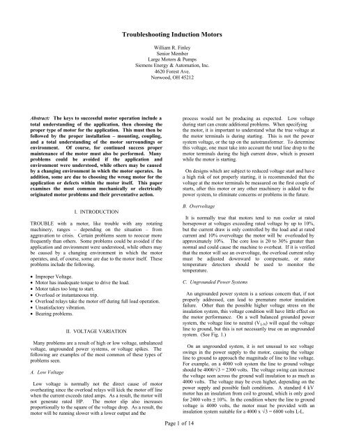
Troubleshooting Induction Motors - Siemens Industry, Inc.
Troubleshooting Induction Motors - Siemens Industry, Inc.
Troubleshooting Induction Motors - Siemens Industry, Inc.
You also want an ePaper? Increase the reach of your titles
YUMPU automatically turns print PDFs into web optimized ePapers that Google loves.
stated that there are special applications that do require highLRT, but these represent a very small percentage of the aboveNEMA business. Also, in most of the discussions in this paper,it is assumed that the locked rotor current is restricted to 650%of rated current. It is possible, in many motors, to increase theflux densities, thereby increasing the locked rotor torque and% Speed10090807060504030201000 50 100 150 200 250% TorqueFig. 4 – Typical Load and Motor Torque Curvescurrent without detrimental effects to the heating or otherperformance characteristics if the increase in locked rotorcurrent (LRA) is acceptable. As a point of interest, InternationalElectrotechnical Commission (IEC) standards permit higherLRA than NEMA or what normally is accepted in the UnitedStates.1009080706050403020100Fig. 5 – Motor with Higher Locked Rotor TorqueB. Reduced Voltage StartDifference = T A100% Voltage90% VoltageNEMA Load CurveSpeed of LeastAcceleratingTorque (T A)Speed Past WhichMotor Will NotAccelerate100% Voltage90% VoltageNEMA Load Curve% Torque0 50 100 150 200 250NEMA requires that a standard motor has adequate torque at90 and 100% rated voltage to start a fully loaded pump, fan, orcompressor, which has a 100% load curve as shown in Fig. 3.All United States motor manufacturers produce motors to therequirement as standard. As a result, there normally are veryfew problems in starting unless the load curve exceed thoseshown in Fig. 3, and this information is not properly relayed tothe motor manufacturer.The real concern exists when it is required to start equipmentwith a reduced voltage of 65 or 50%, due to an autotransformer,reactor starter, or solid state starter. Also, a Wye-Delta start issimilar in its effect on torque as would be seen on a 65% voltagestart.First of all, starting a fully loaded machine with 65 or 50%rated voltage or a Wye-Delta start should be strongly avoided.Although it may be possible to design a very special motor for% Speed10090807060504030201000 50 100 150 200 250% TorqueFig. 6 – 50 and 65% Reduced Voltage Startthis severe requirement, it would require a considerable increasein frame size, and a decrease in efficiency and/or a largeincrease in LRA to achieve the torque. (See Fig. 6.) This loadcurve, using a standard motor design starting at 50 or 65%voltage against a full load start, will clearly hang up and will notaccelerate past 40% speed at 50% voltage. Fig. 7 shows thesame motor at 50 and 65% voltage, but with a greatly reducedload curve. It may appear that this motor will start, but if thereis any additional voltage drop as would normally be seen inmost applications, this motor would hang up or take too long toaccelerate. (See Fig. 7.)The most common cause of a motor not starting at reducedvoltage is due to poor communication among user, motormanufacturer, and process equipment manufacturer (fan, pump,compressor, etc.). Experience has proven that the following arenot normally communicated very well:• actual voltage delivered to motor terminals• load torque• load wk2.C. Actual Voltage at Motor Terminal100% Voltage65% Voltage50% VoltageNEMA Load CurveActual motor terminal voltage is probably the most poorlycommunicated. Load torque and Wk 2 are at times very difficultto obtain, but at least when they are communicated, they arenormally correct and clear. This is not always true aboutvoltages. The greatest confusion is in the specification of 50 or65% reduced voltage start (RVS). It is normally specified thatthe motor be suitable for starting at 65 or 50% of rated voltage.This is almost always incorrect. The typical reason for RVS isdue to a weak power system requiring the current to be low onstartup to minimize line voltage drop. To minimize the voltagedrop is the key. Voltage drop will never be eliminated. As anexample, a 50% RVS on an autotransformer would supply 50%of rated voltage out of the secondary tap, minus whatever powersystem drop is seen between the transformer and the motorterminals. It is not unusual to see voltages at the motor terminalsat 42-45% of rated voltage with a 50% tap on anautotransformer. This can be very serious, and would mostlikely cause the equipment not to start.Page 3 of 14
100As can be seen here, it is very dangerous to assume any type ofload or load curve without specific information from theequipment manufacturer.90% Speed80706050403020100Fig. 7 – Reduced Load CurveNEMA makes recommendations for standard motors to whichall U.S. motor manufacturers design. NEMA recommends that astandard motor be capable of starting a 90% of rates voltage,which is assumed to be a typical line drop, but this is not alwaysrecognized for RVS. Due to this, it is always important that thetrue voltage at the motor terminals be given to the motormanufacturer in one form or another. To say the motor must besuitable for 50% reduced voltage start is very dangerous. Itshould be stated as suitable for 50% RVS or autotransformer tapplus a 10% voltage drop. This would result in 45% voltage atmotor terminals. (See Fig. 8.)D. Load Torque0 50 100 150 200 250% TorqueTorque and Load CurveAre Too Close25% Load100% Voltage65% Voltage50% VoltageMany times, the motor manufacturer is just told that the valvewill be closed (pump), dampers closed (fan), or that the vanesare closed (compressor). This supplies some information, but notenough to guarantee proper starting all of the time. Thefollowing table gives typical full speed torques on start-up, seenon various types of equipment.TABLE OF STARTING CONDITIONS(TORQUE AND CURVE SHAPES MAY VARY)Torque at FullStarting Condition Speed at StartPump (Centrifugal) Valve Closed 25 – 40%Fan Dampers Closed 40 – 90%Compressor(Centrifugal) Vanes Closed 25 – 60%The above table does not include screw compressors orvacuum pumps, which have very high torque requirements atvery low speeds. These require special considerations by motormanufacturers. (See Fig. 9.) Special applications such as thiswill require that a motor be designed around the load curve.These are a small percentage of the applications, but they willcause considerable problems if not properly designed.Since the torque requirements for fans/pumps and centrifugalcompressor vary considerably and compressor torque curveshapes vary so greatly, it is important that the load torque curvebe available.% SpeedE. Load Wk 2Fig. 8 – 45% VoltageThis requirement and concern is totally separate from the loadtorque requirement. The difference between the load andmotor torque determines the amount of torque available for% Speed100908070605040302010010090807060504030201000 20 40 60 80 100% TorqueFig. 9 – Screw Compressor Coreacceleration (T A ), and whether the equipment will accelerate atall or hang up at some subsynchronous speed. (See Fig. 4.) Theload Wk 2 determines how long it takes to accelerate and howmuch heat is generated in the rotor bars, and connectors, andstator winding. Heating and acceleration time is directly proportionalto Wk 2 .225%50%100% Voltage45% Voltage65%Speed Past WhichMotor Will NotAccelerateLoad Curve50% Voltage0 50 100 150 200 250NEMA LoadScrew Compressor100%High Torque Required at LowSpeed, Will Cause Trouble fora Standard Motor at ReducedVoltageWk xRPMt == acceleration time (1)308xTAHeating during acceleration is proportional to I 2 T.High Wk 2 requirements normally require that the active motormaterial be increased to act as a heat sink, reducing thePage 4 of 14
temperature rise during acceleration rather than increasing thetorque.It is relatively easy to get Wk 2 requirements from fan andcompressor manufacturers since they normally understand theconcern due to high inertias frequently seen. NEMA publishesrecommended standard levels for all motors. Fans andcompressors can, at times, exceed three-four times the Wk 2recommended by NEMA. Levels on centrifugal pumps arenormally very low.At times, it is very difficult to get this information from thepump manufacturer. Many times, this delays the motor designuntil the motor manufacturer feels comfortable with theapplication. The motor manufacturer must be sure that the pumpmanufacturer is not talking about a vacuum pump, which canhave a high Wk 2 and thus would create a serious problem. Inany case, the load torque curve and Wk 2 must be known and themotor designed to ensure successful motor starting.IV. DIFFICULTIES IN STARTINGThere may be times when the user believes that he has taken allstarting requirements into account, but the equipment still willnot start, or it takes too long and the overload relay takes themotor off line. In general, during starting, the overload relayswill take a motor off line in about 7-10 seconds at full voltage ifthe motor is not up to speed, or 25-35 seconds at 50% RVS.High inertia applications, such as fans and some compressors,will require that the overload relay be bypassed or delayedduring start-up. If this has been checked, or the accelerationshould not take that long, other areas will have to be reviewed.In many of the cases where the equipment would not accelerateto full speed, it was found that the motor did not actually hangup, but was just taking too long. In these cases, a test can beperformed to verify or check the load torque. Find out how longthe motor can be accelerated from a cold condition withoutdamage. For a one-start acceleration from cold, the motormanufacturer can normally permit a much longer accelerationtime. The motor manufacturer can also supply the line amps,which will be seen at various load conditions at full speed. Ifthe motor is allowed to accelerate for the longer period of timeby manually bypassing the overloads, the motor amps at fullspeed can be recorded and the loading established based on theload information provided by the motor manufacturer. If theload is greater than expected, it is normally possible to reducethe load during starting by adjusting the vanes or valve on thecompressor. Or, this can be done by locating air leaks arounddampers on fan applications, or by closing the valves further onpump applications. This is the best way the loading can bedetermined and corrected without returning the equipment to thefactory for special testing.During the above-mentioned acceleration, the voltage at themotor terminals should have been monitored. This informationcould point out an unsuspected drop of motor voltage. It isimportant to note that the voltage of concern is the voltage at themotor terminals during start-up, not after or before start, and notat the control panels. It is common to see an additional 2-5%voltage drop between controller and motor during start-up.If the voltage is low, the cause of the low voltage should belocated. Sometimes, the voltage tap on the transformer can bestepped up 2-5%. At times, it does not take much of a voltageincrease to eliminate the problem since torque varies as thesquare of the voltage. In addition, the motor manufacturer mayallow a longer acceleration time at this lower voltage since theheating in the motor is a function of the I 2 t and the current isproportional to the voltage.The majority of the problems with these applications have beensolved by the above steps. A small number of cases that cannotbe solved in this manner may require more drastic steps, such asa new rotor or even a new motor to produce greater torqueduring starting. Before anything is done, it is important to gothrough the above steps to verify the terminal voltage and loadtorque, and compare it to the design motor torque at the terminalvoltage to determine the true cause of the problem. Decide if themotor is not accelerating, or is just taking longer than expected.Keep in mind, as stated previously, that the overload will take amotor off line on long accelerations if they are not delayed. Thisis one of the biggest causes of nuisance trips during initial startups.V. MOTOR INSTANTANEOUSLY TAKEN OFF LINEThis is one of the most common problems seen in theapplication of motors today. In the past, the National ElectricCode (NEC) permitted a maximum instantaneous trip current at13 times the full load rated current. This is a very misleadingsetting. A typical motor with 650% locked rotor current (LRA)will have a peak instantaneous current of 6.5 times the squareroot of 2, equal to 9.19 times rated. This is not the current thatwill be seen the moment the breaker is closed. At start, when thepower is first applied to the motor, there will be a dc offset dueto at least two of the three phases being energized out of phasewith the field in the motor. At equilibrium when the motor isidle, all three phases are at zero potential. When the power isapplied to the motor, one of the power lines may be at its peaknegative or positive potential, as shown in Fig. 10 (a) or (d) forphase A. In the best possible condition, as shown in Fig. 10(b)or (c), the power is energized 30 o from its peak to 0.86 times itspeak potential for phases B and C. In the worst case conditionwhere the power is energized at its peak potential, the maximumpossible peak current is equal to the peak LRA of 9.19 plus thedc offset. This resulting peak current is equal to 2 times 9.19minus the exponential decay. The dc time constant andinstantaneous current can be calculated by the followingformula:⎛⎞⎜⎟⎜ Xs ⎟Ta = ⎜⎟(2)⎜⎛ LLs ⎞⎟2 * 3.14 * f * r1⎜1+ ⎟⎝⎝ kW1⎠ ⎠−ti instaneous = 9.19 (e Ta - cos wt) p.u. currentwheret = time in secondsw = 2pf radians/secondXs = total starting reactance per phase at zero speed andlocked rotor currentLLs = fundamental-frequency component of stray loadloss in kW at rated current.f = rated frequencykW 1 = stator I2r loss in kW at rated current and operatingcurrentr1 = stator dc resistance per phase corrected to operatingtemperature.Page 5 of 14
As can be seen in Fig. 10 (e), the peak instantaneous currentstarts at 18.38 times rated current, which is well above the NECsetting of 13 p.u. The NEC has recently changed this to 17 p.u.on energy-efficient motors. The first peak will actually occur 1/2cycle after the instant the motor was energized (0.5*1/60) =0.00833 s. As shown in the example in Fig. 10 (e), for a typicalmotor, the peak instantaneous current will still be above 16 p.u.Even if the phases were lined up in the best condition, 30 o offits peak, resulting in a peak approximately 0.866 times 16 p.u.equal to 13.8 p.u. with the 13 p.u. setting for non energyefficientmotors, the breaker will still trip most of the time. Onlyif the motor had lower than 650% LRA, or a very significantvoltage drop, would the instantaneous relay not take the motoroff line. An alternate would be to dampen the trip beyond thefirst 1/2 cycle. At the second 1/2 cycle peak, as shown in Fig. 10(e), the peak current will be near or below 13 p.u. With thismay be due to the normal tendency to design them closer to theupper LRA limit in an attempt to get higher efficiency, inaddition to reducing the losses by reducing stator resistance (r).As can be seen in the above formula for the dc time constant,reducing r will extend the open circuit time constant, resulting ina slower decay.This change to 17 p.u. on energy efficient motors is the resultof years of work of NEMA with the National Fire ProtectionAgency (NFPA) to change the National Electrical Code (NEC)to values of FLA and LRA that were more compatible withmotor designs. Now, it may not be quite as important since thedifficulty in starting has been addressed with the introduction ofinstantaneous trip damping. However, non energy-efficientmotors may still see some nuisance tripping with the 13 p.u.setting. If you are experiencing this problem in starting,consider going to a relay which has trip damping.CAYAB(a)BC(c)BCBY(b)A(d)ACXXVI. OVERLOADS SHUT DOWN MOTORIf the motor is drawing more than rated current at full load, themost likely cause is excessive load or undervoltage. The fullload amps on motors with efficiencies in the high 90's can bepredicted very accurately, and normally are within 2% of therequired amp draw for the load, whereas the load equipmentwhich may have efficiencies less than 50% can easily be off by5-10%. The voltage also plays an important part. If the voltagewere down by 10%, it would require 10% overcurrent to providerated torque. Also, the load will vary as the material beingprocessed changes temperature. Liquid and air handlingequipment requires more horsepower to process cold materialthan it does when the material reaches its designed operatingtemperature.Peak Instantaneous Locked RotorCurrent with Motor 650 % RMSSo, if you experience a problem with overcurrent, 1) check thevoltage at the motor terminals, 2) review the specifications onthe load equipment and verify the proper design temperature ofthe material being processed, and then 3) verify the amp ratingwith the motor vendor.Per Unit Current20151050-5-10-15NEC Relay Setting 13 P.U.NEC Relay Setting 17 P.U.Steady State Peak LRA2 22 42 62 82 102 122 142162 182Time in Milliseconds(e)Fig. 10 – Instantaneous Currentcondition, we have found that most motors will start with a l/2cycle damping with very few nuisance trips with the 13 p.u.setting. Even though some motor designs may still be slightlyabove the 13 p.u. at 0.025 s, the power system will usually havea small voltage drop, be energized slightly away from its peak,or the motor starting current may be lower than the 650% limitwhich will allow it to start. It has been reported that highefficiency motors tend to have more difficulty in starting. ThisPage 6 of 14VII. MOTOR OVERHEATINGThe most common cause of overheating is improper ventilationor high ambient temperature. A typical compressor room orpump house will heat up quickly if the room is not properlyventilated. A room that houses (4) 600 hp motors and pumps orcompressors may only be 40 x 60 x 30 ft high. Four motors thatsize will intake and exhaust 6000 CFM of air at approximately40 o C above inlet temperature. If the room is not ventilated, allthe air in the room will be exchanged within 12 min., potentiallyraising the ambient temperature 40 o C above, the originalambient temperature. The temperature in the room will continueto rise until it reaches an equilibrium with the heat radiating outthrough the walls. This may seem a little ridiculous, and onemay assume that everyone would know to avoid this condition,but rooms such as this have existed in various plants around theworld, and motors were failing repeatedly until fans wereinstalled in the walls to exchange the necessary amount of air.There are other conditions, which are not quite as obvious, butare still very detrimental to the motor performance. Themaximum ambient temperature permitted at the motor isnormally 40 o C. This is the maximum temperature allowed at theinlet to the motor. There may be pockets of hot air in a room dueto improper ventilation, obstructions, or being close to anotherheat source such as a compressor. A common problem is the
with a change of operating conditions. The rotating part, such asan exposed portion of the shaft, should be visibly marked with aseries of numbers around the circumference, or attach a targetfor a phasor to determine the high side of vibration duringoperation.Vibration readings should be made precisely at the operatingconditions already chosen and recorded. Because vibratorycharacteristics often change when operating conditions change,it is important to keep consistent conditions of operationthroughout a vibration analysis.The most productive next step is checking external items, suchas the following.and simple unbalance each produce a characteristic plot ofvibration amplitude with a reduction in speed when power is cutoff. (See Fig. 13.)If resonant frequency of the support coincides with theoperating speed of the machine, or with half or twice rotationalspeed, it will be nearly impossible to maintain a smooth runningmachine. Just a slight imbalance will cause noticeable,sometimes violent vibration at the resonant frequency. Unlessthe machine can be precision-balanced and so maintainedthroughout its life, changing of the support resonant frequencyusually is recommended.1. Are all foundation bolts tight? Are the shims betweenthe motor feet and mounting surface tight? Try tomove them with pliers or hammer, or insert a feelergauge between the motor feet and support. If anylooseness or space is found, the motor needs to berealigned, properly shimmed, and hold-down boltstightened so that the motor is equally and solidlysupported by all supporting surfaces.2. Check visible fasteners on the motor for tightness',such as bearing housing bolts. Tighten any foundloose. When the load produces impacts, such as by ahammermill bolts may work loose if they are notlocked.3. Check the horizontal vibration of the motor feet or, forvertical motors, the base ring. If the vibration exceeds30% of the horizontal vibration of the motor bearingsat the shaft centerline, the motor mountingarrangement may be weak or resonant. An analysismay be made by measuring and plotting horizontalvibration at intervals, such as each 6 in, from groundor floor level to the top of the motor. Results of suchan analysis are illustrated in Fig. 12, which shows themounting structure to have problems-perhaps a gapbetween base and ground, or a resonant or weak base.This analysis is equally effective on vertical machines.One way to determine whether vibration is caused byresonance, rather than electrical disturbance or simpleunbalance, is to observe the vibration closely at the instant themachine is deenergized. If the vibration disappears instantlywhen power is cut, the trouble may be electrical in origin. If thefoundation structure is resonant at or near operating speed, thevibration also disappears rapidly when power is cut off, but notinstantly as for electrical vibration. Because a motor deceleratesrapidly when power is cut off, vibration due to simple unbalancealso diminishes. Thus, only very careful observations ensure thata reduction of vibration is not due strictly to the reduction inspeed.When a resonant condition is suspected as the cause ofvibration, it is recommended that vibration amplitude and phaseangle versus speed be plotted. Resonance, electrical disturbanceVibration AmplitudeFig. 12 – Example of Weak BaseVibration at Rated Voltage and 100% Full Load and SpeedMechanical UnbalanceResonant Structure60 65 70 75 80 85 90 95 100% Full Load SpeedElectrical UnbalanceVibration AfterRemoving VoltageFig. 13 – Characteristic conditions of vibration amplitude versusspeed following removal of voltageSupport resonance (Fig. 14) peaks at natural frequency. Thecurve is for a 3600 rpm machine, support resonance 1810 cpm.If the motor and driven loads are mounted on a common base,see if the base is in more than one piece, with a bolted jointbetween the motor portion and driven load portion of the baseassembly. If so, examine carefully at the joint to see if bolts aretight and if the base under the motor has shifted relative to thebase under the load. If so, the shaft alignment has also shifted.Page 8 of 14
VIBRATION, MILS4321Fig. 14Sometimes the "sympathetic" vibration of a part attached to themotor will cause increased vibration amplitudes at the motorbearing housings. Parts attached to the motor include lube oilpiping, air housings, etc. Considering that the resonantfrequency of any part is related to its gravitational sag by theformula resonance frequency in cycles per minutes it is apparentResonantFrequency = 187.700 1000 2000 3000 4000for instance, that if a pipe sags 0.0027 in between supports, itsnatural frequency will be 3600 cycles/min. If attached to a 3600rpm motor, it would be excited at its natural apparent forinstance, that if a pipe sags 0.0027 in between supports, itsnatural frequency will be 3600 cycles/min. If attached to a 3600rpm motor, it would be excited at its natural frequency andwould probably vibrate excessively. The solution is easy; justadd a pipe clamp in between the others. If the parts vibrating areportions of the air housing, mounting the air housing on a gasketinstead of directly on the metal portions of the motor will oftenreduce vibration, as the gasket will reduce the vibration energytransmitted to the air housing.THE RELATIONSHIP OF GRAVITATIONAL SAG ORDEFLECTION AND RESONANT FREOUENCYGravitationalDeflection(inches)0.0980.0240.0110.00270.00120.00068SPEED, RPMResonantFrequency(cycles/minute)60012001800360054007200Shaft alignment should be checked. Bases and foundationssometimes shift, and machines sometimes shift on their bases.An extreme case which comes to mind was an installation of a3000 HP motor driving a car-shredding hammermill. Thehammermill would chop complete automobiles into clean, fistsizedchunks, at the rate of 30 autos/hour. The first hour of eachworking day was utilized in tightening the hammermillfastenings and realigning the shafts, which moved as much as1/8 in a day's operation.1∨ gravitational sagin inches(5)Page 9 of 14Misalignment manifests itself in various ways, often in a twicerotationalfrequency vibration of particularly large magnitude inthe axial direction. It should be noted that it is the shafts whenturning in their respective bearings that must be aligned, not thecoupling surfaces. In the absence of a company ormanufacturer's tolerance for alignment of motor shaft to drivenequipment shaft, 0.002 in is a useful tolerance.When in doubt as to whether the vibration originates in themotor or the driven machine, the coupling halves may beloosened, one half and its associated machine shaft rotated 180 o ,and the halves recoupled. If under the same running conditionsas before the vibration high side is the same, then the source ofvibration is in the machine on which the phasor target or anglenumbers are marked. Conversely, if the high side shifts 180 0 , thecause is in the other machine.When the source of vibration is found to originate in the motor,a solution can be achieved. If the frequency of vibration isexactly at rotational speed and amplitude of vibration and phaseangle or high side remains constant, the problem is probably oneof simple unbalance. This can be corrected by standardbalancing procedures. A simple unbalance may be caused bynonsymmetrical rotating parts, a slightly bowed shaft, or anonconcentric or improperly assembled coupling.Add balance weights to an external element, such as a couplingor belt pulley first. This usually is the most accessible spot toadd balancing weight. Also, the effect of a given weight isgreater then added here than between bearing centers, as a givenunbalance has a greater effect here. When an insufficient orincorrect balancing effect is obtained, the machine must beopened and weights added to the rotor body.If vibration frequency is at rotational speed, but amplitudeand/or phase angle initially wander and either stabilize orcontinue to wander with time, the problem may be one of therotor rubbing a stationary part, such as a shaft seal. If wanderingof amplitude and/or phase angle stabilizes or tends towardstabilization, the seal probably was installed incorrectly and“wore itself in.” When vibrational wandering does not stabilize,the seal or other rubbing part should be investigated andcorrected. Typical clearance of seals is shown in Fig. 15.A frequency of vibration of twice rotational speed may indicatea poorly shaped sleeve-bearing journal, misalignment, orlooseness and movement between parts. "Poorly shaped journal"means a shaft sufficiently bent to show nonconcentricity in thejournal or an out-of-round journal surface. Severity of thisnonround surface varies from several ten-thousandths of an inchfor 3600 rpm machines to 0.001 in for slow speed machines.Looseness or movement of rotor parts, indicated by a vibrationat twice rotational speed, may be thought of, for example, as afan with an oblong bore which rocks about its tight diameteronce per revolution. Because of large centrifugal forces onlarger diameter machines at higher speeds, rotor parts whichmay be extremely tight when installed, may become loose whennot properly designed, or altered during repairs.A frequency of vibration at about half rotational speed suggestsbearing oil film disturbances, in which the journal is not stable atone location in the bearing during operation; instead, if whirlsabout a center in the bearing. This condition usually appears inhigh-speed machines and indicates either that the oil is too
heavy or bearing clearance insufficient (assuming properbearing design and previous successful operation). The operatorshould check to make certain the proper oil is used in thebearings. When the grade and type are found to be correct, theclearance of the bearing should be checked. This may be doneby micrometer, feeler gauges, measuring the thick-ness of softlead pressed between shaft and bearing or by plastigauge.DIAMETRIAL SEAL CLEARANCE - INCHES0.0270.0240.0210.0180.0150.0120.0090.0062 3 4 5 6 7 8 9 10DIAMETRIAL BEARING CLEARANCE - INCHES0.030.0240.0160.008MAXIMUMMINIMUMSHAFT DIAMETER - INCHESFig. 15 – Diametrical Seal ClearanceMAXIMUMMINIMUM00 4 8 12HORIZONTAL SLEEVE BEARING BORE - INCHESFig. 16 – Diametrical Bearing ClearanceVibration dampening is obtained from the bearing oil film, sobearing clearance should not be so great as to lose this benefit.However, bearing clearance should not be unduly reducedbecause too small a clearance promotes oil whirl and hot bearingoperation. The operator should strive to maintain bearingclearances as specified by the manufacturer. Fig. 16 showsnormal bearing clearances for horizontal bearings. Oil film whirlor subharmonic vibration, at approximately half rotationalspeed, can also occur in bearings utilizing a circulating oilsystem, if the oil entering the bearing is too cold, as this has thesame effect as using too heavy an oil. Normal inlet oil temperatureshould be 35-45 o C.If vibration frequency is exactly at rotational speed butamplitude and/or phase angle change rapidly after start-up andtend to stabilize within 30 mm or so, the problem probably isone of thermal unbalance; that is, heat in the rotor affects shaftstraightness or rotor parts location. Solutions to this problem areas varied as the types of rotors, but usually require work on therotor to eliminate the changing unbalance.Electrical causes of vibration generally exhibit one of twoconditions. The simplest to find is a fixed 120 Hz vibration,which is a transformer-type vibration of the stator due to theimpressed 60 Hz voltage. In certain types of machines, thisvibration is transmitted readily through the machine structure tothe bearings. Usually, the entire machine will vibrate at thisfrequency, but will stop with removal of voltage. Often,strengthening the motor supports or securing the machine morerigidly to its foundation will reduce this vibration to anacceptable level.The other common form of electrically induced vibration is a"slip-beat vibration" at rotational frequency, with the amplitudevarying periodically at exactly the slip speed times number ofpoles. For example, an induction motor operating at 1783 rpm(four-pole, 1800 rpm synchronous speed) will have a slip-beatvibration of 68 cpm. This vibration is due to the flux level in thelaminated cores of the motor and minor dissymmetry in themagnetic circuits. In most cases, it is not discernible or barelydiscernible. This noise is often heard in motor rooms where twoor more machines are operating at essentially the same speed, inthe same way that a "beat" is heard in multiengine airplanes orboats with unsynchronized engines.When a slip beat frequency noise or vibration suddenly appearsin a motor, the machine should be checked, particularly whenthe associated vibration amplitude fluctuation is large. Possiblecauses are broken rotor rods or end connector, bent shaft, orunbalanced stator voltage. The cause can be found by operatingthe motor at no load. If the trouble is in the rotor cage, thevibration fluctuations diminish at no load because it is a functionof current. However, if it is a bent shaft, the vibrationfluctuations remain (at a lower frequency due to less slip at noload) because they are related to machine voltage. See Fig. 17.Vibration wave shapes (Fig. 17) help to isolate cause ofvibration. Such waves are of three types.A rough anti-friction bearing gives a relatively high frequencyvibration, several times the frequency of rotor speed, but notnecessarily a direct multiple. This problem is indicated by anunsteady frequency and, sometimes, amplitude as well. Thevibration continues when an operating machine is deenergizedand coasts to a stop. The solution is to repair or replace thebearing.Vertical machines with sleeve guide bearings may have aunique vibration problem. Sleeve bearings on vertical machinesdo not have the same type of load carrying hydrodynamic oilfilm as horizontal sleeve bearings since horizontal sleevebearings support the weight of the rotor. To prevent shaft whirlor shaft floating in the bearings, causing random frequency ofvibration, the diametrical clearance of vertical sleeve bearings isless than for horizontal bearings of the same diameter. Fig. 18gives typical diametrical clearances of vertical sleeve bearings.Torsional vibration is seldom a problem with induction motors,but may be a problem with synchronous motors during startingif not provided for in design of the motor and shaft system.Likewise, a load which routinely gives torsional impacts, like apulverizer or hammermill, or an accidental shock, like a loggoing into an operating pump, may be a problem if not foreseenand provisions made for the special application.Page 10 of 14
DIAMETRIAL BEARING CLEARANCE0.0120.0080.004Fig. 7 – Vibration Wave ShapesMAXIMUMMINIMUM02 6 10 14VERTICAL SLEEVE BEARING BORE - INCHESFig. 18 – Diametrical Bearing ClearanceIn almost all cases, the result is a twisted drive shaft extension,and/or an offset coupling key, and/or a damaged coupling. Seereference paper [5] for a diagnostic chart and more informationon solving vibration problems.IX. ANTI-FRICTION BEARINGSProblems with anti-friction bearings are most often analyzed asdue to poor lubrication. This is often only the first analysis, aslubrication tries to overcome other, more subtle, problems.Manufacturers design the bearing arrangement of motors forlong life, but often, the bearings do not attain their calculatedlife expectancy.Design criteria used for bearing life are based on fatigue of thebearing metal and are usually in terms of L10 life which is thenumber of hours when, on a statistical basis, 10% of thebearings fail. The average designed bearing life then is fivetimes the L10 life. Commonly used criteria range from an L10life of one year (average life of five years) for vertical motorsand belt drive machines to an L10 life exceeding 100000 h (11.4years, average life of 57 years) for larger horizontal directconnected motors. The calculated life expectancy of anybearing is based on four assumptions.Page 11 of 141) Good lubrication in proper quantity will always beavailable to that bearing.2) The bearing will be mounted without damage.3) Dimensions of parts related to the bearing will be correct.4) There are no defects inherent in the bearing.In addition to poor lubrication, other causes contributing tobearing problems may include1) Defective bearing seats on shafts and in housings2) Misalignment3) Faulty mounting practice4) <strong>Inc</strong>orrect shaft and housing fits5) Ineffective sealing6) Vibration while the bearing is not rotating7) Passage of electric current through the bearingSpecific problems and solutions for anti-friction bearings willnot be detailed here since there are very good papers andpublications available for assistance. In the absence of asatisfactory source of information on this subject, [4] containsuseful in formation. It is important to properly maintain antifrictionbearings to attain long, trouble-free motor life.X. SHAFT VOLTAGEVoltage is generated in the rotor of each induction motor by themagnetic flux passing through nonsymmetrical portions of itspath. The nonsymmetries may be very small, and so in smallmachines have very little effect in generating voltage in therotor. The effect is more pronounced in larger machines, as itmay vary from just a few millivolts in a small machine to over avolt in a large machine when measuring between ends of themotor shaft. In addition, induction motors powered by variablefrequency power sources may have appreciably higher shaftvoltages, due to the power source transient voltage spikes, thanthe same motor will have when its power source is a steady sinewave. Also, caution is necessary in installations with variablefrequency power sources as the transient voltage spikes mayreflect into the power supply and cause higher shaft voltages onother, nonvariable speed machines on the power system.The shaft voltage will follow a complete circuit, if available,through the motor's bearings and the frame or foundation,allowing current to flow across the bearings. Normally, voltagelevels below 0.5 V will not cause harmful currents. Whenexpected or measured shaft voltage is above 0.5 V, provisionsare made to open or break the circuit to prevent current flow.The normal method is to insulate the motor bearing at the endopposite to the coupling end where the motor is coupled to thedriven equipment. And, of course, other connections to the motorshaft at the end opposite the drive coupling must also beinsulated to maintain the open circuit. Special provisions arenecessary in special cases to maintain an open circuit, such asinsulated drive couplings in large tandem motor arrangements,or when driving in auxiliary oil pump or other device on theoutboard end of the motor.On AFDs, there is still a concern that some medium voltagedrives may induce a high frequency common mode voltage andcurrent that may even pass through a conventional insulatedbearing since at high frequency the bearing and insulation willact like a capacitor with very low impedance to high frequencyvoltage. As a result, it may be necessary to add a shaftgrounding brush.
from the bearing oil sump, and on larger machines or in highambient temperature areas by auxiliary oil supplied to thebearing by an external source, and drained from the oil sumpback to the external source. The external source may be a motorpump-coolerunit, or often is pressurized supply, and drain lines,from the driven equipment.Fig. 19 – Sleeve BearingCurrent through a bearing can also be caused by such things aswelding on some part of the machine with the ground attachedso that the circuit is required to pass through the bearing, orfrom static electricity from such manufacturing processesinvolving leather, paper, cloth, or rubber. Harmful results occurwhen sufficient current passes from the shaft to the bearing andthen to a ground which is continuous to the other bearing. Whenthe current is broken at the contact surfaces between anti-frictionbearing rolling elements and raceways, arcing results. Thisproduces very localized high temperature and consequentdamage, which is described as fluting and looks like transverseflutes in the bearing raceways. Current in a sleeve bearingresults in pits in the surface of the babbitt, and in extreme cases,pits in the shaft journal surface and pulled babbitt.XI. SLEEVE BEARINGSSleeve bearing problems are generally of three types:1) Hot bearings2) Wiped or failed bearings3) Oil leaks.Sleeve bearings (see Fig. 19), by their very nature, are heatproducingdevices. The rotating shaft journal is separated formthe stationary bearing bushing only by an oil film. Consideringthat the oil adjacent to the shaft journal is moving at shaftjournal speed, while the oil adjacent to the stationary bearingbushing is stationary, it is apparent that the oil between the twosurfaces is being sheared at a very high rate. Shearing of oilrequires force, which in a time period equates to power which,being entirely absorbed in the bearing, equates to heat. A threeinchbearing journal, in a 3600 rpm motor, has a surface speedof 2826 ft/mm. The minimum oil film thickness between therotating journal and stationary bearing will vary fromapproximately 0.0025 in a cool bearing to 0.0008 in a warmbearing, which is operating near 185 o F. The shearing action ofthe oil thus takes considerable energy. Fig. 20 shows thepressure distribution between the bearing bushing and rotatingjournal. Note that the actual journal position is not centered inthe bearing bushing. This is due to the force required to shearthe oil "wedge" which is the oil being fed to the bearing.The heat generated at the bearing surface is removed through oilbeing supplied to and flowing through this area, by conductionalong the shaft, and by conduction from the bearing bushing toits housing, through the bushing support surfaces. Oil issupplied to the bearing surface by oil rings, which deliver oilFig. 20 – Diagram of full bearing showing oil film pressure<strong>Motors</strong> are usually designed so that cooling air coming intothe motor travels over the bearing housings, cooling them, onthe way into the electrical parts of the motor. In this way, manymotors have self-cooled bearings. In normal conditions, 3600rpm motors may have self-cooled bearings up through 3 in.diameter, and 1800 rpm motor bearings may be self-cooledthrough 4.5 in. diameter. Fig. 21 shows a typical path of coolingair entering a motor. Motor designers extend considerable effortto reduce the heat generated in bearings while maximizing thecooling and the operating oil film stiffness.High bearing temperature can then have one or more causes.There are several steps which can be taken in an analysis beforedisassembling an otherwise well-running machine.The oil rings should be turning a smooth manner, with oilflowing off them in a smooth manner. The rings should notbe oscillating rapidly in any direction. Normal rotational speedfor oil rings is from one-tenth of the shaft rotational speed at lowspeed, to 1/20-1/30 th of shaft speed for 3600 rpm motors.Fig. 21 – Cooling Air PathPage 12 of 14
Oil should be at its proper level. Foam may appear in the oillevel sight glass in the bearing housing for up to 1 h after startup.During steady operation, there should be only slight foamvisible. If the oil looks dirty in the sight glass, there is probablybabbitt or other foreign elements in the oil. This requires adisassembly. Feel the outer oil seal to see if it is approximatelythe same temperature as the bearing housing next to it. If it issignificantly hotter, it is probably rubbing the shaft and heatingthe bearing area. If the motor has a circulating oil supply,confirm that there is oil flow, in the quantity desired, and thatthe oil supply temperature is reasonable, approximately 35-45 o C. Check the air flow into and out of the machine to find if itis normal or restricted, and if the air entering the machine is at areasonable temperature, usually below 40 o C. Check the locationof the motor shaft in an axial direction if possible versus thecenter or extremes of its axial float. Positions of axial shaft floatare marked on many motors. Bearing temperature will be higherif a shaft shoulder is running against the bearing bushing.If all checks so far are okay, including clean oil in the sightglass, the bearing temperature measuring device may be checkedto be sure a true temperature is being transmitted to the controlor monitor. To check the temperature device, open the auxiliaryterminal box on the motor, disconnect the bearing temperaturedevice, and substitute test piece. For a thermocouple, this couldbe another thermocouple; then hold the measuring end to see ifthe monitoring instrument indicates the temperature of the handholding the thermocouple. If the device is an RTD, substitute aresistor for the RTD to check the mounting device. Useful valueof resistors to check RTD monitor operations are as follows:Type of RTD10 O at 25 o C10 O at 25 o C100 O at 0 o C100 O at 0 o C120 O at 0 o C120 O at 0 o CResistance(ohms)11.513.0120.0140.0160.0200.0TemperatureIndicated64 o C103 o C50.5 o C101.5 o C53.0 o C99.5 o CIf the problem has not yet been resolved, the motor needs to bedisassembled to examine the bearing bushing and shaft journal.As soon as disassembly has progressed far enough, check theclearance between the inner oil seal and the shaft to find if theinner oil seal has been rubbing the shaft. When the top half ofthe bearing bushing has been removed, check the bearingbushing alignment with the shaft journal. This can be done byinserting a fine feeler gauge - 0.0015 or 0.002 in. between theshaft journal and bearing bushing in each of the four corners.The feeler gauge should go into the space an equal amount,within, in all four corners.Examination of the lower half of the bearing bushing shouldshow that the shaft journal was riding equally along the lengthof the bushing. It could show the shaft riding on one end or onhigh spots, or perhaps the axis of the shaft journal and bearingbushing were not the same, so that wear spots occur on oppositecorners of the bushings. Perhaps the bushing has "pulled"babbitt, babbitt which has softened or flowed, or pitted babbitt,due to electrical currents through the bearings, or the babbittsurface may be destroyed, and the shaft riding on the seals.Page 13 of 14For proper operation, a bearing bushing should show contactwith the shaft journal axially in a narrow path along the bottomof the bushing from one end to the other. Abrasive screen can beused to lightly remove high spots in the babbitt to attain a goodcontact pattern. Bearings are carefully designed, for their,application, to exacting dimensions. Usually, removal of lessthan 0.0015 in thickness of babbitt will result in a satisfactorycontact pattern if dressing is needed. Some bearing bushingssupported near the ends may require more babbitt to be removedfrom one end to attain a good pattern. See Fig. 16 for typicalclearance between the shaft diameter and bearing bushing bore.Oil ring speed is important to provide sufficient oil to thebearing surface. Oil rings are driven only by friction of the oilfilm between the ring and shaft, so any burrs or roughness on thering or in the ring slot of the bushing must be removed. Thebearing arrangement can then be reassembled with the above inmind. Since the shaft will rise and be supported by the oil filmduring operation, normal practice is to adjust noncontactingshaft seals with one-third of the clearance on the bottom andtwo-thirds on the top, one-half on each side. Fig. 15 illustratesnormal shaft seal diametrical clearance. After assembly, freerotation of the rotor by hand will ensure no rubs, and freerotation of oil rings while turning the rotor will ensure theirproper oil delivery.Oil leak problems in sleeve bearing arrangements aresometimes very subtle and difficult to resolve. Among the easierto solve problems are leaks in piping, leaks at entrance to thecapsule, such as an oil level glass, and metal-to-metal joints notproperly prepared with sealant such as RTV or Permatex. Jointsthat may leak include, for instance, between the upper and lowerhalf of the split bearing capsule and the capsule faces where theseals are attached. Sometimes, the tapped holes for capscrewssecuring the shaft seals go through the wall into the oil cavity,below the oil level, so care is required during assembly.The oil level, including any foam on top of the oil, must bewell below the lowest point of the shaft where it comes throughthe shaft seal. If an oil which is prone to foaming, such asrefrigeration oil, is used, oil may seep out through the shaftseals. When using other types of oil, contact motormanufacturer. High grade mineral turbine oils are less prone tofoam and are recommended for motors.In labyrinth-type sealing arrangements, a drain at the bottom ofthe inner half of the labyrinths of the first labyrinth seal on eachside of the bearing bushing will drain the condensed oil vapor,which has been 'caught" by the seal, back into the oil sump,rather than allow the condensed oil to build up and seep out ofthe bearing along the shaft.Varied arrangements are used to minimize the frothing of oil inthe bearing cavity, such as seal rings on the bearing bushing,covers over oil slingers, etc., with the goal of keeping to aminimum the amount of oil vapor generated in the bearingcavity. Part of preventing leakage of oil vapor either to theoutside or into the motor is to keep the generation of vaporavailable low; the other part is to keep the pressure in thebearing cavity low. An internal pressure or vacuum below 0.2 inof water column in the bearing cavity will normally preventleakage of oil vapor.<strong>Motors</strong> are cooled by air flow which is normally drawn into themotor over the bearing housings. See Figs. 21 and 22. This air
cools the bearings before entering the motor rotor and stator.The velocity of cooling air past the bearing housing can be ashigh as 3000 ft/mm, depending on the size and speed of themotor. This air flow creates a vacuum in the vicinity of the innershaft seals, and if these seals are not effective or properlyassembled, will draw a vacuum in the bearing cavity, and thusdraw oil vapor into the motor. There are various shaft sealingmethods, among which is the arrangement of Fig. 21. Thislabyrinth arrangement, used on medium sized motors, consistsof two individual labyrinths. The space between the labyrinths isvented to outside the motor, and allows vacuum inside the motorto draw air from the vent through the inner labyrinth, whichreduces or eliminates the vacuum at the labyrinth adjacent to thebearing, so that the pressure/vacuum in the bearing cavityremains at a safe, low level.successful troubleshooting is to identify and analyze all thepossible causes, and then eliminate each one either by testing orcalculations until the problem is properly identified. Thismethod helps the troubleshooter avoid jumping to conclusionsand making modifications to components that are not at fault.Just because a component does not perform properly does notnecessarily mean that it is at fault. Other environmental factorsmay be causing the failure, and the failures will continue untilthe environmental factor is corrected.REFERENCES[1] R. R. Burke, "Maintenance program spots, correctsmachine vibration," Elec. World, Jun 27, 1966.[2] R. W. Smeaton, Ed., Motor Application andMaintenance Handbook, R.R. Burke, contributingauthor. New York: McGraw-Hill, 1969/1987.[3] W. R. Finley, "Noise in induction motors-Causes andtreatments," IEEE Trans. md. AppL, vol.27, no.6, 1991.[4] Bearing Installation and Maintenance Guide, SKF USA, <strong>Inc</strong>.,February 1992[5] W.R. Finley, M.M. Hodowanec, W.G. Holter, “AnAnalytical Approach to Solving Motor Vibration Problems,”IEEE PCIC Conf. , Sept. 1999Fig. 22 – Bearing Sealing ArrangementFig. 22 illustrates the bearing sealing arrangement on a largehigh speed machine. This labyrinth has an additional feature inthat pressured air flows into the first chamber, between the firstand second labyrinth. Most or all of this air is drawn into themotor, through the motor-side labyrinth. The second chamber isvented to atmosphere, to neutralize the pressure, so that air is notforced into or oil vapors drawn through the labyrinth sealsadjacent to the bearings. Sizing of shaft seals and other bearingfeatures is carefully calculated and designed, so that carefulreassembly as originally assembled, with the aboveconsiderations in mind, will usually eliminate oil leakageproblems and lead to successful bearing operation.X. CONCLUSIONSuccessful motor operation depends on many things, but mostimportantly, the application and environment must be knownand its effect on motor performance understood. This paperattempted to highlight the most common causes of motortroubles, which account for the majority of problems. The key toPage 14 of 14


