

The Mollison International Switching Centre - ericssonhistory.com
The Mollison International Switching Centre - ericssonhistory.com
The Mollison International Switching Centre - ericssonhistory.com
- No tags were found...

Create successful ePaper yourself
Turn your PDF publications into a flip-book with our unique Google optimized e-Paper software.
ERICSSONREVIEW2THE MOLLISON INTERNATIONAL SWITCHING CENTRELONG DISTANCE TRAFFIC IN MEXICOINSTALLATION OF 12 MHz SYSTEMMULTIPLEX AND RADIO-RELAY EQUIPMENT1975 WORLDWIDE NEWS
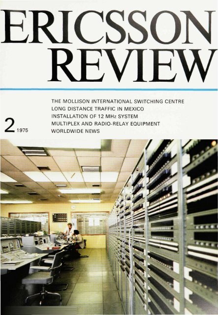
ERICSSON REVIEWNUMBER 2 • 1975 • VOLUME 52Copyright Telefonaktiebolaget LM EricssonPrinted in Sweden, Stockholm 1975RESPONSIBLE PUBLISHER DR. TECHN. CHRISTIAN JACOB/tUSEDITOR GUSTAF 0. DOUGLASEDITORIAL STAFF FOLKE BERGBO SEIJMER (WORLDWIDE NEWS)EDITOR'S OFFICE S-12625 STOCKHOLMSUBSCRIPTION ONE YEAR $6.00, ONE COPY $1.70Contents46 • <strong>The</strong> <strong>Mollison</strong> <strong>International</strong> <strong>Switching</strong> <strong>Centre</strong>61 • Long Distance Traffic in Mexico72 • <strong>The</strong> First Installation of LM Ericsson's New 12 MHz System76 • Multiplex and Radio-Relay Equipment for a 120-Channel PCM System90-WORLDWIDE NEWSCOVERTest consoles for measurements of thenational and international circuits in the<strong>Mollison</strong> <strong>Switching</strong> <strong>Centre</strong>, London
<strong>The</strong> <strong>Mollison</strong> <strong>International</strong><strong>Switching</strong> <strong>Centre</strong>Rowland W. Button and Manfred BuchmayerIn April 1972 the United Kingdom Post Office awarded LM Ericsson the Contractfor a large <strong>International</strong> <strong>Switching</strong> <strong>Centre</strong> (ISC) in London.<strong>The</strong> <strong>Mollison</strong> <strong>International</strong> <strong>Switching</strong> <strong>Centre</strong> is one part of the Stag Lane<strong>International</strong> Telephone Service <strong>Centre</strong> multitask project to establish one ofthe largest switching centres for international telephone traffic in the world.What made the <strong>Mollison</strong> project a special one to LM Ericsson was that with its25,000 ARM 20 crossbar positions, a switching capacity of 8,000 Erlangsand a call handling capacity of well over 100,000 calls an hour, it is the largestsingle international exchange project LM Ericsson had ever undertaken.Because the ARM 20 system with well over 600,000 lines in service by the endof 1973 is so well known, the system design will not be gone into in any greatdetail in this article. Instead, attention will be paid to the managementof the project, the special facilities offered and to the integration of <strong>Mollison</strong> ISCinto the UK national and international networks.UDC 621.395 722LME 83483035<strong>The</strong> <strong>Mollison</strong> orderIn September 1971, LM Ericsson, togetherwith other manufacturers of tele<strong>com</strong>municationequipment, was invitedby the United Kingdom Post Officeto submit a tender for the design,manufacture and installation of an international4-wire switching centre inLondon. Two switching units had to beprovided, one for outgoing internationaltraffic and one for in<strong>com</strong>ing internationaltraffic. <strong>The</strong> initial and finalcapacities of each of the units werespecified to be 1,500 and 4,000 Erlangsrespectively. Each of the units were tobe equipped with an internationalmaintenance centre. <strong>The</strong> Post Officeplanning strategy required the units tocater primarily for international subscriber-dialledtraffic originating andterminating in the United Kingdom. OnApril 27, 1972, the contract, which lateron came to be known as the <strong>Mollison</strong>Contract, was awarded to LM Ericsson.<strong>The</strong> contract is divided into threephases. <strong>The</strong> contractual handover datefor Phase I with a traffic capacity of3,000 Erlangs was December 27, 1974.Phase II with a traffic capacity of 2,000Erlangs and Phase III with one of 3,000Erlangs should be ready for service onDecember 27, 1975 and December 27,1976 respectively.As mentioned above, the order <strong>com</strong>prisedmanufacture, design, deliveryand installation of a 4-wire ARM 20 internationalswitching centre with aninitial capacity of 3,000 Erlangs and acontracted final capacity of 8,000 Erlangs.Within this framework twoswitching units had to be provided, onefor outgoing international traffic andone for in<strong>com</strong>ing international traffic.Each unit had to be served by an internationalmaintenance centre <strong>com</strong>prisingan <strong>International</strong> TransmissionMaintenance <strong>Centre</strong> (ITMC) and an <strong>International</strong><strong>Switching</strong> Maintenance<strong>Centre</strong> (ISMC). <strong>The</strong> equipment to besupplied had to be <strong>com</strong>plete, i.e. to besupplied as a working entity includingpower plant and rack lighting.Automatic transmission measuringequipment, service observation equipment,international accounting equipmentusing <strong>com</strong>puter techniques andmaintenance equipment were includedin the order.Three national line signalling systems,AC11, DC3 and LD4, were specified.<strong>The</strong> two first line signalling systemsmentioned are associated with theMulti-Frequency inter-register signallingsystem MF2.<strong>The</strong> third is a <strong>com</strong>bined line and registersignalling system with loop disconnectpulsing. <strong>The</strong>se signalling systemsare described in more detail underRegister signalling and signalling systems.Three international signalling systemswere also specified, CCITT 4, CCITT 5and CCITT R2.A training package for PO engineeringand maintenance staff, and provision ofa <strong>com</strong>plete training exchange were includedin the order.<strong>The</strong> international and nationalnetwork configuration of<strong>Mollison</strong> ISC '<strong>Mollison</strong> ISC position and importancein the international networkBefore phase I of the <strong>Mollison</strong> ISC wasbrought into service in October 1974,the Faraday and Wood Street ISCs hadto carry all international traffic to andfrom the United Kingdom.<strong>The</strong> total design capacity of these twoCT1 "full facility" ISCs was then about
47ROWLAND W BUTTONHead of Network Control Division,External Tele<strong>com</strong>munications ExecutivePos! Office Tele<strong>com</strong>municationsHeadquartersMANFRED BUCHMAYERTelephone Exchange Division,Telefonaktiebolaget LM Ericssonapplied to any ISC offering all internationallyagreed facilities.By the end of 1974, <strong>International</strong> SubscriberDialling (ISD) facilities wereplanned to be available for subscribersin 45 centres in the United Kingdom.At the same time approximately 65%of all international calls originating inthe United Kingdom were directly dialledby the subscribers. By the end of1979 ISD facilities will be availablefrom most United Kingdom groupswitching centres (primary centres)generating international traffic of morethan 0.25 Erlangs.With the rapid increase of ISD, thetraffic not requiring operator assistanceis taking a bigger and biggershare of the total international telephonetraffic. As a consequence thereis a trend towards diverting the ISDtraffic to big switching units handlingautomatic international traffic only.<strong>The</strong> <strong>Mollison</strong> ISC is such a unit andtherefore operator assistance and transitfacilities are not provided. It istermed a "limited facility" unit. Operatorsof distant administrations may dialthrough the unit provided no UnitedKingdom operator intervention is required.<strong>The</strong> introduction of the <strong>Mollison</strong> ISCwill affect the network functions of theWood Street and Faraday ISCs. Muchof the growth of ISD traffic will bediverted to the <strong>Mollison</strong> ISC and onlytraffic for which full facilities are essentialwill be connected to the UK ISCsoffering such facilities.<strong>The</strong> United Kingdom networkAt present the United Kingdom nationalnetwork is evolving from a 2-wireswitched network based on fully interconnectedzone-centres with subservientgroup-centres to a network basedupon Group <strong>Switching</strong> <strong>Centre</strong>s (GSC)interconnected via one or two links ona two-wire switched basis and backedby a 4-wire switched transit networkfor certain multilink traffic.<strong>The</strong>se changes follow from the introductionof Subscriber Trunk Dialling(STD) which also prepared the way forISD by giving subscribers dialling accessto distant centres via the trunknetwork. Each local exchange is connectedto its GSC which is basically atwo-wire switching unit. <strong>The</strong> GSC islinked to at least one secondary centrecalled a District <strong>Switching</strong> <strong>Centre</strong>Fig. 1<strong>The</strong> <strong>Mollison</strong> <strong>International</strong> <strong>Switching</strong> <strong>Centre</strong>equipped with crossbar switching system
48(DSC) which is a 4-wire switching unit.In turn the DSC is connected to itsMain <strong>Switching</strong> <strong>Centre</strong> (MSC), whichhas basically the same system designas the DSC, but is also fully connectedto all other MSCs. <strong>The</strong> transmissionstandards are given in fig. 2. <strong>The</strong> <strong>Mollison</strong>ISC connexion to the basic networkis shown in fig. 3.<strong>The</strong> in<strong>com</strong>ing and outgoing units<strong>The</strong> network configurations of the in<strong>com</strong>ingand outgoing units of the <strong>Mollison</strong>ISC are <strong>com</strong>pletely independentof each other. <strong>The</strong>re are no bothwaycircuits of any description. No interconnectionexists between the in<strong>com</strong>ingand outgoing unit. <strong>The</strong> networkscan therefore be described separatelybut there are a few facts <strong>com</strong>monto both units which, in order tofully explain the network logic, willnow be stated.— Access on the international sidehas been limited to major trafficstreams only. Initially this meansaccess to European countries andfour "intercontinental" destinationcountries. <strong>The</strong> European countriesare France, Germany, Spain, Sweden,Norway, the Netherlands, Denmark,Italy, Belgium and Switzerland.<strong>The</strong>re is also access to andfrom the USA, Canada, South Africaand Australia.— As already stated there are no internationalassistance operator facilitiesprovided. <strong>The</strong> units are primarilydesigned for calls directlydialled by subscribers or operators.— No international automatic transitfacilities are provided.For the in<strong>com</strong>ing unit the planned objectiveis to give access to all UK numberinggroups. <strong>The</strong>re are about 700 ofthese.For the traffic terminal in London thereare three basic modes of access. <strong>The</strong>seare:— via direct circuits using LD4 to exchangeswithin the central sectorof London— via sector switching centres servingthe outer sectors of London. <strong>The</strong>seroutes employ AC11/MF2 as ageneral rule but DC3/MF2 is a possibilityFig. 2UK transit networknetworkBasic routesAuxiliary routes
49— via a trunk tandem exchange towhich is connected all London exchanges.This will tend to be thesecond choice route and employsLD4 signalling techniques.For the traffic terminal in the provinces,routes using AC11/MF2 are alwaysspecified and this policy permits directroutes (where traffic level justifies) tothe group switching centres (primarycentres) serving numbering groups.<strong>The</strong>se routes may be high usage orfully provided. Alternatively, calls maybe routed to terminal exchanges viathe national transit network which<strong>com</strong>prises district (secondary) andmain (tertiary) switching centres.<strong>The</strong> international network will initiallyconsist of CCITT 5 and CCITT 4 routesbut already agreements have beenreached to incorporate CCITT R2 intothe circuit provisioning plans as wellas augmenting the international network.Considerable re-configurationof the existing UK Post Office internationalnetwork is also planned. Distantadministrations have to "parcel" theirtraffic into the appropriate categoriesto ensure that the correct traffic facilityis available at the in<strong>com</strong>ing ISC inthe UK. <strong>The</strong> planned network configurationfor the in<strong>com</strong>ing unit Phase I isgiven in fig. 4.<strong>The</strong> outgoing unit is handling internationalsubscriber-dialled traffic fromthe UK destined for countries withwhich the UK has major traffic streams(the same countries as listed for thein<strong>com</strong>ing unit) originated in Londonand the provinces. <strong>The</strong> provision ofoutgoing ISD facilities at almost all ofthe UK group switching centres isplanned. London and other major centresare already equipped and equipmentprovision programs for manycities and towns are in hand. All ISDtraffic follows the same route as subscriberdialled national trunk traffic(STD) until the GSC is reached. At thispoint the destination country code isidentified, the appropriate UK ISC selectedand the process for call charginginitiated.ISD traffic originating in London willtherefore be routed via London centralswitching units or via London sectorswitching centres. As with the in<strong>com</strong>ingunit routes from central Londonunits use LD4 signalling or sometimesDC3/MF2, routes from the outer sectorswitching centres in London use AC11/MF2.ISD traffic from the provinces is routedvia AC11/MF2 direct from GSCs or viathe national transit network with thenational transit network being the finalchoice in all cases. It may be useful tostate that access to the major trafficstreams is not confined to <strong>Mollison</strong> ISCand the trunking arrangements permitaccess to other UK ISCs for this classof traffic.<strong>The</strong> network configuration for the outgoingunit is shown in fig. 5.Fig. 3<strong>Mollison</strong> ISC connexions to basic network
50Linkup of Stag Lane ITSC withthe national and international networkStag Lane is located some 16 Km fromcentral London. Since approx. 70% ofall telephone traffic to and from the UKis terminated or originated within centralLondon it is thus out of centre ofthe traffic density. To connect calls toand from London a large number ofPCM systems are used to minimizecable needs.To connect calls to and from the provincesHF systems are employed.To interconnect the ISCs at Stag Lanewith coast and earth stations, dedicatedHF hypergroups are assigned forinternational services. <strong>The</strong> Stag Lanerepeater station will be capable ofproviding terminations for about 17,000international circuits which include allthe international telephone circuits atStag Lane plus in addition leased circuitsand circuits for other special requirements.<strong>The</strong> ultimate line capacityfor all purposes is expected to be providedby 70 hypergroups carried by 24X12 MHz line systems on 5 coaxialoutlet cables and 550 24-channel PCMsystems.<strong>The</strong> LM Ericsson managementof the projectTwelve departments in three LM Ericssondivisions, several United Kingdomsubcontractors and Thorn-Ericsson,the LM Ericsson associated <strong>com</strong>panyin the United Kingdom, are involved inthis project. A project manager withthe overall technical and financialresponsibility for the project was appointed.For each department a coordinatorwas appointed.In the course of a project the managementeffort of the project leading teamshifts between different areas. Whereasin the beginning most efforts have tobe put into the design of the equipmentspecific for the project, the emphasisshifts at a later stage to monitor production,deliveries and installation activities.To keep control of the project it wasessential to establish one single <strong>com</strong>municationchannel between the projectmanagement at LM Ericsson andthe counterpart at the Post Office. Itwas therefore agreed that all <strong>com</strong>municationhad to be channelled throughthose two project managers.All meetings between representativesof the Post Office and LM Ericsson,even meetings of a purely technicalnature, were attended by the Post Officeand LM Ericsson project managersor their deputies since technicaldecisions cannot be made without consideringthe consequences on the timeschedule and cost involved.During the whole project the cooperationbetween all parties involved inboth the Post Office and LM Ericssonhas been excellent.Fig. 4In<strong>com</strong>ing unit phase 1. Outline networkconfiguration<strong>The</strong> route status shown applies at March 1975Further augmentation is planned for the future
51Not counting the project coordinatorsin the different LM Ericsson-departments,there were at the most 10 peopleinvolved in the project managementteam during the project.Project scheduleA major project can be divided intoseveral partly overlapping phases,each one of them important for acheivingoverall success, but some morecritical and vital than others:— collection of information for design;— design of floor plan lay-out;— design of equipment specific for theproject;— verification of design;— manufacture of equipment;— production of installation documentation;— installation and testing;— final acceptance test.Collection of information for designFor <strong>Mollison</strong> a very detailed specificationof requirements of about 500pages, which ac<strong>com</strong>panied the PostOffice tender specification, was thestarting point upon which the designcould be based. However, during theinitial stages of the project numerousdiscussions were necessary betweenrepresentatives of the Post Office andLM Ericsson to define details of thedesign. Due to the excellent assistancegiven by the Post Office engineeringstaff, the goal to have all detailed designspecifications ready four monthsafter order was achieved well ahead ofschedule.Design of floor plan lay-out<strong>The</strong> final capacity and the phase inwhich the exchanges were to be extendedfrom the initial capacity wereknown from the beginning of the project.This almost unique opportunitymade it possible to give much considerationto minimizing the disturbancesin traffic when extending the exchangeand at the same time to optimizethe floor lay-out from the maintenancepoint of view.It was agreed between the Post Officeand LM Ericsson that as far as possibleall suites belonging to phase I shouldbe fully installed to reduce extensionwork which would have to be done in asuite carrying traffic.<strong>The</strong> equipment installed for phase Iwas confined to areas which in practicecould be screened off, so as toprevent installation staff during installationof phase II and III interfering withequipment already in service.To prevent congestion in the cabletroughings, <strong>com</strong>puter calculations ofthe main cable runways were made beforethe floor lay-out was presented tothe Post Office for approval. At thesame time calculations were made todefine the average transmission lossand its distribution in the exchange.Verification of design<strong>The</strong> success of any project but particularlya project of the size of <strong>Mollison</strong>depends very much on designsbeing correct and that no, or very few,Fig. 5Outgoing unit phase 1. Outline networkconfiguration
52modifications are carried out on thesite. <strong>The</strong>refore it was decided at a veryearly stage that a specially-assembledtest model should be built to test the<strong>com</strong>patibility of the new designs withthe UK network. It was not considerednecessary to make similar <strong>com</strong>patibilitytests with the international networksince the design of the equipment forthe international signalling systemsemployed was well known to LM Ericssonand proven in other markets. <strong>The</strong>model exchange consisted of five racksand contained factory-manufacturedprototypes of all equipment necessaryto interwork with the UK national network.<strong>The</strong> trunking diagram for themodel exchange is shown in fig. 7.Prior to and parallel with the <strong>com</strong>patibilitytests at the model exchange inLondon, extensive laboratory tests anddesk tests as well as subsystem testswere carried out at the LM Ericssonlaboratories in Stockholm. Post Officeengineers were actively involved particularlyin the desk and the <strong>com</strong>patibilitytests.It should be noted that for the designtest in the model exchange in London,only the quantity of equipment neededfor the test model was at first orderedfrom the factory. This equipment wasmanufactured and factory-tested online in LM Ericsson's production unitsin accordance with normal productionroutines.<strong>The</strong> production of the equipment to beinstalled at <strong>Mollison</strong> was not orderedfrom the factory until the results of alltests were available and any necessarymodifications had been made to thedesign and the production documentation.Even though <strong>com</strong>patibility tests in amodel exchange are by no means aguarantee that no faults in design willbe detected later on, it is certainly anassurance for the project managementthat the design has been debugged tothe largest possible extent and that theproduction documentation is correct.<strong>The</strong> end result in the <strong>Mollison</strong> projectwas excellent. <strong>The</strong> modifications thathad to be carried out on site before theequipment went into service were negligible.Manufacture of equipmentBecause of LM Ericsson equipmentpractice, in which practically all relaysets are fitted with plug-in units, theequipment can be manufactured inthree phases:Fig. 6Intermediate distribution frame
53Fig. 7Trunking diagram. Test model for <strong>Mollison</strong>project1. iron and cable2. racks3. relay sets.Iron, cable and racks are less dependenton the detailed project design andtherefore to a large extent manufacturingcan be carried out well in advanceof the relay sets. <strong>The</strong> relay sets on theother hand are not needed on site untilthe start of the testing activities.Production of installationdocumentationFor this project more than 30,000 pagesof installation documents were produced,two-thirds of which were producedwith the aid of <strong>com</strong>puters. Cablerunning list for 110,400 cables wereautomatically printed out. <strong>The</strong> cablelength was calculated to be 2,875 km.Interconnection and gradinq documentationfor approximately 4,300 rackswas made up.To minimize disturbances when extendingthe exchange, the group selectorlinks were dimensioned from thebeginning for ultimate traffic. No rearrangementwill be necessary whenextending the exchange. Register andcode sender groups were graded forthe contracted maximum size butequipped for the initial capacity only.This means of course that in the initialphase the grading design is not optimaland to <strong>com</strong>pensate more equipmenthas to be provided initially. This slightdisadvantage is more than offset by thereduction in disturbance of traffic flowduring extension, an important factorvery relevant to international networks.Installation and testingMost of the installation staff was locallyemployed for this contract. All the locally-employedstaff had to be trained,as <strong>Mollison</strong> was the first public crossbartelephone exchange of LM Ericssondesign installed in the UK. Eachmember of the installation staff hadto go through a two-week intensivecourse at the locally-established trainingschool before he or she was employedin actual installation work. Thiswas necessary to achieve the highstandard of installation set by LM Ericsson.
54<strong>The</strong> locally-employed testers weretrained partly at the LM Ericsson internationaltraining centre in Stockholmand partly on site in London.Final acceptance testProcedures for the final acceptancetest were agreed upon well in advancebetween representatives from the PostOffice and LM Ericsson.During the installation and testing ofthe exchange PO staff was continuouslymonitoring all the LM Ericsson activities.Additionally the PO staff assigned tomaintenance duties were actively involvedin the functional testing of theexchange and thereby more able tofamiliarize themselves with equipmentand documentation.Prior to the start of the final acceptancetest the PO staff had been satisfied thatall the functional and <strong>com</strong>patibilitytests had been carried out in accordancewith LM Ericsson test instructions.<strong>The</strong> final acceptance test, which wascarried out jointly with the PO, hastherefore to be seen as a final confirmationof the switching performanceof the exchange.During the final acceptance test forphase I about 270,000 calls were madethrough the switch blocks.Technical characteristics ofthe <strong>Mollison</strong> ISC<strong>The</strong> ARM 20 system, the register organizationANA 12 as well as the LMEricsson design of the IMC have beendescribed in previous LM Ericssonpublications 1-7 . <strong>The</strong>refore these designswill not be gone into in any greatdetail in this chapter.THE SWITCHING SYSTEM<strong>The</strong> switching systems for the two exchangeunits (in<strong>com</strong>ing and outgoing)are <strong>com</strong>pletely separated. For simplifieddiagrams see fig. 9.Both are of the ARM 20 crossbar type.<strong>The</strong> in<strong>com</strong>ing unit has a 5-wire switchingmatrix whereas the outgoing unithas a 10-wire switching matrix.Full availability exists from all 8,000inlets to all 8,000 outlets within a unit.Fig. 8Test consoles for measurements of the nationaland international circuits
55<strong>The</strong> control and supervision of switchingthrough the exchange is vested inthe route markers and markers whichare called upon by a register as soonas sufficient digital information concerningthe routing of the call has beenreceived and stored. <strong>The</strong> register subsystememployed at <strong>Mollison</strong> is of theANA 12 type.Several different register signallingmethods in the transmission and in thereception paths can be used from oneand the same register.<strong>The</strong> flexibility of the ANA 12 registersubsystem is such that in <strong>Mollison</strong> onlyone type of register is used, i.e. thehardware is the same independent ofwhether the register is in the registergroup for signalling system CCITT No.4 or any other register group. Only the"programming" of the registers as wellas the code senders and receivers connectedto it differ, depending on inwhich group it is employed.REGISTER SIGNALLING ANDSIGNALLING SYSTEMSFive register signalling systems areused to meet the interface requirementsof the exchange. Of these, threeare international, CCITT No. 4, 5 andR2, and two national, LD4 and MF2.Fig. 9In<strong>com</strong>ing unit (top) and outgoing unit.Simplified trunking diagrams
56Each in<strong>com</strong>ing and outgoing circuitsis terminated on a line relay set (FIRor FUR) adapted to the particular signallingsystem used on the route. <strong>The</strong>in<strong>com</strong>ing line relay sets are via registerfinders (RS) connected to a registergroup (REG) serving one or more signallingsystems.As shown in the trunking diagram infig. 9 each register can connect itselfto to the appropriate code sender (KS)for signalling on the forward transmissionpath.<strong>The</strong> international routes to and from<strong>Mollison</strong> ISC can be divided into thoseserving European countries (continental)and those serving other parts of theworld (intercontinental).On continental routes signalling systemsCCITT 4 and CCITT R2 and on intercontinentalroutes system CCITT 5are used.On national routes the following signallingsystems are employed:• LD4, which is a <strong>com</strong>bined line andregister signalling system with loopdisconnect signalling. It is used oncircuits to exchanges within centralLondon and to and from trunk tandemexchanges serving the Londondirector area. <strong>The</strong> circuit is seizedby a loop phantom arrangement onthe 4-wire line and digital signalsare received by the register or sentto the line in loop disconnect pulsesat the rate of ten per second.• DC3 is a 4-wire phantom line signallingsystem used from LondonGroup <strong>Switching</strong> <strong>Centre</strong>s (GSC). Ithas a limited number of signals andis designed for use with the MF2register signalling system. Whenused, it will be as an alternative toLD4, serving the London directorarea.• MF2 is a multifrequency registersignalling system. In this systemsignals are sent in 2 out of 6.On seizure of the register, backwardguard is sent until a forwardguard is received, and then therefollows a <strong>com</strong>pelled sequence ofbackward and forward signals.• AC11 is a line signalling systemused to and from the provincialtransit network. <strong>The</strong> system uses 1-VF 2280 Hz line signals but digitaland interregister signals are sentin the MF2 code.<strong>The</strong> <strong>International</strong> Maintenance<strong>Centre</strong> (IMC)<strong>The</strong> <strong>Mollison</strong> IMC consists of an <strong>International</strong>Transmission Maintenance<strong>Centre</strong> (ITMC) and an <strong>International</strong><strong>Switching</strong> Maintenance <strong>Centre</strong> (ISMC).<strong>International</strong> TransmissionMaintenance <strong>Centre</strong> (ITMC)<strong>The</strong> main function of the ITMC consistsof circuit testing and fault reporting.<strong>The</strong> following equipment has beenprovided for the ITMC:SupervisionConsolesOn the supervision consoles an indicationis given when a fault occurs on acircuit and the type of fault is identified.Test Jack Frames(TJF)All circuits are connected via the TJFto the line relay sets in the exchange.Circuits are easily accessible for maintenancepurposes.Access Selector (AS)<strong>The</strong> AS, which has been specially designedfor this project, gives automaticaccess from the test consoles in theITMC to all line relay sets in the exchange.Three different access pointscan be selected foreach circuit, i.e. lineaccess, circuit access and parallel acess.<strong>The</strong> AS is also accessible from theautomatic transmission measuringequipment (ATME 2).<strong>The</strong> access selector is mainly used for:— transmission measurement fromtest consoles— functional tests of echo suppressors— monitoring of circuits— checking whether the line relay setis occupied or blocked— recording of line signals— blocking of circuits.Test Consoles(TC)Each of the 24 test consoles is providedVA/ith t\A/n rnntrnl nanolc anH t\A/n inotrii.
57ment panels. <strong>The</strong>y are used for manualand semi-automatic measurements andtests of the national and internationalcircuits connected to the exchange.Testing can also be performed with theaid of an automatic exchange testerconnected to the test consoles. Forautomatic line access the access selectoris used. A number of PABX circuits,omnibus circuits and internationalservice circuits are connected toeach test console.<strong>International</strong> <strong>Switching</strong> Maintenance<strong>Centre</strong> (ISMC)All <strong>com</strong>mon control equipment and theswitch blocks are supervised in theISMC. <strong>The</strong> following equipment hasbeen provided for the ISMC:Central Alarm Equipment (CLU)<strong>The</strong> CLU signals visibly and audibly abnormalconditions in the exchangewhich are differentiated in three levels.Blocking of devices and circuits aresignalled as supervisory alarms.Service Alarm (DL)<strong>The</strong> service quality of all <strong>com</strong>mon con-trol equipment e.g. markers, groupmarkers, registers and code senders isautomatically supervised by the servicealarm equipment. <strong>The</strong> supervisionis carried out by <strong>com</strong>paring the numberof occupations with the number offorced releases in each group of device.If the present permitted fault levelis exceeded, alarm is given in the supervisoryconsole of the ISMC.Route Alarm (VL)Each route is supervised and an alarmis given if the number of blocked circuitswithin the route surpasses a presetlevel. <strong>The</strong> alarm is signalled to CLU.Alarm is furthermore given in the observationconsole where it is also indicatedwhich route has generated thealarm.Centralograph Equipment (CPH)Faults in the <strong>com</strong>mon control of theswitch block are recorded on the CPHequipment. Details of the fault areprinted out indicating the type of faultand the equipment connected whenthe fault occurred. <strong>The</strong> CPH printout isthen used by the maintenance staff forfault tracing in the exchange.Fig. 10Installation work
58AUXILIARY EQUIPMENT PROVIDEDFOR THE PROJECTTraffic Measuring EquipmentOne electronic traffic measuring deviceof type MET2 has been provided foreach unit. For a more detailed descriptionof MET2, see the article in EricssonReview No. 3, 1972 8 .Service Observation Equipment (SOE)<strong>The</strong> service observation equipmentwhich is connected to the in<strong>com</strong>ingline relay sets is intended for supervisionof live traffic. In the SOE registerand line signals appearing during thesetting up of a call are recorded. Thisinformation is displayed on the panelin the SOE. In the SOE the addressdigits are analysed so that, if desired,traffic to certain countries only can besupervised. <strong>The</strong> SOE is considered tobe a very useful tool for statistical purposes.POWER SUPPLIES<strong>The</strong> exchange power plant provided forMolh'son is of the LM Ericsson systemBZB with an installed capacity of 8,800A and a normal operating voltage of48 V DC. Separate plants built up of thefollowing main equipment units areprovided for the outgoing and in<strong>com</strong>ingunits respectively.— thyristor rectifiers— control rack cabinet— distribution rack cabinet— battery rack cabinets.<strong>The</strong> batteries are built up of high performanceenclosed plante cells.Cables are used to distribute the powerfrom the power room to the switchingequipment on the apparatus floor. Fora more detailed description of thepower supply system see Ericsson ReviewNo. 4, 1968'.<strong>The</strong> <strong>com</strong>puter part of the internationalaccounting equipment is providedwith an LM Ericsson no-break powersupply consisting of solid-state singleand three-phase inverters that are fedfrom the 48 V DC exchange powerplant. <strong>The</strong> single-phase inverter is providedwith a solid-state switch for uninterruptedchangeover to the mainsupply.INTERNATIONAL ACCOUNTINGEQUIPMENT (AVR)<strong>The</strong> international accounting equipmentkeeps record of the accumulatedeffective call duration time for all internationaltraffic outgoing from the <strong>Mollison</strong>unit. This record is used for accountingpurpose between administrations.<strong>The</strong> accounting is carried out separatelyfor each route destination.A route destination (R-D) is defined asthe <strong>com</strong>bination of the outgoing internationalroute and the destinationcountry. During the setting up of a call,all information about the R-D is availablein the register organization of theARM 20.<strong>The</strong> answer signal (B-answer) and theclear-forward signal which are necessaryto determine the effective call durationtime are available in the in<strong>com</strong>ingline relay set (FIR) in the outgoing unit.<strong>The</strong>refore the accounting equipmenthas interface both to the register organizationand to the in<strong>com</strong>ing line relaysets.<strong>The</strong> accounting system used at <strong>Mollison</strong>is designed to serve simultaneouslya maximum of 8,000 in<strong>com</strong>ing circuitsand 198 route destinations. <strong>The</strong>number of outgoing circuits is not relevant.By scanning all in<strong>com</strong>ing line relaysets at appropriate intervals thespecified accounting accuracy isachieved.Hardware system<strong>The</strong> hardware of the accounting system<strong>com</strong>prises 3 main parts:<strong>The</strong> switching equipment which consistsof the accounting circuits in theexchange including switch matrixes<strong>com</strong>mon to groups of 1,000 in<strong>com</strong>ingline relay sets and 198 R-D outlets.<strong>The</strong> interface equipment which is physicallylocated in the switching room.It consists basically of pulse generatorand receiver units. Built in check-functionsare continuously monitoring theinterface equipment.<strong>The</strong> <strong>com</strong>puter equipment which is locatedin a <strong>com</strong>puter room. It consistsof 2 identical LM Ericsson UAC 1610<strong>com</strong>puter systems and two magnetictflnp nnitQ
59A switch unit is provided by which anyof the two or both magnetic tape unitscan be connected to the active <strong>com</strong>puter,which handles the accounting. Apanel facilitates monitoring of <strong>com</strong>puteroperation and manual switchover.Software system<strong>The</strong> software <strong>com</strong>prises 3 functionalparts:<strong>The</strong> on-line realtime system of the <strong>com</strong>puteranalyses all 8,000 in<strong>com</strong>ing circuits.Scanning is performed at appropriateintervals. Information will thenbe stored on counters in a core storefor one calender month in number ofcall periods to each route destinationand divided in 3 different tariffs dependingon the time of the day. (Seefig. 11 for principles of scanning.) At thethe end of the month the informationwill be recorded on magnetic tape andthe information on the counters erased.In addition for security reasons the informationon the tariff counter is dumpeddaily to magnetic tape.During normal operation the <strong>com</strong>puterwill perform routine checks of theequipment and maintain alarm frequencycounters.If the preset error limit should be exceeded,an alarm is given to the centralalarm system in the exchange. Errorprintout can be obtained.<strong>The</strong> service system handles all printouts,changes of route destinations,tariff pattern and various system constants.All service functions normally need interventionat the <strong>com</strong>puter console,typewriter or paper reader.<strong>The</strong> maintenance system provides facilitiesfor normal testing of the accountingfunction in all in<strong>com</strong>ing linerelay sets.ReliabilityTo provide a high degree of reliability,the <strong>com</strong>puter system is duplicated.One <strong>com</strong>puter system is active and theother normally functions as passiveFig. 11
60stand-by. Both <strong>com</strong>puters run a programfor testing the hardware.If, because of a defect in the active system,switchover is carried out, the interfaceequipment is switched to thestand-by <strong>com</strong>puter which will be madeactive and perform the accounting.Monthly processing of the record isdone in an off line <strong>com</strong>puter. This recordconsists of day-by-day accumulateddata, recorded identically on thetwo magnetic tapes of which any canbe used for processing. Normally theaccumulated total for the month is readfrom the tape. If, however, switchoverto the stand-by <strong>com</strong>puter has occurredduring the actual calender month thesubtotals from both <strong>com</strong>puters are addedto obtain a monthly total for eachaccounting subject.ly 23,000 national and international telephonecircuits.A large international maintenance centreto supervise the performance of thetransmission network and the switchingequipment has been provided.<strong>The</strong> success of this public crossbar exchangeproject — the first for LM Ericssonin the United Kingdom — has beena result of the joint effort of all thoseinvolved both within the United KingdomPost Office and LM Ericsson.ConclusionsPhase I of the <strong>Mollison</strong> <strong>International</strong><strong>Switching</strong> <strong>Centre</strong> which forms part ofthe Stag Lane <strong>International</strong> TelephoneService <strong>Centre</strong> situated 16 km fromcentral London was successfullybrought into service in October 1974.In accordance with the Post Officeplanning strategy the exchange catersprimarily for international subscriberdialled telephone traffic originatingand terminating in the United Kingdom.At the end of 1974 approx. 65% of allinternational telephone calls originatedin the United Kingdom were directlydialled by the subscribers and thisclass of tariff is rapidly increasing.<strong>The</strong> introduction of <strong>Mollison</strong> ISC intothe network affects the network functionof the two existing ISCs sincemuch of the growth in ISD traffic willbe diverted via <strong>Mollison</strong>. Only trafficfor which full facilities are essentialwill be directed to United Kingdom <strong>International</strong><strong>Switching</strong> <strong>Centre</strong>s offeringsuch facilities.With 25,000 ARM crossbar multiple positions,equiavalent to 150,000 local exchangelines, <strong>Mollison</strong> is the largestsingle international exchange projectLM Ericsson has undertaken.In the contracted final capacity the exchangewill <strong>com</strong>prise 4,300 racks andprovide terminations for approximate-References1. Bager, R.: Crossbar Systems ARM201 and 503 for Transit Exchanges.Ericsson Rev. 38 (1960):2, pp. 34—50.2. Ellstam, S. and Olsson B.: NewVariant of <strong>International</strong> and IntercontinentalTelephone ExchangesARM 202. Ericsson Rev. 48 (1971):1, pp. 14—22.3. LM Ericsson Transit AutomaticTelephone and Telex Exchangeswith Crossbar Switches. Book113503.4. Ellstam, S. and Olsson, B.: NewFlexible Register ArrangementANA 12 tor Transit ExchangesType ARM. Ericsson Rev. 48(1971): 2, pp. 62—65.5. Ormsby, J. W. C: <strong>International</strong>Telephone <strong>Switching</strong> <strong>Centre</strong>s forthe Caribbean Islands. EricssonRev. 48 (1971): 3, pp. 75—88.6. Soderberg, A.: <strong>International</strong> Maintenance<strong>Centre</strong>, IMC. EricssonRev. 48 (1971): 3, pp. 113—120.7. Soderberg, A.: Automatic TransmissionMeasuring Equipment,ATME 2, for <strong>International</strong> TelephoneCircuits. Ericsson Rev. 51(1974): 1, pp. 21—28.8. Pallini, R. and Buchmayer, M.:Electronic Traffic Measuring Unit,MET 2. Ericsson Rev. 49 (1972): 3,pp. 86—91.9. Ljungblom, A.: LM Ericsson PowerSupply Systems for Tele<strong>com</strong>municationEquipments. EricssonRev. 45 (1968): 4, pp. 142—162.
Long Distance Trafficin MexicoSune Lindblad and Bengt Johansson<strong>The</strong> article deals with the development of the Mexican long distance traffic (LD),the network for which is to more than 80 % built up with LM Ericssontransit exchanges ARM 20, ARM 50 and AKE 13. <strong>The</strong>se systems have beendescribed earlier^' 2 , so that the emphasis in this article is laid on thedevelopment of the LD network and the adaptation of the exchanges to theconditions existing in Mexico.UDC 621.395.5LME 83483035Mexico is a country with an ancient civilizationwith many relics from thePre-Columbian epoch and from theSpanish colonial period. Since the beginningof the century the country hasundergone a rapid development on allfronts.A map of the country is shown in fig. 1.Mexico covers an area of about a quarterof that covered by the USA. Practicallythe whole of the country consists ofa high plateau in which certain areasare devoted to large scale agriculture.Fruit, coffee and cocoa are also grownon the eastern and western coastalslopes. <strong>The</strong> population today is justover 50 million inhabitants.A rapid industrialization has takenplace. Mining, iron and steel works andthe extraction of oil are some examplesof today's multifarious industry. A vigorousworkshop industry has also developed.For example, there are a numberof car manufactury factories andthe tele<strong>com</strong>munication factory TeleindustriaEricsson, S.A., which is partlyowned by LM Ericsson.In the heart of the country lies the capitalcity Mexico D.F. or Mexico City,the cultural and industrial centre of thecountry with 9.2 million inhabitants.Other important centres are the industrialtowns of Guadalajara, Monterrey,Puebla and Veracruz.In 1926 LM Ericsson's Mexican subsidiary<strong>com</strong>pany, Empresa de TelefonosEricsson, S.A., obtained a concessionfor the operation of 'he national and internationaltrunk traffic in Mexico, aconcession that the <strong>com</strong>pany retainedand exploited until 1948. <strong>The</strong> operationof all telephone traffic was taken overby a <strong>com</strong>pany formed for the purpose,Telefonos de Mexico, S.A., in whichLM Ericsson was one of the interestedparties. In 1958 the <strong>com</strong>pany passedover <strong>com</strong>pletely to Mexican ownership.Fig. 1Mao of Mexico
SUNE LINDBLADBENGT JOHANSSONTelefonaktiebolaget LM EricssonTelephone Exchange DivisionDevelopment ofthe telephone trafficMexico has a long telephone history.As long ago as 1883 the first internationaltelephone call was exchangedbetween Mexico and Texas, USA. Thiswas a manually connected call betweenthe border towns of Tamaulipasand Brownsville, a distance of 3.5 km.Thus Mexico came into the picture veryearly on as regards international telephoneconnections. A brief resume ofdevelopments since then is given below.In 1914 manual traffic with Washingtonwas introduced, and in 1927 with Londonand Canada. All LD traffic washandled manually until 1959, when thefirst ARM 20 exchange was taken intoservice in Puebla. ARM traffic was initiallysemi-automatic, but with the introductionof Toll Ticketing in 1965 thenational traffic was gradually fully automatized.<strong>The</strong> LD network has been expandedvery rapidly — 19% per yearduring the last five-year period. In 1970fully automatic traffic, via an ARM 20exchange in Toluca, was introducedwith USA—CANADA, which constitutesa <strong>com</strong>mon automatization area. Thiswas an extremely advanced and earlystep, since the traffic with Canada andthe USA constitutes about 90% of thetotal Mexican international traffic.A total of 21 ARM exchanges and oneAKE 13 exchange, with together 65,680multiple positions, have been in servicesince January 1st, 1975.Network structure<strong>The</strong> structure of the Mexican telephonenetwork is shown in principle in figs. 2and 3. <strong>The</strong> exchanges in the networkare divided up into the following maintypes:(1) Local exchanges OT, for a total ofjust over two million subscribers(2) Primary centres, CZ, about 220(3) Secondary centres, CA, about 60(4) Tertiary centres, CR, a total of 15,of which three also handle internationaltraffic to USA—CANADA(5) <strong>The</strong> national centre, CN, in MexicoCity<strong>The</strong> long distance network is to a greatextent built up of carrier systems overradio links or physical lines. <strong>The</strong> totalnumber of channel kilometres nowamounts to about 5,700,000 km.When extending the telephone network,one of the most important goals,even during the semi-automatic phase,was to eliminate waiting times butnevertheless maintain good utilization.Today Mexico has a network with welldeveloped alternative routing, fullavailability in the transit exchangesand limited single operator working,which has made it possible to eliminatewaiting times in an economic way whilemaintaining good line utilization.Fig. 2Network structure in MexicoLow-usage routesNormally high-usage routes
63Fig. 3Network structure within a tertiary areaA Tertiary centres CR, connected to eachothers and also to certain secondary centresin other regions• Secondary centres CA, also connected tocertain tertiary and secondary centres Inother regionsOoPrimary centres CZLocal exchanges OTFig. 4Trunking diagram for the AKE 13 exchangein San JuanTransit exchanges ARM 20and ARM 50ARM exchanges handle national traffic,ARM 20 being used at all levels andARM 50 only as primary centres insmall primary groups. Three ARM 20exchanges also handle internationaltraffic to USA—Canada.<strong>The</strong> ARM exchanges interwork withseveral types of LM Ericsson and ITTurban and rural exchanges and alsowith transit exchanges of ITT type PC-1000 and LM Ericsson type AKE 13(SPC).MFC signalling is mainly used for interworkingwith the local exchanges.When interworking with older types oflocal exchanges of both LM Ericssonand ITT design with other signallingsystems, the conversion to MFC isnormally arranged at the local exchange.All automatic national LD traffic andall international traffic is charged onthe basis of specified call information.Consequently the ARM exchanges areequipped with fully automatic, centralizedtoll ticketing equipment.Stored Program Controlledtransit exchange AKE 13In the capital, Mexico City, the needfor transit exchanne equipment increasesvery rapidly and this makesgreat demands on the final capacity ofthe exchanges. It is for this reason thatthe Administration ordered an SPC exchangeAKE 13. This exchange, thetrunking diagram for which is shownin fig. 4, was connected in at San Juan,Mexico City, in 1973 and was the firstSPC exchange to be brought intoservice in Latin America. Together withtwo existing ARM exchanges it constitutesthe national centre in Mexico Cityand has lines to North, Central andSouth America and satellite connectionwith Europe and Japan. At presentthe SPC exchange contains 3,600 in-
Fig. 6<strong>Switching</strong> stages Gl and GU interconnectedby 1,640 B links<strong>com</strong>ing and 4,200 outgoing multiplepositions and two duplicated processorswhich operate in a multiprocessorarrangement.To a great extent it is on the administrativeplane, especially as regards operationand maintenance functions, thatAKE 13 offers a series of new and valuablefacilities. Above all these consistof an automatization and centralizationof the operation and maintenance functionsand an effective supervision ofthe telephone plant and the associatednetwork, for maintaining a thoroughlygood service and transmission quality.For this purpose there is a control roomwith input and output devices for providingefficient <strong>com</strong>munication betweenthe operating and maintenancestaff and the AKE equipment, in theform of electric typewriters, tapereader, tape punch and magnetic tapeunits, fig. 5.<strong>The</strong> switching stages are one-way andare built up of partial stages for in<strong>com</strong>ingtraffic Gl and outgoing trafficGU, which are interconnected with Blinks, fig. 6. Each partial stage has 600inputs, 800 A links and 1,640 B links.<strong>The</strong> selector stage is dimensioned forhigh input load with a high degree ofinsensitivity to overload and unevenloading.MFC signalling and CCITT signallingsystems No. 5, R1 and R2 are all usedin the exchange. One of the advantagesof AKE 13 is that other signalling systemscan easily be included if necessary.As Toll Ticketing is used, the exchangeis equipped with magnetic tape unitsfor storing the required call charginginformation. Automatic transmissionmeasuring equipment is also being introduced.Long distance trafficin Mexico CityMexico City constitutes the centralpoint for the LD traffic. Owing to thesize and geographical extent of thecity, with about 85 local exchanges, thehandling of the LD traffic has been dividedup among several exchanges.<strong>The</strong> traffic routing applied providesgood line utilization.Mexico City has the following (1—8) exchangesystems and other LD equip-Fig. 5Control room in San Juan with typewriter,for <strong>com</strong>munication between service staff andthe plant, and the control panel for theprocessors
65Fig. 7 aDistribution of the traffic via expansion stageARM 201/4 to the local exchanges InMexico Cityment, see fig. 7. <strong>The</strong> equipment is installedin two buildings, the AKE 13with the associated operator equipmentin San Juan, fig. 8, and all otherequipment in Victoria. <strong>The</strong> buildingsare situated in the centre of the city ata distance of 1 km from each other.(1) Transit exchange AKE 13 serves<strong>com</strong>pletely or partly a successivelyincreasing number of nationalroutes, and all international routesto and from North, Central andSouth America, Europe and Japan.<strong>The</strong>re are also direct routes to allthe local exchanges in Mexico City.(2) Transit exchange ARM 201/3 serves<strong>com</strong>pletely or partly a certain numberof national routes.(3) Expansion stage ARM 201/4 servesterminating high-usage routes fromthe national network and also aroute from transit stage ARM 201/3.<strong>The</strong> traffic is distributed via the expansionstage over outgoing directroutes to the approximately 85local exchanges in the city, see fig.7a.(4) Distribution stage ARF, for the distributionof the outgoing traffic fromAGF exchanges and a number ofARF exchanges in Mexico City. Thisunit distributes national traffic toARM 201/3 and national and internationaltraffic to AKE 13. In addition,telephone operator services(92 and 96) are requested and national(02) and international (69)positions are called via this distributionstage. <strong>The</strong> remaining exchangesin the city are directly connectedto the AKE 13 unit without adistribution stage, see fig. 7b.(5) Traffic service positions NAT-TSP"92". For automatic national callsthese positions provide assistancein connection with personal callsand the reversing of call charges.(6) Traffic service positions INT-TSP"96" provide the same service as in(5) but for automatic internationalcalls to USA—Canada.(7) Manual positions "02" for orderingand setting up national calls, primarilydelay traffic and traffic to manualexchanges.Fig. 7 bDistribution of the traffic from the AGFexchanges and a number of ARF exchangesvia distribution stage ARFFig. 7 cTerminating national and international trafficfrom AKE 13 is distributed over direct routesto each local exchangeFig. 7<strong>The</strong> distribution, in principle, of the LD trafficin San Juan and Mexico City
66(8) Manual positions "09" for orderingand setting up international calls.Terminating traffic from AKE 13 is distributedover outgoing direct routes toeach local exchange in Mexico City,fig. 7c, in a corresponding way to thatfrom the expansion stage ARM 201/4,see (3).Overflow routes have been includedbetween the stages in order to increasethe utilization on both the national LDlines and the direct routes to the localexchanges, see fig. 9. Thus there areroutes in both directions between AKE13 and ARM 201/3. If, for example, alllines on a route are engaged in one ofthe stages, rerouting takes place viathe overflow route to the other stages,where a search is made for a free lineon the wanted route.Alternative routing is also applied inorder to achieve the best possible utilizationof the national lines. When alllines on a high usage route are engaged,as a first alternative a line isselected on the wanted route to AKE13.Fig. 8San Juan exchange in Mexico City
Fig. 9Overflow routes between different stagesLong distance traffic in therest of the country<strong>The</strong> automatized local exchanges inthe rest of the country are connectedto transit exchanges, system ARM, orin some cases to another system forfully automatic LD traffic.<strong>The</strong> LD network is so designed thatsubscribers connected to manual exchangesare also able to get the fullbenefit of automatization. Thus telephoneoperators at a place with manualoperation are connected to thenearest automatic transit exchange,and with a push-button set they canconnect in to the whole of the automaticnetwork. An in<strong>com</strong>ing LD call toa manual local exchange is also connectedup automatically to the operatorin that exchange, who then connectsup the call to the wanted subscriber.<strong>International</strong> traffic<strong>The</strong>re are four international exchangesin Mexico. Three of these are ARM 20exchanges, which are installed in Monterrey,Chihuahua and Hermosillo.<strong>The</strong>y are used only for automatic trafficwith USA—Canada and are designatedCT3 exchanges, in accordance withCCITT nomenclature. <strong>The</strong> fourth, theAKE 13 exchange at San Juan, whichhas already been discussed, handlesthe traffic with the whole world and iscalled a CT2 exchange. All four exchangeshave international orderingand traffic service positions, but allother international operator servicesare centralized in the exchange at SanJuan (fig. 8).NumberingFour to seven digits are used in Mexicofor the subscriber numbers. <strong>The</strong>senumbers are used alone when callingsubscribers in the same numberingarea, which usually coincides with theprimary group.When calling a subscriber not in thesame numbering area there is alwaysan additional trunk code, which consistsof one to four digits. <strong>The</strong> numberingscheme is arranged so that thenational or significant number, whichis the <strong>com</strong>bination of the subscribernumber and the trunk code, alwayscontains eight digits.Apart from these numbers there is anadditional two-digit trunk prefix, sothat altogether a subscriber has to dialten digits. <strong>The</strong> first digit of the prefixis always 9, but the second digit, thetraffic class digit, varies according tothe traffic case. In this connection theprefix also differentiates between trafficcases for international and nationaltraffic as is shown in the following list.Trunk prefix Traffic caseFor traffic routing technical reasonsthe traffic class digit has been used toseparate the traffic to USA—Canadafrom the traffic to the rest of the world.As has been mentioned before, thetraffic to these two countries constitutes90% of the total internationaltraffic. <strong>The</strong> traffic with the rest of theworld, on the other hand, is handledonly by the AKE exchange in MexicoCity.<strong>The</strong> international number for traffic towardsUSA—Canada does not includea country code, since this traffic directionhas been separated from the trafficto the rest of the world by a traffic classdigit in accordance with the above list.When calling USA—Canada a subscriberdials 12 digits, two as the trunk prefix,three as the numbering area codein USA—Canada, three as the exchangecode and four as the subscri-
68ber number. For international traffic toother countries a subscriber must dialthe trunk prefix + the country code +the national number.Special services usually have a twodigitnumber beginning with 0, butthere are certain services, such as thefire brigade, rescue service etc., thathave normal subscriber numbers.Transmission planIn order to permit an economic transmissionplan, 4-wire connections areused in the transit exchanges rightdown to the lowest level, i.e. the primarycentres. <strong>The</strong> plan satisfies the requirementsof CCITT Re<strong>com</strong>mendationG121. This means that the maximumpermissible reference equivalent in thenational network up to the internationalexchange is 21 dB for sending (SRE)and 12dBfor receiving (RRE). A variantof the method with distributed loss,which is generally used, has been appliedin Mexico. This variant is advantageousfrom the point of view of transmissionloss. As may be seen from fig.10, in Mexico the loss in the transit exchangewhere the changeover from 4-wire to 2-wire occurs is 0 dB instead of2 dB, as in the case of the method normallyused, on condition that the lossbetween this transit exchange and thesubordinate local exchange is at least2 dB. This allows a correspondinglyhigher loss in the 2-wire network up tothe subscribers than would be possiblewith the method generally used. Thisextra loss can most suitably be allocatedto the 2-wire trunk and subscribernetwork, which will thus becheaper.In order to be able to realize this transmissionplan the 4-wire exchanges areprovided with attenuators havinghigher attenuation than normal. When4-wire and 2-wire lines are interconnectedthese attenuators are taken outof circuit and thus provide the extracontribution of 2 dB that is required accordingto the transmission plan.<strong>The</strong> 4-wire transit exchanges are providedwith facilities for individually balancingthe hybrids, which are impedancematched and have sufficientlyhigh balance attenuation. An extra 2dB attenuator has also been includedfor lines where the transmission lossbetween the transit exchange and thesubordinate local exchange is lessthan 2 dB. This enables the stability requirementsof the transmission plan tobe met.SignallingIn 1964 the first ARF 10 exchange withLM Ericsson's <strong>com</strong>pelled MFC registersignalling system was introduced inMexico. Since then MFC has graduallybe<strong>com</strong>e the predominant signallingsystem both on the local and the LDplane. MFC signalling is also usedfor interworking with older local exchanges,the necessary signalling conversiontaking place at the local exchange,as has been mentioned earlier.On the international plane CCITT signallingsystem R1 is used for trafficwith USA—Canada, R2 for traffic withCentral America and No. 5 for trafficwith Europe and South America.A discontinuous line signalling systemis normally used, with a short element(150 ± 30 ms) and a long element (600± 120 ms).Call chargingLocal calls are charged on the basis ofunit charge metering on call meters.This includes all calls where the distanceas the crow flies does not exceedFig. 10Transmission plan for MexicoOTCZCACRICINLocal exchangePrimary centreSecondary centreTertiary centre<strong>International</strong> exchange<strong>International</strong> network
6912 km. In large local exchanges areas,where another method of chargingwould be <strong>com</strong>plicated, unit charge meteringis used also when the distanceexceeds 12 km.LD calls, i.e. all other calls than thosementioned above, are charged bymeans of Toll Ticketing (TT). For thispurpose 29 different tariffs are usedwhich are dependent on distance. Forthis reason the country is divided up toform a coordinate network. <strong>The</strong> positionsof the subscribers in this networkare determined by the first digits intheir significant eight-digit number.When calls are charged using TT, therelevant distance and tariff are calculatedby a <strong>com</strong>puter. Higher tariffs areapplied for traffic handled by a telephoneoperator and charging is donemanually.When the TT system is used for callcharging, the identity of the callingsubscriber (subscriber number + category)is transmitted to the chargingtransit exchange. <strong>The</strong> TT equipmentalso records the number of the calledsubscriber, the times at which the call<strong>com</strong>mences and finishes, and in connectionwith output it calculates thelength of the call. At large transit exchangesthis information is fed directon to magnetic tape in a magnetic tapeunit, fig. 11, which contains two taperecorders. Normally both of these arein use and take it in turns to recordcalls. However, when a tape has to bechanged or if one of the recorders developsa fault, the other recorder willrecord all the calls.Small transit exchanges are not equippedwith a <strong>com</strong>plete TT equipment. Instead,they are connected to a terminalequipment, which transmits its informationvia a point-to-point data link tothe appropriate TT equipment at theparent exchange. Several data linksfrom exchanges with in<strong>com</strong>plete TTFig. 11Magnetic tape unit
70equipment can be connected to theterminal equipment at the parent exchange.Older exchanges which did not haveequipment for identifying the callingsubscriber, have since been providedwith separate equipment for this purpose.This is connected in circuit by aspecial line signal from the transit exchange.In order to avoid transporting the magnetictapes from transit exchanges outin the country to Mexico City, the equipmentpermits the transmission of datafrom ARM exchanges with <strong>com</strong>plete TTequipment to a magnetic tape unit inMexico City. Such transmission isbeing applied to some extent on a datachannel delivered by LM Ericsson, andwhen greater experience has been obtained,this type of data transmissionmay be extended.Telephone operator trafficDifferent forms of telephone operatorservice can be obtained in accordancewith the following:National calls to be set up by a telephoneoperator are ordered by dialling02 (08 in certain cases in country districts),and the call is then set up by theoperator direct to the called subscriber,when this subscriber is connectedto the automatized network. <strong>International</strong>calls to be set up by the operatorare ordered by dialling 09.When a national or international call isset up automatically, a special servicemay be utilized by connecting in TSPtelephone operators. When the prefixfor this service is selected (see underNumbering) the operator is connectedin automatically and provides the requiredservice, which hitherto has consistedof personal calls and reversingthe call charges. Having carried out therequested service the operator disconnectsfrom the call.<strong>The</strong> TSP operator who is connected tothe TT equipment TT-TSP, see fig. 12,marks that the call is TSP controlled,and thereby causes the correspondingtariff to be connected in. <strong>The</strong> operatoralso controls the start point for charging.Extension plans<strong>The</strong> telephone network in Mexico isFig. 12<strong>The</strong> connection of the TSP telephone operatorto the Toll Ticketing equipment TT-TSP
71developing very rapidly and the numberof telephone sets, which is nowover 2.2 million (Jan. 1st, 1974), has almostdoubled during the last five-yearperiod. During the same period thelong distance network has increasedby about 170% and its <strong>com</strong>bined lengthis in the region of 12,000 km.This rapid expansion of the LD networkis to continue. Thus, transit exchangesfor, in all, 59,400 multiple positionshave been ordered for taking into serviceduring 1974—1975.Domestic manufactureIn 1964 LM Ericsson bought the existingfactory of Teleindustria S.A., whichhas since been merged in TeleindustriaEricsson S.A. (TIM), in order to be ableto <strong>com</strong>ply with the Mexican desire fordomestic manufacture.At first only the DIALOG type of telephonesets were manufactured. However,other products were successivelyintroduced and the factory expandedconsiderably. For this reason a largebuilding site was purchased at Tlalnepantlaon the outskirts of Mexico City.A factory building of about 25,000 km 2and also a large office building wereerected on the site and were taken intouse in 1970. <strong>The</strong> buildings were extendedin 1974, the factory being increasedby 8,300 m 2 . This factory uses modernand efficient methods throughout. <strong>The</strong>total number of employees is now 1800,of which number 1150 are factoryworkers and 650 salaried staff.<strong>The</strong> products manufactured <strong>com</strong>prisepublic and private telephone exchanges,inter<strong>com</strong> system (PAX, VOX,DYA), telephone sets, multiplex equipmentfor the long distance and trunknetwork, loading coils and powerplants.TIM is a subsidiary <strong>com</strong>pany of LMEricsson, who own 70% of the <strong>com</strong>pany.<strong>The</strong> remaining 30% is Mexicanowned.ConclusionMexico is an advanced country in thefield of telephony with an extremelymodern technique and a rapid expansionrate. Toll Ticketing was introducedin 1965 and is now applied for all LDtraffic. This has made possible the introductionof fully automatic traffic toUSA—Canada, which accounts forabout 90% of the total internationaltraffic. <strong>The</strong> first SPC exchange in LatinAmerica, an AKE 13 transit exchange,was taken into service at San Juan in1973. Fully automatic traffic to Europe,Central America and Brazil has recentlybeen introduced via this exchange.References1. LM Ericsson Transit AutomaticTelephone and Telex Exchangeswith Crossbar Switches, SystemARM 20 and ARM 50. Publicationno. 113503.2. Meurling, J., Noren, L.-O. andSvedberg, B.: Transit ExchangeSystem AKE 132. Ericsson Rev. 50(1973): 2, pp. 34—57.
<strong>The</strong> First Installation ofLM Ericsson's New 12 MHz SystemSture Lagerlund<strong>The</strong> author discusses the test results from the installation testing of a prototyperoute equipped with LM Ericsson's new 12 MHz line equipment for small-corecoaxial cable.UDC 621 315.212LME 842430Terminal stationwith powerfeedingTerminal station• without I I powerfeeding© Dependentrepeaters withpilot regulationOFig. 1Dependentrepeaterswithout pilotregulationPower feedingPlan of the route Nassjo—Tranas<strong>The</strong> small-core cable connection betweenNassjo and Tranas, two towns inthe south of Sweden, has been equippedwith LM Ericsson's new 12 MHzline system ZAX 2700-4. <strong>The</strong> cable,which is 51 km long, passes through avarying countryside with woods, cultivatedfields and pasture land. It containsfour small-core coaxial tubes.Twentyfive repeater housings are jointedinto the cable, see fig. 1. Two systemshave been installed on the route.Six of the housings are equipped withline amplifiers with pilot regulation andthe remaining nineteen with fixed lineamplifiers. <strong>The</strong> new housing Tvt 72,standardized by the Swedish Tele<strong>com</strong>municationsAdministration, has beenused for the first time.All the dependent repeater stations arefed with power from Nassjo.Terminal rackBy using LM Ericsson's space-savingM4 mechanical construction with certainsimplifications, it has been possibleto mount the cable entry gland inthe terminal rack instead of in a specialrack.<strong>The</strong> new cable entry gland, which is ofthe same type as that used in the repeaterhousings, is also being used forthe first time. <strong>The</strong> entry gland is placednear the remote power feeding unit,which is advantageous from a protectionpoint of view as it avoids powerfeeding over flexible cables betweenracks. <strong>The</strong> cable entry gland and theremote power feeding unit can be seenat the same time, which reduces therisk of incorrect connections.Installation testing of theterminal rackInstallation testing was begun duringAugust 1974. <strong>The</strong> measures taken atthis stage included strapping the relevantunits for the available stationbattery voltage of — 36 V and selectingthe alarm outputs (urgent or non-urgent),measuring the transmission lossand adjusting the levels in the line terminatingshelves, checking the frequencyand level of the send regulationpilot, strapping in the necessaryequalization to <strong>com</strong>pensate for the attenuationdistortion of the station cablingand connecting in the speakercircuit equipment.Line repeaters<strong>The</strong> line repeaters for one system weredelivered towards the end of August1974 and the work of putting them intooperation began. <strong>The</strong> fixed repeaterswere strapped for the correct gaintaking into consideration the repeaterspacing, see fig. 2. All the repeaterswere equipped with their fault locationcrystals and were strapped to providea suitable shunt resistance for the locationof cable breaks. Each repeaterwas vibration tested using a dry jointtester. Amplifiers that were to be fittedat the send side of a short cable section(in this particular case the two endsections, see fig. 1) were equipped withline building-out networks. Finally, allrepeaters were tested at the pilot frequency12,435 kHz, the fixed repeatersat the nominal input level and the regulatedrepeaters also over the range± 4 dB, and each fault location frequencywas measured.<strong>The</strong> cables required for connecting inthe line repeaters were marked with thecontact number, system number anddirection. <strong>The</strong> work of preparing thesecables took place at the same time thatthe line repeaters were being checked.Early in September 1974 all repeaterhousings had been equipped with theirline repeaters and unequalized transmissionloss curves had been measuredbetween the terminal stationsNassjo and Tranas, fig. 3.Phase inversionIn order to get some idea of the intermodulationcharacteristics of the newsystem at an early stage, noise loadingmeasurements were carried out using
73STURE LAGERLUND<strong>The</strong> Central Administration ofTele<strong>com</strong>munications (Sweden)Technical Department. TransmissionSectionFig. 2<strong>The</strong> gain of an unregulated repeater can be setto any one of five values between 34.3 dBand 41.3 dB. When delivered, all straps aremade. To obtain the required gain the unwantedstraps are cut offuring equipment RK-5. <strong>The</strong> noise measuredwas just over 5 pW/km at thenominal level, and measured in theworst measuring slot (11,700 kHz), orin other words very much greater thanthe 1.5 pW/km which was the highestexpected value for this installation.It was therefore decided to remove allthe line repeaters and return them toLM Ericsson, where it was discoveredthat by mistake the outputs of the lineamplifiers had not been phase invertedwith respect to their inputs, which resultedin an unfavourable addition ofcertain intermodulation products.Re-equipping the linerepeaters<strong>The</strong> mistake was soon rectified, and atthe beginning of November 1974 it waspossible to start again with the work offitting the repeaters in the dependentrepeater housings. In order to checkthat the phase inversion gave the desiredresult, a quick check was madeusing the noise measuring equipment.This time the measured values wereless than 1.5 pW/km in the worst measuringslot, when measuring at the nominallevel.Connecting in the secondsystem<strong>The</strong> repeaters for the second systemwere delivered in the middle of November.With the experience gained from thework of equipping the first system, thework on the second system took a veryshort time (about four days altogether,the 25 repeaters being fitted in oneday).Equalization<strong>The</strong> new system can either be equippedwith fixed equalizer networks ormanual cosine equalizers, see fig. 4.<strong>The</strong> line terminating shelves in the terminalracks at Nassjo and Tranas areequipped in accordance with the latteralternative.<strong>The</strong> equalization procedure with thecosine equalizer is very simple andtime saving but requires special testequipment, such as a sweep generatorand a wideband double-detecting levelmeter. In less than 30 minutes per directionand system the spread was reducedto ± 0.3 dB (fig. 3).Power feeding unit<strong>The</strong> power feeding unit is equippedwith special protection circuits, whichin the event of a cable break reducethe voltage to zero. During the installationmeasurements it was observedFig. 3Transmission loss curve. Deviation from thenominal level before and after equalization
Fig. 5Noise in a loaded system as a functionof the levelFig. 6<strong>The</strong> group delay distortion after 52 repeaters.In the frequency range re<strong>com</strong>mended byCCITT for TV transmission (6.3—12.3 MHz)the distortion is < 300 ns before phaseequalizationthat the time constants chosen for theprotection circuit were unsuitable, andmeant that at least 15 seconds mustelapse before the power feeding unitscould be restarted.Once this problem had been cleared itbecame possible to restart the powerunits immediately.Level measurements at thedependent repeater stationsSince the pilot regulation must <strong>com</strong>pensatefor the temperature-dependentloss variations in the cable, thepilot level into a regulated repeatershould not deviate by more than ± 4dB from the nominal level at any timeof the year. For this reason it is importantthat the gain settings for thefixed repeaters are suitably chosenwith regard to the length of the cablesections.In order to check the level settings forthe route, the input and output levelswere measured at the regulated dependentrepeater stations at the pilotfrequency, and also at the edges ofthe frequency band. <strong>The</strong> results ofthese measurements indicated thatsuitable gain settings had been selectedfor the fixed repeaters.Regulation memory<strong>The</strong> pilot-regulated line repeaters areequipped with a memory, which controlsthe thermistor in the pilot receiverif the pilot is interrupted. <strong>The</strong> memoryfunction is designed so that the regulationis locked in gain positions at intervalsof 0.5 dB.As several pilot-regulated repeatersare connected in cascade, and as eachseparate memory is locked in a randommanner to the nearest higher or lowergain position, the level changes on a<strong>com</strong>plete pilot section will not be thesame each time the pilot is disconnected.However, repeated tests on a <strong>com</strong>pleteregulation section show that the levelchange keeps within ± 2.0 dB eachtime the pilot is disconnected.Prototype measurementsWhen the installation testing was <strong>com</strong>pletedat the beginning of December1974, a series of prototype tests werebegun, which included measurement ofFig. 4Cosine equalizer
Fig. 7Step response after 28 regulated repeaters.<strong>The</strong> first overshoot is less than 1 dB for a 2 dBchange of the pilot levelcrosstalk, group delay measurements,check of the envelope gain and stepresponse and also <strong>com</strong>prehensivenoise measurements, figs. 5—7. <strong>The</strong>worst measured values of crosstalkfor the whole route were > 94 dB fornear-end crosstalk attenuation and> 98 dB for far-end crosstalk attenuation.Noise loading measurementsshowed that the sum of the thermalnoise and the intermodulation noise atnominal level was well under the guaranteevalue of 1.5 pW/km in all themeasuring slots, and that the overloadmargin was good. <strong>The</strong>se results maybe considered as being very satisfactory.ConclusionA long-term test has been started inorder to check the level stability of thenew system. Experience from the installationtesting shows that CCITT re<strong>com</strong>mendationsas well as the guaranteevalues are met very adequately.Fig. 8<strong>The</strong> terminal station at Nassjb. <strong>The</strong> newlyinstalled rack is on the right. <strong>The</strong> racks to theleft of this contain earlier generations ofi M Criocssnn 12 MHz and 1.3 MHz systems
Multiplex and Radio-RelayEquipment for a120-Channel PCM SystemPer Fremstad, Heinz Karl and Stig Karlsson<strong>The</strong> digital multiplex equipment for 120 telephone-type channels which hasthe system designation ZAK 30/120, is a further development of PCM multiplexequipment for 30 channels. <strong>The</strong> equipment <strong>com</strong>bines the signals from fourdifferent 30-channel primary multiplex equipments, each at a bit rate of2.048 Mbit/s, into a single digital output signal at a bit rate of 8.448 Mbit/s.A radio-relay equipment suitable for this system has been developed by theNorwegian <strong>com</strong>pany NERA A/S. <strong>The</strong> radio-relay equipment, which hasthe system designation NERA 30-120/13G*, operates in the 13 GHz band andthe modulation principle is direct phase-shift modulation of the radio frequencywith coherent demodulation in the receiver. <strong>The</strong> equipment is built togetherwith the antenna to form a single unit.Apart from the multiplex and radio-relay equipments the authors describea method developed by LM Ericsson for branching and feeding in groups of30 channels at repeater stations.* <strong>The</strong>re is a version of this equipment for transmitting30 PCM telephone-type channels.UDC 621.376.56621.395.43LME 843685103Within the framework of the cooperationagreement between the two <strong>com</strong>paniesLM Ericsson and NERA A/S adigital radio-relay equipment and associatedmultiplex equipment havebeen developed for transmitting 120PCM telephone-type channels. <strong>The</strong>equipmentsoffereconomic and flexiblesystem solutions forthe increasing trafficin the rural and urban network 1 . Thusthe radio-relay equipment has beendesigned for installing outdoors, whichmeans that no station buildings arerequired for the radio-relay equipment.Remote power feeding over the basebandcable makes the radio link independentof access to electrical powerat the installation site. <strong>The</strong> multiplexequipment, which in principle is a digitalmultiplexer, permits direct leakdropping in the system within one andthe same modem shelf assembly. Thismeans that investment in digital multiplexersat an early stage will be veryadvantageous economically in a longnetwork, where the primary groups canbe branched off at repeater stations,even if the capacity requirement ismoderate initially. Multiplex equipmentZAK 30/120 (also called second ordermultiplex equipment) constitutes thesecond stage in LM Ericsson's multiplexhierarchy for PCM transmissionequipments 2 ' 3 . On the send side theequipment <strong>com</strong>bines the signals fromfour different primary multiplex equipments,each at a nominal bit rate of2.048 Mbit/s, into a single digital outputsignal at a bit rate of 8.448 Mbit/s.On the receive side this signal is againdivided up into four outgoing primarymultiplex signals.By exploiting the excess capacity in thesecond order multiplex signal and resortingto the pulse justification methodin the signal processing, no synchronismis necessary between in<strong>com</strong>ingsignals and the digital multiplexequipment. <strong>The</strong> frame structureis in accordance with CCITT Re<strong>com</strong>mendationG.742.<strong>The</strong> equipment is built up as a shelfstack with its own power supply, fig. 1.<strong>The</strong> units included in the equipmentare mainly digital. <strong>The</strong> <strong>com</strong>ponentsconsist of integrated TTL circuits withceramic encapsulation, which giveFig. 1LM Ericsson's second order multiplexequipment ZAK 30/120 for 120 PCM channels
PER FREMSTADNERA A/S, Bergen, NorwayHEINZ KARLTeletonaktiebolaget LM EricssonTransmission Division,System Development DepartmentSTIG KARLSSONTelefonaktiebolaget LM EricssonTransmission Division,Design Departmenthigh reliability. <strong>The</strong> maintenance requiredhas been reduced to a minimum.Test points, which are protectedagainst short circuit, are provided onthe fronts of the units, which enablemeasurements to be made withoutcausing operational disturbances. Allthe units are built up as plug-in typeprinted board assemblies.<strong>The</strong> radio-relay equipment is designedfor transmission of digital signals atradio frequencies (RF) in the band12.75—13.25 GHz. <strong>The</strong> digital basebandunits are adapted for interworking withthe PCM multiplex equipment. <strong>The</strong>digital signal modulates the radio frequencydirect. <strong>The</strong> modulation principleused is two-phase-shift keying,where— a digital 0 does not affect the phaseof the radio wave— a digital 1 shifts the phase of theradio wave by 180 .On the receive side the equipmentoperates in accordance with the heterodyneprinciple, with 70 MHz as theintermediate frequency. <strong>The</strong> digital signalis recovered in a coherent demodulator.Thanks to the use of the 13 GHz band,the radio frequency and the waveguide<strong>com</strong>ponents are small. This, in <strong>com</strong>binationwith the digital building blocksfor the baseband units, makes for anequipment that is mechanically extremely<strong>com</strong>pact. <strong>The</strong> equipment isbuilt together with the antenna to forma single unit designed for mounting onan antenna tower, see fig. 2. This haseliminated the waveguide attenuation,which would otherwise be in the regionof 12 dB. (This assumes that with anormal system design, with the radiorelayequipment at ground level andthe antenna mounted on a tower, about40 metres of waveguide would be requiredon both the send and receivesides.) <strong>The</strong> elimination of the waveguideattenuation has made it possibleto limit the diameter of the antennato 1 m and the output power to 100 mW.(For certain applications the antennadiameter can be increased to 2 m.)<strong>The</strong> radio-relay and multiplex equipmentsare connected together by asymmetrical cable (the baseband cable),which on the multiplex side isconnected to a radio link terminatingequipment which has almost the samefunction as in the case of cable equipments4 . <strong>The</strong> terminating equipment alsoprovides the power for the radio-relayequipment via the baseband cable.<strong>The</strong> distance between the terminatingFig. 2NERA's radio-relay equipment 30-120/13Gi«- -ion D
Fig. 3Bit error rate for a digital radio-relay systemFig. 4Attenuation, caused by precipitation, as afunction of the radio frequencyequipment and the radio-relay equipmentcan vary from a few metres to anumber of kilometres.<strong>The</strong> mast mounting and remote powerfeeding of the radio-relay system equipmentprovides great flexibility whenplanning the network, since the equipmentmay be installed at any selectedsite. Thus it is possible to take into considerationthe radio wave propagationconditions as well as town planning(no high towers in the town etc.).Quality requirements ofdigital radio-relay systems<strong>The</strong> transmission quality of a radiorelaysystem for transmission of digitalsignals is determined primarily by thebit error rate. As these transmissionsystems are relatively new, there are nointernational re<strong>com</strong>mendations for thetransmission quality corresponding toCCIR Re<strong>com</strong>mendations 393-2 and395-1 for FDM-FM radio-relay systems,especially as regards bit errors as afunction of time. However, in general itmay be said that a bit error rate of 1CT 3 corresponds to a break in thecircuit.A typical bit error rate curve for radiorelaysystem NERA 30-120/13G isshown in fig. 3. As may be seen fromthe diagram, the quality of a radio-relaycircuit is practically independent of theattenuation between the transmitterand the receiver right down to thethreshold value for the receiver, unlikein the case of FDM-FM radio linkswhere the signal-to-noise ratio changesproportionally with the fading. On theother hand, as can be seen from thecurve, the changeover from satisfactoryquality (bit error rate = 1CT 6 ) to abreak (1CT 3 ) is very abrupt, it takesplace within a matter of 2 dB.Propagation conditions forradio waves at 13 GHzWhen <strong>com</strong>paring with the propagationconditions for conventional radio-relaysystems (FDM-FM systems in the RFband 2—8 GHz) attention should bepaid to the following points:— at 13 GHz the attenuation causedby precipitation is no longer negligible— digital radio-relay systems are lesssensitive to interference than FDM-FM systems.As may be seen from fig. 4 5 , the rainabsorption coefficient at 13 GHz, for arain intensity of 30 mm/h, is about 1.3dB/km, whereas at 7 GHz it is only0.2 dB/km. This and the higher freespace attenuation at 13 GHz — 16 dBhigher than at 2 GHz and 5 dB higherthan at 7 GHz — means that the lengthsof the radio hops must be reduced<strong>com</strong>pared with those normally used at2 and 7 GHz. It is not a good solutionto <strong>com</strong>pensate for the higher freespace attenuation with a higher antennagain. A larger antenna would alsohave a greater directional effect, whichwould increase the stability requirementfor the radio mast and thus makeit more expensive. Hence the lengthsof the hops should be limited to between25 and 30 km.Moreover shorter hop lengths have theadvantage that the probability of fadingderived from multi-path propagation isreduced, since the fading probabilityincreases in accordance with the cubeof the hop length but only linearly withthe radio frequency. For practical planningthis means that the fading marginmay be lower than for radio links thathave greater hop lengths than 30 km.As regards the sensitivity to interferencefrom other radio channels it is interestingto <strong>com</strong>pare the following figures:— an FDM-FM link requires that thelevel of an interference signal shallbe 65 dB under the wanted signal ifthe interference signal is not to contributemore than 2 pWOp to thetotal noise power in a telephonechannel— for a digital radio link a discriminationof 20 dB between the interferencesignal and the wanted signalis all that is required in order tohold the bit error rate under the 10~ 6value.<strong>The</strong> low carrier-to-noise power ratiorequirement of 20 dB may be exploitedeconomically in various ways:— the angular distance between differentradio channels, which convergeon the same network node,
Fig. 5Radio-frequency channel arrangement forradio-relay systems in the 13 GHz bandCapacity: 300 FDM or 240 digital telephone circuitsnumber of radio channels per nodecan be increased <strong>com</strong>pared withFDM-FM systems— a less stringent side lobe attenuationrequirement may be applied forthe antennas— radio hops that use the same radiofrequency may be placed closer toeach other— two radio signals may be transmittedin parallel at the same radio frequency,on condition that the tworadio waves are cross-polarized.<strong>The</strong> latter facility is applicable primarilyfor parallel transmission of the sameinformation over two radio channels,1 + 1 operation.Radio-relay equipment (RL)RF channel arrangementIn Re<strong>com</strong>mendation 479 CCIR has laiddown a frequency plan for the RF band12.75—13.25 GHz. NERA's 30-120/13Gsystem uses the version of the frequencyplan proposed by CCIR for 300 FDMor 240 digital telephone circuits, fig. 5,with a frequency spacing of 14 MHzbetween adjacent radio channels and266 MHz between the transmitter andthe associated receiver.Modulation and demodulation<strong>The</strong> equipment works with direct modulationof the radio wave, which isphase-shift modulated in the transmitteroutput circuit by means of a PINdiode. On the receive side a coherentdemodulator is used to recover the digitalinformation. <strong>The</strong> carrier is recoveredusing the remodulation principle.Two-phase-shift keying (2-PSK) modulationwith coherent demodulation isthe best method of obtaining a low receiverthreshold value and insensitivityto interference between adjacent radiochannels. <strong>The</strong> digital signal transmittedby the radio link is also differentiallycoded. This is done because thecoherent demodulator is unable to distinguishthe absolute phases of themodulated signal, only the signal phasechanges.Another advantage of coherent demodulatorsis that a frequency modulatedsignal is always automatically demodulated.This simplifies the setting up ofservice channels between the radiolink terminal and the radio link repeaterstations.Transmitter and receiver equipment<strong>The</strong> transmitter output power is generatedin a 2 GHz microstrip oscillator,which generates 1 W, fig. 7. This is followedby a wideband frequency multiplier(X3X2).Fig. 6Block diagram of radio-relay equipmentNERA 30-120/13G(<strong>The</strong> circuit symbols are explained in fig. 13)
Fig. 8Frequency multiplier and balanced mixer<strong>The</strong> phase-shift modulator and RFoscillator chain are interconnected viaa circulator.<strong>The</strong> nominal power at the transmitteroutput is + 20 dBm.<strong>The</strong> receiver operates in accordancewith the heterodyne principle, the in<strong>com</strong>ingradio frequency being transposedto an intermediate frequency of70 MHz by a frequency generated locallyin the receiver. <strong>The</strong> local oscillatoris a 2 GHz oscillator of coaxial construction.<strong>The</strong> frequency multiplier thatfollows is built up together with the RFmixer on an alumina substrate to forma <strong>com</strong>mon wideband circuit, see fig. 8.<strong>The</strong> variations of the receiver input signal,caused by the varying propagationconditions, are equalized by the IFamplifier, which operates with automaticgain control.terminating equipment and the radiorelayequipment. <strong>The</strong> HDB3 (or AMI)code, which cannot be transmittedover the radio link, is converted to amonopolar pulse train before beingfed into the phase-shift modulator.On the receive side the bipolar linesignal is reconstructed with the aid ofa regenerator and an HDB3 (or AMI)encoder.Phase jitter on the demodulated pulsetrain, and/or the occurrence of morethan 128 successive identical bits, isused as the switching criterium forswitching to the protection channel.<strong>The</strong> reason for this choice is that thereis an almost linear relationship betweenphase jitter and bit error rate and thatit is improbable that an 8.448 Mbit/sline signal contains more than 128 successiveidentical bits.Baseband equipmentAt the baseband input on the transmitside the bipolar digital line signal is regeneratedin a digital amplifier, whichprovides automatic equalization for theattenuation of the cable between theRemote power feeding<strong>The</strong> radio-relay equipment may be fedwith power over the phantom circuit inthe balanced baseband cable. <strong>The</strong>feeding voltage to the terminatingequipment is usually —48 V. <strong>The</strong> maxi-Fig. 72 GHz microstrip transistor oscillator
81mum permissible resistance in thefeeding loop is about 25 ohms.<strong>The</strong> power consumption for a radiorelayequipment is approximately 25 W.Maintenance, alarm and supervisionA portable test equipment is availablefor carrying out maintenance tests onthe radio-relay equipment. It can beconnected in with a plug and socket.<strong>The</strong> radio-relay equipment can be supervisedremotely from the terminatingequipment by means of alarm indicationsand remote measurements of themost important equipment parameters.<strong>The</strong> terminating equipment also hasfacilities for connecting in a servicechannel telephone. In addition, protectionchannel switching and local loopingof the transmit and receive equipmentscan be remotely controlled fromthe terminating equipment.Up to 20 indications per radio-relay stationcan be remotely transmitted overthe service channel.Mechanical construction<strong>The</strong> radio-relay equipment is enclosedin a waterproof case, which is mountedin a frame on the rear of the antenna.Two radio-relay equipments can bemounted in the same frame, see fig. 9.<strong>The</strong> radio-relay equipments are protectedagainst direct insolation and precipitationby a screen, which enclosesthe exterior of the antenna and theframe (fig. 2). <strong>The</strong> equipments are accessiblethrough doors on the rear ofthe frame.<strong>The</strong> waveguide output of the radio-relayequipment is connected to the antennafeeder horn by means of a quick-actinglocking device which permits rapidconection and disconnection withouttools. Consequently the whole radiorelayequipment can be replaced quiteeasily if a fault develops. Faulty unitswill be replaced indoors.Fig. 10<strong>The</strong> radio-relay equipment with the protectivecover removed. <strong>The</strong> upper illustration shows theequipment from the front and the lowerfrom the rearFig. 9<strong>The</strong> radio-relay equipment with the antenna,seen from the rear
82Fig. 10 shows the mechanical designof the radio-relay equipment. Each unitis an electrical functional unit, and maybe replaced in the field by a similarspare unit.<strong>The</strong> baseband and auxiliary units arebuilt up as printed board assemblies,which are mounted in screening boxesthat can be swung out.<strong>The</strong> transmitter and receiver oscillators,which have been described earlier,are also mounted in screeningboxes, which are positioned in such away that frequency adjustments orchanges can be carried out withoutdismantling the equipment. <strong>The</strong> remainingRF units, of which a numberare designed as microstrip circuits andothers in a coaxial construction, andthe IF units are also mechanically individualunits placed in screeningboxes. <strong>The</strong> signals between them aretaken via waveguides or coaxial cables.Multiplex equipment (MUX)for 120 telephone channelsTHE BASIC PRINCIPLES OFSECOND ORDER MULTIPLEXEQUIPMENT<strong>The</strong> primary multiplex equipment, thebasic principles of which have beendescribed previously in Ericsson Review3 , converts analog speech signalsfrom 30 different telephone channels todigital signals. <strong>The</strong>se are <strong>com</strong>bined togetherwith the frame alignment andsignalling information to form a singletime-divided digital bit stream in accordancewith a standardized framestructure.In a similar way the second order multiplexequipment exploits the timedivisionmultiplex principle, fig. 11, for<strong>com</strong>bining the in<strong>com</strong>ing digital signalsfrom four primary systems. <strong>The</strong> informationmust then be organized in aframe structure so that synchronismcan be established between the sendingand receiving ends of the transmissionlink. <strong>The</strong> problem is that theprimary systems are controlled fromdifferent clocks. Hence the in<strong>com</strong>ingprimary bit streams differ both in phaseand frequency. This problem can, however,be solved by introducing a certainexcess capacity in the second order bitstream, and using a buffer memory andthe justification method 8 . <strong>The</strong> justificationmethod implies that the secondorder multiplex fills up the empty timeslots resulting from the excess capacityby adding extra bits (positive justification).<strong>The</strong> higher the bit rate of the primarysystem the lower will be the justificationrate and vice versa. Justifying bitsmay only be included once in eachframe of the second order bit stream,and then always in a particular bit position.Positive justification is signalledin advance in a separate justificationFig. 11Time-multiplex principle for four digitalprimary bit streams A—D
83channel. This enables the receive logicto delete the inserted bits and to recoverthe original bit rate of the primarydata.<strong>The</strong> frame structure for an 8.448 Mbit/sdigital multiplex equipment is laiddown in CCITT Re<strong>com</strong>mendation G.742.<strong>The</strong> basic frame structure is shown infig. 12.SYSTEM DESIGN FORLM ERICSSON'S DIGITAL MULTIPLEX EQUIPMENT ZAK 30/120<strong>The</strong> design and function of the digitalmultiplex equipment is illustrated infig. 13. <strong>The</strong> primary group units are individualfor each primary system included.<strong>The</strong> remainder of the units are<strong>com</strong>mon for the whole system.<strong>The</strong> send side is controlled by pulsesgenerated in the send logic adjustableoscillator 8.448 Mbit/s, which is normallyoscillating freely. It can also be controlledby the received signal or an externalsignal via interface T2. This formof control is used in connection withbranching or in future integrated networks.<strong>The</strong> signals from the primary systemsare each stored in their particular buffermemory. <strong>The</strong> send logic checkshow many bits are stored in each memory.When the number of stored bitsis less than a certain value a justificationmessage is sent to the receiver.Read-out from the memory is then inhibitedin the justifying bit position.<strong>The</strong> memory thus has time to fill up andis prevented from be<strong>com</strong>ing empty.After time-division multiplexing andaddition of the frame alignment signal,the 8.448 Mbit/s signal is fed to the8.448 Mbit/s digital line adapter, wherethe binary signal is converted to thebipolar line signal (HDB 3 or AMI code).<strong>The</strong> function of the receive equipmentis the inverse of that of the send equipment.<strong>The</strong> bipolar line signal is receivedin the 8.448 Mbit/s digital line adapter,where it is converted to binaryform. It is then taken together with thetiming signal to the receive justificationand framing logic units where thereceive side is synchronized with thesend side and the justifying bits areremoved. <strong>The</strong> signal information isthen taken to the respective buffer memories.<strong>The</strong> primary information is fedout from the buffer memory with theaid of the controlled send clock 2.048Mbit/s. <strong>The</strong> read-out bit rate is determinedby the mean value of the numberof bits stored in the buffer memory. Ifthe number of bits in the memory tendsto increase, the read-out rate is increased,and vice versa. <strong>The</strong> jitter is reducedconsiderably by means of an internalregulation loop.Fig. 12Frame structure for the second orderiti^lnw onninmont
OscillatorResonant circuitAmplifierLowpass filterBandpass filterEqualizerFrequency multiplierInterfacesA high degree of flexibility has beenachieved by the selection of suitableinterfaces. All the data interfaces, D1,D2 and D2B, are bipolar and HDB 3 (orAMI) coded. Each of them is connectedto 75 ohm coaxial cables, one for eachdirection of transmission. <strong>The</strong> extra 8Mbit/s interface D2B is used in connectionwith branching.Fig. 14 shows how the second ordermultiplex equipment ZAK 30/120 canbe connected via its various interfacesto different line equipments and to thenearest higher or lower order multiplexequipment.Maintenance and alarms<strong>The</strong> need for maintenance in the secondorder multiplex equipment hasbeen reduced to a minimum. <strong>The</strong> frequencyof the crystal controlled sendclock 8.448 Mbit/s should be checkedonce a year in order to verify that thelimits have not been exceeded. Inother respects the system is supervisedby built-in alarm circuits. <strong>The</strong>distant terminal transmits informationregarding its operational state bymeans of two bits in the frame alignmentsignal.Faults are <strong>com</strong>bined in the alarm unitof the multiplex equipment to providea sum alarm which after a delay of afew seconds is fed, in the form of anurgent or non-urgent alarm, to the rackalarm unit.<strong>The</strong> alarm unit in the multiplex equipmenthas a number of alarm lamps thatrepresent different types of faults andalso outputs that can be connected to,for example, a <strong>com</strong>mon maintenancecentre.Digital frequency dividerModulator or demodulator\ Digital multiplexing or demultiplexingequipmentTiming signal distributionOther signalsDigital link interface 2.048 Mbit/sDigital link interface 8.446 Mbit/sTiming interface 8.448 Mblt/sFig. 13Block diagram of second order multiplexequipment ZAK 30/120
Fig. 14Connection o( second order multiplexequipment to line system and other multiplexequipments
86Mechanical construction<strong>The</strong> mechanical construction is thesame as for the PCM primary multiplexequipment ZAK 30/32. <strong>The</strong> unit andshelf design and the build-up of theracks are described in detail in EricssonReview No. 2, 1972 3 .<strong>The</strong> second order multiplex equipmentis contained in a shelf stack, the modemshelf stack shown in fig. 15, andconsists of two shelves <strong>com</strong>bined toform one mechanical unit with the additionof a ventilation unit. All the unitswith the exception of the DC convertersare built up of standard printed boardassemblies.Line terminatingequipment (LT)<strong>The</strong> line terminating equipment hastwo functions, namely:— adaptation of the digital line signalreceived from the multiplex equipmentto the radio link baseband cableand vice versa— termination of alarm signals, measuringthe operational parameters ofthe radio-relay equipment, connectionof the service channel and remotepower feeding of the radiorelayequipment.Different arrangements of the terminatingequipment are used depending onthe distance between the radio-relayequipment and the line terminatingequipment and the type of cable used:a) <strong>The</strong> distance between the MUX andRL equipments is only a few metres.<strong>The</strong> line terminating equipment <strong>com</strong>prisesa transformer unit, for impedancematching between MUX and thebaseband cable to RL, and alarm andtest units.b) <strong>The</strong> distance between the MUX andRL equipments is less than 2 to 3 km.<strong>The</strong> equipment in accordance with a)is supplemented by a digital repeaterfor the in<strong>com</strong>ing signal and a connectionunit, which contains overvoltageprotection.Tre radio-relay equipment is fed withpower over the phantom circuit of thebaseband cable.c) <strong>The</strong> distance between the MUX andRL equipments is more than 2 to 3 km.<strong>The</strong> baseband cable is equipped withone or more line repeaters.<strong>The</strong> equipment in accordance with b)is supplemented by a remote powerfeeding unit for the line repeaters. <strong>The</strong>radio link equipment must then be fedwith power via separate cable pairssince the phantom circuit of the basebandcable is used for remote feedingof the line repeaters. It is also possibleto divide up the line terminating equipmentphysically in accordance with thefunctions outlined above, so that theequipment for cable matching isplaced with the multiplex equipmentand the equipment for supervising andFig. 15Mechanical construction of the second ordermultiplex equipmenta) Digital multiplexer, send logicb) Digital multiplexer, receive logicc) Primary group unit, send sided) Primary group unit, receive sidee) Supervisory unitf) DC converter +5 V and ±12 V
Fig. 16Mechanical construction of the lineterminating equipmenta) Cable connecting and matching unitsb) Digital repeaterc) Alarm and test unitd) Service channel unitse) Power supply lor units a—d() Spare positionsg) Remote supervision units(including power supply)Fig. 17Stop and leak dropping at repeater stationsusing two digital multiplex equipmentsSL 8 Mbit/s line systemRadio link or cablePM 30 PCM multiplex equipment for 30 telephonechannelsDM 120 Digital multiplexer for 120 PCM telephonechannelsfeeding the radio-relay equipment isplaced in its vicinity, if there is a suitablebuilding available.<strong>The</strong> mechanical design of the terminatingequipment is the same as that forthe multiplex equipment, that is to say,the functional units are built up asprinted board assemblies that areplaced in a shelf of standard size, fig.16. <strong>The</strong> equipment in accordance witharrangements a) and b) is contained inone shelf. For arrangement c) twoshelves are needed. <strong>The</strong> shelves maybe mounted anywhere in the multiplexequipment rack but they can also bemounted separately in their own rackor wall-mounted frames.Branching at repeater stations<strong>The</strong> introduction of high order multiplexesin a digital network makes itessential to be able to branch off lowerorder bitstreams, for example whenconnecting together a number of exchangesalong a <strong>com</strong>mon route, fig. 17.It may be a question of traffic betweentwo adjacent exchanges (exchange 1• exchange 2 in fig. 17) or/and trafficthat goes to a superior exchange(exchange 2 — group centre in fig. 17).In digital networks both stop and leakdropping are used. As can be seen,this can be realized by using two digitalmultiplex equipments.Studies of a number of networks showthat leak dropping is often of value.In order to be able to offer a simple andeconomic solution, LM Ericsson havedeveloped a method which permitsleak dropping using only one digitalmultiplex equipment ZAK 30/120, fig.18. This is achieved by utilizing theextra 8.448 Mbit/s interface D2B in theequipment, figs. 13 and 18. From a systempoint of view interface D2B has thesame function as interface D1 for aprimary system in the most distant exchange.In the 120-channel multiplexerat the exchange before this, a digitallink adapter 2.048 Mbit/s is replacedby a digital link adapter 8.448 Mbit/s.Its interface D2B is connected to the120-channel line system that connectsthis exchange with the one that follows.<strong>The</strong> associated buffer memory in themultiplex equipment is replaced by aspecial unit, the group synchronizingunit, which synchronizes the data flow<strong>com</strong>ing into D2B with the data flowgenerated in the local multiplexer.<strong>The</strong> <strong>com</strong>bined pulse trains are takenvia interface D2 to the next exchange.In fig. 18 the whole capacity is utilizedup to the group centre, but this neednot be the case. By introducing 120-channel digital multiplexers with associatedline equipment at an earlystage, the capacity can be increasedsuccessively as the traffic grows.
88Fig. 18Leak dropping at line repeater stations usingLM Ericsson's digital multiplex equipmentsZAK 30/120Technical dataRADIO-RELAY EQUIPMENTNERA 30-120/13G (RL)System capacity 120 PCM telephonechannels(8.448 Mbit/s)Radio-frequencyband12.75—13.25 GHzRF channel spacing 14 MHzRF channelarrangement CCIR Rec. 479Modulation2-PSK differentialcodingDemodulation CoherentInterface between RL and basebandcableLine codeImpedancePulse amplitude,RL outputPulse amplitude,RL input<strong>The</strong> RL input stageautomaticallyequalizes a cableattenuation ofrelated to 4.2 MHzService channelTransmitterNorn. RF outputpowerFrequency stabilityReceiverHDB 3 or AMI120 Q balanced± 3.0 V± 3.0 V0—45 dBFrequencymodulated+ 20 dBm± 2 • 10 5 over thetemperature range— 40° C to + 55° CRF input level — 20 to - 90 dBmBit error rate
89DIGITAL MULTIPLEX EQUIPMENT MUX(including branching equipment)Primary systems 4X30-channelthat can besystems inconnectedaccordance withCCITT Rec. G.732Mode of operation Asynchronouswith positivejustificationBit rate8.448 Mbit/s± 30 • 10" 6Frame structure CCITT Rec. G.742Frame alignmentstrategy CCITT Rec. G.742Justification control Single errorcorrection of thejustificationmessage bymeans of majoritydecision8 Mbit/s digital interfaces D2 and D2BBit rateLine codePulse amplitude,input and outputImpedancePermissibleattenuation of theinput signal8.448 Mbit/s± 30 • 10-'HDB 3 or AMI± 2.37 V75 (._'. unbal.0—6 dB2 Mbit/s digital interface D1Bit rateRemaining data as for D22.048 Mbit/s± 50 • 10"'Power supplyBattery — 24, — 36, — 48or — 60 VMains connection to 110, 127 or 220 Va.c. (48—65 Hz)Dimensions<strong>The</strong> multiplex equipment consists of twoshelves and one ventilation unitH x W x D280 x 480 X 326 mm<strong>The</strong> multiplex equipment may be placedin the same rack as the primary multiplexequipment ZAK 30/32ReferencesOhlsson, E.: Fields of Applicationtor PCM Systems. Ericsson Rev.49 (1972): 1, pp. 2—8.Widl, W.: PCM Transmission.Ericsson Rev. 49 (1972): 1, pp. 9—13.Lindquist, S., Frizlen, H.-J. andCarlsson, J. A.: PCM MultiplexingEquipment ZAK 30/32. EricssonRev. 49 (1972): 2, pp. 34—46.Arras, J. and Tarle, H.: PCM LineEquipment TAD 2. Ericsson Rev.49 (1972): 2, pp. 47—55.CCIR — Xlllth Plenary Assembly(Geneva 1974), Vol. V (StudyGroup 5), Report 233—3.CCIR — Xlllth Plenary Assembly(Geneva 1974), Vol. IX (StudyGroup 9), Report 610.CCIR — Xlllth Plenary Assembly(Geneva 1974), Vol. IX (StudyGroup 9), Re<strong>com</strong>mendation 497.Bernemyr, R.: IntroduktionPCM-transmissionsteknik. TELE(1969) No. 3, pp. 4—10.Fig. 19Units for leak dropping, left to right: 8.448 Mbit/sdigital link adapter, receive side; groupsynchronizing unit; 8.448 Mbit/s digital link»^infar COflH fildp
90WORLDWIDENEWSFrom the Annual Report of the Ericsson Group:Summary of the technical developmentduring 1974During 1974 LM Ericsson assigned a total of 410 MSKr for research and development.This corresponds to 7 % of the Group's sales. During recent years particularly largeinvestments have been necessary within the field of automatic switching in connectionwith the development of the stored-program-controlled exchanges.LM ERICSSONUCRK8AM HCTBBEHATTE LS6«._ 1374• Within the telephone exchange fieldseveral large <strong>com</strong>puter-controlled automatictrunk exchanges were taken intoservice during 1974. <strong>The</strong> program volumewas further increased to include newtraffic cases.• <strong>The</strong> first large installation with storedprogram control of an existing crossbarexchange was put into operation in Arhus,Denmark, with very good results.• Within ELI.EMTEL work was continuedon the development of a new <strong>com</strong>puter-controlledlocal exchange system.<strong>The</strong> switching part of the system consistsof a newly developed cross-point switchbuilt up of small reed switches developedby RIFA. <strong>The</strong> system can alternativelybe supplied with a digital group selectorstage.• In order to standardize the mechanicaldesign of equipments of the future.ELLEMTEL have developed a new mechanicalconstruction directly adapted tothe requirements of modern tele<strong>com</strong>municationsystems. With this constructionplants can be built up on a modular basiswith easily handled units.• Within the field of traffic researchmay be mentioned studies concerningtraffic supervision problems, optimizationof the starting time for digit sending,methods for calculating the present valueof replacement costs, investigation of telextraffic and analysis of data <strong>com</strong>municationsystems.• Whithin the transmission field the parent<strong>com</strong>pany has developed a multiplexequipment that <strong>com</strong>bines four 30-channelPCM systems to form a 120-channel systemwith a bit rate of 8.448 Mbit/s. <strong>The</strong>system is in accordance with CCITT re<strong>com</strong>mendationsand is primarily intendedto work with radio links as the transmissionmedium.In the Italian subsidiary <strong>com</strong>panyFATME the design was <strong>com</strong>pleted of a24-channel carrier system for symmetricalcable pairs.• During 1974 equipment was deliveredto the Swedish Tele<strong>com</strong>munications Administrationfor a subscriber-controlledpublic data network that permits trafficbetween subscribers in Stockholm, Gothenburgand Malmo. <strong>The</strong> network is intendedto provide experience for a futurepermanent subscriber-controlled data network.<strong>The</strong> major part of the equipment inthe present network has been developedby ELLEMTEL.• A valuable contribution to the manyyears of development work on picture telephoneshas been the field trials undertakenduring the year, in which subscribersfrom the design, planning and productiondepartments at the parent <strong>com</strong>pany'smain plant have taken part. <strong>The</strong>trials demonstrated how picture telephonescan be used to advantage in organizationsand can save a considerableamount of time.• Within the private branch exchangefield the development of an electronicallycontrolled private branch exchange ERI-TRONIC ASD 501 for 16 extensions wascontinued. <strong>The</strong> exchange, which requiresno operators, was demonstrated as a prototypeat the USITA exhibition in SanFrancisco, where it attracted great attention.<strong>The</strong> PABX is characterized by rapidinstallation and high operational reliability.<strong>The</strong> development of a new central memoryfor the very largest types of privatebranch exchanges was <strong>com</strong>pleted, and thefirst prototype is to be delivered for fieldtrials during 1975. <strong>The</strong> central memoryprovides the possibility of changing thenumber, class, night service, reference etc.of an extension from a terminal.• During 1974 orders were received fromthe European space organization ESROfor over 10 MSKr for the development<strong>The</strong> LM Ericsson globe on the cover of theAnnual Report exists in reality, in the formof large wall decorations at the airports ofStockholm, Malmo and Gothenburgand manufacture of different units forthe maritime <strong>com</strong>munication satelliteMAROTS and microwave antennas foranother scientific satellite.• <strong>The</strong> design work on a <strong>com</strong>puter-controlledinterlocking system continued incollaboration with the Swedish State Railways,SJ. <strong>The</strong> new system is to replacethe existing relay interlocking system atlarge railway stations. In the railway signallingfield the development of an ATC(automatic train control! system is inprogress.• Among the development projects inmicrocircuit technique at RIFA were theapplication of very thin epitaxial layersfor obtaining high <strong>com</strong>ponent density andthe use of ion implantation for the productionof high quality resistors in monolithicmicrocircuits.• Svenska Radio AB. SRA, concludedthe development of a new mobile telephonefor the manual public telephonenetwork, which uses frequency synthesisand is switchable for up to 80 radio frequencies.Marketing began of SRA's paging systemERICALL CONTACTOR.• LM Ericsson Telematerial AB designeda new advanced fire alarm system,BRANDLARM 80.A new alarm equipment for the safetyClinpri/idAn r\f I
Picture telephone call StockholmMelbourne opens technical weekPrime Minister Olof Palme in Stockholm converses via picture telephone with the AustralianPrime Minister Gough Whillam in MelbourneA call was exchanged via an LM Ericssonpicture telephone between the SwedishPrime Minister Olof Palme, in the newParliament building in Stockholm, andthe Australian Prime Minister GoughWhitlam, in Melbourne, to mark theopening of a Swedish technical week inMelbourne on the 26th of May. A numberof Swedish <strong>com</strong>panies, including LMEricsson, took part. <strong>The</strong> visiting expertdelegation was headed by the SwedishMinister of Labour Ingemund Bengtsson.Addresses were delivered by Dr ChristianJacobarus of LM Ericsson Stockholm,"Some problems within the tele<strong>com</strong>municationsfield", Goran Sundelofof LM Ericsson Stockholm, "<strong>The</strong> AXEtelephone switching system — basic concept",B. J. Mc Kay LM Ericsson Australia,"Digital systems in tele<strong>com</strong>munication",and P. B. Janson LM Ericsson TelematerialAB Stockholm, "Inter<strong>com</strong> systems".<strong>The</strong> picture telephone connection wentvia TV links between Sweden and Lille inFrance, over the English Channel to theground station at Goonhilly, England, andthen via satellite over the Indian Oceanto Australia and the earth station Cedunanear Adelaide. <strong>The</strong>n via APO links toMelbourne where the outside broadcastlink of a TV <strong>com</strong>pany was used for thefinal stage of the connection.Network planning program deliveredto ITU in GenevaDevelopment work in the field of networkplanning has been going on at LMEricsson for many years and has to a greatextent been carried out within the frameworkof a cooperation agreement in thisfield between the Swedish Tele<strong>com</strong>municationsAdministration and LM Ericsson.<strong>The</strong>oretical studies by Fried, Jacobceus,Rapp, Wallstrom and others haveprovided models that have made possiblecorrect dimensioning as well as optimizationof exchanges and networks.Modular <strong>com</strong>ponentsystem for printedcircuit boardsLM Ericsson have developed a <strong>com</strong>ponentsystem, Modular Built ComponentSystem (MBC), for use particularly inprinted board assemblies. <strong>The</strong> <strong>com</strong>ponentsare designed with the module M =2.54 mm as the basic unit and are producedas single modules (4 X 3 M) anddouble modules (8 X 3 M) with a lengthof 6 M.<strong>The</strong> system <strong>com</strong>prises test instruments,control and indicating devices. <strong>The</strong> <strong>com</strong>ponentsare built up on a graphite-colouredpolyamide plastic base.<strong>The</strong> securing method, with fixing pinsfor holding the <strong>com</strong>ponents securely beforesoldering, is patented in most industrialcountries. <strong>The</strong> tinned connectingwires are square-shaped to permit a numberof different connecting methods,such as for example soldering or wrapping.In the telephone traffic section at LMEricsson a number of <strong>com</strong>puter programshave been developed for studying differenttypes of networks.One of these programs, specially intendedfor the dimensioning of internationalnetworks, was prepared in connectionwith a study of the telephone andtelex network in West Africa for ITU.This program has since been used for anITU study of the Middle East and MediterraneanTele<strong>com</strong>munication Network.In order to simplify the work of ITUit was decided that this <strong>com</strong>puter programshould be entered on the ITU <strong>com</strong>puterin Geneva. <strong>The</strong> program was formallyhanded over by LM Ericsson inconnection with the first run.Cont. from p. 90was developed. <strong>The</strong> system is based onmicrowave technique.• A new method of manufacturing vaseline-filledcables was developed on thebasis of ideas that originated in the telephonecable division.• <strong>The</strong> experimental resources of theCentral Material Laboratory were augmented.<strong>The</strong> first <strong>com</strong>puter results from the test run of the project "Middle East and MediterraneanTele<strong>com</strong>munication Network" are studied at the ITU <strong>com</strong>puter centre in Geneva by (fromthe left) T. Fried, ITU consultant (on leave of absence from LM Ericsson), M. Anderberg,LM Ericsson, R. Butler, Deputy Secretaty-General of the ITU, C. Jacobceus, LM Ericsson.M. Mili, Secretary-General of the ITU, and L. Engvall, project leader at ITU. With his backto the camera I. Uygur, Head of the ITU Data Division
What happens when LMtheir centenary ?Next year is centenary year for TelefonaktiebolagetLM Ericsson — the <strong>com</strong>panyis thus as old as the telephone. It wason April 1st, 1876 that Lars Magnus Ericssonset up a precision tool workshop inStockholm, which was later to be<strong>com</strong>e thefoundation on which the present parent<strong>com</strong>pany of the LM Ericsson Group wasbuilt up.<strong>The</strong> various jubilee activities that areto take place to celebrate the centenarywill to a great extent be directed towardsthe <strong>com</strong>pany's customers in differentcountries, with a view to strengtheningeven further the good personal relationshipsthat already exist today.<strong>The</strong> main feature of the jubilee activities,with their "heavy" customer bias, isto be a symposium on tele<strong>com</strong>municationat which international experts will be thespeakers. <strong>The</strong> symposium is to take placeon the 4th and 5th of May.Furthermore the international tele<strong>com</strong>municationprize, founded by LM Ericssonin connection with the centenary celebrations,is to be awarded for the firsttime. <strong>The</strong>re is also to be a reinaugurationof the LM Ericsson Memorial Room atthe Technical Museum in Stockholm onMay 5th, the birthday of Lars MagnusEricsson.On the same day a celebration dinner,to be attended by HM King Carl Gustafof Sweden, is to be held at StockholmStadshus (Town Hall) for the symposiumdelegates, important customers and speciallyinvited guests.Among the more general activitiesduring the jubilee year may be mentionedthe publication of a book in threevolumes entitled "LM Ericsson 100Years". Two of the volumes are devotedto the <strong>com</strong>pany's economic and <strong>com</strong>mercialactivities and one volume to thetechnical development.Two films are to have their premiere.One of these, with the title "On speakingterms", shows how LM Ericsson solveNew literatureElementary Treatment of Reliabilityand Spare Parts Calculations is the title ofa new <strong>com</strong>pendium published by TelefonaktiebolagetLM Ericsson (No. T/S7025-5 e). <strong>The</strong> language is English and theauthor Dr. Branko Tigerman of theTransmission Division in Stockholm.<strong>The</strong> aim of the <strong>com</strong>pendium is to explainin simple and elementary ways themore <strong>com</strong>mon reliability concepts. It isintended for all those who in their workrequire information and opinions in thefields of reliability and spares calculations,without being specialists in thesefields.In the main, the practical examples aretaken from the transmission and carrierfield.92Ericsson celebrateLars Magnus Ericsson and his wife with atelegraph apparatus manufactured hy the<strong>com</strong>pany<strong>com</strong>munication problems throughout theworld. <strong>The</strong> other film is on historical, documentarylines and portrays the <strong>com</strong>pany'sfirst 100 years against the backgroundof world events during that period.<strong>The</strong> jubilee year will also be reflectedin Ericsson Review, among other thingsby the publication of a jubilee numbercontaining papers read during the symposiumand the speech of the winner of theLM Ericsson prize.Other jubilee activities will be heldspecially for present and pensioned employeesof the <strong>com</strong>pany. <strong>The</strong> form thatthese activities are to take is at presentbeing investigated. <strong>The</strong> staff organizationsare among those taking part in the investigation.Computer-controlledARE 13 to KuwaitLM Ericsson have received anotherlarge order from the Kuwait Ministry ofCommunications. <strong>The</strong> order is for a newstored-program-controlled, internationaltransit exchange with crossbar switches,type ARE 13, for both fully automaticand manually handled traffic. <strong>The</strong> exchangeincludes equipment for 1400 internationallines, mainly satellite circuitsto all continents.<strong>The</strong> order also includes a new processor-controlledtoll ticketing system forboth the fully automatic and manuallyhandled traffic and modern operator consoleswith display panels for the callingand called subscriber numbers etc.<strong>The</strong> exchange is controlled by processorsin the control equipment ANA 30,which belongs to the same family as thecontrol equipment in the local exchangesystem ARE 11. ARE 13 also includes anew version for national traffic.Since 1966 Kuwait has been an importantmarket for LM Ericsson. During1973 and 1974 the <strong>com</strong>pany received ordersworth a total of 85 MSKr.PABX to AlaskaLM Ericsson's French subsidiary <strong>com</strong>pany,Societe Franchise des TelephonesEricsson, in collaboration with EricssonCentrum Inc. in New York, have delivereda PABX of type CP 100 F for 1300 extensionsto ALEYASKA PIPELINESERVICE in Fairbanks. CP 100 F. whichhas a maximum capacity of 2400 extensions,is based on the crossbar switchtechnique and was developed and manufacturedby the French <strong>com</strong>pany.<strong>The</strong> exchange in Alaska has, amongother features, 140 bothway junction linesfor automatic traffic with 17 work campsengaged in the large pipeline project.PABX to Poland<strong>The</strong> largest private branch exchangethat LM Ericsson have delivered to Polandhitherto, has been handed over to thestate-owned iron works Huta Bieruta inthe town of Czestochowa. <strong>The</strong> exchangewas ordered by the Polish foreign tradeorganization ELEKTRIM.<strong>The</strong> exchange is of the type AKD 791,which thus makes it debut on the Polishmarket. <strong>The</strong> plant in question <strong>com</strong>prises2000 extensions and 94 exchange lines.<strong>The</strong> number of internal call possibilitiesis 142.Only four operators are required toserve the 2000 extensions. This has beenmade possible by the fact that 30 of thein<strong>com</strong>ing lines from the public networkhave been provided with direct in-diallingfacilities, so that the extension numberscan be dialled direct without operator assistance.
<strong>The</strong> Ericsson GroupWith associated <strong>com</strong>panies and representativesEUROPESWEDENStockholm1. Teiefonaktiebolaget LM Ericssoni. LM Ericsson Telemateriel AB1. AB Rifa1. Sieverts Kabelverk AB1. Svenska Radio AB5. ELLEMTEL Utveckllngs AB1. AB Transvertex4. Svenska Elgrossist AB SELGA1. Kabmatik AB4. Holm & Ericsons Elektriska AB4. Mellansvenska Elektriska AB4. SELGA Mellansverige ABAllngsas3. Kabeldon ABGothenburg4. SELGA Vastsverige ABKungsbacka3. Bofa Kabel ABMalmo3. Bjurhagens Fabrikers AB4. SELGA Sydsverige ABNorrkoping3. AB Norrkopings Kabelfabrik4. SELGA Dstsverige ABNykoplng1. Thorsman & Co ABSundsvall4. SELGA Norrland ABUddevalla4. Wamebolaget ABEUROPE (excludingSweden)DENMARKCopenhagen2. L M Ericsson A/S1. Dansk Signal Industri A/S3. GNT AUTOMATIC A/SFINLANDJorvas1. Oy L M Ericsson AbFRANCEParis1. Societe Franpaise desTelephones Ericsson2. Thorsmans S.A.R.L.Boulogne sur Mer1. RIFA S.A.Lannione6. Societe Lannionaised'Electronique SLE-CITERELMarseille2. Etablissements Ferrer-Auran S.A.NORWAYOslo3. A/S Elektrisk Bureau2. SRA Radio A/S4. A/S Telesystemer4. A/S United Marine ElectronicsDrammen3. A/S Norsk KabelfabrikPOLANDWarszawPORTUGALLisbon2. Sociedade Ericsson de PortugalLdaSPAINMadrid1. Industrias de Tete<strong>com</strong>unlcaci6nS.A. (Intelsa)1. L M Ericsson S.A.SWITZERLANDZurich2. Ericsson AGUNITED KINGDOMHorsham4. Thorn-Ericsson Tele<strong>com</strong>munications(Sales) Ltd.2. Swedish Ericsson Rentals Ltd.5. Swedish Ericsson Company Ltd.London3. Thorn-Ericsson Tele<strong>com</strong>munications(Mfg) Ltd.6. Thorn-Ericsson Tele<strong>com</strong>municationsLtd.4. United Marine Leasing Ltd.4. United Marine Electronics (UK)Ltd.WEST GERMANYHamburg4. UME Marine NachrichtentechnikGmbHHanover2. Ericsson Centrum GmbHLudenscheld2. Thorsman & Co GmbHRepresentatives In:Austria, Belgium, Greece, Iceland.Luxembourg, YugoslaviaLATIN AMERICAARGENTINABuenos Aires1. Cla Ericsson S.A.C.I.1. Industrias Electricas de QuilmesS.A.5. Cia Argentina de Telefonos S.A.5. Cla Entrerrianade Telefonos S.A.BRAZILSao Paulo1. Ericsson do Brasil Comercio eIndustria S.A.4. Sielte S.A. Instalapoes Eletricase Telefonicas4. TELEPLAN, Projetos e Planejamentosde Tele<strong>com</strong>unicapoes S.A.Rio de Janeiromo ue jdiieiiu3. Fios e Cabos Plasticos doIRELANDBrasilDublinSA -1. L M Ericsson Ltd. Sao Jose dos Campos2. Thorsman Ireland Ltd. 1. Tele<strong>com</strong>ponentes Com6rcioe Industria S.A.ITALYRomeCHILE1. FATME Soc. per Az Santiago5. SETEMER Soc. per Az. 2. Cla Ericsson de Chile S.A2. SIELTE Soc. per Az.COLOMBIANETHERLANDSBogotiRjjen1. Ericsson de Colombia S.A.1. Ericsson Telefoonmaatschappij Qa|jB.V.1. Fabricas Colombianas de MaterialesElectricos Fa<strong>com</strong>ec S.A.COSTA RICASan Jose7. Teiefonaktiebolaget LM EricssonECUADORQuito2. Telefonos Ericsson C.A.GUATEMALAGuatemala CitySloaget LM EricssonHAITIPort-au-Prince7. Teiefonaktiebolaget LM EricssonMEXICOMexico D.F.1. Teleindustria Ericsson, S.A.1. Latlnoamericana de CablesS.A. de C.V.2. Telefonos Ericsson S.A.2. Telemontaie. S.A. de C.VPANAMAPanama City2. Telequipos S.A.7. Teiefonaktiebolaget LM EricssonPERULima2. Cla Ericsson S.A.EL SALVADORSan Salvador7. Teiefonaktiebolaget LM EricssonURUGUAYMontevideo2. Cla Ericsson S.A.VENEZUELACaracas1. Cla Anonima EricssonRepresentatives In:Bolivia, Costa Rica, DominicanRepublic, Guadeloupe, Guatemala,Guyana, Haiti, Honduras, NetherlandsAntilles, Nicaragua, Panama,Paraguay, El Salvador, Surinam,Trinidad, Tobago.AFRICAALGERIAAlgiers7. Teiefonaktiebolaget LM EricssonEGYPTCairo7. Teiefonaktiebolaget LM EricssonMOROCCOCasablanca2. Societe Marocaine des Telephoneset Tele<strong>com</strong>municationsAssociee au Group Ericsson"SOTELEC"TUNISIATunis7. Teiefonaktiebolaget LM EricssonZAMBIALusaka2. Ericsson (Zambia Limited)2. Teiefonaktiebolaget LM EricssonInstallation BranchRepresentatives In:Angola, United Arab Emirates, Cameroon,Central African Republic,Chad, People's Republic of theCongo, Dahomey, Ethiopia, Gabon,Ivory Coast, Kenya, Liberia, Libya,Malagasy, Malawi, Mali, Malta,Mauretania, Mozambique, Namibia,Niger, Nigeria, Republic of SouthAfrica, Reunion, Senegal, Sudan,Tanzania, Tunisia, Uganda, UpperVolta, Zaire.ASIAINDIACalcutta2. Ericsson India LimitedINDONESIAJakarta2. Ericsson Telephone SalesCorporation ABIRAQBaghdad7. Teiefonaktiebolaget L M EricssonIRANTeheran7. Ericsson Telephone SalesCorporation ABKUWAITKuwait7. Teiefonaktiebolaget L M EricssonLEBANONBeyrouth2. Societe Libanaise des TelephonesEricssonMALAYSIAShah Alam1. Tele<strong>com</strong>munication Manufacturers(Malaysia) SDN BHDOMANMuscat7. Teiefonaktiebolaget LM EricssonTHAILANDBangkok2. Ericsson Telephone CorporationFar East ABTURKEYAnkara2. Ericsson Turk Ticaret Ltd.SirketlRepresentatives In:Bahrein, Bangladesh, Burma, Cambodia,Cyprus, Hong Kong, Iran,Iraq, Jordan, Kuwait, Lebanon,Macao, Nepal, Oman, Pakistan,Philippines, Saudi Arabia, Singapore,Sri Lanka, Syria, Taiwan,Republic of VietnamUNITED STATES andCANADAUNITED STATESNew York, N.Y.5. LM Ericsson Tele<strong>com</strong>munications,INC2. Ericsson Centrum, Inc.CANADAMontreal2. L M Ericsson Ltd.AUSTRALIA andOCEANIAMelbourne1. LM Ericsson Pty. Ltd.1. A.E.E. Capacitors Pty. Ltd.5. Teleric Pty. Ltd.Sydney3. Conqueror Cables Pty. LtdRepresentatives In:New Caledonia, Matinique,New Zealand, Tahiti.1. Sales <strong>com</strong>pany with manufacturing2. Sales and installation <strong>com</strong>pany3. Associated sales <strong>com</strong>pany withmanufacturing4. Associated <strong>com</strong>pany with salesand installation5. Other <strong>com</strong>pany6. Other associated <strong>com</strong>pany7. Technical office
TELEFONAKTIEBOLAGET LM ERICSSONPRINTED IN SWEDEN /SATHERLUND *. KfiOOt:


