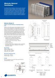
Skyflow SSMF Installation and Maintenance Instructions - Elta Fans
Skyflow SSMF Installation and Maintenance Instructions - Elta Fans
Skyflow SSMF Installation and Maintenance Instructions - Elta Fans

You also want an ePaper? Increase the reach of your titles
YUMPU automatically turns print PDFs into web optimized ePapers that Google loves.
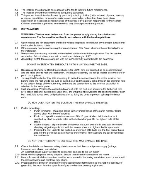
1.7 The installer should provide easy access to the fan to facilitate future maintenance.1.8 The installer should ensure the fan is adequately supported.1.9 This product is not intended for use by persons (including children) with reduced physical, sensoryor mental capabilities, or lack of experience <strong>and</strong> knowledge, unless they have been givensupervision or instruction concerning use of the product by a person responsible for their safety.Children should be supervised to ensure that they do not play with the product.2.0 INSTALLATIONWARNING – The fan must be isolated from the power supply during installation <strong>and</strong>maintenance. The fan must be earthed in accordance with the local regulations.2.1 Upon receipt, the fan equipment should be visually inspected to check for any damage. Ensure thatthe impeller is free to rotate.2.2 If there are any queries concerning the fan equipment, <strong>Elta</strong> <strong>Fans</strong> Ltd should be contacted prior tothe installation.2.3 The fan must be securely mounted in the desired position to suit the application. The fan can bemounted on flat or inclined roofs with a maximum pitch angle of 35 o .2.4 Assembly: <strong>SSMF</strong> fans are supplied with the fan/motor fully assembled to the base/cowl.DO NOT OVERTIGHTEN THE BOLTS AS THIS MAY DAMAGE THE BASE.2.5 Backdraught shutters: Backdraught shutters for <strong>SSMF</strong> fans are supplied as an assembled unit<strong>and</strong> are fitted prior to roof unit installation. The shutter assembly top flange locates onto the curb orpurlin box top face.2.6 Having fitted the shutter tray, it is necessary to make the connections to the motor terminal boxbefore fitting the roof unit to the curb or purlin box. Feed the supply cable through the grommet holein the bottom flange of the shutter tray <strong>and</strong> make the connections to the terminal box which isattached to the motor plate.2.7 Curb mounting: Position the assembled roof unit onto the curb <strong>and</strong> secure to the timber sill withM10 coach bolts (not supplied by <strong>Elta</strong> <strong>Fans</strong>), ensuring that fibre washers are positioned under eachbolt head. It is advisable to drill pilot holes prior to fitting the bolts to prevent splitting the timbercurb.DO NOT OVERTIGHTEN THE BOLTS AS THIS MAY DAMAGE THE BASE.2.8 Purlin mounting:• Purlin trimmers: - should be bolted to the vertical flange of the purlin member takingcare to align with the roof opening.• Purlin box: - position onto trimmers <strong>and</strong> fit M10 type ‘A’ short tail lindaptors (notsupplied by <strong>Elta</strong> <strong>Fans</strong>) into holes in the bottom flanges. Do not tighten nuts at thisstage.• Soaker sheets: - slip the soaker sheet over the purlin box <strong>and</strong> fix <strong>and</strong> seal to the roofsheeting. Align the purlin box with the soaker sheet <strong>and</strong> tighten the lindaptor nuts.• Position the roof unit into the purlin box <strong>and</strong> insert M10 bolts into the four corner holes<strong>and</strong> into the purlin box captive fixings ensuring that fibre washers are positioned underthe bolt heads.DO NOT OVERTIGHTEN THE BOLTS AS THIS MAY DAMAGE THE BASE.2.9 Check the details on the motor rating plate to ensure that the correct power supply (voltage,frequency <strong>and</strong> phase) is available.An incorrect power supply will lead to permanent damage to the fan motor.2.10 Refer to the appropriate wiring diagram. Ensure that all earth connections are made.2.11 Means for electrical disconnection must be incorporated in the wiring installation in accordance withthe relevant wiring <strong>and</strong> electrical regulations.2.12 Precaution must be taken to locate the exhaust discharge terminal so as to avoid the backflow ofgases into the room from the open flue of gas or other fuel burning appliances.