Field Specs & Assembly Instructions
Field Specs & Assembly Instructions
Field Specs & Assembly Instructions
- No tags were found...

Create successful ePaper yourself
Turn your PDF publications into a flip-book with our unique Google optimized e-Paper software.
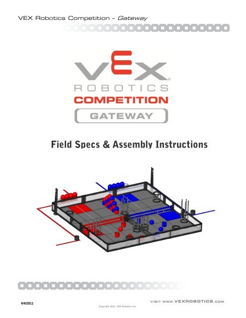
VEX Robotics Competition – Gateway<strong>Field</strong> OverviewThe game VEX Gateway is played on a 12 ft x 12 ft foam-mat, surrounded by a sheet-metal and lexanperimeter. The field is divided into three sections by a stationary fence and two gates which are raisedduring match play. Attached to the fence and to the field perimeter are circular goals which robots mayplace game objects into. Spread around the field, and in the alliance starting positions are plastic ballsand barrels. For more details and specific game-play rules, please refer to the VEX Gateway competitionmanual.4/4/2011Copyright 2011. VEX Robotics Inc.
VEX Robotics Competition – Gateway4/4/2011Copyright 2011. VEX Robotics Inc.
VEX Robotics Competition – Gateway4/4/2011Copyright 2011. VEX Robotics Inc.
VEX Robotics CompetitionGame Objects & <strong>Field</strong> Bill of MaterialsAll these items are available for purchase from:www.VEXROBOTICS.comGeneric <strong>Field</strong> Elements - Reuseable Each YearPart Number Description Price278-1501 VRC <strong>Field</strong> Perimeter Frame & Hardware $ 799.99278-1502 VRC Foam <strong>Field</strong> Surface - (36) Grey, (2) Red, (2) Blue Tiles $ 189.99275-1401 VRC VEXnet <strong>Field</strong> Controller $ 199.99Total Price $ 1,189.97Official VEX Gateway Specific ElementsPart Number Description Price276-1355 ALL Official VEX Gateway <strong>Field</strong> & Game Objects $ 499.99(1) Fence <strong>Assembly</strong>(2) Lifting Gate Asseblies(9) Circular Goals(1) Roll 2" Wide Red Tape(1) Roll 2" Wide Blue Tape(1) Roll 3/4" Wide White Tape(13) Red, (13) Blue, (2) Black, & (2) White Barrels(9) Red & (9) Blue Balls(40) Red & (40) Blue Robot Identification FlagsTotal Price $ 499.99Practice ElementsPart Number Description Price276-2102 VEX Gateway Goal & Object Kit $ 49.99(2) Red & (2) Blue Barrels(2) Red & (2) Blue Balls(1) 30" Tall Circular Goal -- includes (2) Goal Rings & (5) 30" Posts
VEX Robotics Competition – Gateway<strong>Field</strong> SpecificationsIntroductionThis section will outline the specifications which are most important to teams designing a robot tocompete in the VEX Robotics Competition – Gateway. Though many of the critical dimensions areincluded in this section, it may be necessary to consult the separate assembly guide and 3D-CAD modelsof the field for an additional level of detail (if you can’t find a dimension in the specifications, we include aFULL model of the field – virtually measure whatever you need).<strong>Field</strong> components may vary slightly from event to event. This is to be expected; teams will need to adaptaccordingly. It is good design practice to create mechanisms capable of accommodating variances in thefield and game pieces.4/4/2011Copyright 2011. VEX Robotics, Inc.
140.50Inside Wall - Wall1.274Wall Thickness140.50Inside Wall - Wall11.328Wall HeightFrom FoamSurface<strong>Field</strong> Critical Dimensions:• ~140.5" Square Wall-Wall, Inside• 11.328" Wall Height• 1.27" Wall ThicknessFoam FloorDescriptionDwg NoCompetition<strong>Field</strong> Perimeter DetailsVRC12-FIELD-SPECS REV1VRC - Gateway Sheet 1 of 10Release2/15/2011ALL DIMENSIONS ARE IN INCHES.
There are nine (9) barrels and five (5) balls of each color on the field, not including pre-loadsand match loads. Additionally, there are two (2) black barrels and two (2) white barrels.Game Object dimensions may vary by as much as 1/4".6.000AR3.0005.0001.342A6.000SECTION A-ASCALE 1 : 3Each Barrel weighs approximately0.53 lbs. and each Ball weighsapproximately 0.24 lbs.DescriptionDwg NoCompetitionGame Object DetailsVRC12-FIELD-SPECS REV1VRC - Gateway Sheet 2 of 10Release2/15/2011ALL DIMENSIONS ARE IN INCHES.
1.0481.00011.500R5.2159.115R3.91272°DescriptionDwg NoCompetition11.5" High Goal DetailsVRC12-FIELD-SPECS REV1VRC - Gateway Sheet 3 of 10Release2/15/2011ALL DIMENSIONS ARE IN INCHES.
1.0481.7345.2361.00020.000R5.2159.115R3.91272°DescriptionDwg NoCompetitionFence Goal DetailsVRC12-FIELD-SPECS REV1VRC - Gateway Sheet 5 of 10Release2/15/2011ALL DIMENSIONS ARE IN INCHES.
60.9577.50031.832 29.1258.97511.250Fence7.4553.330Gate61.8758.00011.00071.8132.678Fence70.0534.089 4.089Gate5.7502.178DescriptionDwg NoCompetitionFence and Gate DetailsVRC12-FIELD-SPECS REV1VRC - Gateway Sheet 7 of 10Release2/15/2011ALL DIMENSIONS ARE IN INCHES.
The Balls and Barrels are placed on the field in as follows for the start of each match.1. There are three (3) barrels and two (2) balls of the corresponding color within each ofthe Isolation Zones.2. There are six (6) barrels and three (3) balls of each color assembled into a wall in thecenter of the Interaction Zone.3. There are four (4) balls and four (4) barrels available for match and/or preloads withinthe driver station of each alliance.(1)(3)(2)Center StackBalls and Barrels are placed at the junction of Foam <strong>Field</strong> Tiles, or at the centerof tiles as shown.DescriptionDwg NoCompetitionGame Object LayoutVRC12-FIELD-SPECS REV1VRC - Gateway Sheet 8 of 10Release2/15/2011ALL DIMENSIONS ARE IN INCHES.
The Goal are placed in nine (9) locations and are of three (3) heights.1. 11.5" High Goals, mounted to the field perimeter.2. 20" High Goals, mounted to the Fence Pipes.3. 30" High Goals, mounted to the field perimeter.4. 30" High Goal, mounted to the Center Post.(1) (1)(4)(3) (3)(2) (1)DescriptionDwg NoCompetitionGoal LayoutVRC12-FIELD-SPECS REV1VRC - Gateway Sheet 9 of 10Release2/15/2011ALL DIMENSIONS ARE IN INCHES.
VEX Robotics Competition – Gateway<strong>Field</strong> <strong>Assembly</strong>IntroductionThis section will detail the steps required to construct the competition field for the VEX RoboticsCompetition Gateway. The VRC Gateway field utilizes the “VEX Competition <strong>Field</strong> Perimeter” (278-1501). For specifications and instructions for assembling this frame, please refer to the separate “VEXCompetition <strong>Field</strong> Perimeter” manual.Also refer to the separate low-cost field document, which provides lower cost options to teams notneeding a full “official” competition field.Tools RequiredThe following tools are required for assembly of the official VEX Gateway field:• 5/32” Allen Wrench• 7/16” Open Ended Wrench• #2 Phillips Screwdriver (or drill with #2 Phillips Bit)• 3/32” Allen Wrench (standard VEX Allen Wrench)• 11/32” Open Ended Wrench (standard VEX Open Ended Wrench)4/4/2011Copyright 2011. VEX Robotics, Inc.
DRIVER STATION POSTSVL-FIELDFIELD PERIMETERFOAM FLOORASSEMBLYCROWD VIEWNotes:1. Assemble the VL-FIELD Perimeter (see seperate VL-FIELD assembly instructions.)Position the perimeter such that one side is toward the crowd.2.3.Attach the Driver Station Posts as shown below (in the middle of the foam tile farthestfrom the crowd). <strong>Instructions</strong> for assembly are included with the VL-FIELD instructions.Assemble the Foam Floor inside the perimeter.Refer to Sheets 2 & 3 of this document for instructions.IMPORTANT:It is important to assemble the field on a flat, levelsurface. Some venues may wish to installfloor protection underneath the field.DescriptionDwg NoProject CompetitionPerimeter PlacementVRC12-FIELD-ASSY REV1VRC - GatewaySheet 1 of 17Release2/15/2011ALL DIMENSIONS ARE IN INCHES.
Before assembling the foam tile floorsome tiles will need to be modified.There are 3 main types of tiles.(16X) Normal TilesNormal tiles, are unmodified. Thesewill be used on the "inside" of thefield. There should be sixteen(16) ofthese per field.(4X) Corner TilesCorner tiles have their interlockingtabs cut away on two (2) adjacentedges. These will be used in the four(4) corners of the field.(16X) Edge TilesEdge tiles have their interlockingtabs cut away on one (1) edge.These will be used along the edgesof the field. There are sixteen (16)per field.Tabs should be easily removed with a sharpknife or razor blade. When the tiles areassembled, there should be a smooth edgearound the entire perimeter.IMPORTANT:Before modifying ANY tiles, check to ensureyour set of tiles NEEDS modification.DescriptionDwg NoCompetitionFoam Tile ModificationVRC12-FIELD-ASSY REV1VRC - Gateway Sheet 2 of 17Release2/15/2011ALL DIMENSIONS ARE IN INCHES.
CE E E ECENNNNEEN N N NEENNNNEEN N N NECEEEECN = Normal Tile (16X)C = Corner Tile (4X)E = Edge Tile (16X)Assemble Foam Tiles as shown above.The "smooth" side of the tiles should be up, and the textured side down.The tiles should be assembled "in-place", within the field perimeter.The grid-lines shown are for reference only.DescriptionDwg NoCompetitionTile Floor <strong>Assembly</strong>VRC12-FIELD-ASSY REV1VRC - Gateway Sheet 3 of 17Release2/15/2011ALL DIMENSIONS ARE IN INCHES.
36.00012.00059.760106.76012.00036.000Once the <strong>Field</strong> Perimeter is in its final position, mark off the Driver Stations usingred and blue tape. One station should be blue, and one should be red.Apply the tape as shown above. Do not close the back of the driver-boxes.The Driver Stations should extend to the edges of its corresponding colored tiles.DescriptionDwg NoCompetitionDriver Station LayoutVRC12-FIELD-ASSY REV1VRC - GatewaySheet 4 of 17Release2/15/2011ALL DIMENSIONS ARE IN INCHES.
WHITE ELECTRICAL TAPE3/4" WIDEWHITE ELETRICAL TAPE3/4" WIDEIMPORTANT:Apply tape carefully and slowly for best result.Smooth out all bubbles.Do not "stretch" the tape as it is applied!WHITE ELECTRICAL TAPE3/4" WIDEThere are nine (9) lines stretching across the playing field. These linesare used for robot line following, and to indicate the Low Goals. Thetape is layed out on the field as shown above. The lines are madefrom 3/4" wide white electrical tape.Apply the tape lines as shown. They should lay on top of the foamtile's seams or centers.DescriptionDwg NoCompetitionTape Line LayoutVRC12-FIELD-ASSY REV1VRC - GatewaySheet 5 of 17Release2/15/2011ALL DIMENSIONS ARE IN INCHES.
PLACEMENT OF WALL BRACKETWALL BRACKETSTEP 11. Install one (1) Wall Bracket tothe VL-FIELD perimeter in thelocations shown above usingfour (4) 1/4-20 x 5/8" boltsand four (4) 1/4-20 wingnuts.STEP 2FENCE PIPE2. Slide two (2) black Fence Pipesinto the Wall Bracket andinsert two (2) 1/4" x 2-1/2" ClevisPins into the rear holes of theWall Bracket and through theFence Pipe. It is critical thatthe small holes near the centerof the Black Wall Pipe are closestto the field's center!DescriptionDwg NoCompetitionFence <strong>Assembly</strong>VRC12-FIELD-ASSY REV1VRC - Gateway Sheet 6 of 17Release2/15/2011ALL DIMENSIONS ARE IN INCHES.
3. Insert two (2) Hairpins into the 1/4-20Clevis Pins.STEP 3GATE BRACKET4. Assemble the Center Post separatelyfrom the wall. Begin by installing one(1) 1/4-20 x 1/2" bolt into the lower holeof the Gate Bracket and through thelower hole of the Center Post with one(1) 1/4-20 Keps nut. Next, insert one(1) 2-1/2" Standoff between the upperholes of the Center Post and GateBracket. Install using two (2) 8-32 x 1/2"bolts.CENTER POSTSTEP 4DescriptionDwg NoCompetitionFence <strong>Assembly</strong>VRC12-FIELD-ASSY REV1VRC - Gateway Sheet 7 of 17Release2/15/2011ALL DIMENSIONS ARE IN INCHES.
PLACEMENT OF CENTERPOST5. Place the Center Post in thelocation indicated abovewith the Gate Bracket facingaway from the Driver Stations.STEP 5STUDSIMPORTANT:It is critical that the studs on the Center Postfit into the seams of the tiles as indicated.DescriptionDwg NoCompetitionFence <strong>Assembly</strong>VRC12-FIELD-ASSY REV1VRC - Gateway Sheet 8 of 17Release2/15/2011ALL DIMENSIONS ARE IN INCHES.
6. With the Center Post in position,slide the black Fence Pipes intothe Gate Bracket. Insert two (2)1/4" Clevis Pins into the middlehole in the Gate Bracket andthrough the black Fence Pipes.STEP 67. Insert two (2) Hairpins into the1/4-20 Clevis Pins.STEP 7DescriptionDwg NoCompetitionFence <strong>Assembly</strong>VRC12-FIELD-ASSY REV1VRC - Gateway Sheet 9 of 17Release2/15/2011ALL DIMENSIONS ARE IN INCHES.
PLACEMENT OF GATE WALL BRACKETS1.As in STEP 1 of the Fence <strong>Assembly</strong>,install the Wall Brackets in thelocations indicated above.2. Slide the Gate Pipes into the WallBracket and insert the 1/4" ClevisPins into the Wall Bracket andthrough the Gate Pipes. The toppipe installs into the rear hole,and the lower pipe installs intothe front hole.GATE PIPESTEP 23. Slide the Gate Bracket into placeand insert the 1/4" Clevis Pins intothe Wall Bracket and through theGate Pipes. The top pipe installsinto the front hole, and the lowerpipe installs into the rear hole.STEP 3DescriptionDwg NoCompetitionGate <strong>Assembly</strong>VRC12-FIELD-ASSY REV1VRC - Gateway Sheet 10 of 17Release2/15/2011ALL DIMENSIONS ARE IN INCHES.
8.00012.0004. Add two tape rings to the lowerGate Pipe at the dimensionsspecified on the field perimeterside.STEP 45. Place the 14" length of one-wrapVelcro near the gate bracket.During gameplay, the Velcroshould be used in the manner asshown to secure the gate fromfalling down.VELCRO STRAP6. Repeat STEPS 1-5 for the secondgate.STEP 5DescriptionDwg NoCompetitionGate <strong>Assembly</strong>VRC12-FIELD-ASSY REV1VRC - Gateway Sheet 11 of 17Release2/15/2011ALL DIMENSIONS ARE IN INCHES.
GOAL RINGSTEP 11. Install a Goal Ring to the topblack Fence Pipe by screwing two (2)#10 x 1/2" Sheet Metal Screwsinto the small holes located nearthe center of the black Fence Pipe.20" HIGH GOAL PIPE2. Insert two 20" High Goal Pipes intothe rear holes of the Goal Ring.Continue to insert them into a secondring prior to its mounting. This ensuresconcentric goals.STEP 2IMPORTANT:Support the Goal Rings while insertingpipes to prevent breaking of the rings!Insert the pipes using a twisting motionfor the easiest installation.DescriptionDwg NoCompetitionFence Goal <strong>Assembly</strong>VRC12-FIELD-ASSY REV1VRC - Gateway Sheet 12 of 17Release2/15/2011ALL DIMENSIONS ARE IN INCHES.
STEP 11. Install two (2) Goal Rings to theCenter Post with four (4) 1/4-20x 1/2" bolts and four (4) 1/4-20Keps nuts.2. Insert five (5) 30" HighGoal Pipes into the GoalRings.IMPORTANT:Support the Goal Rings whileinserting pipes to preventbreaking of the rings! Insert thepipes using a twisting motion forthe easiest installation.STEP 2CORRECTLY ASSEMBLEDGOALDescriptionDwg NoCompetitionCenter Post Goal <strong>Assembly</strong>VRC12-FIELD-ASSY REV1VRC - Gateway Sheet 14 of 17Release2/15/2011ALL DIMENSIONS ARE IN INCHES.
PLACEMENT OF11.5" HIGH GOALS1. Install two (2) Goal Rings to theVL-FIELD perimeter in thelocations indicated above withfour (4) 1/4-20 x 5/8" bolts andfour (4) 1/4-20 wing nuts.STEP 12. Insert five (5) 11.5" High GoalPipes into the Goal Rings.IMPORTANT:Support the Goal Rings while insertingpipes to prevent breaking of the rings!Insert the pipes using a twisting motionfor the easiest installation.STEP 2DescriptionDwg NoCompetition11.5" High Goal <strong>Assembly</strong>VRC12-FIELD-ASSY REV1VRC - Gateway Sheet 15 of 17CORRECTLY ASSEMBLEDGOALRelease2/15/2011ALL DIMENSIONS ARE IN INCHES.
STEP 1PLACEMENT OF30" HIGH GOALS1. Install two (2) Goal Rings to theVL-FIELD perimeter in thelocations indicated above usingfour (4) 1/4-20 x 5/8" bolts andfour (4) 1/4-20 wing nuts.STEP 22. Insert five (5) 30" High GoalPipes into the Goal Rings.IMPORTANT:Support the Goal Rings whileinserting pipes to preventbreaking of the rings! Insert thepipes using a twisting motion forthe easiest installation.DescriptionDwg NoCompetition30" High Goal <strong>Assembly</strong>VRC12-FIELD-ASSY REV1VRC - Gateway Sheet 16 of 17CORRECTLY ASSEMBLEDGOALRelease2/15/2011ALL DIMENSIONS ARE IN INCHES.
Place the balls andbarrels on the field in thelocations shown.Refer to the VRCGateway Game Manualfor more details includingall official rules andregulations.Use the 3D CAD model ofthe VRC Gateway fieldfor additional details notshown in the <strong>Field</strong>Drawings.CENTER STACKDescriptionDwg NoCompetitionGame Object LayoutVRC12-FIELD-ASSY REV1VRC - Gateway Sheet 17 of 17Release2/15/2011ALL DIMENSIONS ARE IN INCHES.