DuoTherm Dometic 59146 Roof-Top Heat Pump ... - Dutchmen RV
DuoTherm Dometic 59146 Roof-Top Heat Pump ... - Dutchmen RV
DuoTherm Dometic 59146 Roof-Top Heat Pump ... - Dutchmen RV

You also want an ePaper? Increase the reach of your titles
YUMPU automatically turns print PDFs into web optimized ePapers that Google loves.
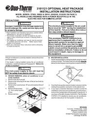
a) Remove upper duct from ceiling template andlocate it over blower discharge.NOTE: Edges without flanges install toward REAR andSIDE of opening.b) Use two (2) sharp pointed #10 x 1/2" sheet metalscrews (A) to hold duct to base pan. Holesprovided in bottom of basepan for these screwsto go into.2) Check for correct alignment and adjust the unit asnecessary (<strong>Roof</strong> Gasket centers over 14" opening).3) Reach up into return air opening of the air conditionerand pull the unit electrical cord down for laterconnection.4) Measure the ceiling to roof thickness:CENTER A /CFROM BEL OWGASKET! CAUTIONDO NOT slide the unit. This may damage the neoprenegasket attached to the bottom and create a leakyinstallation.MEASURECEILINGTHICKNESSPULL DOW NELECTRICAL CORD4) Place the Air Box Kit inside the <strong>RV</strong>. This boxcontains mounting hardware for the air conditionerand will be used inside the <strong>RV</strong>.This completes the outside work. Minor adjustments canbe done from the inside if required.E. DISCHARGE DUCT AND CEILINGTEMPLATE1) Remove air box and mounting hardware fromcarton. The upper duct is shipped inside the lowerduct which is part of the ceiling template.FRONT O FCOACHUPPERLOWERAASIDE W ITHOUTTAB T O R EAR A NDSIDE OF A IRCONDITIONERa) If distance is 1"-2", remove perforated tabs fromboth upper and lower ducts.b) If distance is 2"-3", remove perforated tabs frombottom duct only.c) If distance is 3"-4", install ducts as received.d) If distance is 4"-6", use optional duct adaptor,Part No. 313606.000 and Bolt Kit, Part No.3100895.006.5) Install ceiling template by sliding lower duct overupper duct.6) Start each mounting bolt by hand before tighteningany of them. The four (4) threaded inserts in thebase pan can be seen to aid in starting the bolts.EVENLY TIGHTEN MOUNTING BOLTS TO ATORQUE OF 40 TO 50 INCH POUNDS.This will compress the roof gasket to approximately1/2". The bolts are self locking so overtightening is not necessary.7) Install wood screws (C) in each end of ceilingtemplate and into junction box. This insures a tightfit of air box to ceiling.F. CONNECTION OF POWER SUPPLYNOTE: All wiring must comply with the NationalElectrical Code and any State or Local Codesor regulations.1) Route supply line into junction box thru providedRomex Connector. Six (6) inch leads are sufficientfor connection to unit wires and ground screws.6