service manual for 6700, 7000, 8000 & 9000 series air conditioners
service manual for 6700, 7000, 8000 & 9000 series air conditioners
service manual for 6700, 7000, 8000 & 9000 series air conditioners
- No tags were found...

Create successful ePaper yourself
Turn your PDF publications into a flip-book with our unique Google optimized e-Paper software.
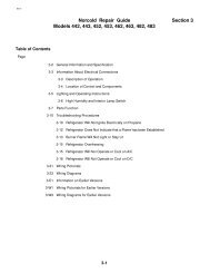
TABLE OF CONTENTSBasic Components and Their FunctionsRefrigeration System DiagramI. Refrigeration Circuit . . . . . . . . . . . . . . . . . . . . . . . . . . . . . . . . . . . . . . . . . . 5II. Air Handling Circuits . . . . . . . . . . . . . . . . . . . . . . . . . . . . . . . . . . . . . . . . . 6III. Electric Power Circuits . . . . . . . . . . . . . . . . . . . . . . . . . . . . . . . . . . . . . . . . 6IV. Tools And Equipment . . . . . . . . . . . . . . . . . . . . . . . . . . . . . . . . . . . . . . . . . 10V. Service Problems And Their Solutions . . . . . . . . . . . . . . . . . . . . . . . . . . . . 13VI. Typical Wiring Diagrams . . . . . . . . . . . . . . . . . . . . . . . . . . . . . . . . . . . . . . 20QUICK DIAGNOSIS CHARTNote: This charge represents problems with units having mechanical controls - if the <strong>air</strong> conditioneris equipped with a wall thermostat, please refer to the appropriate <strong>manual</strong>.Problem Possible Causes Ref. Page NumberFan And Compressor Will Not Run No Power 115V 14Selector Switch 14Fan Will Not Run Selector Switch 17Fan Run Capacitor 17Motor 17Wiring (Mis-wired) 20-21Compressor Will Not Run Selector Switch 15Thermostat 15Low Voltage 15Overload 15Compressor 15Wiring (Mis-wired) 20-21PTCR or Potential Relay 16-17Start Capacitor 20-21Run CapacitorCooling Per<strong>for</strong>mance 19
BASIC COMPONENTS AND THEIR FUNCTIONSREFRIGERATION SYSTEM DIAGRAMDISCHARGELINESUCTIONLINECOMP.CONDENSERFANFANMOTOREVAPORATOREVAPORATORBLOWERCONDENSER COILHIGH SIDELOW SIDE4
5. Suction LineThe suction line is the tube which carries the superheatedvapor refrigerant from the evaporator to the compressor.6. CompressorThe compressor is called a hermetic compressor which meansthat it is completely sealed (welded together). It is, there<strong>for</strong>e,not internally field <strong>service</strong>able. Inside the compressorhousing are basically:a) an electric motor which drives the compressor,b) a pump which is designed to pump superheatedvapor only,c) a supply of special refrigeration oil. A small portionof the oil will circulate out through the system withthe refrigerant, but will constantly return to thecompressor with the refrigerant, so the compressorwill not run out of oil.7. Discharge LineThe discharge line carries the refrigerant out of thecompressor and to the condenser coil. Remember that as therefrigerant entered the compressor, it was superheated vapor.The refrigerant enters the compressor, where more heat isadded and is compressed into a smaller space. Therefrigerant, there<strong>for</strong>e, leaves the compressor highlysuperheated – so if the discharge line is hot to the touch(burns), don’t be surprised – it should be.8. Condenser CoilThe purpose of the finned condenser coil is to transfer heatfrom the high pressure refrigerant to the warm outdoor <strong>air</strong>.As the outdoor <strong>air</strong> passes over the coil, the heat transfer willcause the <strong>air</strong> temperature to rise. Thus the condenserdischarge <strong>air</strong> will be several degrees warmer than thecondenser entering <strong>air</strong>.As the refrigerant passes through the first few tubes of thecondenser, its temperature will be lowered or it will be desuperheated.After the refrigerant is de-superheated, it willbegin to condense or change from a vapor to a liquid and willremain at a nearly constant temperature throughout almost allof the remainder of the coil. This temperature is called thecondensing temperature or high side saturation temperatureand will always be higher than the condenser entering <strong>air</strong>temperature.Near the bottom of the condenser, the refrigerant will all becondensed to a liquid and from there on its temperature willdrop to more nearly the temperature of the outdoor <strong>air</strong>. Afterthe temperature of the refrigerant drops below condensing orsaturation temperature, we call its condition sub-cooledliquid.During all of the three processes in the condenser (desuperheating,condensing, sub-cooling), the refrigerant givesup heat; but most of the heat is given up during thecondensing process.II. AIR HANDLING CIRCUITS1. Motors and FansOne motor turns both the condenser fan blade and evaporator<strong>air</strong> blower. The condenser (outdoor) fan is an axial flow(propeller) type and the evaporator (indoor) fan or blower is acentrifugal (squirrel cage) type.2. FiltersThe filters should always be in place when the system isrunning. More important than their purpose of cleaning the<strong>air</strong> in the living space is the protection the filters give theevaporator coil. Without filters, a wet evaporator coil willquickly stop up so that adequate <strong>air</strong> cannot pass through it.Filters must be installed to completely fill the filter rack sothat no <strong>air</strong> can flow around them or by-pass them and carrydust, lint, etc. to the evaporator. To clean an evaporator thathas not been properly protected by its filter, the entire unitmust be removed from the recreational vehicle and the coilcleaned with special detergent and water.III. ELECTRIC POWER CIRCUITS1. SafetyVoltage (electrical pressure), whether high or low, will nothurt you. It is the current through vital parts of your bodythat does the damage, and under the right conditions, 115volts (domestic USA) is plenty to drive a deadly dose ofcurrent (amperes) through your body.Another imminent danger from electric shocks in addition toelectrocution is reaction. An electrical shock causesuncontrollable muscular contractions which can cause furtherinjuries.Remember that electricity can be very dangerous, but you cansafely work with it. In order to be safe, you must know whatyou are doing. You must work deliberately and carefully.You must think safety be<strong>for</strong>e each move.THINK SAFETY2. Power Supply - from Commercial Utility1) Wire Size6
condition can be analyzed by using an ohm meter. Be sure toremove all the leads from the compressor terminals be<strong>for</strong>emaking this check.1) If the resistance between any two terminals is 0ohms, the motor windings are shorted.2) If the resistance between any terminal and thecompressor housing is anything but infinity, thewinding is grounded.3) If the resistance between any two terminals isinfinity, the winding is open.On a good compressor, the highest resistance will be betweenthe R (run) and S (start) terminals. The lowest resistance willbe between the C (common) and R (run) terminals. Theintermediate resistance will be between the C (common) andS (start) terminals. Notice that compressors have theidentification of the terminals marked on either the terminalcover or on the compressor housing.7. Overload Switchthrough the condenser coil.* Some models use a squirrel cage on both ends of the motor.An important step in installing a replacement fan motor is tocheck the direction of rotation be<strong>for</strong>e it is installed. On allmodels, the condenser fan pulls the <strong>air</strong> through the coil.Fan Motor Check ProcedureIf a fan motor refuses to per<strong>for</strong>m properly, it can be checkedin the following manner:9. Be sure the motor leads are connected to the properpoints –a) The black wire from the motor connects to ablack wire inside a wire nut then the blackwire connects through the disconnect plugto the selector switch. The red wire fromthe motor connects to a red wire in a wirenut then the red wire connects through thedisconnect plug to the selector switch.Mounted on the outside of the compressor housing is a twoterminal overload switch. Note: We have a few models withinternal overloads that are non-<strong>service</strong>able. The switch isconnected in <strong>series</strong> with the common terminal, so if theswitch opens, it will cut the power to the compressor motor.The switch will open as the result of either or both of twoconditions that could be harmful to the compressor.1) High Amperes (Current)The switch contains a heater which increases in temperatureas the current increases. The higher temperature warps theswitch and will cause it to open be<strong>for</strong>e the windings reach adangerous temperature.2) High Temperature (Thermal)The switch is clamped tightly against the compressor housingand located close to the windings. There<strong>for</strong>e, as the windingsreach a higher temperature, it takes less current to cause theswitch to open.As can be seen, the switch is always affected by acombination of current to the compressor and windingtemperature.8. Fan MotorThe <strong>air</strong> conditioning unit has one double end shaft fan motor.On one shaft end is mounted a centrifugal or squirrel cageblower which draws <strong>air</strong> (return <strong>air</strong>) out of the recreationalvehicle and blows the conditioned <strong>air</strong> down into therecreational vehicle. On the other end is mounted an axialflow or propellor type fan which circulates outdoor <strong>air</strong>b) The white wire from the motor connects tothe fan capacitor or a white wire in a wirenut then the white wire connects throughthe disconnect plug to the thermostat.c) The brown wires from the motor connect tothe fan capacitor.2. To check the motor winding resistance carefully,check the resistance between each of the wires andground (preferably a copper refrigerant tube <strong>for</strong> agood connection). These readings must be infinity.Any continuity means the windings are grounded.If there is a reading of 0 between any two leads, themotor is shorted and is no good. If there is a readingof infinity (no meter reading at all) between any twoleads, the winding is open and the motor is no good.Note:A motor with 2 brown leads will have anO reading between 1 brown wire and eitherthe black or white wire.8
9. Run CapacitorsThe purpose of the run capacitors is to give the motorsstarting torque and to maintain high power factor duringrunning. The run capacitors are always connected betweenthe start and run or main terminals of the motor.On some older models, one of the terminals of the runcapacitors will have a red dot (the identified terminal). Theidentified terminal should always be connected to the run ormain terminal of the motor and to the neutral line.CAPACITORSGood CapacitorIf the capacitor is good, the indicator will move from infinity(the left side), towards zero ohms and slowly return back toinfinity. Reverse the leads and test again. The result shouldbe the same.OHM METERCAPACITORCapacitor CheckThere are several capacitor test devices available. The ohmmeter is one of them. The ohm meter cannot verify acapacitors MFD (microfarrad) value. However, the followingprocedures will show you how to use an ohm meter todetermine if the capacitor is good, open, shorted or grounded.Be<strong>for</strong>e testing any capacitor, always per<strong>for</strong>m the followingprocedure:* This test must be done with a analog type meter.a) Disconnect all electrical power to the <strong>air</strong> conditioner.b) Discharge the capacitor with a 20,000 ohm (approx.3 watt) resistor or larger.c) You may discharge capacitors with a standard voltmeter if you use a scale over 500 volts and touch theleads (one lead to each side of the capacitor). Thevolt meter will discharge the capacitor.HIGHOpen CapacitorOKLOWIndicator sweeps back and <strong>for</strong>thas shown above. Capacitor is good.If the capacitor is open, the indicator will show no deflectionor movement. Reverse the leads and test again. If there is noindicator movement on the second test, the capacitor is open.Open capacitors are defective and must be replaced.OPENHIGH LOWd) Identify and disconnect the wiring from thecapacitor.e) Set and zero the ohm meter on the “highest” scale.When testing <strong>for</strong> a good, open or shorted capacitor,per<strong>for</strong>m the following checks: Place the ohm meterleads across the capacitor terminals (one lead oneach terminal) and per<strong>for</strong>m a continuity test. Thenobserve the action of the meter needle or indicator.Reverse the leads and test again. The result shouldbe the same. Note: If the capacitor had not beenproperly discharged, a false reading could beindicated on the first test. Always test several times(reversing the leads with each test). This will verifythe capacitors condition.Shorted CapacitorIndicator shows no movement.Needle stays to the left side. If needleshows no movement after reversing theleads, the capacitor is open.If the capacitor is shorted, the indicator will move towards and sometimes hit zeroohms, and will stay there. This indicates a completed circuit through the inside ofthe capacitor (shorted). Shorted capacitors are defective and must be replaced.SHORTHIGH LOWIndicator moves to the right sideof the scale and stays there(indicating a completed circuit).The capacitor is shorted.9
Grounded CapacitorWhen testing <strong>for</strong> a grounded capacitor, per<strong>for</strong>m a continuitycheck between each terminal on the capacitor and the baremetal of the capacitor case. Any indication of a circuit(constant resistance) from either terminal to case, indicates agrounded capacitor. Grounded capacitors are defective andmust be replaced.CAPACITORconnected in <strong>series</strong> with the start winding and it getsthe generated voltage of the start winding portion ofthe compressor motor. This generated voltage ismuch higher than line voltage and varies with thespeed of the motor. There<strong>for</strong>e, since the relay isdesigned to open the contacts at 75% of normalrunning voltage (measured between terminals #5 and#2), the contacts will open (thus disconnect the startcapacitor) at approximately 75% of normal runningspeed.11. (B) Positive Temperature Coefficient Resistor(Commonly Known As PTCR StartDevice)OHM METERHIGHGROUNDEDLOWThe resistor acts like a potential relay in that it takes the startcapacitor out of the start circuit, but uses resistance ofelectrical flow (back EMF from compressor) instead ofopening a set of contacts. The <strong>service</strong> person should be carefulhandling the resistors. They will be hot during operation (upto 160 degrees F). The <strong>air</strong> conditioner needs to be off <strong>for</strong> 3-5minutes during cycle time and when servicing to let theresistor cool down.12. Heating Element10. Start CapacitorIndicator moves to the right side ofthe scale and stays there(indicating a completed circuit).The capacitor is grounded.Most models use a start capacitor and a start relay to give thecompressor high starting torque. The compressor will,there<strong>for</strong>e, start against normal pressure difference (headpressure minus suction pressure) even when shut down <strong>for</strong> ashort period of time. The start relay will disconnect the startcapacitor when the motor reaches approximately 75%running speed.11. (A) Start (Potential) RelayThe start relay consists of –1) Normally closed contacts internally betweenterminals #1 and #2 which switch in the startcapacitor in parallel to the run capacitor during shutdown and then switch out the start capacitor whenthe motor reaches approximately 75% normalrunning speed.2) A high voltage coil internally between terminals #5and #2 to actuate the contacts. The coil is too weakon line voltage to actuate the contacts, but it isThe heating element is a resistance heater of 1600 watts (5600BTUH) capacity and is connected across the line when theselector is set <strong>for</strong> heating and the thermostat is calling <strong>for</strong> heat.The current draw of the heater (element only) will be 13.3amperes at 120 volts (domestic USA models).13. Limit SwitchThe limit switch is a safety switch and is mounted in theheating element frame. It will open and break the circuit ontemperature rise in case the <strong>air</strong> flow through the heaterbecomes low enough to cause the heater to overheat.IV. TOOLS AND EQUIPMENTIn order to <strong>service</strong> the equipment covered by this ServiceManual, a technician will need all the common mechanicstools such as wrenches, screwdrivers, hammers, etc.In addition to the common mechanics tools, in order to dorefrigeration and electrical work, he will need special tools andequipment such as:1. Ammeter2. Ohm Meter3. Volt Meter4. Refrigerant Recovery Equipment5. Charging Cylinder6. Vacuum Pump7. Vacuum Gauge8. Leak Detector9. Brazing Equipment10. Gauge Manifold10
1. Ammeter And Its UseAn ammeter is an instrument <strong>for</strong> measuring electric current.Current electricity is actually electrons moving from one atomto another through a conductor. In order to intelligently useelectricity, we must have a measurement of a quantity ofelectrons.The instrument we use to measure the number of amperes iscalled an ammeter. These instruments have snap-aroundjaws that will allow you to read the current through a wirewithout detaching the wire from the system. Always buy anenergizer with the instrument so that you can accurately readlow current circuits. These meters also have volt meter andohm meter attachments so they are an excellent multi-purposemeter. NO TECHNICIAN SHOULD EVER ATTEMPT ASERVICE CALL WITHOUT ONE.2. Ohm Meter And Its UseAn ohm meter or resistance meter indicates the resistance of acircuit to current flow. Just as every water pipe or hose has aresistance to water flow or every <strong>air</strong> duct has resistance to <strong>air</strong>flow, so does every wire have resistance to the flow of electriccurrent. There is no such thing as a conductor with zeroresistance to electron flow although sometimes we will bemeasuring the resistance of a conductor and find it so lowthat we cannot detect any resistance; so we call the resistancezero. What we mean is that the resistance is so low that wecan’t find it. The amount of resistance or holding back <strong>for</strong>ceof the wire or conductor depends on:a) The material the conductor is made of; silver, copperand aluminum are good conductors. This means thatin any given size wire, these materials will have lowresistance. Silver has the lowest resistance, but itsprice is too high, so we use copper.b) The diameter of the wire. The longer the wire, thegreater the resistance because there is more metal tocarry the current.c) The length of the wire. The longer the wire, thegreater the resistance. In fact, the resistance of anywire varies in direct ratio with its length.d) The temperature of the conductor. The resistance ofmost - but not all - conductors increases as thetemperature of the conductor rises. Hence, theresistance of the filament of a light bulb is rather lowwhen it is turned off and cooled down; but when thepower is turned on, the filament temperatureincreases until it glows and the resistance increases.Resistance to electron flow is measured in units called ohms.An ohm is actually the amount of resistance that will hold thecurrent down to one ampere (one coulomb of electrons persecond) if there is one volt of pressure.An ohm meter is really a resistance meter that is calibrated inohms. The ohm meter has its own power source, a small drycell, which <strong>for</strong>ces a small amount of current through aconductor via the meter probes. The meter must be calibratedto read 0 ohms when the probes are touched together each timeit is used because as the dry cell loses its charge, the meter willget out of calibration.If the probes of an ohm meter are attached to the terminals of aclosed switch, the meter will read 0. This means that there isvirtually no resistance to current flow through the switch.Now, if the switch is turned off, the contacts will be open andthere will be very high resistance. In fact, the resistance is sohigh it is an infinite number of ohms so we call this readinginfinity.With the switch open, there is not a continuous conductorthrough it so we say there is no continuity. If the ohm meterreads anything other than infinity, we say we do havecontinuity. As can be seen from the above example, an ohmmeter is a good instrument <strong>for</strong> checking to see if the contactsof a switch, thermostat, relay, overload, etc. are closingproperly or creating continuity.The previous examples show two conditions that can bedetected by an ohm meter; (1) a closed, 0 resistance conductorand (2) an open circuit which reads infinity or no continuity.Now let’s consider something in between – the windings of acompressor. If we attach the ohm meter probes to the commonand run terminals of the compressor, we can read theresistance of the main or run winding. The winding is a solidand continuous copper wire so there will be continuity throughit; but instead of 0 ohms, as there was through the closedswitch, this winding is of such small wire and so long thatthere is resistance. Now let’s attach the probes to the commonand start terminals to get the resistance of the start of phasewinding. Since this winding is made of even smaller andlonger wire, its resistance will be greater than the mainwinding. Now let’s attach the probes to the start and runterminals to read the resistance through both windings. Thisreading is the same number of ohms as the total of the twoprevious readings.If the reading between any two terminals is infinity, we candetermine that the winding is open – the wire is broken orburned in two. If the reading between any two terminals is 0ohms, the insulation is burned off the winding and we candetermine that the compressor motor is shorted. If the readingbetween any terminal and the compressor housing is anythingexcept infinity, we can determine that the compressor motor isgrounded. An open, shorted or grounded compressor must bereplaced. The fan motor windings can be checked by the samemethod as the compressor motor winding. The only differencebeing that the windings are made of smaller gauge wire andthe resistance will be higher. The fan motor has no push on11
terminals, but we know by referring to the wiring diagram,that the black wire is the common terminal, the red wire isthe start terminal and the white wire is the run terminal.Notice that when we are using an ohm meter, the power mustbe turned off. It is also important to disconnect all wiresfrom a conductor being checked with an ohm meter toprevent any chance of feedback.An Ammeter is an essential instrument to have and use, andis a real bargain because it is three instruments in one.3. Volt Meter And Its UseA volt meter measures the amount of electrical pressure in anelectrical conductor just as a tire gauge measures the amountof <strong>air</strong> pressure in an automobile tire. If we attach one voltmeter probe to the hot line and the other probe to the neutralline of a standard circuit, the meter reading will be theelectromotive (electron moving) <strong>for</strong>ce or pressure differencebetween the two lines. This is the amount of pressure wehave available to push electricity (electrons) through the lightbulbs to make the motors turn, etc. In the above example, weshould find approximately 115 volts (domestic USA models)or units of electrical pressure. Remember, a volt meteralways registers the voltage pressure difference between twopoints.CAUTIONA volt meter is used on live circuits so useextreme care. THINK SAFETY!4. Refrigerant Recovery EquipmentThe Environmental Protection Agency has implemented strictregulations on refrigerant handling and refrigerant recoveryequipment.Check with your local EPA office regarding what type ofcertification you must have to open or work on the refrigerantsealed system.In accordance to the Clean Air Act passed in 1980:1. There shall be no venting of refrigerant into theatmosphere after July 1, 1992.2. All recovery equipment must meet EPA standards(check with your local office).3. Technician Certification deadline wasNovember 14, 1993.5. Charging EquipmentThe amount of charge in any refrigerant system must be keptaccurate to within a fraction of an ounce to prevent damage tothe compressor and insure proper per<strong>for</strong>mance. Systems mustnot be charged to a certain amperage pull. They must not becharged to certain suction line temperature.The recommended field instrument <strong>for</strong> charging the rightamount of R-22 into the system is either:1. An electronic scale made especially <strong>for</strong> charging a/csystems of critical charge. (Note: The charge mustnot be weighed in with inaccurate bathroom scales,or,2. A Dial-A-Charge of 5 lb. capacity. Do not use theDial-A-Charge 10 lb. capacity or any other chargingcylinder on which the graduations of the scale aresuch that the instrument cannot be read accurately.Follow the charging cylinder manufacturer’s instructionscarefully.6. Vacuum PumpIt has long been recognized that the worst enemy of arefrigeration system is water. R-22 (and other refrigerants)will break down and change to strong acids at elevatedtemperatures in the presence of water. The greater theconcentration of water, the lower the temperature at which therefrigerant will break down. The only way to remove thewater from a system to a satisfactory level is to vaporize it anddraw it out of the system with a vacuum pump.A good quality vacuum pump is one of the finest pieces ofmachinery there is, so it deserves the best of care. Keep itclean and protected. The oil should be changed each timebe<strong>for</strong>e it is used.7. Vacuum GaugeTo go with a good vacuum pump, a good quality vacuumgauge must be used. The pump may not pump a good vacuumdue to contamination of the oil. Also a leak in the system or<strong>service</strong> hoses may prevent a deep vacuum from being reached.The length of time that it takes <strong>for</strong> the pump to evacuate asystem will vary with the amount of moisture and <strong>air</strong> in thesystem. The gauge will not show a deep vacuum (under 200microns) until all of the water has been boiled out. Also, if asystem has even a very small leak, it cannot be properlyevacuated. So a good gauge will indicate whether or not wehave a dry system with no leaks. The vacuum gauge to get is athermistor type. Remember, when you buy a gauge, it must beread accurately at 200 microns and below.8. Leak DetectorsIt is strongly recommended that a Service Technician carrytwo types of leak detectors at all times.12
1. Most all electronic leak detectors are very sensitiveand are field reliable. A word of warning – do not“give it a whiff of refrigerant” as a test to see if it isworking because its sensitivity and life expectancydiminishes as it is exposed to refrigerant.Always use this instrument as a final leak test. Itwill find the very small leaks that take several weeksto cause trouble but will cause a burn out if notrep<strong>air</strong>ed.2. With an electronic leak detector, a leak is sometimesdifficult to pinpoint – you can find the general areaof the leak, but not its exact location. A soap bubbletype leak detector will show its exact location.9. Brazing EquipmentFor all brazing work, you need a torch type that burns with asoft flame that is easy to control and is hot enough <strong>for</strong> brazingrefrigerant tubes. The easiest and most satisfactory brazingrod to use is Sil Fos or Stay Silv – 15% silver. This rod canbe used to blend with any brazing rod that exists on today’sunits.CAUTIONAlways have a dry powder fireextinguisher with you (not in your truck)while you are brazing.10. Gauge ManifoldGauge manifold sets are used <strong>for</strong> checking pressures,evacuating and recharging the a/c.Basically a gauge manifold consists of a compound gauge anda high pressure gauge mounted on a manifold with handvalves to isolate the common (center) connection or open it toeither side as desired.Connecting the gauge manifold to the system is necessary toread the suction pressure and head pressure, and tointelligently analyze a system <strong>for</strong> malfunction. Any <strong>service</strong>technician will naturally hesitate to connect his gaugesbecause to do so involves opening a hermetic system.The R-22 that is in the system will have to be released to arefrigerant recovery system (see equipment manufacturer’sguide <strong>for</strong> system access in<strong>for</strong>mation).V. SERVICE PROBLEMS ANDTHEIR SOLUTIONSWhen a recreational vehicle owner calls <strong>for</strong> <strong>service</strong> on his <strong>air</strong>conditioner, let him explain exactly what has happened; whenthe <strong>air</strong> conditioner first gave him trouble, what is soundedlike, how hot was the weather, what time was it, etc. He is arich source of in<strong>for</strong>mation. Listen to everything he says. Youwill compliment him and he will help you to identify theproblem.Always be alert <strong>for</strong> a customer who has been working on hisown equipment. Check all wiring and visually inspect allmotors, fans, capacitors, dampers, tubing, etc.When a Service Technician gets all the in<strong>for</strong>mation he canfrom the customer, he then examines the equipment <strong>for</strong> morefacts that might lead to the cause of the problem (always be onthe alert <strong>for</strong> loose or burned wires, smoke stains, kinked orbroken tubes, oil stains, etc. - those things which wouldobviously cause a malfunction or would indicate amalfunction).After he gets all the available in<strong>for</strong>mation together, he startsasking himself questions:“What causes has the in<strong>for</strong>mation eliminated and why?” (Forinstance, if the compressor is running, that eliminates atripped circuit breaker as the cause of the problem.)“What are the possible causes?”“Which of the possible causes are the most probable ones?”“How should I check them out?”For each of his questions, he expects an answer. Since there isno one else around qualified to answer his questions, he mustsupply the answers himself.As his questions and answers eliminate the possible causes oneby one, he will soon identify the reason <strong>for</strong> the malfunction.Then he can rep<strong>air</strong> it.ISOLATE THE PROBLEM – THE SOLUTION IS SIMPLE.Problem1. Nothing runs.The customer turns the selector switch to the “Cool” positionand the thermostat to a low temperature (below roomtemperature) and nothing happens. This is surely a seriousproblem, but it is usually the easiest to correct.Question:Answer:“What are the possible causes?”1. “The power supply could be dead.” Check <strong>for</strong> open circuit breaker orfuse at <strong>service</strong> panel. Check <strong>for</strong> 115 volts domestic USA models or240 volts export/overseas models between hot line (black) and neutral(white) at power entrance at unit.13
2. “The selector switch could be open.” Rotate theselector switch and check <strong>for</strong> continuity between theappropriate terminals.ProblemTerminalsSwitch PositionL-1-3Lo HeatL-1 Lo FanL-2 Hi FanL-1-4Lo CoolL-2-4Hi CoolNotice that when we are using an ohm meter, thepower must be turned off. It is also important todisconnect all wires from a conductor being checkedwith an ohm meter to prevent any chance offeedback.2. Inadequate CoolingThe customer says he gets inadequate cooling <strong>for</strong> a whileafter he turns the system on and then it seems to quit coolingcompletely. As soon as the housing is removed from the unitwith the system running, we observe that the suction line iscoated with frost.Question:Answer:Question:Answer:“Could the system be low on charge or thecap tube plugged?”“No.”“Why not?”“Because, if it were low on charge or if thecap tube was even partially plugged, the lowside would be starved <strong>for</strong> refrigerant andthere<strong>for</strong>e, the suction line would be warm.Also, the compressor housing would behot.”2. “The ceiling assembly louvers could be completelyclosed.”This problem is easy to find and it is usually correctedby opening the discharge louvers.3. “The fan could be at fault.”A mechanical problem such as the wheel (squirrelcage) loose on the shaft is usually rather obvious.Checking why a fan motor does not come up to speedis a little more involved.A) Seized bearings – This does not often occur;but if it does, a few drops of oil will usuallyfree them temporarily. If the shaft is scoredin the bearings, it will soon tighten up again.Now is the time to replace the motor.b) Partially burned motor windings – See fanmotor check procedure.c) Shorted or open capacitor – See capacitortest.4. “The evaporator coil face could be coated with lint,dirt, etc.Dirt or lint on the coil will restrict the flow of <strong>air</strong>through the coil and the unit must be removed fromthe recreational vehicle and the soil must bethoroughly cleaned with strong detergent (Coil X,Calclean, etc.) and water. Be sure to protect the fanmotor and electrical controls during cleaning bycovering them with polyethylene sheet. After thesystem is cleaned, allow it to thoroughly dry <strong>for</strong>several hours (be<strong>for</strong>e turning it on) to preventelectrical shorts.Be<strong>for</strong>e system is put back into operation, be sure thefilter is properly installed to prevent recurrence ofdirty coil.Question:Answer:Question:Answer:“Then why isn’t it cooling properly?”“Because the evaporator is not picking upthe heat load.”“What could cause the evaporator to notpick up the heat load?”(possible causes and rep<strong>air</strong>s)Problem3. No compressor (Does not try to start).The customer turns the selector switch to “Cool” and thethermostat to a low temperature (below room temperature).The fan runs OK, but the unit does not cool. When the unithousing is removed, we observe that the compressor does notrun and it does not hum (the compressor is completely dead).1. “The filter could be dirty.”This is the most probable cause and, of course, theeasiest to check and correct.Question:“What are the possible causes?”14
The customer turns the system to fan/low or fan/high andnothing happens. When he turns the selector switch to“Cool”, the compressor starts but still no fan.Question:Answer:“What could cause the fan to be dead?”1. “The selector switch could be open.”The safest way to check a selector switch is to turnoff all power, remove the wires and with an ohmmeter, check <strong>for</strong> continuity between terminals L&1<strong>for</strong> low speed fan connection and terminals L&2 <strong>for</strong>high speed fan connection. The meter should read 0ohms.TerminalsSwitch PositionL-1-3Lo HeatL-1 Lo FanL-2 Hi FanL-1-4Lo CoolL-2-4Hi Cool2. “Fan motor windings could be open, shorted orgrounded.”Be sure power is off. Check motor windings perinstructions (See page 8).3. The electrical circuit to the fan motor leads could beopen. Check all connections (including wire nuts) tothe fan motor red, black and white wires.4. “Fan capacitor may be shorted, weak or open.”ProblemTo check fan capacitor, follow same procedure thatis outlined <strong>for</strong> compressor run capacitors (See page9).9. Compressor runs but won’t pump.The customer turns the selector to a “Cool” position and thethermostat to a low temperature setting (below roomtemperature). The fan runs OK, but the unit does not cool.On examination we find that the compressor does run. Itruns quietly and smoothly. We check the compressor currentand find that it is below the FLA rating. The evaporator iswarm, the suction line is warm. There are two possibleproblems, either the compressor valves are broken or the unitis completely out of charge. At this point, you must breakinto the system to locate the problem.Problem10. Compressor cycling off and on.The customer says he gets inadequate cooling even though hehas several times set the thermostat down to call <strong>for</strong> a lowertemperature until it is now all the way down to the lowestpossible setting.On investigation, we find that the compressor is cycling offand on.Question:Answer:“What could cause the compressor to cycleoff and on?”“Two things.”1. “The thermostat is out of calibration. Turn off power.Check with ohm meter.”2. “The compressor is cycling on the thermal currentoverload.”Question:Answer:Check by:With the power on, check the voltage between theterminals of the overload while the compressor is notrunning. If the meter reads 115 volts domestic USAmodels or 240 volts export/overseas models, thecompressor is cycling on this switch (see page 8 <strong>for</strong>description and function of this switch).“What could cause the switch to open andclose?”“Compressor is running hot or compressor isdrawing excess current or both.”1. Feeling the compressor dome - it will normally(during warm weather - above 85°) be too hot to becom<strong>for</strong>table if you keep your hand on it. If it isburning hot, it is probably overheating. The normalcompressor housing temperature varies with outsidetemperature and evaporator load so determiningwhether or not it is too high is a matter of judgementbased on experience.2. Measuring the current (amperes) through the blackwire which leads from #5 on the potential relay to theoverload switch. This current may be compared tothe unit FLA rating.Remember that the overload switch is sensitive to both hightemperature and high current. Since this is true, we can’tspecify a definite temperature or amperage at which theswitch will open. As the temperature rises, the current atwhich the switch will open goes down. As the temperaturegoes down, the current at which the switch will open goesup.17
Question:Answer:“What could cause the compressor to drawovercurrent or to overheat?”in coming to a conclusion.The indications of non-condensables in the systemare:1. “Dirty condenser coil.”Check the appearance of the coil. If it is coated withlint, cottonwood fuzz, leaves, etc., it is insulated andit cannot give up its heat to the outside <strong>air</strong>. A dirtycondenser will cause high head pressure which willin turn cause both high current draw and hightemperature at the compressor.2. “Condenser fan does not come up to speed.”Check fan blade, fan motor and capacitor.3. “High or low voltage.”High voltage can drive excessive current through themotor windings. Low voltage can cause thecompressor to slow down, overload and drawexcessive current. Check the voltage between “C”and “R” terminals on the compressor while it isrunning. The volt meter must read between 103.5volts and 126.5 volts (domestic USA models - plusor minus 10%).4. “Overcharge or non-condensables in the system.”Either an overcharge of refrigerant or noncondensablesin the system will cause high headpressure and consequently, excessive current. Beespecially suspicious if you discover evidence of thesystem having been open (<strong>service</strong> valves in thesystem, extra pinch off marks, etc.).The indications of overcharge are:a) Overcurrent which may be checked aspreviously outlined.b) Cooler than normal suction line. With anovercharge, the suction line will usuallysweat all the way to the compressor.c) Cooler than normal discharge line. Thedischarge line should be highly superheatedand there<strong>for</strong>e, at high temperature.Feeling lines with your fingers is a very inexactmethod of gathering in<strong>for</strong>mation and cannot beconsidered accurate. So use this in<strong>for</strong>mation only to<strong>for</strong>m preliminary judgements in your diagnosis oftrouble and consider as many indicators as possiblea) Overcurrentb) Higher than normal discharge linetemperaturec) Higher than normal liquid line temperatured) Higher than normal compressor temperature5. “Low Charge.”This very rarely occurs and should be consideredonly after all other possible causes have beenpositively eliminated.The compressor is dependent on a good supply of coolsuction gas <strong>for</strong> cooling. If the system charge is low;there will be less than a normal amount of refrigerantpassing through the compressor, less compressor heatwill be carried away by the refrigerant, and there<strong>for</strong>e,the compressor will overheat. NOTE – LOWCHARGE WILL NOT CAUSE OVERCURRENT.It will, in fact, cause the current to be low.Indicators of low charge are:a) The evaporator will be starved <strong>for</strong> liquidrefrigerant so the suction line and a portionof the evaporator coil will be warmer thannormal. This is the condition we refer to astoo much superheat. How much of theevaporator coil will be starved <strong>for</strong> liquidrefrigerant depends on the degree ofundercharge.b) The active portion of the evaporator coilwhich does have some liquid refrigerant willbe colder than normal and many times willfrost because the suction pressure will below. How much of the coil is active dependson the degree of undercharge.c) The compressor temperature will benoticeably higher than normal.Note: Low charge situations may bemimicked by problems such as dirty filters,dirty evaporator coils, <strong>air</strong> flow restrictionsand low load conditions. Do not attempt totap into the system unless you arespecifically trained in refrigeration systemrep<strong>air</strong>s.18
6. “Plugged up cap tube.”A cap tube can become stopped up by oil sludge orcontaminants in the system. This will only occur ifthe system has been open to allow moisture or othercontaminants to enter the system or if thecompressor has been overheated <strong>for</strong> a lengthy periodof time.It is difficult to determine the difference between a stoppedup cap tube and a low charge because the symptoms will benearly the same.ProblemTo rep<strong>air</strong> either a low charge or stopped up cap tube,we will have to install <strong>service</strong> valves and attachgauge manifold. If after the correct amount ofrefrigerant has been charged into the system, and ithas low charge symptoms, we will know the cap tubeis plugged and will have to be replaced.12. No heat - Heat Strip.The customer says that he has turned the selector switch to“Heat” position and the blower works OK, but no heat.Question:“What are the possible causes of “no heat”problem?”Answer: 1. “The limit switch or the heatingelement could be open.” Checkwith continuity.2. “The selector switch could be open(See page 7).”entering the return <strong>air</strong> grille of the <strong>air</strong> conditioningunit.3. Subtract from this temperature the temperature of the<strong>air</strong> immediately leaving the supply <strong>air</strong> louvers (if it isa ducted <strong>air</strong> conditioning unit, use the closestdischarge register and make sure the temperaturesensing device is measuring supply <strong>air</strong> temperatureonly).4. A properly running <strong>air</strong> conditioning unit should havea temperature difference of approximately 18 to 22degrees F. Note: Slightly less temperature differencesare possible under extremely humid conditions. (Theunit may have to run longer to remove moisture).5. Temperature differences greater than 22 degrees arepossible in warm dry weather. Restricted <strong>air</strong> flowover the evaporator may also cause greater than 22degree temperature differences.6. Compressor running amps should be checked asfollows. Note the amperage listed on the <strong>air</strong>conditioner rating plate (RLA) is determined atdesign conditions only. These conditions are 95degrees outdoor temperature and 80 degrees indoortemperature.Since the outdoor temperature is mostly responsible<strong>for</strong> the amount of compressor amperage, this figurewill have to be adjusted <strong>for</strong> changes in outdoortemperature approximately 1 amp <strong>for</strong> every 5 degreesin temperature change (from 95 degrees) up or downaccordingly.3. “The thermostat could be open(See page 7).”In all three cases, turn off power and check<strong>for</strong> continuity with an ohm meter.Problem13. Cooling Per<strong>for</strong>mance CheckMake sure the filters, the evaporator coil and the condensercoils are clean and all supply <strong>air</strong> registers are open wide.1. Start the <strong>air</strong> conditioning unit and allow it to run <strong>for</strong>at least one-half hour. Possibly longer if it isextremely warm outside (the objective is to saturatethe evaporator coil be<strong>for</strong>e we begin running atemperature test).2. With a standard dial type or digital thermometer,measure the temperature of the <strong>air</strong> immediately19
TYPICAL WIRING DIAGRAMS<strong>6700</strong> SERIESAIR CONDITIONERS & CEILING ASSEMBLIES20
6798-7XX, 6798A7XX SERIES6799-7XX, 6799A7XX SERIES6799-8XX SERIESAIR CONDITIONERS & CEILING ASSEMBLIES21
<strong>7000</strong> & <strong>8000</strong> SERIES6799A8XX SERIES6799B8XX SERIESAIR CONDITIONERS22
CEILING ASSEMBLY WIRING DIAGRAMS6759, <strong>7000</strong>, <strong>8000</strong> SERIES COOL ONLY6759, <strong>7000</strong>, <strong>8000</strong> SERIES HEAT/COOL23
WIRING DIAGRAM FOR <strong>9000</strong> SERIESROOF MOUNT AIR CONDITIONERSWIRING DIAGRAM FOR9330X715, 9330X716 HEAT/COOL CEILING ASSEMBLIES24
WIRING DIAGRAM9330X713, 9330X714 COOL ONLYCEILING ASSEMBLIES25
1976F141 (12-03)RV ProductsA Division of Airxcel, Inc.P. O. Box 4020Wichita, KS 67204