3101121 Optional Heat Package Installation Instructions - Bryant RV ...
3101121 Optional Heat Package Installation Instructions - Bryant RV ...
3101121 Optional Heat Package Installation Instructions - Bryant RV ...

Create successful ePaper yourself
Turn your PDF publications into a flip-book with our unique Google optimized e-Paper software.
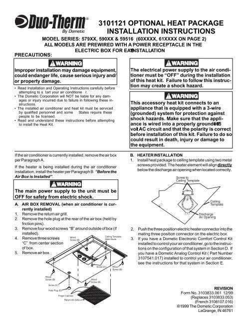
<strong>3101121</strong> OPTIONAL HEAT PACKAGEINSTALLATION INSTRUCTIONSMODEL SERIES: 579XX, 590XX & 59516 (60XXXX, 61XXXX ON PAGE 2)ALL MODELS ARE PREWIRED WITH A POWER RECEPTACLE IN THEELECTRIC BOX FOR EASYINSTALLATIONPRECAUTIONS:Improper installation may damage equipment,could endanger life, cause serious injury and/or property damage.• Read <strong>Installation</strong> and Operating <strong>Instructions</strong> carefully beforeattempting to s tart your air conditione r.• The Dometic Corporation will NOT be liable for any damagesor injury incurred due to failure in following these instructions.• The installed air conditioner and heat kit must be servicedby qualified personnel and some States require thesepeople to be licensed.• Read and understand these instructions before attemptingto install the <strong>Heat</strong> Kit.If the air conditioner is currently installed, remove the air boxper Paragraph A.If the heater is being installed during the air conditionerinstallation, install the heater per Paragraph B “Before . theAir Box is Installed”.The electrical power supply to the air conditionermust be “OFF” during the installationof this heat kit. Failure to follow this instructionmay create a shock hazard.This accessory heat kit connects to anappliance that is equipped with a 3-wire(grounded) system for protection againstshock hazards. Make sure that the applianceis wired into a properly grounded 115volt AC circuit and that the polarity is correctbefore installation of this kit. Failure to do socould result in death, injury or damage tothe equipment.B. HEATER INSTALLATION1. Install heat package to ceiling template using two metalscrews provided. The heater element will align directlybelow the discharge air opening when located correctly.The main power supply to the unit must beOFF for safety from electric shock.A. AIR BOX REMOVAL (when air conditioner is currentlyinstalled)1. Remove the return air grill.2. Remove the hole plug at the rear of the air box (held byfriction pins).3. Remove four wood screws “B” around outside of box (ifinstalled).4. Remove three screws“C” from center sectionof box.5. Remove air box.2. Push the three position electric heater connector into themating three position connector on the electric box.3. If you have a Dometic Electronic Comfort Control Kitinstalled to control your air conditioner, go to the instructionson the configuration of that system in Section D. Ifyou have a Dometic Analog Control Kit ( Part Number3107541.017) installed to control your air conditioner,see the instructions for that system in Section E.1REVISIONForm No. 3103833.061 12/99(Replaces 3103833.053)(French 3108107.016)®1999 The Dometic CorporationLaGrange, IN 46761
B. HEATER INSTALLATION1. Install heat package to ceiling template using two sheetmetal screws provided. The heater element will aligndirectly below the discharge air opening when locatedcorrectly.2. Push the heater electric connector into the back of themating connector on the electric box.a) Electronic Control: The cord routes over the ceilingtemplate to the junction box (left side).b) Mechanical Control:The cord routes directly into the right side switch box.D. AIR BOX INSTALLATION1. Remove the knockout in the air box wall. The insulation ispre-cut. (DO NOT remove any. It is necessary for a seal).2. Slide the air box into place (over the switch knobs if you havea mechanical control unit and then . . .) over the heater andguards.3. Secure the four screws through the air box legs into theceiling template (refer to the air conditioner <strong>Installation</strong><strong>Instructions</strong>).4. a) Electronic Controls: Reconnect the cables.b) Mechanical Controls: Reinstall the knobs.5. Snap the grills into place.6. TURN ON THE POWER and check operation per the airconditioner <strong>Installation</strong> and Operating <strong>Instructions</strong>.C. GUARD INSTALLATIONE. COMFORT CONTROL CENTER CONFIGURATION FORELECTRIC HEAT KITThe guard must be installed to prevent shockhazard to the user.1. Remove the screw at the back center of the ceilingtemplate, holding the return air duct.2. Install the guard 1/2” from the ceiling template left channelwith the same screw (through the grill as shown).Ensure all 115 Volt AC and 12 Volt DC poweris shut off.1. Locate Electronic Control Box.2. Remove access cover to expose dip switches.NOTE: The Electronic Control Box is factory shipped withdip switches in the “OFF” position.3. Place dip switch #1 <strong>Heat</strong> Strip to “ON” position.4. Replace access cover.5. Turn on electrical power to the air conditioner.3. If you have a Dometic Electronic Comfort Control Kitinstalled to control your air conditioner, go to the instructionson the configuration of that system in Section E. Ifyou have a Dometic Analog Control Kit (Part Number3107541.017) installed to control your air conditioner, seethe instructions for that system in Section F.3
6. SYSTEM CHECKOUT AND CONFIGURATIONNow that the system is installed, it is necessary to resetthe Comfort Control Center and check out the system.Refer to the Operating Manual for a description of the airconditioner operation.a. RESET COMFORT CONTROL CENTER:1. Turn control on to insure annunciator data and light arepresent. If data and light are present, continue withnext step.2. Press mode switch to activate annunciator light.3. Simultaneously press the bottom two buttons (Temperatureup and down) and hold.4. While holding these buttons down, press the modebutton once and release.5. Release the two buttons previously held down6. Depress the mode button once again.7. At this time the light should extinguish and the modeshould register “OFF”. If not, repeat steps 2 through6.b. SYSTEM CHECKOUT: Verify that all features of theinstalled system work. Check fan speeds, cooling mode,heat pump mode, furnace (if connected) and heat strip.If the features do not work, check all wiring and confirmthat the correct options have been selected on theElectronic Control Box. (See Comfort Control CenterOperating <strong>Instructions</strong>).c. Return to Step C for 579XX, 590XX and 59516 instructions.For Models 60XXXX and 61XXXX, refer to Step DAir Box <strong>Installation</strong>.F. ANALOG CONTROL HEAT STRIP INSTALLATIONEnsure all 115 Volt AC and 12 Volt DCpower is shut off.1. Locate the 3107541.017 Analog Control Box.2. Route the heater three position connector to its matchingoutlet on the Analog Control Box.Note: The electric heat kit will not be accepted for use withthe 3107541.009 cooling furnace or the 3107541.027 cooling,furnace and heat pump controls.3. Return to Step C for 579XX, 590XX and 59516 instructions.For Models 60XXXX and 61XXXX refer to Step D -Air Box <strong>Installation</strong>.4