service manual for 6700, 7000, 8000 & 9000 series air conditioners
service manual for 6700, 7000, 8000 & 9000 series air conditioners
service manual for 6700, 7000, 8000 & 9000 series air conditioners
- No tags were found...

Create successful ePaper yourself
Turn your PDF publications into a flip-book with our unique Google optimized e-Paper software.
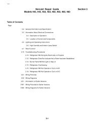
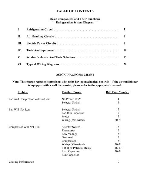
TABLE OF CONTENTSBasic Components and Their FunctionsRefrigeration System DiagramI. Refrigeration Circuit . . . . . . . . . . . . . . . . . . . . . . . . . . . . . . . . . . . . . . . . . . 5II. Air Handling Circuits . . . . . . . . . . . . . . . . . . . . . . . . . . . . . . . . . . . . . . . . . 6III. Electric Power Circuits . . . . . . . . . . . . . . . . . . . . . . . . . . . . . . . . . . . . . . . . 6IV. Tools And Equipment . . . . . . . . . . . . . . . . . . . . . . . . . . . . . . . . . . . . . . . . . 10V. Service Problems And Their Solutions . . . . . . . . . . . . . . . . . . . . . . . . . . . . 13VI. Typical Wiring Diagrams . . . . . . . . . . . . . . . . . . . . . . . . . . . . . . . . . . . . . . 20QUICK DIAGNOSIS CHARTNote: This charge represents problems with units having mechanical controls - if the <strong>air</strong> conditioneris equipped with a wall thermostat, please refer to the appropriate <strong>manual</strong>.Problem Possible Causes Ref. Page NumberFan And Compressor Will Not Run No Power 115V 14Selector Switch 14Fan Will Not Run Selector Switch 17Fan Run Capacitor 17Motor 17Wiring (Mis-wired) 20-21Compressor Will Not Run Selector Switch 15Thermostat 15Low Voltage 15Overload 15Compressor 15Wiring (Mis-wired) 20-21PTCR or Potential Relay 16-17Start Capacitor 20-21Run CapacitorCooling Per<strong>for</strong>mance 19