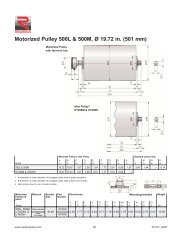
Motorized Pulley 220M & 220H, Ã 8.50 in. (216 mm)
Motorized Pulley 220M & 220H, Ã 8.50 in. (216 mm)
Motorized Pulley 220M & 220H, Ã 8.50 in. (216 mm)

You also want an ePaper? Increase the reach of your titles
YUMPU automatically turns print PDFs into web optimized ePapers that Google loves.
Rulmeca <strong>Motorized</strong> <strong>Pulley</strong>s: a new name with deep rootsThe Rulmeca <strong>Motorized</strong> <strong>Pulley</strong>s presented<strong>in</strong> this catalogue have a long historyto tell. It goes back to the 1950’s, whenthe product was developed <strong>in</strong> Germanyand Denmark.Eventually, through a merg<strong>in</strong>g processthe German Förder und AntriebstechnikAschersleben GmbH and the DanishJohn Kirkegaard Mask<strong>in</strong>fabrik A/Sbecame partners <strong>in</strong> the Interroll Group.From the early 1990’s the manufactur<strong>in</strong>gof all Interroll’s BULK <strong>Motorized</strong> <strong>Pulley</strong>swere centralized <strong>in</strong> Aschersleben, Germany.In July 2003 Rulli Rulmeca S.p.A. purchasedthe production facility <strong>in</strong> Aschersleben,Germany, where <strong>Motorized</strong> <strong>Pulley</strong>shave been developed and producedfor almost half a century, along with theentire BULK Bus<strong>in</strong>ess Unit.Today this plant, renamed RulmecaFAA GmbH, will cont<strong>in</strong>ue the JOKItradition for quality and reliability underthe Rulmeca brand.Thanks to this long history Rulmeca is avery experienced manufacturer of BULK<strong>Motorized</strong> <strong>Pulley</strong>s, offer<strong>in</strong>g the world’slargest product range.www.rulmecacorp.comwww.precismeca.ab.cawww.rulmecacorp.com 2TC101: 03/07
Features and Benefits of Rulmeca <strong>Motorized</strong> <strong>Pulley</strong>sPurpose-built designThe Rulmeca <strong>Motorized</strong> <strong>Pulley</strong> has beenspecifically designed for belt conveyors.Hermetically SealedThe motor, gearbox and bear<strong>in</strong>gs arehermetically sealed <strong>in</strong>side a steel shell.Therefore they are unlikely to fail due toharmful environmental conditions suchas water, dust, grit, chemicals, grease,oil, etc.Space sav<strong>in</strong>g designBecause the drive unit and the bear<strong>in</strong>gsare mounted <strong>in</strong>side the <strong>Motorized</strong> <strong>Pulley</strong>shell, it requires much less room than anexposed drive. No need for costly extraslike cha<strong>in</strong>s, v-belts, coupl<strong>in</strong>gs, bear<strong>in</strong>gs,support structure and special guard<strong>in</strong>g.SafetyThe Rulmeca <strong>Motorized</strong> <strong>Pulley</strong> is one ofthe safest drives available because themotor is completely enclosed and theexternal shafts are always stationary.The only mov<strong>in</strong>g external parts are the<strong>Motorized</strong> <strong>Pulley</strong> shell and bear<strong>in</strong>g hous<strong>in</strong>gs.Low purchas<strong>in</strong>g and <strong>in</strong>stallation costThe Rulmeca <strong>Motorized</strong> <strong>Pulley</strong> is quiteoften less expensive than exposeddrives because it has fewer parts. Thereforeless conveyor design time and partspurchas<strong>in</strong>g costs. It is also much quickerand easier to <strong>in</strong>stall - certa<strong>in</strong>ly less thana quarter of the time taken to fit anexposed system.Low ma<strong>in</strong>tenance costThe end user also benefits from the Rulmeca<strong>Motorized</strong> <strong>Pulley</strong>, because itrequires no ma<strong>in</strong>tenance other than thereco<strong>mm</strong>ended oil change every 10,000operat<strong>in</strong>g hours and oil seal changeevery 30,000 operat<strong>in</strong>g hours. In otherwords, almost 5 years between oilchanges based on an 8-hour/day work<strong>in</strong>gweek. Synthetic oil can be specifiedto extend the oil service life up to 30,000operat<strong>in</strong>g hours.EfficiencyThe Rulmeca <strong>Motorized</strong> <strong>Pulley</strong> usuallyhas a much higher efficiency from electricalmotor to shell (<strong>Pulley</strong> face) thanexposed drives, because it has fewerfrictional losses. Therefore, efficienciesof up to 97% can be achieved.Cleanl<strong>in</strong>essBecause the Rulmeca <strong>Motorized</strong> <strong>Pulley</strong>is hermetically sealed it cannot contam<strong>in</strong>ateany convey<strong>in</strong>g materials such asfood, electrical components, plastics andother materials that must be kept perfectlyclean dur<strong>in</strong>g handl<strong>in</strong>g.Aesthetic appearanceIf <strong>in</strong>stalled correctly the Rulmeca <strong>Motorized</strong><strong>Pulley</strong> always looks good. Due to itscompact size and smooth l<strong>in</strong>es, the<strong>Motorized</strong> <strong>Pulley</strong> is out of sight, because itis hidden with<strong>in</strong> the conveyor frame.Thermal protectionAll three phase Rulmeca <strong>Motorized</strong> <strong>Pulley</strong>sare protected by our thermal protectionswitches. These heat-sensitiveswitches are built <strong>in</strong>to the motor w<strong>in</strong>d<strong>in</strong>gsto protect the motor from overheat<strong>in</strong>g.The thermal protectors must be connectedto a normally closed control circuit<strong>in</strong> order to protect the motor.Weight sav<strong>in</strong>g and distributionThe Rulmeca <strong>Motorized</strong> <strong>Pulley</strong> is oftenlighter than exposed drives. It is possibleto reduce the weight and cost of theconveyor structure, because the conveyordrive weight is evenly distributed with<strong>in</strong>the conveyor frame.Variable frequency driveAll Rulmeca <strong>Motorized</strong> <strong>Pulley</strong>s with 3phase motors are easily controlled byvariable frequency drives work<strong>in</strong>g <strong>in</strong> the12 Hz to 66 Hz frequency range. SeeTechnical Precautions <strong>in</strong> the catalogue.Fewer partsA Rulmeca <strong>Motorized</strong> <strong>Pulley</strong> consists ofthe <strong>Motorized</strong> <strong>Pulley</strong> and two fix<strong>in</strong>gbrackets! Exposed drives can require upto eight or more separate components,most of which have to be purchasedfrom different suppliers or custom manufactured.Low noiseThanks to the totally sealed enclosureand high quality gears the Rulmeca<strong>Motorized</strong> <strong>Pulley</strong> runs almost at a whisper– a very important fact <strong>in</strong> today’smodern factory environments.The Rulmeca <strong>Motorized</strong> <strong>Pulley</strong> – theideal drive unit for conveyors “Fit itand forget it!”www.rulmecacorp.com 3TC101: 03/07
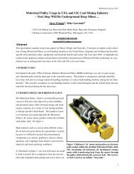
<strong>Motorized</strong> <strong>Pulley</strong>sDual Drive ConceptBucket Wheel Reclaimer for taconite pelletsLocated <strong>in</strong> “center drive position” beneath a 4,000 TPH bucket wheelreclaimer tail conveyor at Lake Superior taconite ship load<strong>in</strong>g facility, twomodel 800H 120 HP <strong>Motorized</strong> <strong>Pulley</strong>s drive discharge belt at 768 FPM.S<strong>in</strong>ce the 2004 reclaimer upgrade, each <strong>Motorized</strong> <strong>Pulley</strong> is powered by460V/3ph/60 Hz directly by the on-board diesel electric generator. Motorsynchronization was not necessary on either this reclaimer or its two sistermach<strong>in</strong>es at the term<strong>in</strong>al.Technical Precaution: Always mount motorized pulley with “UP” directionoriented accord<strong>in</strong>g to <strong>in</strong>stallation <strong>in</strong>structions.Revers<strong>in</strong>g Shuttle Conveyor for crushed graniteOne of two 31.5” diameter 50 HP <strong>Motorized</strong> <strong>Pulley</strong>s, one on north end andone on south end, driv<strong>in</strong>g revers<strong>in</strong>g shuttle conveyor at Lafarge’s Mountsorrelgranite quarry s<strong>in</strong>ce 1998. Photo shows stone discharg<strong>in</strong>g from 600FPM belt at 2,500 TPH. Chang<strong>in</strong>g from a “s<strong>in</strong>gle drive” to a “dual drive”arrangement can reduce slack-side belt tension (T 2) to 20%. This willreduce maximum belt tension (T 1) and can significantly extend conveyor beltlife because it provides 360 degrees of belt wrap around pulleys (180degrees per <strong>Motorized</strong> <strong>Pulley</strong>), without the use of “dirty side” snub pulleys.Technical Precaution: When us<strong>in</strong>g <strong>Motorized</strong> <strong>Pulley</strong>s <strong>in</strong> revers<strong>in</strong>g application,always br<strong>in</strong>g conveyor to complete stop before start<strong>in</strong>g belt <strong>in</strong> oppositedirection (see page 84-85.)Suspended Construction Conveyor for wet concreteOne of four 150 foot long “dual drive” conveyors suspended from constructioncranes to pour wet concrete dur<strong>in</strong>g Sesam River Dam construction <strong>in</strong>Southeast Asia. Dur<strong>in</strong>g the five year project each conveyor was driven atthe head and tail by a model 800H 50 HP Rulmeca <strong>Motorized</strong> <strong>Pulley</strong>.Overland Conveyor for graniteOne of two 150 HP Rulmeca <strong>Motorized</strong> <strong>Pulley</strong>s on two mile long overlandconveyor at Lafarge’s Mountsorrel Quarry <strong>in</strong> “center drive position.” The two<strong>Motorized</strong> <strong>Pulley</strong>s are driven by synchronized ABB variable frequencydrives (VFDs), transferr<strong>in</strong>g granite on the 48” wide belt at various rates upto 2,000 TPH. The VFDs: (1.) provide a “soft start” feature, (2.) enable thetwo drives to “talk” and keep rotor speeds synchronized, and (3.) conservepower by l<strong>in</strong>k<strong>in</strong>g to load sensors and optimiz<strong>in</strong>g belt speed accord<strong>in</strong>g tomeasured conveyor throughput.Technical Precaution: When us<strong>in</strong>g a VFD always restrict frequencies tobetween 12 Hz to 66 Hz and <strong>in</strong>stall a filter on the VFD output if it is locatedmore than 30 feet from the <strong>Motorized</strong> <strong>Pulley</strong> (see page 86.)www.rulmecacorp.com 6TC101: 03/07
<strong>Motorized</strong> <strong>Pulley</strong> 138E, Ø 5.45 <strong>in</strong>. (138 <strong>mm</strong>)<strong>Motorized</strong> <strong>Pulley</strong> with Term<strong>in</strong>al box<strong>Motorized</strong> <strong>Pulley</strong>with cablestraight connectorElbow connector(not for TS7N)Idler <strong>Pulley</strong> 3 TS7N version<strong>Motorized</strong> <strong>Pulley</strong> or idler <strong>Pulley</strong> (UT) Compact term<strong>in</strong>al Straight Elbowbox connector connectorA B C D E F G H K W L M N N1 U V R S TModel <strong>in</strong> <strong>in</strong> <strong>in</strong> <strong>in</strong> <strong>in</strong> <strong>in</strong> <strong>in</strong> <strong>in</strong> <strong>in</strong> <strong>in</strong> <strong>in</strong> <strong>in</strong> <strong>in</strong> <strong>in</strong> <strong>in</strong> <strong>in</strong> <strong>in</strong> <strong>in</strong> <strong>in</strong>138E 5.45 5.39 0.93 1.18 2.13 0.79 0.20 0.65 0.93 – 1.61 0.95 3.74 0.55 0.14 0.77 0.79 1.89 0.47UT138E 5.45 5.45 0.93 1.18 2.13 0.79 0.53 0.65 – 1.421 A dimension is outer diameter of unlagged pulley shell at pulley centerl<strong>in</strong>e.2 B dimension is outer diameter of unlagged pulley shell at each end of shell.3 Idler pulley shown is non-crowned TS7N version with regreasable seals.Mount<strong>in</strong>g brackets<strong>Motorized</strong><strong>Pulley</strong>sMaterialBracketSizePartNumberDimensionsWeightModel138ECast ironpa<strong>in</strong>tedCast ironNi platedSta<strong>in</strong>lesssteelKL30S2YAKLS2YAKMS3KL33A<strong>in</strong>D<strong>in</strong>F<strong>in</strong>I<strong>in</strong>K<strong>in</strong>S<strong>in</strong>T<strong>in</strong>7.09 1.18 0.79 3.39 2.24 0.43 0.67 0.47 0.95 4.33 1.75 2.83 1.54V<strong>in</strong>W1<strong>in</strong>X<strong>in</strong>Z<strong>in</strong>Z1<strong>in</strong>lbswww.rulmecacorp.com 10TC101: 03/07
<strong>Motorized</strong> <strong>Pulley</strong> 138E, Ø 5.45 <strong>in</strong>. (138 <strong>mm</strong>)60 HzPowerHPMotorNo.ofPoles0.13 120.25 80.33 60.50 40.75 21.0No.GearStagesModel3 138ENom<strong>in</strong>al beltspeed 1 atFull Load60 Hzfpm1012142 138E 24303 138E1824302 138E 383 138E2 138E3 138E2 138E3 138E2 138E4 3 138E2 2 138E482430384860763848607696120150486076961201501922403007696120150192240300Actual beltspeed 1 atFull Load60 Hzfpm1014162428202429445125313855658238475885981231505564749311316619624429688104129157207258314BeltPull 2lbs39731826317815238430925417214740432526518215512441233127318515812610441636331024920513911995Max.RadialLoad 3T1 + T2lbsM<strong>in</strong>.RL<strong>in</strong>RL Dimension <strong>in</strong>ches (RL max = 70.87”)Weight <strong>in</strong> lbs 511.81 12.60 13.78 15.75 17.72 19.69 21.65 23.62 25.591,066 11.81 32 33 34 37 40 42 44 46 4978357304244201 12.60 - 34 37 41 43 45 47 49 53152122100longerthan25.59SeeFootnote4TypeofBracketKL30S2YAKLIdler <strong>Pulley</strong> Model UT138E 1,066 11.81 15 16 18 21 23 25 27 29 32SeeFootnote4KL30S2YAKL1 Use “nom<strong>in</strong>al belt speed” to specify pulley. “Actual belt speed” is presented (for pulley lagged with 1/8” thick rubber) to assist with process design calculations.See Technical Precautions page 77. Note that “actual belt speed” decreases when lagg<strong>in</strong>g is not used due to decreased pulley diameter.2 Belt pull value allows for gearbox loss.3 <strong>Pulley</strong> must not be subjected to radial load exceed<strong>in</strong>g “Maximum radial load” def<strong>in</strong>ed above. See “Belt Tension” section <strong>in</strong> Technical Precautions, page 78.4 Additional <strong>Motorized</strong> <strong>Pulley</strong> and Idler <strong>Pulley</strong> weight, specified per Roller Length:25.59”< RL < 39.37” Wt = 1.3 lbs/<strong>in</strong>ch39.37”< RL < 59.06” Wt = 1.5 lbs/<strong>in</strong>ch59.06”< RL < 70.87” Wt = 2.0 lbs/<strong>in</strong>ch5 All weights shown above are for pulleys with 1/8” thick rubber lagg<strong>in</strong>g. To calculate unlagged pulley weight subtract 0.1 lbs/<strong>in</strong> of Roller Length from above.www.rulmecacorp.com 11TC101: 03/07
<strong>Motorized</strong> <strong>Pulley</strong> 138E, Ø 5.45 <strong>in</strong>. (138 <strong>mm</strong>)Spare parts list and sectional draw<strong>in</strong>gsPos. Description Pos. Description Pos. Description1 Front shaft3 Rear flange5 Bear<strong>in</strong>g hous<strong>in</strong>g complete withgeared rim7 Bear<strong>in</strong>g hous<strong>in</strong>g complete8 Gearbox10 Term<strong>in</strong>al box – bottom part11 Term<strong>in</strong>al box cover12 Shell16 Rear shaft19 Input wheel20 Output p<strong>in</strong>ion22 Geared rim23 Intermediate p<strong>in</strong>ion shaft24 Intermediate wheel31 Labyr<strong>in</strong>th seal cover53 Nipple (term<strong>in</strong>al box53.1 Cable seal nipple (cable option)55 Spacer bush<strong>in</strong>g56 Spacer bush<strong>in</strong>g63 Ball bear<strong>in</strong>g64 Needle bear<strong>in</strong>g65–70 Ball bear<strong>in</strong>g71 Inner race74 Lock<strong>in</strong>g r<strong>in</strong>g84 Lock<strong>in</strong>g r<strong>in</strong>g86 Lock<strong>in</strong>g r<strong>in</strong>g93 Elbow or straight connector102 Screw103 Screw110 Screw111 Screw113 Screw114 Socket set screw115 Oil plug with magnet126 Key127 Key131 Key132 Key136 O-r<strong>in</strong>g/Rubber seal138 Rubber seal139 Grease nipple140 Deflection seal142 Double lip seal143 O-r<strong>in</strong>g2-stage gearboxwww.rulmecacorp.com 12TC101: 03/07
<strong>Motorized</strong> <strong>Pulley</strong> 138E, Ø 5.45 <strong>in</strong>. (138 <strong>mm</strong>)Spare parts list and sectional draw<strong>in</strong>gsPos. Description Pos. Description Pos. Description145 Distance washer146 Washer148 Washer150 Electromagnetic brake150.1 Friction disc156 Rectifier (not shown)160 Oil plug161 O-r<strong>in</strong>g163 O-r<strong>in</strong>g167 Screw200 Rubber seal204 Rotor complete with p<strong>in</strong>ion208 Sta<strong>in</strong>less steel cover – gearend210 Fix<strong>in</strong>g guard223 Cable226 Stator complete240 Distance r<strong>in</strong>gTS7N with cable connectionElbow connectorTS7N with cable connection 3-stage gearbox Electromagnetic brakewww.rulmecacorp.com 13TC101: 03/07
<strong>Motorized</strong> <strong>Pulley</strong> 165E, Ø 6.49 <strong>in</strong>. (165 <strong>mm</strong>)<strong>Motorized</strong> <strong>Pulley</strong> 165E, withmach<strong>in</strong>ed helical gearbox, performswith a gearbox efficiency of 95% ofnom<strong>in</strong>al power, <strong>in</strong> a compact diameterof 6.49 <strong>in</strong>ches. With a m<strong>in</strong>imumroller length (RL) of 13.78” and powersrang<strong>in</strong>g from 0.15 to 3.0 HP, this<strong>Motorized</strong> <strong>Pulley</strong> is suitable for mostsmall diameter applications. These<strong>in</strong>clude:• Light agricultural conveyors• Light C & D debris conveyors• Mobile and portable conveyors<strong>Motorized</strong> <strong>Pulley</strong> 165E features astandard enclosure class of IP66/67and is also available <strong>in</strong> sta<strong>in</strong>lesssteel for wash down applications.STANDARD SPECIFICATIONof <strong>Motorized</strong> <strong>Pulley</strong>• Crowned mild steel 6.49” shell treatedwith anti-rust wax• Die cast alum<strong>in</strong>um bear<strong>in</strong>g hous<strong>in</strong>g• Mild steel shaft treated with anti-rustwax• Die cast lightweight alum<strong>in</strong>um gearboxhous<strong>in</strong>g• Seal<strong>in</strong>g system – degree of protectionIP66/67 (EN60034-5.) See page 88.• Compact die cast alum<strong>in</strong>um term<strong>in</strong>albox with WAGO connectors• Voltage: All co<strong>mm</strong>on voltages available.Please specify.• Three phase <strong>in</strong>duction motor• One out of two oil plugs is fitted with amagnet to filter the oil.• Motor w<strong>in</strong>d<strong>in</strong>g <strong>in</strong>sulation class F• Dynamically balanced rotor• Oil change reco<strong>mm</strong>ended every10,000 operational hours• Maximum RL 70.87”• Non standard RL lengths available• S<strong>in</strong>gle phase is available <strong>in</strong> 0.50 and1.50 HP, supplied with a runn<strong>in</strong>g capacitor• To be used <strong>in</strong> the horizontal positiononly.STAINLESS STEELoptionsTS7N• Sta<strong>in</strong>less steel shell – AISI 304 range• Sta<strong>in</strong>less steel shafts – AISI 303 range• Sta<strong>in</strong>less steel covered alum<strong>in</strong>um bear<strong>in</strong>ghous<strong>in</strong>gs – AISI 304 range• Sta<strong>in</strong>less steel oil plugs with magnet –AISI 304 range• Compact sta<strong>in</strong>less steel term<strong>in</strong>al box –AISI 304 range• Alternatively, straight sta<strong>in</strong>less steelconnector – AISI 303 range with powercord.• Regreasable sta<strong>in</strong>less steel seals –AISI 303 range• Degree of protection IP66/67 (EN60034-5.) See page 88.• FDA & USDA food grade grease• Option: FDA & USDA food grade recognizedoil.• Special mount<strong>in</strong>g brackets are available.Please note:• Noise-sensitive Areas: High speed 2-pole motors can cause higher noiselevels and are not reco<strong>mm</strong>ended fornoise-sensitive areas• Technical Precautions for Design,Installation, and Ma<strong>in</strong>tenance: pages76-86• Environmental Considerations: page72• Optional Extras: pg 15 and back cover• Electrical Connection Diagrams:pages 94-96.www.rulmecacorp.com 14TC101: 03/07
OPTIONAL EXTRAS<strong>Motorized</strong> <strong>Pulley</strong> 165ESpecificationAvailabilityTotal sta<strong>in</strong>less steel option AISI 304 range TS7N with regreasable labyr<strong>in</strong>th seals xFood grade oil & grease - FDA & USDA recognizedxDust explosion proof <strong>Motorized</strong> <strong>Pulley</strong>s - ATEX 95 - Zone 22 - for applicationshandl<strong>in</strong>g dusty gra<strong>in</strong> etc. Accord<strong>in</strong>g to European Directive 94/9/EC.xTotal acid resistant sta<strong>in</strong>less steel option - AISI 316xBlack rubber lagg<strong>in</strong>g - Standard specifications (See page 80.)1/8” smooth lagg<strong>in</strong>g - Hardness 60 ±5 Shore A oWhite smooth rubber lagg<strong>in</strong>g (FDA). Oil, fat & grease resistantoSpecial lagg<strong>in</strong>g (e.g. hot vulcanized)oElectromagnetic brake M<strong>in</strong>. RL <strong>in</strong>creases by 1.97” xMechanical backstop M<strong>in</strong>. RL does not <strong>in</strong>crease with backstop option xModified for vertical mount<strong>in</strong>goModified for mount<strong>in</strong>g between 5° and 90° (e.g. for magnetic separators)Insulation class F with standard oil: (Allowable ambient temperature: -13°F/+104°F)Insulation class H with synthetic oil: (Allowable ambient temperature: -13°F/+120°F)Special motors for applications with no belt contactLow noise drives for noise sensitive areasParallel shellThermal protectorStd.IP66/67 Compact unpa<strong>in</strong>ted alum<strong>in</strong>um term<strong>in</strong>al boxStd.IP66/67 Compact sta<strong>in</strong>less steel term<strong>in</strong>al box- AISI 304 or 316 rangexStraight or elbow connector with standard power cordxStraight connector with screened power cord (See page 86 for VFD precautions) xStraight connector with standard power cord (Sta<strong>in</strong>less steel <strong>in</strong> AISI 304 range) xVoltage: s<strong>in</strong>gle voltage (460) stator (Y w<strong>in</strong>d<strong>in</strong>g) wired for 460v/3ph/60 Hz at term<strong>in</strong>al boxStd.s<strong>in</strong>gle voltage (230) stator (YY w<strong>in</strong>d<strong>in</strong>g) wired for 230v/3ph/60 Hz at term<strong>in</strong>al boxx2 speed motors xSpecial voltage motorsxS<strong>in</strong>gle phase motorsCSA approved motorsoStd.xoxxoxx = Optional extra’so = An option with certa<strong>in</strong> limitations. Please refer to Technical precautions pages 76-86!Std. = Fitted as standardwww.rulmecacorp.com 15TC101: 03/07
<strong>Motorized</strong> <strong>Pulley</strong> 165E, Ø 6.49 <strong>in</strong>. (165 <strong>mm</strong>)<strong>Motorized</strong> <strong>Pulley</strong> with Term<strong>in</strong>al Box<strong>Motorized</strong> <strong>Pulley</strong>with cablestraight connectorElbow connector(not for TS7N)Idler <strong>Pulley</strong> 3 TS7N version<strong>Motorized</strong> <strong>Pulley</strong> or idler <strong>Pulley</strong> (UT) Compact term<strong>in</strong>al Straight Elbowbox connector connectorA B C D E F G H K W L M N N1 U V R S TModel <strong>in</strong> <strong>in</strong> <strong>in</strong> <strong>in</strong> <strong>in</strong> <strong>in</strong> <strong>in</strong> <strong>in</strong> <strong>in</strong> <strong>in</strong> <strong>in</strong> <strong>in</strong> <strong>in</strong> <strong>in</strong> <strong>in</strong> <strong>in</strong> <strong>in</strong> <strong>in</strong> <strong>in</strong>165E 6.49 6.44 1.71 1.57 3.15 1.18 0.39 0.85 1.63 – 1.61 0.95 3.74 0.55 0.16 1.06 0.79 1.89 0.47UT165E 6.49 6.49 1.71 1.57 2.95 1.18 0.65 0.85 – 1.811 A dimension is outer diameter of unlagged pulley shell at pulley centerl<strong>in</strong>e.2 B dimension is outer diameter of unlagged pulley shell at each end of shell.3 Idler pulley shown is non-crowned TS7N version with regreasable seals.Mount<strong>in</strong>g brackets<strong>Motorized</strong><strong>Pulley</strong>sMaterialBracketSizePartNumberDimensionsWeightModelSteel pa<strong>in</strong>ted6YA0KA<strong>in</strong>D<strong>in</strong>F<strong>in</strong>I<strong>in</strong>K<strong>in</strong>S<strong>in</strong>T<strong>in</strong>V<strong>in</strong>W1<strong>in</strong>X<strong>in</strong>Z<strong>in</strong>Z1<strong>in</strong>lbs165ESteelNi platedSta<strong>in</strong>lesssteelKL41-HD6YA0W6YA0U7.48 1.57 1.18 3.31 2.44 0.55 0.79 0.87 1.57 4.33 1.97 3.27 4.63www.rulmecacorp.com 16TC101: 03/07
<strong>Motorized</strong> <strong>Pulley</strong> 165E, Ø 6.49 <strong>in</strong>. (165 <strong>mm</strong>)60 HzPowerHPMotorNo.ofPolesNo.GearStagesModel0.15 12 3 165E0.5041.00 41.502.00 23.00 2Nom<strong>in</strong>al beltspeed 1 atFull Load60 Hzfpm121418246 3 165E 243038483 165E 6076962 165E3 165E120150192Actual beltspeed 1 atFull Load60 Hzfpm1416202625303748597798123152199BeltPull 2lbsMax.RadialLoad 3T1 + T2lbs240 251 62 195538 38 81048 48 66460 59 53776 77 40996 98 325 2097120 123 2562 165E150 152 207192 199 158240 251 125 19554 3 165E 60 66 73076 81 56996 99 467 20973 165E 120 123 378150 161 288192 203 2282240 257 180 1955300 318 1452 165E3844806003 165E1201501922403002 165E 3844806007683 165E1201501923 165E 2403003842 165E 48060076841652564612316120325731841652565178713<strong>216</strong>1192250302417527648783M<strong>in</strong>.RL<strong>in</strong>15.75RL Dimension <strong>in</strong>ches (RL max = 70.87”)Weight <strong>in</strong> lbs 515.75 17.72 19.69 21.65 23.62 25.59 27.56 29.53 31.5035128866 69 72 76 78 80 83 87 9023317762451268 71 75 78 80 83 86 89 92414 2,09732826520<strong>216</strong>0 64 67 70 73 76 78 81 84 8812610278111887451539331124619815112010588717588466378314227180146121156220971955156220971955156270 74 77 80 82 84 88 91 9475 78 81 84 87 89 92 95 9977 80 83 87 89 91 94 98 10117.72 - 84 87 91 93 95 98 102 105longerthan31.50SeeFootnote4TypeofBracketKL41-HD6YA0KIdler <strong>Pulley</strong> Model UT165E 2,097 15.75 33 35 39 43 45 47 50 54 58SeeFootnote4KL41-HD6YA0K1 Use “nom<strong>in</strong>al belt speed” to specify pulley. “Actual belt speed” is presented (for pulley lagged with 1/8” thick rubber) to assist with process design calculations.See Technical Precautions page 77. Note that “actual belt speed” decreases when lagg<strong>in</strong>g is not used due to decreased pulley diameter.2 Belt pull value allows for gearbox loss.3 <strong>Pulley</strong> must not be subjected to radial load exceed<strong>in</strong>g “Maximum radial load” def<strong>in</strong>ed above. See “Belt Tension” section <strong>in</strong> Technical Precautions, page 78.4 Additional <strong>Motorized</strong> <strong>Pulley</strong> and Idler <strong>Pulley</strong> weight, specified per <strong>in</strong>ch of Roller Length:31.50”< RL < 45.28” Wt = 1.5 lbs/<strong>in</strong>45.28”< RL < 64.96” Wt = 2.1 lbs/<strong>in</strong>64.96”< RL < 70.87” Wt = 2.9 lbs/<strong>in</strong>5 All weights shown above are for pulleys with 1/8” thick rubber lagg<strong>in</strong>g. To calculate unlagged pulley weight subtract 0.1 lbs/<strong>in</strong> of Roller Length from above.www.rulmecacorp.com 17TC101: 03/07
<strong>Motorized</strong> <strong>Pulley</strong> 165E, Ø 6.49 <strong>in</strong>. (165 <strong>mm</strong>)Spare parts list and sectional draw<strong>in</strong>gsPos. Description Pos. Description Pos. Description1 Front shaft3 Rear flange5 Bear<strong>in</strong>g hous<strong>in</strong>g complete withgeared rim7 Bear<strong>in</strong>g hous<strong>in</strong>g complete8 Gearbox10 Term<strong>in</strong>al box – bottom part11 Term<strong>in</strong>al box cover12 Shell16 Rear shaft19 Input wheel20 Output p<strong>in</strong>ion22 Geared rim23 Intermediate p<strong>in</strong>ion shaft24 Intermediate wheel31 Labyr<strong>in</strong>th seal cover53 Cable seal nipple (cable option)53.1 Nipple (term<strong>in</strong>al box)55 Spacer bush<strong>in</strong>g56 Spacer bush<strong>in</strong>g63 Ball bear<strong>in</strong>g64 Needle bear<strong>in</strong>g65–70 Ball bear<strong>in</strong>g71 Inner race73 Lock<strong>in</strong>g r<strong>in</strong>g74 Lock<strong>in</strong>g r<strong>in</strong>g74 Lock<strong>in</strong>g r<strong>in</strong>g81 Lock<strong>in</strong>g r<strong>in</strong>g84 Lock<strong>in</strong>g r<strong>in</strong>g85 Lock<strong>in</strong>g r<strong>in</strong>g86 Lock<strong>in</strong>g r<strong>in</strong>g93 Elbow or straight connector102 Screw103 Screw110 Screw111 Screw112 Socket set screw113 Screw114 Socket set screw115 Oil plug with magnet126 Key127 Key131 Key132 Key136 O-r<strong>in</strong>g/Rubber seal138 Rubber seal2-stage gearboxwww.rulmecacorp.com 18TC101: 03/07
<strong>Motorized</strong> <strong>Pulley</strong> 165E, Ø 6.49 <strong>in</strong>. (165 <strong>mm</strong>)Spare parts list and sectional draw<strong>in</strong>gsPos. Description Pos. Description Pos. Description139 Grease nipple140 Deflection seal141 Double lip seal142 Double lip seal143 O-r<strong>in</strong>g145 Distance washer146 Washer148 Washer150 Electromagnetic brake150.1 Friction disc156 Rectifier (not shown)160 Oil plug161 O-r<strong>in</strong>g163 O-r<strong>in</strong>g167 Screw200 Rubber seal204 Rotor complete with p<strong>in</strong>ion206 Insulated sleeve for wireprotection208 Sta<strong>in</strong>less steel cover – gearend209 Sta<strong>in</strong>less steel cover – oil plugend210 Fix<strong>in</strong>g guard223 Cable226 Stator complete240 Distance r<strong>in</strong>gTS7NElbow connectorTS7N with cable connection 3-stage gearbox Electromagnetic brakewww.rulmecacorp.com 19TC101: 03/07
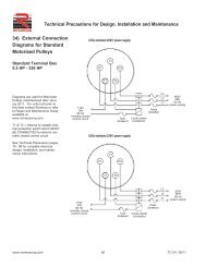
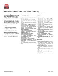
<strong>Motorized</strong> <strong>Pulley</strong> <strong>220M</strong> & <strong>220H</strong>, Ø <strong>8.50</strong> <strong>in</strong>. (<strong>216</strong> <strong>mm</strong>)Our <strong>8.50</strong>” diameter <strong>Motorized</strong> <strong>Pulley</strong>range offers two differentperformance levels for BULKapplications:- M for Medium duty- H for Heavy dutyIt is important to note the productdifferences and choose theappropriate pulley based onestimated belt tension (radial load.)See page 78. The actual radial loadmust be less than the maximumallowable radial load shown <strong>in</strong> thiscatalog.Be aware of <strong>in</strong>creased belttensions required to drive multi-plythick heavy belts and/or larger beltwidths.If the <strong>8.50</strong>” diameter model is notstrong enough to resist estimatedbelt tension, then select 12.64”diameter model.M for Medium dutyThe <strong>in</strong>ternal parts of <strong>220M</strong> aredesigned to match irregular work<strong>in</strong>gconditions <strong>in</strong> applications such asmobile crush<strong>in</strong>g & screen<strong>in</strong>g, cement& concrete plants, mobile conveyorsand open stone & gravel pits.H for Heavy dutyA re<strong>in</strong>forced 3-stage-gearboxprovides <strong>220H</strong> with the necessarystrength needed for low speeds andhigh torque. <strong>220H</strong> is popular <strong>in</strong> recycl<strong>in</strong>g(hand sorter conveyors),bunker discharge conveyors andwhere a comb<strong>in</strong>ation of slow speedand high torque is required.STANDARD SPECIFICATIONof <strong>Motorized</strong> <strong>Pulley</strong>• Crowned mild steel <strong>8.50</strong>” diameter steelshell treated with anti-rust wax• Powder coated cast iron bear<strong>in</strong>g hous<strong>in</strong>gs• Mild steel shafts treated with anti-rustwax• Shaft seal<strong>in</strong>g system - degree of protectionIP66/67 (EN60034-5.) Seepage 88.• Powder coated die cast alum<strong>in</strong>um term<strong>in</strong>albox• 3-phase <strong>in</strong>duction motors with thermalprotector• Voltage: All co<strong>mm</strong>on voltages available.Please specify.• Motor w<strong>in</strong>d<strong>in</strong>g <strong>in</strong>sulation Class F• Dynamically balanced rotor• One out of two oil plugs fitted with amagnet to filter the oil• Oil change reco<strong>mm</strong>ended every10,000 operational hours• M<strong>in</strong>imum RL. Please refer to pages23-24• Maximum RL – Please <strong>in</strong>quire• Non standard RL’s available• To be used <strong>in</strong> horizontal positions ± 5degree onlyPlease note:• Noise-sensitive Areas: High speed 2-pole motors can cause higher noiselevels and are not reco<strong>mm</strong>ended fornoise-sensitive areas• Technical Precautions for Design,Installation, and Ma<strong>in</strong>tenance: pages76-86• Environmental Considerations: page72• Optional Extras: pg 21 and back cover• Electrical Connection Diagrams:pages 94-96.STAINLESS STEELoptionsTS9N• Sta<strong>in</strong>less steel shell – AISI 304 range• Sta<strong>in</strong>less steel shafts – AISI 303/4range• Sta<strong>in</strong>less steel covered bear<strong>in</strong>g hous<strong>in</strong>gs– AISI 316 range• Sta<strong>in</strong>less steel oil plugs – AISI 304range – one out of two with magnet• Sta<strong>in</strong>less steel exterior bolts – AISI 304range• Regreasable labyr<strong>in</strong>th seals withgrease nipples <strong>in</strong> sta<strong>in</strong>less steel– AISI 304 range• Shaft seal<strong>in</strong>g system – degree of protectionIP66/67 (EN60034-5).TS10N• As TS9N, but without regreasablelabyr<strong>in</strong>th seals.SEMI-RUST-FREE optionsTS11N• As TS9N, but with crowned mild steelshell treated with anti-rust wax.TS12N• As TS10N, but with crowned mild steelshell treated with anti-rust wax.Other Sta<strong>in</strong>less Options:• FDA & USDA food grade recognizedoil and grease are not <strong>in</strong>cluded <strong>in</strong> TS9Nto TS12N, but available on request• Complete <strong>Motorized</strong> <strong>Pulley</strong>s <strong>in</strong> acidresistant sta<strong>in</strong>less steel – AISI 316range – available on request.• Special mount<strong>in</strong>g brackets are availableElectrical connection options:• Salt water resistant powder coatedalum<strong>in</strong>um term<strong>in</strong>al box with z<strong>in</strong>c platedexterior bolts• Sta<strong>in</strong>less steel term<strong>in</strong>al box – AISI 304range (max. 5.5 HP)• Straight sta<strong>in</strong>less steel connector withfly<strong>in</strong>g lead – AISI 304 range.Please specify required TS-numberwhen order<strong>in</strong>g Sta<strong>in</strong>less Steeloptions.www.rulmecacorp.com 20TC101: 03/07
OPTIONAL EXTRAS<strong>Motorized</strong> <strong>Pulley</strong> <strong>220M</strong> & <strong>220H</strong>SpecificationAvailabilityTotal sta<strong>in</strong>less steel option AISI 304 range TS9N with regreasable labyr<strong>in</strong>th seals xTotal sta<strong>in</strong>less steel option AISI 304 range TS10N with standard seals xSemi-rust free option TS11N with regreasable labyr<strong>in</strong>th seals xSemi-rust free option TS12N with standard seals xRegreasable labyr<strong>in</strong>th sealsxFood grade oil & grease - FDA & USDA recognizedxDust explosion proof <strong>Motorized</strong> <strong>Pulley</strong>s - ATEX 95 - Zone 22 - for applications handl<strong>in</strong>g of dusty gra<strong>in</strong> etc.Accord<strong>in</strong>g to European Directive 94/9/EC.xTotal acid resistant sta<strong>in</strong>less steel option - AISI 316xBlack rubber lagg<strong>in</strong>g - Standard specifications (See page 80.)1/4” smooth lagg<strong>in</strong>g - Hardness 60 ±5 Shore A o1/4” diamond lagg<strong>in</strong>g - Hardness 60 ±5 Shore A oWhite smooth rubber lagg<strong>in</strong>g (FDA). Oil, fat & grease resistantoSpecial lagg<strong>in</strong>g (e.g. hot vulcanized)oElectromagnetic brake M<strong>in</strong>. RL <strong>in</strong>creases by 3.94” xMechanical backstop M<strong>in</strong>. RL does not <strong>in</strong>crease with backstop option xModified for vertical mount<strong>in</strong>goModified for mount<strong>in</strong>g between 5° and 90° (e.g. for magnetic separators)oInsulation class F with standard oil: (Allowable ambient temperature -13°F/+104°F)Std.Insulation class H with synthetic oil: (Allowable ambient temperature -13°F/+120°F)xSpecial motors for applications with no belt contactoLow noise drives for noise sensitive areasxParallel shell (i.e. no crown)xThermal protectorStd.IP66/67 Yellow powder coated alum<strong>in</strong>um term<strong>in</strong>al boxStd.IP66/67 Gray powder coated alum<strong>in</strong>um term<strong>in</strong>al box (food grade approved)xIP66/67 Compact powder coated alum<strong>in</strong>um term<strong>in</strong>al box (food grade approved) < 5.5 HP only oIP66/67 Compact sta<strong>in</strong>less steel term<strong>in</strong>al box - AISI 304 or 316 range < 5.5 HP only oStraight or elbow connector with standard power cord < 5.5 HP only xStraight connector with screened power cord (See page 86 for VFD precautions.) < 5.5 HP only xStraight connector with power cord (Sta<strong>in</strong>less steel <strong>in</strong> AISI 304 range) < 5.5 HP only xVoltage: < 5.5 HP dual voltage (230/460) stator (YY/Y w<strong>in</strong>d<strong>in</strong>g) wired for 460v/3ph/60 Hz at term<strong>in</strong>al boxStd.< 5.5 HP dual voltage (230/460) stator (YY/Y w<strong>in</strong>d<strong>in</strong>g) wired for 230v/3ph/60 Hz at term<strong>in</strong>al box x7.5 HP s<strong>in</strong>gle voltage (460) stator (Y w<strong>in</strong>d<strong>in</strong>g) wired for 460v/3ph/60 Hz at term<strong>in</strong>al box Std7.5 HP s<strong>in</strong>gle voltage (230) stator (YY w<strong>in</strong>d<strong>in</strong>g) wired for 230v/3ph/60 Hz at term<strong>in</strong>al box x2 speed motors xSpecial voltage motorsxS<strong>in</strong>gle phase motorsoCSA approved motorsxx = Optional extraso = An option with certa<strong>in</strong> limitations. Please refer to Technical precautions pages 76-86Std. = Fitted as standardwww.rulmecacorp.com 21TC101: 03/07
<strong>Motorized</strong> <strong>Pulley</strong> <strong>220M</strong> & <strong>220H</strong>, Ø <strong>8.50</strong> <strong>in</strong>. (<strong>216</strong> <strong>mm</strong>)Compactterm<strong>in</strong>al box< 5.5 HPStandardterm<strong>in</strong>al box<strong>Motorized</strong> <strong>Pulley</strong> with term<strong>in</strong>al boxStraightconnectorElbowconnectorIdler <strong>Pulley</strong> 3 UT<strong>220M</strong> / UT<strong>220H</strong><strong>in</strong> TS9N/TS11N<strong>Motorized</strong> <strong>Pulley</strong> or Idler <strong>Pulley</strong> Standard term<strong>in</strong>al Compact term<strong>in</strong>al Straight Elbowbox box < 5.5 HP connector connectorG < 5.5 HP < 5.5 HPA B C D E F G TS9/11 H K W L M N O L M N N1 U V R S TModel <strong>in</strong> <strong>in</strong> <strong>in</strong> <strong>in</strong> <strong>in</strong> <strong>in</strong> <strong>in</strong> <strong>in</strong> <strong>in</strong> <strong>in</strong> <strong>in</strong> <strong>in</strong> <strong>in</strong> <strong>in</strong> <strong>in</strong> <strong>in</strong> <strong>in</strong> <strong>in</strong> <strong>in</strong> <strong>in</strong> <strong>in</strong> <strong>in</strong> <strong>in</strong> <strong>in</strong><strong>220M</strong> & <strong>220H</strong> <strong>8.50</strong> 8.44 1.71 1.57 3.94 1.18 0.61 0.77 0.85 1.63 – 3.43 1.06 4.21 4.13 1.61 0.95 3.74 0.55 0.16 1.06 0.79 1.89 0.47UT<strong>220M</strong> & UT<strong>220H</strong> <strong>8.50</strong> <strong>8.50</strong> 1.71 1.57 3.94 1.18 0.61 0.77 0.85 – 2.051 A dimension is outer diameter of unlagged pulley shell at pulley centerl<strong>in</strong>e.2 B dimension is outer diameter of unlagged pulley shell at each end of shell.3 Idler pulley shown is non-crowned TS9N/TS11N version with regreasable seals.<strong>Motorized</strong><strong>Pulley</strong>sModelMaterialBracketSizePartNumberDimensionsD<strong>in</strong>F<strong>in</strong>I<strong>in</strong>K<strong>in</strong>S<strong>in</strong>T<strong>in</strong>V<strong>in</strong>Mount<strong>in</strong>g bracketsW1<strong>in</strong>X<strong>in</strong>X1<strong>in</strong>Z<strong>in</strong>Z1<strong>in</strong>WeightlbsSteel pa<strong>in</strong>ted6YA0K<strong>220M</strong> &<strong>220H</strong>SteelNi platedKL41-HD6YA0W1.57 1.18 3.31 2.44 0.55 0.79 0.87 1.57 4.33 7.48 1.97 3.27 4.63Sta<strong>in</strong>less steel6YA0Uwww.rulmecacorp.com 22TC101: 03/07
<strong>Motorized</strong> <strong>Pulley</strong> <strong>220M</strong> & <strong>220H</strong>, Ø <strong>8.50</strong> <strong>in</strong>. (<strong>216</strong> <strong>mm</strong>)60 HzPowerHPMotorNo.ofPolesNo.GearStagesModelNom<strong>in</strong>al beltspeed 1 atFull Load60 Hzfpm3 <strong>220H</strong> 30384860760.50 8962 <strong>220M</strong> 1201501922403003 <strong>220H</strong> 30384860760.75 8962 <strong>220M</strong> 1201501922403003 <strong>220H</strong>24303848601 876962 <strong>220M</strong> 120150192240300303 <strong>220H</strong> 386482 <strong>220M</strong> 6076961.51201501924 2 <strong>220M</strong> 240300384480600Actual beltspeed 1 atFull Load60 Hzfpm344054698410112815920825031934405469841011281592082503192834405469841011281592082503193746547291108137168201256319415501637BeltPull 2lbs458383287227185155122977562496855774303372772311811461129373113792877458346037631424719815212699125110218526415064273372762301801451119373Max.RadialLoad 3T1 + T2lbsM<strong>in</strong>.RL<strong>in</strong>RL Dimension <strong>in</strong>ches (RL>78.74” available on request)Weight <strong>in</strong> lbs 5longer15.75 17.72 19.69 21.65 23.62 25.59 27.56 29.53 31.50 than31.505620 17.72 - 146* 154 160 168 175 182 189 1962585 15.75 111* 117 125 132 139 146 154 160 1685620 19.69 - - 163 169 177 183 191 198 2052585 17.72 - 126 134 140 148 155 162 169 1775620 19.69 - - 163* 169 177 183 191 198 2052585 17.72 - 126* 134 140 148 155 162 169 1775620 19.69 - - 156 163 170 177 184 191 1992585 17.72 - 122* 129 136 144 150 158 165 1722585 15.75 106* 113 121 127 135 141 149 156 163TypeofBracketSeeKL41-HDFootnote6YA0K4Idler <strong>Pulley</strong> Model UT<strong>220M</strong> 2585 15.75 60 65 70 74 80 84 90 94 99 SeeFootnoteKL41-HD6YA0KModel UT<strong>220H</strong> 5620 15.75 64 69 74 79 84 89 94 98 10441 Use “nom<strong>in</strong>al belt speed” to specify pulley. “Actual belt speed” is presented (for pulley lagged with 1/4” thick rubber) to assist with process design calculations.See Technical Precautions page 77. Note that “actual belt speed” decreases when lagg<strong>in</strong>g is not used due to decreased pulley diameter.2 Belt pull value allows for gearbox loss.3 <strong>Pulley</strong> must not be subjected to radial load exceed<strong>in</strong>g “Maximum radial load” def<strong>in</strong>ed above. See “Belt Tension” section <strong>in</strong> Technical Precautions, page 78.4 Additional <strong>Motorized</strong> <strong>Pulley</strong> and Idler <strong>Pulley</strong> weight, specified per Roller Length:31.50”< RL < 59.06” Wt = 3.7 lbs/<strong>in</strong>59.06”< RL < 78.74” Wt = 7.1 lbs/<strong>in</strong>5 All weights shown above are for pulleys with 1/4” thick lagg<strong>in</strong>g. To calculate unlagged pulley weight subtract 0.3 lbs/<strong>in</strong> of Roller Length from *above.Special “Short Roller Length” Optionwww.rulmecacorp.com 23TC101: 03/07
<strong>Motorized</strong> <strong>Pulley</strong> <strong>220M</strong> & <strong>220H</strong>, Ø <strong>8.50</strong> <strong>in</strong>. (<strong>216</strong> <strong>mm</strong>)60 HzPowerHP2MotorNo.ofPolesNo.GearStagesModelNom<strong>in</strong>al beltspeed 1 atFull Load60 HzfpmActual beltspeed 1 atFull Load60 HzfpmBeltPull 2lbsMax.RadialLoad 3T1 + T2lbsM<strong>in</strong>.RL<strong>in</strong>RL Dimension <strong>in</strong>ches (RL>78.74” available on request)Weight <strong>in</strong> lbs 5longer15.75 17.72 19.69 21.65 23.62 25.59 27.56 29.53 31.50 than31.503 <strong>220H</strong> 48 55 1137 5620 19.69 - - 156 163 170 177 184 191 199660 68 9282 <strong>220M</strong> 76 91 690 2585 17.72 - 126* 134 140 148 155 162 169 17796 108 583120 137 460150 168 376192 201 3144 2 <strong>220M</strong> 240 256 247 2585 15.75 110* 117 125 132 139 146 154 160 164300 319 198384 415 152480 501 126600 637 993 <strong>220H</strong> 60 68 1361 5620 19.69 - - 156* 165 172 179 187 193 20176 82 1136961201503 41922 <strong>220M</strong> 2403003844806003 <strong>220H</strong> 961201501924 42402 <strong>220M</strong> 3003844806003 <strong>220H</strong> 1201501925.5 22402 <strong>220M</strong> 3003844806001922407.5 2 3 <strong>220H</strong> 300384480600108137168201256319415501637104129168201256319415501637136163<strong>216</strong>2743364025126362022543144085226258556755514603612912231851451<strong>216</strong>9787516274923963042521971237103377761450141832926411469097355674433702585 17.72 - 126* 134 140 148 155 162 169 1775620 21.65 - - - 169 177 183 191 198 2012585 19.69 - - 138 145 153 159 167 173 1815620 21.65 - - - 169 177 183 191 198 2052585 19.69 - - 138 145 153 159 167 173 1815620 21.65 - - - 169 177 183 191 198 205TypeofBracketSeeKL41-HDFootnote6YA0K4Idler <strong>Pulley</strong> Model UT<strong>220M</strong> 2585 15.75 59 65 70 74 80 84 90 94 99 SeeFootnoteKL41-HD6YA0KModel UT<strong>220H</strong> 5620 15.75 63 69 74 79 84 89 94 98 10441 Use “nom<strong>in</strong>al belt speed” to specify pulley. “Actual belt speed” is presented (for pulley lagged with 1/4” thick rubber) to assist with process design calculations.See Technical Precautions page 77. Note that “actual belt speed” decreases when lagg<strong>in</strong>g is not used due to decreased pulley diameter.2 Belt pull value allows for gearbox loss.3 <strong>Pulley</strong> must not be subjected to radial load exceed<strong>in</strong>g “Maximum radial load” def<strong>in</strong>ed above. See “Belt Tension” section <strong>in</strong> Technical Precautions, page 78.4 Additional <strong>Motorized</strong> <strong>Pulley</strong> and Idler <strong>Pulley</strong> weight, specified per Roller Length:31.50”< RL < 59.06” Wt = 3.7 lbs/<strong>in</strong>59.06”< RL < 78.74” Wt = 7.1 lbs/<strong>in</strong>5 All weights shown above are for pulleys with 1/4” thick lagg<strong>in</strong>g. To calculate unlagged pulley weight subtract 0.3 lbs/<strong>in</strong> of Roller Length from *above.Special “Short Roller Length” Optionwww.rulmecacorp.com 24TC101: 03/07
<strong>Motorized</strong> <strong>Pulley</strong> <strong>220M</strong>, Ø <strong>8.50</strong> <strong>in</strong>. (<strong>216</strong> <strong>mm</strong>)Spare parts list and sectional draw<strong>in</strong>gsPos. Description Pos. Description Pos. Description1 Shell2 End hous<strong>in</strong>g with geared rim3 End hous<strong>in</strong>g8 Geared rim9 Rotor p<strong>in</strong>ion10 Input wheel11 Output p<strong>in</strong>ion12 Gear box13 Front shaft14 Rear shaft15 Stator completeCompact Term<strong>in</strong>al Box15.1 Rotor16 Term<strong>in</strong>al box complete17 Nipple20 Cover20.1 Cover with labyr<strong>in</strong>th groove23 Rear flange23.1 rear flange for backstop23.2 Rear flange for electromagneticBrake24 2 dust lip seals at each side24 Double lip seal at each side forlabyr<strong>in</strong>th option25 O-r<strong>in</strong>g26 Bear<strong>in</strong>g27 Bear<strong>in</strong>g28 Bear<strong>in</strong>g29 Bear<strong>in</strong>g (Backstop solution:One-way-bear<strong>in</strong>g)30 Bear<strong>in</strong>g31 Bear<strong>in</strong>g39 Hexagon socket screw40 Hexagon socket screw41 Hexagon socket screw52 Magnetic oil plug53 Distance washer53.1 Compression nipple59 Countersunk head screw66 Waved spr<strong>in</strong>g washer68 Key70 Toothed washer78 Gasket79 Hold<strong>in</strong>g clip or plastic tie85.1 Intermediate flange for brakeassembly91 Electromagnetic brake93 Reta<strong>in</strong><strong>in</strong>g r<strong>in</strong>g95 Straight connector96 Elbow connector101 Key104 Distance washer120 Labyr<strong>in</strong>th cover121 Set screw122 O-r<strong>in</strong>g123 Grease nipple124 Distance washer143 O-r<strong>in</strong>g146 Special shaped compressionwasher200 Rubber sealwww.rulmecacorp.com 25TC101: 03/07
<strong>Motorized</strong> <strong>Pulley</strong> <strong>220H</strong>, Ø <strong>8.50</strong> <strong>in</strong>. (<strong>216</strong> <strong>mm</strong>)Spare parts list and sectional draw<strong>in</strong>gsPos. Description Pos. Description Pos. Description1 Shell2 End hous<strong>in</strong>g with geared rim3 End hous<strong>in</strong>g8 Geared rim9 Rotor p<strong>in</strong>ion10 Input wheel11 Output p<strong>in</strong>ion12 Gear box13 Front shaft14 Rear shaft15 Stator complete15.1 Rotor16 Term<strong>in</strong>al box complete17 Nipple20 Cover20.1 Cover with labyr<strong>in</strong>th groove23 Rear flange23.1 Rear flange for backstopIntermediate Shaft23.2 Rear flange for electromagneticbrake24 2 Dust lip seals each side24 1 double lip seal at labyr<strong>in</strong>thoption25 O-r<strong>in</strong>g26 Bear<strong>in</strong>g27 Bear<strong>in</strong>g28 Bear<strong>in</strong>g29 Bear<strong>in</strong>g (Backstop solution:One-way-bear<strong>in</strong>g)30 Bear<strong>in</strong>g40 Hexagon socket screw41 Hexagon socket screw52 Magnetic oil plug53 Distance washer53.1 Compression nipple59 Countersunk head screw66 Waved spr<strong>in</strong>g washer68 Key70 Toothed washer78 Gasket79 Hold<strong>in</strong>g clip or plastic tie85.1 Intermediate flange for brakeassembly91 Electromagnetic brake93 Reta<strong>in</strong><strong>in</strong>g r<strong>in</strong>g95 Straight connector96 Elbow connector101 Key104 Distance washer120 Labyr<strong>in</strong>th cover121 Set screw122 O-r<strong>in</strong>g123 Grease nipple124 Distance washer143 O-r<strong>in</strong>g146 Special shaped compressionwasher180 Intermediate p<strong>in</strong>ion181 Intermediate wheel182 Distance washer184 Roller bear<strong>in</strong>g185 Roller bear<strong>in</strong>g186 Key187 Key188 Spr<strong>in</strong>g washer190 Spr<strong>in</strong>g washer191 Spr<strong>in</strong>g washer194 Set crew196 Key197 Spr<strong>in</strong>g washer198 Distance washer200 Rubber sealwww.rulmecacorp.com 26TC101: 03/07
<strong>Motorized</strong> <strong>Pulley</strong> <strong>220M</strong> & <strong>220H</strong>, Ø <strong>8.50</strong> <strong>in</strong>. (<strong>216</strong> <strong>mm</strong>)Sectional draw<strong>in</strong>gsStraight ConnectorElbow ConnectorElectromagnetic Brake OptionMechanical Backstop OptionShort Roller Length OptionLabyr<strong>in</strong>th Option - Mild Steelwww.rulmecacorp.com 27TC101: 03/07
<strong>Motorized</strong> <strong>Pulley</strong> <strong>220M</strong> & <strong>220H</strong>, Ø <strong>8.50</strong> <strong>in</strong>. (<strong>216</strong> <strong>mm</strong>)Sectional draw<strong>in</strong>gs<strong>220M</strong> & <strong>220H</strong>Sta<strong>in</strong>less steel options TS10N & TS12N<strong>220M</strong> & <strong>220H</strong>Sta<strong>in</strong>less steel options TS9N & TS11Nwww.rulmecacorp.com 28TC101: 03/07
<strong>Motorized</strong> <strong>Pulley</strong>sCompact DrivesTriple Cross BeltsThree 12.64” diameter 5.5 HP motorized pulleys simplify design, <strong>in</strong>stallation,and ma<strong>in</strong>tenance of cross belt drives <strong>in</strong> this mobile double screen plant <strong>in</strong>Spokane, Wash<strong>in</strong>gton. Mobile screen plant designers frequently use motorizedpulleys to drive cross belts because of the severe space restrictions <strong>in</strong>the drive nest.Self-clean<strong>in</strong>g Magnetic SeparatorA 12.64” diameter 4 HP motorized pulley drives cleated belt surround<strong>in</strong>gelectromagnet on portable crush<strong>in</strong>g/screen<strong>in</strong>g system at this Louisiana C &D debris recycl<strong>in</strong>g facility. Also <strong>in</strong> service <strong>in</strong> Europe, this Austrian-designedrig also features motorized pulleys on screen feed, cross belts, and dischargebelts.Technical Precaution: When us<strong>in</strong>g electromagnets near motorized pulleysalways direct magnetic flux away from motorized pulley so that flux fielddoes not <strong>in</strong>terfere with motor. It is NOT necessary to use sta<strong>in</strong>less steel pulleyshells <strong>in</strong> these applications.Double Triple Cross BeltsThis Canadian mobile screen features four 12.64” diameter 5.5 HP and two12.64” diameter 3 HP cross belt drives. Note the absence of separate motorand gearbox mount<strong>in</strong>g platforms and expanded metal guard<strong>in</strong>g—all elim<strong>in</strong>atedthrough the use of motorized pulleys. Photo taken <strong>in</strong> Ontario limestonequarry <strong>in</strong> 1994.Glass Recycl<strong>in</strong>g ConveyorThe 12.64” diameter 5.5 HP motorized pulley used at this cullet conveyortransfer po<strong>in</strong>t m<strong>in</strong>imizes space requirements. It also offers <strong>in</strong>creased drivereliability (due to its hermetic seals) <strong>in</strong> the highly abrasive atmosphere.Photo was taken at the Raleigh, North Carol<strong>in</strong>a glass recycl<strong>in</strong>g center <strong>in</strong>1994.Technical Precaution: When us<strong>in</strong>g optional regreasable seals on motorizedpulleys <strong>in</strong> abrasive applications periodically purge grease through seals toprevent grit-laden grease from caus<strong>in</strong>g premature oil seal wear.www.rulmecacorp.com 29TC101: 03/07
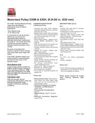
<strong>Motorized</strong> <strong>Pulley</strong> 320L, 320M & 320H, Ø 12.64 <strong>in</strong>. (321 <strong>mm</strong>)Our 12.64” diameter <strong>Motorized</strong> <strong>Pulley</strong>range offers three differentperformance levels for BULKapplications:- L for Light duty- M for Medium duty- H for Heavy dutyIt is important to note the productdifferences and choose theappropriate pulley based onestimated belt tension (radial load.)See page 78. The actual radial loadmust be less than the maximumallowable radial load shown <strong>in</strong> thiscatalog.Be aware of <strong>in</strong>creased belttensions required to drive multi-plythick heavy belts and/or larger beltwidths.If the 12.64” diameter model is notstrong enough to resist estimatedbelt tension, then select 15.91”diameter model.L for Light duty320L is designed for regular andcont<strong>in</strong>uous operat<strong>in</strong>g conditions. It isadvisable to rubber lag these pulleysto grip the belt and limit belt tension.Typical applications are portableconveyors and cross belts <strong>in</strong> mobilecrush<strong>in</strong>g and screen<strong>in</strong>g equipment.320L should not be used for lowspeed high torque feeder conveyors.320L uses motor and gearbox from<strong>220M</strong>.M for Medium dutyThe <strong>in</strong>ternal parts of 320M aredesigned for tough and irregularoperat<strong>in</strong>g conditions (e.g. crush<strong>in</strong>g &screen<strong>in</strong>g applications, asphalt,cement, and concrete plants.)H for Heavy dutyA solid 3-stage gearbox, largershafts, and stronger bear<strong>in</strong>gs enablethe 320H to provide low speed athigh torque and handle irregularload<strong>in</strong>gs <strong>in</strong> harsh operat<strong>in</strong>gconditions.STANDARD SPECIFICATIONof <strong>Motorized</strong> <strong>Pulley</strong>• Crowned mild steel 12.64” diametersteel shell treated with anti-rust wax• Powder coated cast iron bear<strong>in</strong>g hous<strong>in</strong>gs• Mild steel shafts treated with anti-rustwax• Shaft seal<strong>in</strong>g system – degree of protectionIP66/67 (EN60034-5.) Seepage 88.• Powder coated die cast alum<strong>in</strong>um term<strong>in</strong>albox• 3-phase <strong>in</strong>duction motors with thermalprotector• Voltage: All co<strong>mm</strong>on voltages available.Please specify.• Motor w<strong>in</strong>d<strong>in</strong>g <strong>in</strong>sulation Class F• Dynamically balanced rotor• One out of two oil plugs fitted with amagnet to filter the oil <strong>in</strong> 320L• Two oil plugs fitted with a magnet tofilter the oil <strong>in</strong> 320M & 320H• Oil change reco<strong>mm</strong>ended every10,000 operational hours• M<strong>in</strong>imum RL. Please refer to pages33-34• Maximum RL – Please <strong>in</strong>quire.• Non standard RL’s available• To be used <strong>in</strong> horizontal positions ± 5degree onlyPlease note:• Noise-sensitive Areas: High speed 2-pole motors can cause higher noiselevels and are not reco<strong>mm</strong>ended fornoise-sensitive areas• Technical Precautions for Design,Installation, and Ma<strong>in</strong>tenance: pages76-86• Environmental Considerations: page72• Optional Extras: page 31 and backcover• Electrical Connection Diagrams:pages 94-96.STAINLESS STEELoptionsTS9N• Sta<strong>in</strong>less steel shell – AISI 304 range• Sta<strong>in</strong>less steel shafts – AISI 303/4 range• Sta<strong>in</strong>less steel covered bear<strong>in</strong>g hous<strong>in</strong>gs– AISI 316 range• Sta<strong>in</strong>less steel oil plugs – AISI 304range – one out of two with magnet• Sta<strong>in</strong>less steel exterior bolts – AISI 304range• Regreasable labyr<strong>in</strong>th seals with greasenipples <strong>in</strong> sta<strong>in</strong>less steel –AISI 304 range• Shaft seal<strong>in</strong>g system – degree of protectionIP66/67 (EN60034-5).TS10N• As TS9N, but without regreasablelabyr<strong>in</strong>th seals.SEMI-RUST-FREE optionsTS11N• As TS9N, but with crowned mild steelshell treated with anti-rust wax.TS12N• As TS10N, but with crowned mild steelshell treated with anti-rust wax.Other Sta<strong>in</strong>less Options:• FDA & USDA food grade recognized oiland grease are not <strong>in</strong>cluded <strong>in</strong> TS9N toTS12N, but available on request• Complete <strong>Motorized</strong> <strong>Pulley</strong>s <strong>in</strong> acidresistant sta<strong>in</strong>less steel – AISI 316range – available on request.• Special mount<strong>in</strong>g brackets are available.Electrical connection options:• Salt water resistant powder coatedalum<strong>in</strong>um term<strong>in</strong>al box with z<strong>in</strong>c platedexterior bolts• Sta<strong>in</strong>less steel term<strong>in</strong>al box – AISI 304range (max. 5.5 HP)• Straight sta<strong>in</strong>less steel connector withfly<strong>in</strong>g lead – AISI 304 range.Please specify required TS-numberwhen order<strong>in</strong>g Sta<strong>in</strong>less Steel options.www.rulmecacorp.com 30TC101: 03/07
OPTIONAL EXTRAS<strong>Motorized</strong> <strong>Pulley</strong> 320L, 320M & 320HSpecificationAvailabilityTotal sta<strong>in</strong>less steel option AISI 304 range TS9N with regreasable labyr<strong>in</strong>th seals xTotal sta<strong>in</strong>less steel option AISI 304 range TS10N with standard seals xSemi-rust free option TS11N with regreasable labyr<strong>in</strong>th seals xSemi-rust free option TS12N with standard seals xRegreasable labyr<strong>in</strong>th sealsxFood grade oil & grease - FDA & USDA recognizedxDust explosion proof <strong>Motorized</strong> <strong>Pulley</strong>s - ATEX 95 - Zone 22 - for applications handl<strong>in</strong>g of dusty gra<strong>in</strong> etc.Accord<strong>in</strong>g to European Directive 94/9/EC.xTotal acid resistant sta<strong>in</strong>less steel option - AISI 316xBlack rubber lagg<strong>in</strong>g - Standard specifications (See page 80.)5/16” diamond lagg<strong>in</strong>g - Hardness 60 ±5 Shore A < 7.5 HP x1/4” diamond lagg<strong>in</strong>g - Hardness 60 ±5 Shore A 10 HP oWhite smooth rubber lagg<strong>in</strong>g (FDA listed) Oil, fat & grease resistantoSpecial lagg<strong>in</strong>g (e.g. hot vulcanized)oElectromagnetic brake M<strong>in</strong> RL <strong>in</strong>creases by 3.94” xMechanical backstop M<strong>in</strong> RL does not <strong>in</strong>crease for 320L, xM<strong>in</strong>. RL <strong>in</strong>creases by 1.97” for 320 M & 320HxModified for vertical mount<strong>in</strong>goModified for mount<strong>in</strong>g between 5° and 90° (e.g. for magnetic separators)oInsulation class F with standard oil: (Allowable ambient temperature -13°F/+104°F)Std.Insulation class H with synthetic oil: (Allowable ambient temperature -13°F/+120°F)xSpecial motors for applications with no belt contactoLow noise drives for noise sensitive areasxParallel shell (i.e. no crown)xThermal protectorStd.IP66/67 Yellow powder coated alum<strong>in</strong>um term<strong>in</strong>al boxStd.IP66/67 Gray powder coated alum<strong>in</strong>um term<strong>in</strong>al box (food grade approved)xIP66/67 Compact powder coated alum<strong>in</strong>um term<strong>in</strong>al box (food grade approved) < 5.5 HP only oIP66/67 Compact sta<strong>in</strong>less steel term<strong>in</strong>al box - AISI 304 or 316 range < 5.5 HP only oStraight or elbow connector with standard power cord < 5.5 HP only xStraight connector with screened power cord (See page 86 for VFD precautions) < 5.5 HP only xStraight connector with power cord (Sta<strong>in</strong>less steel <strong>in</strong> AISI 304 range) < 5.5 HP only xVoltage: < 5.5 HP dual voltage (230/460) stator (YY/Y w<strong>in</strong>d<strong>in</strong>g) wired for 460v/3ph/60 Hz at term<strong>in</strong>al boxStd.< 5.5 HP dual voltage (230/460) stator (YY/Y w<strong>in</strong>d<strong>in</strong>g) wired for 230v/3ph/60 Hz at term<strong>in</strong>al box x> 7.5 HP s<strong>in</strong>gle voltage (460) stator (Y w<strong>in</strong>d<strong>in</strong>g) wired for 460v/3ph/60 Hz at term<strong>in</strong>al box Std> 7.5 HP s<strong>in</strong>gle voltage (230) stator (YY w<strong>in</strong>d<strong>in</strong>g) wired for 230v/3ph/60 Hz at term<strong>in</strong>al box x2 speed motors xSpecial voltage motorsxS<strong>in</strong>gle phase motorsoCSA approved motorsxx = Optional extraso = An option with certa<strong>in</strong> limitations. Please refer to Technical precautions pages 76-86!Std. = Fitted as standardwww.rulmecacorp.com 31TC101: 03/07
<strong>Motorized</strong> <strong>Pulley</strong> 320L, 320M & 320H, Ø 12.64 <strong>in</strong>. (321 <strong>mm</strong>)Compactterm<strong>in</strong>albox < 5.5HPStandardterm<strong>in</strong>albox<strong>Motorized</strong> <strong>Pulley</strong> with term<strong>in</strong>al boxStraightconnectorElbowconnectorIdler <strong>Pulley</strong> 3 UT320M / UT320H<strong>in</strong> TS9N/TS11N<strong>Motorized</strong> <strong>Pulley</strong> or idler <strong>Pulley</strong> Standard term<strong>in</strong>al Compact term<strong>in</strong>al Straight Elbowbox box < 5.5 HP connector connectorG < 5.5 HP < 5.5 HPA B C D E F G TS9/11 H K W L M N O L M N N1 U V R S TModel <strong>in</strong> <strong>in</strong> <strong>in</strong> <strong>in</strong> <strong>in</strong> <strong>in</strong> <strong>in</strong> <strong>in</strong> <strong>in</strong> <strong>in</strong> <strong>in</strong> <strong>in</strong> <strong>in</strong> <strong>in</strong> <strong>in</strong> <strong>in</strong> <strong>in</strong> <strong>in</strong> <strong>in</strong> <strong>in</strong> <strong>in</strong> <strong>in</strong> <strong>in</strong> <strong>in</strong>320L 12.72 12.56 1.97 1.57 3.78 1.18 0.59 0.75 0.98 2.13 – – – – – 1.61 0.95 3.74 0.55 0.16 1.06 0.79 1.89 0.47320M 12.64 12.56 1.97 1.57 4.92 1.18 0.69 0.89 0.98 2.13 – 3.43 1.06 4.21 4.13 1.61 0.95 3.74 0.55 0.16 1.06 0.79 1.89 0.47320H 12.64 12.56 1.97 1.97 5.83 1.57 0.43 0.81 0.98 2.17 – 3.43 1.06 4.21 4.13 1.61 0.95 3.74 0.55 0.16 1.06 0.79 1.89 0.47UT320M 12.64 12.64 1.97 1.57 4.92 1.18 0.57 0.89 0.98 – 2.05UT320H 12.64 12.64 1.97 1.97 5.83 1.57 0.43 0.81 0.98 – 2.051 A dimension is outer diameter of unlagged pulley shell at pulley centerl<strong>in</strong>e.2 B dimension is outer diameter of unlagged pulley shell at each end of shell.3 Idler pulley shown is non-crowned TS9N/TS11N version with regreasable seals.Mount<strong>in</strong>g brackets<strong>Motorized</strong><strong>Pulley</strong>sMaterialBracketSizePartNumberDimensionsWeightModel320L &320MSteel pa<strong>in</strong>tedSteel NiplatedSta<strong>in</strong>less steelKL41-HD6YA0K6YA0W6YA0UD<strong>in</strong>F<strong>in</strong>I<strong>in</strong>K<strong>in</strong>S<strong>in</strong>T<strong>in</strong>V<strong>in</strong>1.57 1.18 3.31 2.44 0.55 0.79 0.87 1.57 4.33 7.48 1.97 3.27 4.63W1<strong>in</strong>X<strong>in</strong>X1<strong>in</strong>Z<strong>in</strong>Z1<strong>in</strong>lbs320HSteel pa<strong>in</strong>tedSteel NiplatedKL426YA0J6YA0S1.97 1.57 4.76 3.54 0.71 1.18 0.98 1.97 5.91 9.84 2.76 4.33 9.92www.rulmecacorp.com 32TC101: 03/07
<strong>Motorized</strong> <strong>Pulley</strong> 320L, Ø 12.64 <strong>in</strong>. (321 <strong>mm</strong>)MotorPowerHP<strong>Motorized</strong> <strong>Pulley</strong> 320M & 320H, Ø 12.64 <strong>in</strong>. (321 <strong>mm</strong>)MotorPowerHPNo.ofPolesNo.ofPolesNo.Gear ModelStages1 8 2 320L1.52No.Gear ModelStagesNom<strong>in</strong>al beltspeed 1 atFull Load60 Hzfpm7696120150192240300Nom<strong>in</strong>al beltspeed 1 atFull Load60 Hzfpm3 320H 243038481 12602 320M 7696120150192123 320H 24302 320M 3848601.576968 2 320M 120150192240300Actual beltspeed 1 atFull Load60 Hzfpm78100122146186231300Actual beltspeed 1 atFull Load60 Hzfpm253241546983108135166212253241546181103126162203249319BeltPull 2lbs402317259<strong>216</strong>170137105BeltPull 2lbs1241984774581461377291233190148182114441128851752568450368285228186145Max.RadialLoad 3T1 + T2lbsMax.RadialLoad 3T1 + T2lbsM<strong>in</strong>.RLSpecialm<strong>in</strong>.RL1 Use “nom<strong>in</strong>al belt speed” to specify pulley. “Actual belt speed” is presented (for pulley lagged with 1/4” thick rubber) to assist with process design calculations.See Technical Precautions page 77. Note that “actual belt speed” decreases when lagg<strong>in</strong>g is not used due to decreased pulley diameter.2 Belt pull value allows for gearbox loss.3 <strong>Pulley</strong> must not be subjected to radial load exceed<strong>in</strong>g “Maximum radial load” def<strong>in</strong>ed above. See “Belt Tension” section <strong>in</strong> Technical Precautions, page 78.4 Additional <strong>Motorized</strong> <strong>Pulley</strong> and Idler <strong>Pulley</strong> weight, specified per Roller Length: 31.50”< RL < 62.99” Wt = 6.1 lbs/<strong>in</strong>; 62.99”< RL < 78.74” Wt = 11.7 lbs/<strong>in</strong>5 All weights shown above are for pulleys with 1/4” thick lagg<strong>in</strong>g. To calculate unlagged pulley weight subtract 0.5 lbs/<strong>in</strong> of Roller Length from above.*Special “Short Roller Length” Optionwww.rulmecacorp.com 33TC101: 03/07<strong>in</strong><strong>in</strong>RL Dimension <strong>in</strong>ches (RL>78.74” available on request)Weight <strong>in</strong> lbs 5longer15.75 17.72 19.69 21.65 23.62 25.59 27.56 29.53 31.50 than31.50”2585 17.72 - 180* 190 200 209 219 223 239 2496 2 320L 120 132 349 2585 17.72 - 185 194 204 214 224 234 243 2531501921571992942334 2 320L240300384480600243292371462602190159124100772585 15.75 168* 176 185 195 205 215 225 234 2446 2 320L 120 132 476 2585 17.72 - 189 199 209 218 228 238 248 2581501921571994023174 2 320L240300384480600243292371462602259<strong>216</strong>1701371052585 15.75 172* 180 190 200 209 219 229 239 2493 4 2 320L4 4 2 320L5.5 2 2 320L1501922403003844806002403003844806003003844806001571992432923714626022432923714626023143974875835904663803172492001545184333402732105364233452892585 17.72 - 189* 199 208 218 228 238 248 2582585 19.69 - - 207 217 227 237 247 257 2662585 19.69 - - 207 217 227 237 247 257 266RL Dimension <strong>in</strong>ches (RL>78.74” available on request)Weight <strong>in</strong> lbs 5longer17.72 19.69 21.65 23.62 25.59 27.56 29.53 31.50 33.46 than33.467868 21.65 - - 308* 317 329 341 354 366 3784496 19.69 - 251* 261 271 281 291 301 310 320TypeofBracketKL426YA0JKL41-HD6YA0KSee7868 21.65 - - 308* 317 329 341 354 366 378 FootnoteKL426YA0J4496 19.69 - 251* 261 271 281 291 301 310 32060 HzTypeofBracketSeeKL41-HDFootnote6YA0K460 HzKL41-HD6YA0K
<strong>Motorized</strong> <strong>Pulley</strong> 320M & 320H, Ø 12.64 <strong>in</strong>. (321 <strong>mm</strong>)MotorPowerHPNo.ofPolesNo.Gear ModelStagesNom<strong>in</strong>al beltspeed 1 atFull Load60 HzfpmActual beltspeed 1 atFull Load60 HzfpmBeltPull 2lbsMax.RadialLoad 3T1 + T2lbsM<strong>in</strong>.RL<strong>in</strong>RL Dimension <strong>in</strong>ches (RL>78.74” available on request)Weight <strong>in</strong> lbs 5longer17.72 19.69 21.65 23.62 25.59 27.56 29.53 31.50 33.46 than33.46”60 HzTypeofBracket3 320H 384838481655131260 61 102676 81 7742 896 103 6142 320M 120 126 503150 162 389192 203 311240 248 253300 318 19883 320H 38488748242719252 320M607661811505113696 103 9033120150123163752568192 206 4504 2 320M 240300251324368285384 406 228480 498 186600 637 14563 320H48 51 248360 64 196976 78 16132 320M 96 108 1161120 123 1026415019<strong>216</strong>32067746144 2 320M 240300251324503389384 406 311480 498 253600 637 1985.57.5 410 26 3 320H4 2 320M3 320H2 320M3 320H2 320M7696120150192240300384480600961201501922403003844806001501922403003844806007810112316320625132440649863796117152206251324406498637153192235325411501649215116611368103281967051841433826424061971152311259237135694653632069164013449687686294867868 21.65 - - 308* 317 329 341 354 366 3784496 19.69 - 252* 261 271 281 291 301 310 3207868 21.65 - - 308* 317 329 341 354 369 3784496 19.69 - 252* 261 271 281 291 301 310 3204496 19.69 - 229* 239 249 258 268 278 288 2987868 21.65 - - 308* 317 329 341 354 366 3784496 19.69 - 229* 239 249 258 268 278 288 2987868 21.65 - - 308* 317 329 341 354 366 3784496 19.69 - 252* 261 271 281 291 301 310 3207868 21.65 - - 308* 317 329 341 354 366 3784496 19.69 - 252* 261 271 281 291 301 310 3207868 21.65 - - 308* 317 329 341 354 366 3784496 19.69 - - 261 271 281 291 301 310 320SeeFootnote4KL426YA0JKL41-HD6YA0KKL426YA0JKL41-HD6YA0KKL41-HD6YA0KKL426YA0JKL41-HD6YA0KKL426YA0JKL41-HD6YA0KKL426YA0JKL41-HD6YA0KKL426YA0JKL41-HD6YA0KKL41-HDIdler <strong>Pulley</strong> Model UT320M 4496 17.72 118 128 138 148 158 167 177 187 197 See 6YA0KFootnote4 KL42Model UT320H 7868 17.72 131 143 153 163 173 183 193 202 2126YA0J1 Use “nom<strong>in</strong>al belt speed” to specify pulley. “Actual belt speed” is presented (for pulley lagged with 1/4” thick rubber) to assist with process design calculations.See Technical Precautions page 77. Note that “actual belt speed” decreases when lagg<strong>in</strong>g is not used due to decreased pulley diameter.2 Belt pull value allows for gearbox loss.3 <strong>Pulley</strong> must not be subjected to radial load exceed<strong>in</strong>g “Maximum radial load” def<strong>in</strong>ed above. See “Belt Tension” section <strong>in</strong> Technical Precautions, page 78.4 Additional <strong>Motorized</strong> <strong>Pulley</strong> and Idler <strong>Pulley</strong> weight, specified per Roller Length: 31.50”< RL < 62.99” Wt = 6.1 lbs/<strong>in</strong>; 62.99”< RL < 78.74” Wt = 11.7 lbs/<strong>in</strong>5 All weights shown above are for pulleys with 1/4” thick lagg<strong>in</strong>g. To calculate unlagged pulley weight subtract 0.5 lbs/<strong>in</strong> of Roller Length from above.*Special “Short Roller Length” Optionwww.rulmecacorp.com 34TC101: 03/07
<strong>Motorized</strong> <strong>Pulley</strong> 320L, Ø 12.64 <strong>in</strong>. (321 <strong>mm</strong>)Spare parts list and sectional draw<strong>in</strong>gsPos. Description Pos. Description Pos. Description1 Shell2 End hous<strong>in</strong>g with geared rim3 End hous<strong>in</strong>g8 Geared rim9 Rotor p<strong>in</strong>ion10 Input wheel11 Output p<strong>in</strong>ion12 Gear box13 Front shaft14 Rear shaft15 Stator complete15.1 Rotor16 Term<strong>in</strong>al box completeCompact Term<strong>in</strong>al Box17 Nipple20 Cover20.1 Cover with labyr<strong>in</strong>th groove23 Rear flange23.1 Rear flange for backstop23.2 Rear flange for electromagneticbrake24 2 Dust lip seals each side24 1 Double lip seal for labyr<strong>in</strong>thoption25 O-r<strong>in</strong>g26 Bear<strong>in</strong>g27 Bear<strong>in</strong>g28 Bear<strong>in</strong>g29 Bear<strong>in</strong>g (Backstop solution:One-way-bear<strong>in</strong>g)30 Bear<strong>in</strong>g31 Bear<strong>in</strong>g39 Hexagon socket screw40 Hexagon socket screw52 Magnetic oil plug53 Distance washer53.1 Compression nipple59 Countersunk head screw66 Waved spr<strong>in</strong>g washer68 Key70 Toothed washer78 Gasket79 Hold<strong>in</strong>g clip or plastic tie85 Intermediate flange for backstop85.1 Intermediate flange for brakeassembly91 Electromagnetic brake93 Reta<strong>in</strong><strong>in</strong>g r<strong>in</strong>g95 Straight connector96 Elbow connector101 Key104 Distance washer120 Labyr<strong>in</strong>th cover121 Set screw122 O-r<strong>in</strong>g123 Grease nipple143 O-r<strong>in</strong>g146 Special shaped compressionwasher200 Rubber sealwww.rulmecacorp.com 35TC101: 03/07
<strong>Motorized</strong> <strong>Pulley</strong> 320M, Ø 12.64 <strong>in</strong>. (321 <strong>mm</strong>)Spare parts list and sectional draw<strong>in</strong>gsPos. Description Pos. Description Pos. Description1 Shell2 End hous<strong>in</strong>g with geared rim3 End hous<strong>in</strong>g8 Geared rim9 Rotor p<strong>in</strong>ion10 Input wheel11 Output p<strong>in</strong>ion12 Gear box13 Front shaft14 Rear shaft15 Stator complete15.1 Rotor16 Term<strong>in</strong>al box complete17 Nipple20 Cover20.1 Cover with labyr<strong>in</strong>th groove23 Rear flange23.1 Rear flange for backstop/Brake24 2 Dust lip seals each side25 O-r<strong>in</strong>g26 Bear<strong>in</strong>g27 Bear<strong>in</strong>g28 Bear<strong>in</strong>g29 Bear<strong>in</strong>g30 Bear<strong>in</strong>g31 Bear<strong>in</strong>g32 Reta<strong>in</strong><strong>in</strong>g r<strong>in</strong>g33 Reta<strong>in</strong><strong>in</strong>g r<strong>in</strong>g35 Reta<strong>in</strong><strong>in</strong>g r<strong>in</strong>g37 Hexagon socket screw43 Hexagon socket screw44 Hexagon socket screw45 Hexagon head screw46 Hexagon head screw49 Washer52 Magnetic oil plug53 Distance washer53.1 Compression nipple60 Parallel p<strong>in</strong>64 Prevail<strong>in</strong>g torque type hexagonnut66 Waved spr<strong>in</strong>g washer67 Waved spr<strong>in</strong>g washer68 Key70 Waved spr<strong>in</strong>g washer75 Gasket78 Gasket79 Hold<strong>in</strong>g clip or plastic tie85 Intermediate flange for backstop85.1 Intermediate flange for brakeassembly91 Electromagnetic brake93 Reta<strong>in</strong><strong>in</strong>g r<strong>in</strong>g94 Hexagon head screw95 Straight connector96 Elbow connector99 Waved spr<strong>in</strong>g washer101 Key104 Distance washer120 Labyr<strong>in</strong>th cover121 Set screw122 O-r<strong>in</strong>g123 Grease nipple143 O-r<strong>in</strong>g146 Special shaped compressionwasher200 Rubber sealwww.rulmecacorp.com 36TC101: 03/07
<strong>Motorized</strong> <strong>Pulley</strong> 320H, Ø 12.64 <strong>in</strong>. (321 <strong>mm</strong>)Spare parts list and sectional draw<strong>in</strong>gsPos. Description Pos. Description Pos. Description1 Shell2 End hous<strong>in</strong>g with geared rim3 End hous<strong>in</strong>g8 Geared rim9 Rotor p<strong>in</strong>ion10 Input wheel11 Output p<strong>in</strong>ion12 Gear box13 Front shaft14 Rear shaft15 Stator complete15.1 Rotor16 Term<strong>in</strong>al box complete17 Nipple20 Cover front side20.1 Cover with labyr<strong>in</strong>th groove21 Cover – rear side21.1 Cover with labyr<strong>in</strong>th groove23 Rear flange23.1 Rear flange for brake option24 2 Dust lip seals each side25 O-r<strong>in</strong>g26 Bear<strong>in</strong>g27 Bear<strong>in</strong>g28 Bear<strong>in</strong>g29 Bear<strong>in</strong>g20 Cover front side20.1 Cover with labyr<strong>in</strong>th groove21 Cover – rear side21.1 Cover with labyr<strong>in</strong>th groove23 Rear flange23.1 Rear flange for brake option24 2 Dust lip seals each side25 O-r<strong>in</strong>g26 Bear<strong>in</strong>g27 Bear<strong>in</strong>g28 Bear<strong>in</strong>g29 Bear<strong>in</strong>g30 Bear<strong>in</strong>g31 Bear<strong>in</strong>g32 Reta<strong>in</strong><strong>in</strong>g r<strong>in</strong>g33 Reta<strong>in</strong><strong>in</strong>g r<strong>in</strong>g35 Reta<strong>in</strong><strong>in</strong>g r<strong>in</strong>g37 Hexagon socket screw43 Hexagon head screw44 Hexagon head screw45 Hexagon head screw46 Hexagon head screw49 Washer52 Magnetic oil plug53 Distance washer53.1 Compression nipple60 Parallel p<strong>in</strong>64 Hexagon head nut66 Waved spr<strong>in</strong>g washer67 Waved spr<strong>in</strong>g washer68 Key70 Waved spr<strong>in</strong>g washer73 Set screw75 Gasket78 Gasket79 Hold<strong>in</strong>g clip or plastic tie80 Hexagon head screw84 Rear flange for brake85 Intermediate flange for backstop85.1 Intermediate flange for brakeassembly90 Backstop91 Electromagnetic brake93 Reta<strong>in</strong><strong>in</strong>g r<strong>in</strong>g94 Hexagon head screw95 Straight connector96 Elbow connector99 Waved spr<strong>in</strong>g washer101 Key104 Distance washer120 Labyr<strong>in</strong>th cover121 Set screw122 O-r<strong>in</strong>g123 Grease nipple143 O-r<strong>in</strong>g146 Special shaped compressionwasher180 Intermediate p<strong>in</strong>ion shaft181 Intermediate p<strong>in</strong>ion182 Distance bush<strong>in</strong>g183 Washer184 Roller bear<strong>in</strong>g185 Roller bear<strong>in</strong>g186 Key187 Key188 Reta<strong>in</strong><strong>in</strong>g r<strong>in</strong>g190 Reta<strong>in</strong><strong>in</strong>g r<strong>in</strong>g191 Reta<strong>in</strong><strong>in</strong>g r<strong>in</strong>g192 Reta<strong>in</strong><strong>in</strong>g r<strong>in</strong>g193 Distance washer194 Set screw195 Prevail<strong>in</strong>g torque type hexagonnut196 Key197 Reta<strong>in</strong><strong>in</strong>g r<strong>in</strong>g198 Distance r<strong>in</strong>g200 Rubber sealwww.rulmecacorp.com 37TC101: 03/07
<strong>Motorized</strong> <strong>Pulley</strong> 320L, 320M & 320H, Ø 12.64 <strong>in</strong>. (321 <strong>mm</strong>)Sectional draw<strong>in</strong>gsTS9N & TS11NLabyr<strong>in</strong>th Option(valid for 320M)sealed withseal<strong>in</strong>g compoundthe pos. no. <strong>in</strong> brackets(21 & 21.1) is valid for320H 3-stageRegreasableLabyr<strong>in</strong>th OptionTS10N & TS11Nwithout labyr<strong>in</strong>thSta<strong>in</strong>less Steel Option320L TS9NElbow ConnectorElectromagnetic Brake OptionStraight ConnectorBackstop Optionwww.rulmecacorp.com 38TC101: 03/07
<strong>Motorized</strong> <strong>Pulley</strong>sTail DrivesTaconite Ship Load<strong>in</strong>g Term<strong>in</strong>al (Michigan—USA)DEMAG crawler-mounted bucket wheel reclaimer handles taconite pellets at5,000 TPH on 72” wide boom and tail belts at this Escanaba, Michigan facility.Term<strong>in</strong>al operator replaced both orig<strong>in</strong>al Kufnagel conveyor drives with40” diameter Rulmeca <strong>Motorized</strong> <strong>Pulley</strong>s <strong>in</strong> 1985 after 13 years of service.Photo shows tail-mounted 200 HP drive pulley for discharge conveyor.Trap Rock Quarry (New York—USA)Allis M<strong>in</strong>eral Systems delivered this 850 TPH recirculat<strong>in</strong>g crush<strong>in</strong>g andscreen<strong>in</strong>g plant <strong>in</strong> 1994. The tail-mounted 15.75” diameter 15 HP <strong>Motorized</strong><strong>Pulley</strong> drives the 36” wide screen feed belt, <strong>in</strong> tandem with an identicalhead-mounted drive, at 384 fpm. <strong>Motorized</strong> <strong>Pulley</strong>s enabled designers toadhere to the 12’ maximum allowable US highway clearance width. Taildrive is mounted <strong>in</strong> a “Slid<strong>in</strong>g Pedestal” mechanical belt take-up.Technical Precaution: When mount<strong>in</strong>g a motorized pulley <strong>in</strong> a screw takeupalways make sure that pulley centerl<strong>in</strong>e is perpendicular to belt centerl<strong>in</strong>eto avoid overstress<strong>in</strong>g <strong>in</strong>ternal bear<strong>in</strong>gs.Marl Pit at Cement Plant (South Carol<strong>in</strong>a—USA)FAM delivered this crawler-mounted bucket wheel reclaimer <strong>in</strong> 2002 toexcavate marl from a pit adjacent to the producer’s cement plant nearCharleston, South Carol<strong>in</strong>a. It uses tail-mounted 31.5” diameter 100 HP<strong>Motorized</strong> <strong>Pulley</strong>s to drive the 54” wide boom and tail conveyor belts at 600fpm. Externally mounted brakes prevent material from “roll<strong>in</strong>g backwards”when conveyors are stopped because both conveyors can articulate to a 16ºmaximum <strong>in</strong>cl<strong>in</strong>ation.Granite Quarry (Connecticut—USA)Built <strong>in</strong> 2003 by RR Equipment, this mobile recirculat<strong>in</strong>g crush<strong>in</strong>g andscreen<strong>in</strong>g rig uses a tail-mounted 15 HP 15.75” diameter <strong>Motorized</strong> <strong>Pulley</strong>to drive the 36” wide 300 TPH 58’ long screen feed conveyor. Note that useof slender “Telescop<strong>in</strong>g” mechanical belt take-up allows compact and lightweightstructure. This plant adheres to the maximum US highway clearancerequirements of 12’-0” wide by 13’-6” high.Technical Precaution: When mount<strong>in</strong>g a motorized pulley <strong>in</strong> a screw takeupalways make sure that pulley centerl<strong>in</strong>e is perpendicular to belt centerl<strong>in</strong>eto avoid overstress<strong>in</strong>g <strong>in</strong>ternal bear<strong>in</strong>gs.www.rulmecacorp.com 39TC101: 03/07
<strong>Motorized</strong> <strong>Pulley</strong> 400L, 400M & 400H, Ø 15.91 <strong>in</strong>. (404 <strong>mm</strong>)Our 15.91” diameter <strong>Motorized</strong> <strong>Pulley</strong>range offers three differentperformance levels for BULKapplications:- L for Light duty- M for Medium duty- H for Heavy dutyIt is important to note the productdifferences and choose theappropriate pulley based onestimated belt tension (radial load.)See page 78. The actual radial loadmust be less than the maximumallowable radial load shown <strong>in</strong> thiscatalog.Be aware of <strong>in</strong>creased belttensions required to drive multi-plythick heavy belts and/or larger beltwidths.If the 15.91” diameter model is notstrong enough to resist estimatedbelt tension, then select 19.72”diameter model.L for Light duty400L is designed for regular andcont<strong>in</strong>uous operat<strong>in</strong>g conditions. Itis advisable to rubber lag thesepulleys to grip the belt and limit belttension. A popular application is selfclean<strong>in</strong>gmagnetic separators. 400Luses motor and gearbox from 320M.M for Medium duty400M is designed for tough andirregular operat<strong>in</strong>g conditions. 400Mis typically used <strong>in</strong> heavy mobilecrush<strong>in</strong>g & screen<strong>in</strong>g applications aswell as <strong>in</strong> crushed stone, ore,cement, steel, and fertilizer handl<strong>in</strong>g.H for Heavy dutyA solid 3-stage gearbox enables the400H to provide low speed at hightorque and handle irregular load<strong>in</strong>gs<strong>in</strong> harsh operat<strong>in</strong>g conditions.STANDARD SPECIFICATIONof <strong>Motorized</strong> <strong>Pulley</strong>• Crowned mild steel 15.91” diameter steelshell pa<strong>in</strong>ted yellow at a m<strong>in</strong>imum thicknessof 2.4 mils• Bolted powder coated cast iron bear<strong>in</strong>ghous<strong>in</strong>gs and covers, all pa<strong>in</strong>ted yellowat a m<strong>in</strong>imum thickness of 2.4 mils• Mild steel shafts treated w/anti-rust wax• Shaft seal<strong>in</strong>g system - degree of protectionIP66/67 (EN60034-5.) See pg 88.• Powder coated alum<strong>in</strong>um term<strong>in</strong>al boxfor 400L• Cast iron term<strong>in</strong>al box for 400M & 400Hpa<strong>in</strong>ted yellow at m<strong>in</strong>.thickness of 2.4mils• 3-phase <strong>in</strong>duction motors with thermalprotector• Voltage: All co<strong>mm</strong>on voltages available.Please specify.• Motor w<strong>in</strong>d<strong>in</strong>g <strong>in</strong>sulation Class F• Dynamically balanced rotor• Two oil plugs each fitted with a magnetto filter the oil• Oil change reco<strong>mm</strong>ended every 10,000operational hours• M<strong>in</strong>imum RL. Refer to pages 43-44• Maximum RL - Please <strong>in</strong>quire• Non standard RL’s available• To be used <strong>in</strong> horizontal positions ±5degree onlyPlease note:• Noise-sensitive Areas: High speed 2-pole motors can cause higher noise levelsand are not reco<strong>mm</strong>ended for noisesensitiveareas• Technical Precautions for Design,Installation, and Ma<strong>in</strong>tenance: pages76-86• Environmental Considerations: pg 72• Optional Extras: pg 41 and back cover• Electrical Connection Diagrams:pages 94-96.STAINLESS STEEL optionsTS9N• Sta<strong>in</strong>less steel shell - AISI 304 range• Sta<strong>in</strong>less steel shafts - AISI 303/4 range• Sta<strong>in</strong>less steel covered bear<strong>in</strong>g hous<strong>in</strong>gs- AISI 316 range• Regreasable bear<strong>in</strong>g covers withlabyr<strong>in</strong>th grooves and labyr<strong>in</strong>th sealswith grease nipples <strong>in</strong> sta<strong>in</strong>less steel- AISI 304 range• Sta<strong>in</strong>less steel oil plugs - AISI 304range – one out of two with magnet• Sta<strong>in</strong>less steel exterior bolts - AISI 304range• Shaft seal<strong>in</strong>g system – degree of protectionIP66/67 (EN60034-5) See pg 88TS10N• As TS9, but without regreasablelabyr<strong>in</strong>th sealsSEMI-RUST-FREE optionsTS 11N• Pa<strong>in</strong>ted mild steel shell – m<strong>in</strong>. thicknessof 4.7 mils• Sta<strong>in</strong>less steel shafts - AISI 303/4 range• Sta<strong>in</strong>less steel covered cast iron bear<strong>in</strong>ghous<strong>in</strong>g - AISI 316 range• Regreasable bear<strong>in</strong>g covers withlabyr<strong>in</strong>th grooves and grease nipples <strong>in</strong>sta<strong>in</strong>less steel - AISI 304 range• Sta<strong>in</strong>less steel oil plugs – AISI 304range - one out of two with magnet• Sta<strong>in</strong>less steel exterior bolts - AISI 304range• Shaft seal<strong>in</strong>g system - degree of protectionIP66/67 (EN60034-5)• Powder coated term<strong>in</strong>al box for 400L• Pa<strong>in</strong>ted term<strong>in</strong>al box - m<strong>in</strong>. thickness of4.7 mils for 400M & 400HTS12N• As TS11N, but without regreasableseals.• Covers - standardOther Sta<strong>in</strong>less Options:• FDA & USDA food grade recognized oiland grease are not <strong>in</strong>cluded <strong>in</strong> TS9N -TS12N, but available on request• Complete <strong>Motorized</strong> <strong>Pulley</strong>s <strong>in</strong> acidresistant sta<strong>in</strong>less steel - AISI 316range - available on request.• Special mount<strong>in</strong>g brackets availableElectrical connection options:• Salt water resistant powder coated alum<strong>in</strong>umterm<strong>in</strong>al box with z<strong>in</strong>c platedexterior bolts• Sta<strong>in</strong>less steel term<strong>in</strong>al box - AISI 304range (400L < 5.5 HP only)• Straight sta<strong>in</strong>less steel connector withfly<strong>in</strong>g lead - AISI 304 range < 5.5 HPonly.Please specify required TS-numberwhen order<strong>in</strong>g Sta<strong>in</strong>less Steeloptions..www.rulmecacorp.com 40TC101: 03/07
OPTIONAL EXTRAS<strong>Motorized</strong> <strong>Pulley</strong> 400L, 400M & 400HSpecificationAvailabilityTotal sta<strong>in</strong>less steel option AISI 304 range TS9N with regreasable labyr<strong>in</strong>th seals xTotal sta<strong>in</strong>less steel option AISI 304 range TS10N with standard seals xSemi-rust free option TS11N with regreasable labyr<strong>in</strong>th seals xSemi-rust free option TS12N with standard seals xRegreasable labyr<strong>in</strong>th sealsxFood grade oil & grease - FDA & USDA recognizedxDust explosion proof <strong>Motorized</strong> <strong>Pulley</strong>s - ATEX 95 - Zone 22 - for applications handl<strong>in</strong>g of dusty gra<strong>in</strong> etc.Accord<strong>in</strong>g to European Directive 94/9/EC.xTotal acid resistant sta<strong>in</strong>less steel option - AISI 316 rangexBlack rubber lagg<strong>in</strong>g - Standard specifications (See page 80.)5/16” full diamond lagg<strong>in</strong>g - Hardness 60 ±5 Shore A < 15 HP o5/16” partial diamond lagg<strong>in</strong>g - Hardness 60 ±5 Shore A 20 HP oWhite smooth rubber lagg<strong>in</strong>g (FDA listed) - Oil, fat & grease resistantoSpecial lagg<strong>in</strong>g (e.g. hot vulcanized)oElectromagnetic brake M<strong>in</strong> RL <strong>in</strong>creases by 3.94” xMechanical backstop M<strong>in</strong>. RL <strong>in</strong>creases by 1.97” for 400L xM<strong>in</strong>. RL = 29.53” for 400MxM<strong>in</strong>. RL = 31.50” for 400HxModified for vertical mount<strong>in</strong>goModified for mount<strong>in</strong>g between 5° and 90°oInsulation class F with standard oil: (Allowable ambient temperature -13°F/+104°F)Std.Insulation class H with synthetic oil: (Allowable ambient temperature -13°F/+120°F)xSpecial motors for applications with no belt contactoLow noise drives for noise sensitive areasxParallel shell (i.e. no crown)xThermal protectorStd.IP66/67 Standard yellow powder coated alum<strong>in</strong>um term<strong>in</strong>al box 400L Std.IP66/67 Optional gray powder coated alum<strong>in</strong>um term<strong>in</strong>al box (food grade approved) 400L xIP66/67 Standard yellow powder coated cast iron term<strong>in</strong>al box 400M & 400H Std.Straight or elbow connector with standard power cord < 5.5 HP only xStraight connector with screened power cord (See page 86 for VFD precautions) < 5.5 HP only xStraight connector with power cord (Sta<strong>in</strong>less steel <strong>in</strong> AISI 304 range) < 5.5 HP only xVoltage: < 5.5 HP dual voltage (230/460) stator (YY/Y w<strong>in</strong>d<strong>in</strong>g) wired for 460v/3ph/60 Hz at term<strong>in</strong>al boxStd.< 5.5 HP dual voltage (230/460) stator (YY/Y w<strong>in</strong>d<strong>in</strong>g) wired for 230v/3ph/60 Hz at term<strong>in</strong>al box x> 7.5 HP s<strong>in</strong>gle voltage (460) stator (Y w<strong>in</strong>d<strong>in</strong>g) wired for 460v/3ph/60 Hz at term<strong>in</strong>al box Std> 7.5 HP s<strong>in</strong>gle voltage (230) stator (YY w<strong>in</strong>d<strong>in</strong>g) wired for 230v/3ph/60 Hz at term<strong>in</strong>al box x2 speed motors xSpecial voltage motorsxCSA approved motorsxx = Optional extraso = An option with certa<strong>in</strong> limitations. Please refer to Technical precautions pages 76-86.Std. = Fitted as standardwww.rulmecacorp.com 41TC101: 03/07
<strong>Motorized</strong> <strong>Pulley</strong> 400L, 400M & 400H, Ø 15.91 <strong>in</strong>. (404 <strong>mm</strong>)400LCompactAl term<strong>in</strong>albox < 5.5 HP400M & 400Hstandard castiron term<strong>in</strong>albox400LstandardAl term<strong>in</strong>albox<strong>Motorized</strong> <strong>Pulley</strong> with term<strong>in</strong>al boxStraightconnectorElbowconnectorIdler <strong>Pulley</strong> 3UT400L / UT400M / UT400H<strong>Motorized</strong> <strong>Pulley</strong> or idler <strong>Pulley</strong> Standard term<strong>in</strong>al Compact term<strong>in</strong>al Straight Elbowbox box
<strong>Motorized</strong> <strong>Pulley</strong> 400L, Ø 15.91 <strong>in</strong>. (404 <strong>mm</strong>)MotorPowerHPNo.ofPolesNo.Gear ModelStages3 4 2 400L4 4 2 400L5.5 4 2 400L7.5 4 2 400L10 2 2 400LNom<strong>in</strong>al beltspeed 1 atFull Load60 Hzfpm192240300384480600150192240300384480600192240300384480600300384480600384480600768Actual beltspeed 1 atFull Load60 Hzfpm201240303395498613163201240303395498613201240303395498613303395498613402481607791BeltPull 2lbs460385305234186151771627524416319253206836700554425338274778598474386784655520399Max.RadialLoad 3T1 + T2lbsM<strong>in</strong>.RL<strong>in</strong>RL Dimension <strong>in</strong>ches (RL>78.74” available on request)Weight <strong>in</strong> lbs 560 Hzlonger19.69 21.65 23.62 25.59 27.56 29.53 31.50 33.46 35.43 37.40 than37.404496 19.69 276* 288 300 312 324 337 349 361 373 3854496 19.69 276* 288 300 312 324 337 349 361 373 3854496 19.69 298* 310 322 334 346 359 371 383 395 4074496 19.69 298* 310 322 334 346 359 371 383 395 4074496 19.69 298* 310 322 334 346 359 371 383 395 407TypeofBracketSeeKL41-HDFootnote6YA0K4Idler <strong>Pulley</strong> Model UT400L 4496 19.69 188 200 212 224 236 249 261 273 285 297SeeFootnoteKL41-HD6YA0K41 Use “nom<strong>in</strong>al belt speed” to specify pulley. “Actual belt speed” is presented (for pulley lagged with 5/16” thick rubber) to assist with process design calculations.See Technical Precautions page 77. Note that “actual belt speed” decreases when lagg<strong>in</strong>g is not used due to decreased pulley diameter.2 Belt pull value allows for gearbox loss.3 <strong>Pulley</strong> must not be subjected to radial load exceed<strong>in</strong>g “Maximum radial load” def<strong>in</strong>ed above. See “Belt Tension” section <strong>in</strong> Technical Precautions, page 78.4 Additional <strong>Motorized</strong> <strong>Pulley</strong> and Idler <strong>Pulley</strong> weight, specified per Roller Length: 37.40”< RL < 78.74” Wt = 6.2 lbs/<strong>in</strong>.5 All weights shown above are for pulleys with 5/16” thick lagg<strong>in</strong>g. To calculate unlagged pulley weight subtract 0.6 lbs/<strong>in</strong> of Roller Length from above.*Special “Short Roller Length” Optionwww.rulmecacorp.com 43TC101: 03/07
<strong>Motorized</strong> <strong>Pulley</strong> 400M & 400H, Ø 15.91 <strong>in</strong>. (404 <strong>mm</strong>)PowerHPMotorNo.ofPoles3 85.5 87.5 41015 420 2No.GearStagesModel3 400H2 400M3 400H2 400M3 400H2 400M6 3 400H4 2 400M3 400H2 400M3 400H2 400MNom<strong>in</strong>al beltspeed 1 atFull Load60 Hzfpm384860769612015019224030038448607696120150192240300384769612015019224030038448060076896120150192240300384480600768150192240300384480600768192240300384480600768Actual beltspeed 1 atFull Load60 Hzfpm4454648210112115219724830739054648110112115219724830739087107128163201240303395498613778108140177201240303395498613778162211265303395498613778214257323402481607791BeltPull 2lbs21211725144211319207706104683713022383137262320791673139911088516755484322651215618031413115096276258546537729729232244178215681311103979863351540528592194174215251170929754594294024591949156813111039798Max.RadialLoad 3T1 + T2lbsM<strong>in</strong>.RL<strong>in</strong>RL Dimension <strong>in</strong>ches (RL>78.74” available on request)Weight <strong>in</strong> lbs 560 Hzlonger23.62 25.59 27.56 29.53 31.50 33.46 35.43 37.40 39.37 than39.3711,250 25.59 - 533 547 563 577 591 605 619 6349,100 23.62 442 456 470 485 500 514 528 542 55711,250 25.59 - 553 567 582 597 611 625 639 6549,100 23.62 462 476 490 505 519 534 548 562 57611,250 25.59 - 533 547 563 577 591 605 619 6349,100 23.62 442 456 470 485 500 514 528 542 55711,250 29.53 - - - 602 616 631 645 659 6739,100 23.62 455 469 483 499 513 527 541 556 57011,250 29.53 - - - 602 616 631 645 659 6739,100 27.56 - - 510* 525 539 554 568 582 59611,250 29.53 - - - 602 616 631 645 659 6739,100 27.56 - - 510* 525 539 554 568 582 596SeeFootnote4TypeofBracketKL606YA09Idler <strong>Pulley</strong> UT400M 9,100 23.62 264 277 294 309 323 333 347 362 376 SeeFootnoteKL606YA09UT400H 11,250 25.59 - 288 305 320 334 344 358 373 38741 Use “nom<strong>in</strong>al belt speed” to specify pulley. “Actual belt speed” is presented (for pulley lagged with 5/16” thick rubber) to assist with process design calculations.See Technical Precautions page 77. Note that “actual belt speed” decreases when lagg<strong>in</strong>g is not used due to decreased pulley diameter.2 Belt pull value allows for gearbox loss.3 <strong>Pulley</strong> must not be subjected to radial load exceed<strong>in</strong>g “Maximum radial load” def<strong>in</strong>ed above. See “Belt Tension” section <strong>in</strong> Technical Precautions, page 78.4 Additional <strong>Motorized</strong> <strong>Pulley</strong> and Idler <strong>Pulley</strong> weight, specified per Roller Length: 39.37”< RL < 78.74” Wt = 7.3 lbs/<strong>in</strong>.5 All weights shown above are for pulleys “fully lagged” with 5/16” thick rubber. For “partially lagged” pulleys add 5% to 10% to the weights shown above.See page 80 for “partial lagg<strong>in</strong>g.” To calculate unlagged pulley weight subtract 0.6 lbs/<strong>in</strong> of Roller Length from above.*Special “Short Roller Length” Optionwww.rulmecacorp.com 44TC101: 03/07
<strong>Motorized</strong> <strong>Pulley</strong> 400L, Ø 15.91 <strong>in</strong>. (404 <strong>mm</strong>)Spare parts list and sectional draw<strong>in</strong>gsPos. Description Pos. Description Pos. Description1 Shell2 End hous<strong>in</strong>g with geared rim8 Geared rim9 Rotor p<strong>in</strong>ion10 Input wheel11 Output p<strong>in</strong>ion12 Gear box – cast alum<strong>in</strong>um13 Front shaft14 Rear shaft15 Stator complete15.1 Rotor16 Term<strong>in</strong>al box complete17 Nipple20 Cover – front side20.1 Cover with labyr<strong>in</strong>th groove21 Cover – rear side21.1 Cover with labyr<strong>in</strong>th groove23 Rear flange24 2 Dust lip seals each side23 1 Double lip seals for labyr<strong>in</strong>thoption26 Bear<strong>in</strong>g27 Bear<strong>in</strong>g28 Bear<strong>in</strong>g29 Bear<strong>in</strong>g30 Bear<strong>in</strong>g31 Bear<strong>in</strong>g32 Reta<strong>in</strong><strong>in</strong>g r<strong>in</strong>g33 Reta<strong>in</strong><strong>in</strong>g r<strong>in</strong>g37 Hexagon socket screw38 Hexagon socket screw43 Hexagon screw44 Hexagon screw45 Hexagon socked head screw46 Hexagon screw49 Washer50 Washer52 Magnetic oil plug53 Distance washer53.1 Compression nipple60 Parallel p<strong>in</strong>64 Prevail<strong>in</strong>g torque type hexagonnut66 Waved spr<strong>in</strong>g washer67 Waved spr<strong>in</strong>g washer68 Key73 Set screw75 Gasket76 Gasket77 Gasket78 Gasket79 Hold<strong>in</strong>g clip or plastic tie85 Intermediate flange for backstop85.1 Intermediate flange for brakeassembly90 Backstop91 Electromagnetic brake93 Reta<strong>in</strong><strong>in</strong>g r<strong>in</strong>g94 Hexagon head screw95 Straight connector96 Elbow connector99 Waved spr<strong>in</strong>g washer101 Key104 Distance washer120 Labyr<strong>in</strong>th cover121 Set screw122 O-r<strong>in</strong>g123 Grease nipple143 O-r<strong>in</strong>g146 Special compression washer200 Rubber sealwww.rulmecacorp.com 45TC101: 03/07
<strong>Motorized</strong> <strong>Pulley</strong> 400M, Ø 15.91 <strong>in</strong>. (404 <strong>mm</strong>)Spare parts list and sectional draw<strong>in</strong>gsPos. Description Pos. Description Pos. Description1 Shell2 End hous<strong>in</strong>g with geared rim3 End hous<strong>in</strong>g8 Geared rim9 Rotor p<strong>in</strong>ion10 Input wheel11 Output p<strong>in</strong>ion12 Gear box – cast alum<strong>in</strong>um13 Front shaft14 Rear shaft15 Stator complete15.1 Rotor16 Term<strong>in</strong>al box complete17 Nipple20 Cover – front side20.1 Cover with labyr<strong>in</strong>th groove21 Cover – rear side21.1 Cover with labyr<strong>in</strong>th groove23 Rear flange24 2 Dust lip seals each side26 Bear<strong>in</strong>g27 Bear<strong>in</strong>g28 Bear<strong>in</strong>g29 Bear<strong>in</strong>g30 Bear<strong>in</strong>g31 Bear<strong>in</strong>g32 Reta<strong>in</strong><strong>in</strong>g r<strong>in</strong>g36 Hexagon head screw45 Hexagon screw50 Waved spr<strong>in</strong>g washer52 magnetic oil plug37 Hexagon socket screw38 Hexagon socket screw43 Hexagon screw44 Hexagon screw52 Magnetic oil plug53 Distance washer66 Waved spr<strong>in</strong>g washer67 Waved spr<strong>in</strong>g washer70 Spr<strong>in</strong>g washer73 Set screw75 Gasket76 Gasket77 Gasket78 Gasket85 Intermediate flange90 Backstop91 Electromagnetic brake93 Reta<strong>in</strong><strong>in</strong>g r<strong>in</strong>g94 Hexagon head screw99 Waved spr<strong>in</strong>g washer101 Key104 Distance washer120 Labyr<strong>in</strong>th cover121 Set screw122 O-r<strong>in</strong>g123 Grease nipplewww.rulmecacorp.com 46TC101: 03/07
<strong>Motorized</strong> <strong>Pulley</strong> 400H, Ø 15.91 <strong>in</strong>. (404 <strong>mm</strong>)Spare parts list and sectional draw<strong>in</strong>gsPos. Description Pos. Description Pos. Description1 Shell2 End hous<strong>in</strong>g with geared rim8 Geared rim9 Rotor p<strong>in</strong>ion10 Input wheel11 Output p<strong>in</strong>ion12 Gear box – cast iron13 Rear shaft14 Front shaft15 Stator complete15.1 Rotor16 Term<strong>in</strong>al box complete17 Nipple20 Cover rear side20.1 Cover with labyr<strong>in</strong>th groove21 Cover front side21.1 Cover with labyr<strong>in</strong>th groove23 Rear flange24 2 Dust lip seals26 Bear<strong>in</strong>g27 Bear<strong>in</strong>g28 Bear<strong>in</strong>g30 Bear<strong>in</strong>g31 Bear<strong>in</strong>g32 Reta<strong>in</strong><strong>in</strong>g r<strong>in</strong>g33 Reta<strong>in</strong><strong>in</strong>g r<strong>in</strong>g36 Hexagon socket screw37 Hexagon socket screw38 Hexagon socket screw43 Hexagon socket screw44 Hexagon socket screw45 Hexagon socket screw50 Waved spr<strong>in</strong>g washer52 Magnetic oil plug53 Distance washer66 Waved spr<strong>in</strong>g washer72 Taper grooved p<strong>in</strong>73 Set screw75 Gasket76 Gasket77 Gasket78 Gasket85 Intermediate flange for brakeassembly90 Backstop91 Electromagnetic brake93 Reta<strong>in</strong><strong>in</strong>g r<strong>in</strong>g94 Hexagon head screw99 Waved spr<strong>in</strong>g washer101 Key104 Distance washer120 Labyr<strong>in</strong>th cover121 Fix<strong>in</strong>g bolt122 O-r<strong>in</strong>g123 Grease nipple180 Intermediate p<strong>in</strong>ion shaft181 Intermediate wheel182 Distance washer183 Distance washer184 Roller bear<strong>in</strong>g185 Roller bear<strong>in</strong>g186 Key187 Key188 Reta<strong>in</strong><strong>in</strong>g r<strong>in</strong>g190 Reta<strong>in</strong><strong>in</strong>g r<strong>in</strong>g191 Reta<strong>in</strong><strong>in</strong>g r<strong>in</strong>g194 Set screw196 Key197 Reta<strong>in</strong><strong>in</strong>g r<strong>in</strong>gwww.rulmecacorp.com 47TC101: 03/07
<strong>Motorized</strong> <strong>Pulley</strong> 400L, 400M & 400H, Ø 15.91 <strong>in</strong>. (404 <strong>mm</strong>)Sectional draw<strong>in</strong>gs400M - 400H Backstop Option400M - 400H Electromagnetic Brake Option400L: TS9N & TS11NLabyr<strong>in</strong>th Option400M - 400H: TS9N & TS11NLabyr<strong>in</strong>th Option400L Electromagnetic Brake Option400M - 400H: TS10N & TS12NSta<strong>in</strong>less Steel Option without Labyr<strong>in</strong>th400L Backstop Optionwww.rulmecacorp.com 48TC101: 03/07
<strong>Motorized</strong> <strong>Pulley</strong>sHopper Feeder DrivesLimestone Quarry (Georgia—USA)Two 15.75” diameter 5.5 HP <strong>Motorized</strong> <strong>Pulley</strong>s were <strong>in</strong>stalled 1994 to automatically“choke feed” tertiary gyratory crushers, work<strong>in</strong>g <strong>in</strong> comb<strong>in</strong>ationwith variable frequency drives (VFD) and ultrasonic sensors. Each pulleydrives a 36” wide belt at a maximum speed of 120 FPM to transfer 4” m<strong>in</strong>usproduct at 425 TPH.Technical Precaution: When driv<strong>in</strong>g motorized pulley with VFD on 460 volt3 phase 60 Hz power supply, always restrict frequencies to allowable frequencyspectrum of 12 to 66 Hz to avoid torque loss and heat build-up. FilterVFD output if VFD is more than 30’ from motorized pulley to avoid resonance-<strong>in</strong>ducedvoltage spikes.Foundry for Railroad Truck Cast<strong>in</strong>gs (Ohio—USA)Installed at first American Steel Foundries (now Alliance Cast<strong>in</strong>gs Company)plant <strong>in</strong> 1980, this 15.75” diameter 10 HP motorized pulley transfers recycledfoundry sand to mold area at 150 TPH. Conveyor makes 30 start/stopsper hour. Ambient environment is hot (>104º F) and conta<strong>in</strong>s a high percentageof airborne abrasive particulate. Photo taken <strong>in</strong> 1993, after 13years of service.Technical Precaution: When <strong>in</strong>stall<strong>in</strong>g motorized pulley <strong>in</strong> hot environment(>104º F), specify optional Class H motor w<strong>in</strong>d<strong>in</strong>gs and synthetic oil. ContactRulmeca if ambient temperature will exceed 120º F.Taconite Process<strong>in</strong>g Plant (M<strong>in</strong>nesota—USA)Two limestone feeder belt drives beneath storage silo were converted from20-year-old DC motors to AC-powered motorized pulleys <strong>in</strong> 1995. An ABBVFD drives each 19.72” diameter 5.5 HP motorized pulley to a maximum of120 FPM. Conversion enabled plant operator to elim<strong>in</strong>ate exposed motorsand gearboxes and replace SCRs, relays, and timer banks with VFDs <strong>in</strong>control panel.Technical Precaution: When driv<strong>in</strong>g motorized pulley with VFD on 460 volt3 phase 60 Hz power supply, always restrict frequencies to allowable frequencyspectrum of 12 to 66 Hz to avoid torque loss and heat build-up. FilterVFD output if VFD is more than 30’ from motorized pulley to avoid resonance-<strong>in</strong>ducedvoltage spikes.Electric Power Plant (Connecticut—USA)Designed and built <strong>in</strong> 1989 by ABB, this refuse derived fuel (RDF) plant usestwo 12’ diameter tro<strong>mm</strong>els to separate light burnable trash from landfillmaterial. A 24.80” diameter 30 HP <strong>Motorized</strong> <strong>Pulley</strong> drives each steeply<strong>in</strong>cl<strong>in</strong>ed tro<strong>mm</strong>el feed conveyor at 300 FPM. Each 100’ long 48” wide feedbelt is fitted with cleats and sidewalls to elevate 250 TPH of refuse at 45º<strong>in</strong>cl<strong>in</strong>ation.Technical Precaution: When us<strong>in</strong>g motorized pulley to drive a s<strong>in</strong>gle directionbelt on an <strong>in</strong>cl<strong>in</strong>e use built-<strong>in</strong> mechanical backstop to prevent materialfrom roll<strong>in</strong>g downhill when belt stops.www.rulmecacorp.com 49TC101: 03/07
<strong>Motorized</strong> <strong>Pulley</strong> 500L, 500M & 500H, Ø 19.72 <strong>in</strong>. (501 <strong>mm</strong>)Our 19.72” diameter <strong>Motorized</strong> <strong>Pulley</strong>range offers three differentperformance levels for BULKapplications:- L for Light duty- M for Medium duty- H for Heavy dutyIt is important to notice the productdifferences and choose theappropriate pulley based onestimated belt tension (radial load.)See page 78. The actual radial loadmust be less than the maximumallowable radial load shown <strong>in</strong> thiscatalog.Be aware of <strong>in</strong>creased belttensions required to drive multi-plythick heavy belts and/or larger beltwidths.If the 19.72” diameter model is notstrong enough to resist estimatedbelt tension, then select 24.80”diameter model.L for Light duty500L is designed for tough andirregular operat<strong>in</strong>g conditions. 500Lis typically used <strong>in</strong> heavy mobilecrush<strong>in</strong>g & screen<strong>in</strong>g applications aswell as <strong>in</strong> crushed stone, ore, cement,steel, and fertilizer handl<strong>in</strong>g. 500Luses motor and gearbox from 400M.Note that 500L outer dimensions donot match 500H (Former modelsTM500 and TM501).M for Medium dutyA solid 3-stage gearbox enables the500M to provide low speed at hightorque and handle irregular load<strong>in</strong>gs<strong>in</strong> harsh operat<strong>in</strong>g conditions. 500Muses motor and gearbox from 400H.Note that 500M outer dimensions donot match 500H (Former modelsTM500 and TM501).H for Heavy duty500H has strongest <strong>in</strong>ternalcomponents <strong>in</strong> this diameter withgearbox, shaft, and bear<strong>in</strong>gsdesigned for tough, irregular, andextreme operat<strong>in</strong>g conditions.STANDARD SPECIFICATIONof <strong>Motorized</strong> <strong>Pulley</strong>• Crowned mild steel 19.72” diametersteel shell pa<strong>in</strong>ted yellow at a m<strong>in</strong>imumthickness of 2.4 mils• Bolted powder coated cast iron bear<strong>in</strong>ghous<strong>in</strong>gs and covers, all pa<strong>in</strong>ted yellowat a m<strong>in</strong>imum thickness of 2.4 mils• Mild steel shafts• Shaft seal<strong>in</strong>g system - degree of protectionIP66/67 (EN60034-5.) Seepage 88.• Cast iron term<strong>in</strong>al box for pa<strong>in</strong>ted yellowat m<strong>in</strong>.thickness of 2.4 mils• 3-phase <strong>in</strong>duction motors with thermalprotector• Voltage: All co<strong>mm</strong>on voltages available.Please specify.• Motor w<strong>in</strong>d<strong>in</strong>g <strong>in</strong>sulation Class F• Dynamically balanced rotor• Two oil plugs each fitted with a magnetto filter the oil• Black pa<strong>in</strong>ted mount<strong>in</strong>g brackets(KL60) for 500L and 500M available onrequest• Yellow pa<strong>in</strong>ted mount<strong>in</strong>g brackets(AL65 & ALO65) <strong>in</strong>cluded with 500H• Oil change reco<strong>mm</strong>ended every10,000 operational hours• M<strong>in</strong>imum RL. Refer to pages 53 & 58• Maximum RL - Please <strong>in</strong>quire• Non standard RL’s available• To be used <strong>in</strong> horizontal positions ±5degree onlyPlease note:• Noise-sensitive Areas: High speed 2-pole motors can cause higher noiselevels and are not reco<strong>mm</strong>ended fornoise-sensitive areas• Technical Precautions for Design,Installation, and Ma<strong>in</strong>tenance:pages 76-86• Environmental Considerations:page 72• Optional Extras: page 51 and backcover• Electrical Connection Diagrams:pages 94-96.SEMI-RUST-FREE optionsTS11 – (500L & 500M)• Pa<strong>in</strong>ted mild steel shell at m<strong>in</strong>imumthickness of 4.7 mils• Sta<strong>in</strong>less steel shafts – AISI 303/4range• Pa<strong>in</strong>ted cast iron end hous<strong>in</strong>gs at m<strong>in</strong>imumthickness of 4.7 mils• Sta<strong>in</strong>less steel bear<strong>in</strong>g covers withlabyr<strong>in</strong>th grooves and grease nipples –AISI 304 range• Z<strong>in</strong>c plated oil plugs each with magnet• Z<strong>in</strong>c plated exterior bolts• Shaft seal<strong>in</strong>g system – degree of protectionIP66/67 (EN60034-5.) Seepage 88.• Pa<strong>in</strong>ted term<strong>in</strong>al box at m<strong>in</strong>imum thicknessof 4.7 mils• Nickel plated mount<strong>in</strong>g brackets areavailableTS11 – (500H)• Pa<strong>in</strong>ted mild steel shell at m<strong>in</strong>imumthickness of 4.7 mils• Pa<strong>in</strong>ted cast iron end hous<strong>in</strong>gs at m<strong>in</strong>imumthickness of 4.7 mils• Sta<strong>in</strong>less steel covers with labyr<strong>in</strong>thgrooves – AISI 304 range• Nitrided shaft sleeves• Z<strong>in</strong>c-plated oil plugs - each with magnet• Z<strong>in</strong>c-plated exterior bolts• Shaft seal<strong>in</strong>g system – degree of protectionP66/67 (EN60034-5) See pg 88.• Pa<strong>in</strong>ted term<strong>in</strong>al box at m<strong>in</strong>imum thicknessof 4.7 mils• Nickel plated mount<strong>in</strong>g brackets withlabyr<strong>in</strong>th groovesTS12• As TS11, but without regreasableseals.• Covers - standardPlease note:• FDA & USDA food grade recognized oiland grease are not <strong>in</strong>cluded <strong>in</strong> TS11 &TS12, but available on requestPlease specify required TS-numberwhen order<strong>in</strong>g Sta<strong>in</strong>less Steeloptions.www.rulmecacorp.com 50TC101: 03/07
OPTIONAL EXTRAS<strong>Motorized</strong> <strong>Pulley</strong> 500L, 500M & 500HSpecificationAvailabilitySemi-rust-free option TS11 with regreasable labyr<strong>in</strong>th seals xSemi-rust-free option TS12 with standard seals xRegreasable labyr<strong>in</strong>th sealsxDust explosion proof <strong>Motorized</strong> <strong>Pulley</strong>s - ATEX 95 - Zone 22 - for applicationshandl<strong>in</strong>g of dusty gra<strong>in</strong> etc. Accord<strong>in</strong>g to European Directive 94/9/EC.xStandard black rubber lagg<strong>in</strong>g (See page 80.)3/8” full smooth lagg<strong>in</strong>g - Hardness 60 ±5 Shore A o3/8” full diamond lagg<strong>in</strong>g - Hardness 60 ±5 Shore A o3/8” partial smooth lagg<strong>in</strong>g - Hardness 60 ±5 Shore A oWhite smooth rubber lagg<strong>in</strong>g (FDA listed) - Oil, fat & grease resistantoSpecial lagg<strong>in</strong>g - e.g. hot vulcanized, partial, and ceramic (See page 80.)oInternal electromagnetic brake (not available <strong>in</strong> 500H) M<strong>in</strong>. RL <strong>in</strong>creases by 3.94” for 500L and 500M xExternal brake shaft (for mechanical brake by others) Only available <strong>in</strong> 500H xMechanical backstop M<strong>in</strong>. RL = 29.53” for 500L xM<strong>in</strong>. RL = 31.50” for 500MxM<strong>in</strong>. RL = 29.53” for 500HxInsulation class F with standard oil: (allowable ambient temperature: -13°F/+104°F)Std.Insulation class H with synthetic oil: (allowable ambient temperature: -13°F/+120°F)xParallel shellxThermal protectorVoltage: S<strong>in</strong>gle voltage (460) stator (Y w<strong>in</strong>d<strong>in</strong>g) wired for 460v/3ph/60 Hz at term<strong>in</strong>al boxIP66/67 Standard yellow powder coated cast iron term<strong>in</strong>al boxSpecial voltage motorsCSA approved motorsx = Optional extraso = An option with certa<strong>in</strong> limitations. Please refer to Technical precautions pages 76-86.Std. = Fitted as standardStd.Std.Std.xxwww.rulmecacorp.com 51TC101: 03/07
<strong>Motorized</strong> <strong>Pulley</strong> 500L & 500M, Ø 19.72 <strong>in</strong>. (501 <strong>mm</strong>)<strong>Motorized</strong> <strong>Pulley</strong>with term<strong>in</strong>al boxIdler <strong>Pulley</strong> 3UT400M & UT400H<strong>Motorized</strong> <strong>Pulley</strong> or Idler <strong>Pulley</strong>Standard term<strong>in</strong>al boxA B C D E F G H K L M N OModel <strong>in</strong> <strong>in</strong> <strong>in</strong> <strong>in</strong> <strong>in</strong> <strong>in</strong> <strong>in</strong> <strong>in</strong> <strong>in</strong> <strong>in</strong> <strong>in</strong> <strong>in</strong> <strong>in</strong>500L & 500M 19.72 19.57 1.97 2.36 7.64 1.77 0.91 0.98 1.97 3.94 1.44 – 6.14UT400M & UT400H 15.91 15.91 1.97 2.36 6.61 1.77 0.79 0.98 –1 A dimension is outer diameter of unlagged pulley shell at pulley centerl<strong>in</strong>e.2 B dimension is outer diameter of unlagged pulley shell at each end of shell.3 Idler pulley shown is non-crowned version.<strong>Motorized</strong><strong>Pulley</strong>s &IdlersMaterialBracketSizePartNumberDimensionsMount<strong>in</strong>g bracketWeightModel500L, 500M,UT400M, &UT400HSteel pa<strong>in</strong>tedSteelNi platedKL606YA096YA0DD<strong>in</strong>F<strong>in</strong>I<strong>in</strong>K<strong>in</strong>S<strong>in</strong>T<strong>in</strong>V<strong>in</strong>2.36 1.77 5.12 3.54 0.71 1.18 0.98 1.97 5.91 10.63 2.76 4.53 10.58W1<strong>in</strong>X<strong>in</strong>X1<strong>in</strong>Z<strong>in</strong>Z1<strong>in</strong>lbswww.rulmecacorp.com 52TC101: 03/07
<strong>Motorized</strong> <strong>Pulley</strong> 500L & 500M, Ø 19.72 <strong>in</strong>. (501 <strong>mm</strong>)60 HzPowerHPMotorNo.ofPolesNo.GearStagesModelNom<strong>in</strong>al beltspeed 1 atFull Load60 HzfpmActual beltspeed 1 atFull Load60 HzfpmBeltPull 2lbsMax.RadialLoad 3T1 + T2lbsM<strong>in</strong>.RL<strong>in</strong>RL Dimension <strong>in</strong>ches (RL>78.74” available on request)Weight <strong>in</strong> lbs 5longer23.62 25.59 27.56 29.53 31.50 33.46 35.43 37.40 39.37 than39.37”TypeofBracket3 500M4860763 8961202 500L 1501922403 500M76961205.5 81501922 500L 2403003844803 500M1201501927.5 42403002 500L 3844806007686 3 500M150192240103003844 2 500L 4806007683 500M24030038415 44802 500L 6007683003 500M 38420 24802 500L 600768556780102126151190247801011261511902473113834871341602022513013794946227661752212723013794946227662513013794946227663214055276017591696138011549057366164873752098166313381119887681540439346172514421144920770610468372302179514251157104983163950741118401538122093674360419671560119610498319487 25.59 - 593 610 628 645 663 680 697 7157868 23.62 498 516 533 550 568 585 603 620 6389487 25.59 - 613 630 647 665 682 699 717 7357868 23.62 518 535 553 570 588 605 623 640 6579487 25.59 - 593 610 628 645 663 680 697 7157868 23.62 498 516 533 550 568 585 603 620 6389487 29.53 - - - 641 658 676 693 711 7287868 23.62 511 529 546 564 581 599 616 633 6519487 29.53 - - - 667 685 702 720 737 7557868 27.56 - - 573* 590 608 625 642 660 6779487 29.53 - - - 667 685 702 720 737 7557868 27.56 - - 573* 590 608 625 642 660 677SeeFootnote4KL606YA09Idler <strong>Pulley</strong> UT400M 9,100 23.62 271 286 304 319 334 345 360 376 391 SeeFootnoteKL606YA09UT400H 11,250 25.59 - 295 315 330 345 356 371 387 40241 Use “nom<strong>in</strong>al belt speed” to specify pulley. “Actual belt speed” is presented (for pulley lagged with 3/8” thick rubber) to assist with process design calculations.See Technical Precautions page 77. Note that “actual belt speed” decreases when lagg<strong>in</strong>g is not used due to decreased pulley diameter.2 Belt pull value allows for gearbox loss.3 <strong>Pulley</strong> must not be subjected to radial load exceed<strong>in</strong>g “Maximum radial load” def<strong>in</strong>ed above. See “Belt Tension” section <strong>in</strong> Technical Precautions, page 78.4 Additional <strong>Motorized</strong> <strong>Pulley</strong> weight, specified per Roller Length: 39.37”< RL < 78.749” Wt = 8.7 lbs/<strong>in</strong>. <strong>Pulley</strong> weight: 39.37”< RL < 78.74” Wt = 7.6 lbs/<strong>in</strong>.5 All weights shown above are for pulleys “fully lagged” with 3/8” thick rubber. To calculate unlagged pulley weight subtract 0.9 lbs/<strong>in</strong> of Roller Length from above.Special “Short Roller Length” Option*www.rulmecacorp.com 53TC101: 03/07
<strong>Motorized</strong> <strong>Pulley</strong> 500L, Ø 19.72 <strong>in</strong>. (501 <strong>mm</strong>)Spare parts list and sectional draw<strong>in</strong>gsPos. Description Pos. Description Pos. Description1 Shell2 End hous<strong>in</strong>g with geared rim8 Geared rim9 Rotor p<strong>in</strong>ion10 Input wheel11 Output p<strong>in</strong>ion12 Gear box – cast alum<strong>in</strong>um13 Rear shaft14 Front shaft15 Stator complete15.1 Rotor16 Term<strong>in</strong>al box complete17 Nipple20 Cover – gear side20.1 Cover with labyr<strong>in</strong>th groove21 Cover – front side21.1 Cover with labyr<strong>in</strong>th groove23 Rear flange24 2 Dust lip seals each side26 Bear<strong>in</strong>g27 Bear<strong>in</strong>g28 Bear<strong>in</strong>g29 Bear<strong>in</strong>g30 Bear<strong>in</strong>g31 Bear<strong>in</strong>g32 Reta<strong>in</strong><strong>in</strong>g r<strong>in</strong>g36 Hexagon socket screw37 Hexagon socket screw38 Hexagon socket screw43 Hexagon screw44 Hexagon screw45 Hexagon screw50 Waved spr<strong>in</strong>g washer51 Gasket52 Magnetic oil plug53 Distance washer66 Waved spr<strong>in</strong>g washer67 Waved spr<strong>in</strong>g washer70 Waved spr<strong>in</strong>g washer73 Set screw75 Gasket76 Gasket77 Gasket78 Gasket85 Intermediate flange90 Backstop91 Electromagnetic brake93 Reta<strong>in</strong><strong>in</strong>g r<strong>in</strong>g94 Hexagon head screw99 Waved spr<strong>in</strong>g washer101 Key104 Distance washer120 Labyr<strong>in</strong>th cover121 Fix<strong>in</strong>g bolt122 O-r<strong>in</strong>g123 Grease nipple180 Intermediate p<strong>in</strong>ion shaft181 Intermediate p<strong>in</strong>ion182 Distance washer183 Distance washer184 Roller bear<strong>in</strong>g185 Roller bear<strong>in</strong>g186 Key187 Key188 Reta<strong>in</strong><strong>in</strong>g r<strong>in</strong>g190 Reta<strong>in</strong><strong>in</strong>g r<strong>in</strong>g191 Reta<strong>in</strong><strong>in</strong>g r<strong>in</strong>g194 Set screw196 Key197 Reta<strong>in</strong><strong>in</strong>g r<strong>in</strong>gwww.rulmecacorp.com 54TC101: 03/07
<strong>Motorized</strong> <strong>Pulley</strong> 500M, Ø 19.72 <strong>in</strong>. (501 <strong>mm</strong>)Spare parts list and sectional draw<strong>in</strong>gsPos. Description Pos. Description Pos. Description1 Shell2 End hous<strong>in</strong>g with geared rim3 End hous<strong>in</strong>g8 Geared rim9 Rotor p<strong>in</strong>ion10 Input wheel11 Output p<strong>in</strong>ion12 Gear box – cast iron13 Rear shaft14 Front shaft15 Stator complete15.1 Rotor16 Term<strong>in</strong>al box complete17 Nipple20 Cover rear side20.1 Cover with labyr<strong>in</strong>th groove21 Cover front side21.1 Cover with labyr<strong>in</strong>th groove23 Rear flange24 2 Dust lip seals26 Bear<strong>in</strong>g27 Bear<strong>in</strong>g28 Bear<strong>in</strong>g29 Bear<strong>in</strong>g30 Bear<strong>in</strong>g31 Bear<strong>in</strong>g32 Reta<strong>in</strong><strong>in</strong>g r<strong>in</strong>g36 Hexagon socket screw37 Hexagon socket screw38 Hexagon socket screw43 Hexagon head screw44 Hexagon head screw45 Hexagon head screw50 Waved spr<strong>in</strong>g washer51 Gasket52 Magnetic oil plug53 Distance washer66 Waved spr<strong>in</strong>g washer70 Waved spr<strong>in</strong>g washer73 Set screw75 Gasket76 Gasket77 Gasket78 Gasket85 Intermediate flange90 Backstop91 Electromagnetic brake93 Reta<strong>in</strong><strong>in</strong>g r<strong>in</strong>g94 Hexagon head screw99 Waved spr<strong>in</strong>g washer100 Key104 Distance washer120 Labyr<strong>in</strong>th cover121 Fix<strong>in</strong>g bolt122 O-r<strong>in</strong>g123 Grease nipple180 Intermediate p<strong>in</strong>ion shaft181 Intermediate p<strong>in</strong>ion182 Distance washer183 Distance washer184 Roller bear<strong>in</strong>g185 Roller bear<strong>in</strong>g186 Key187 Key188 Reta<strong>in</strong><strong>in</strong>g r<strong>in</strong>g191 Reta<strong>in</strong><strong>in</strong>g r<strong>in</strong>g194 Set screw196 Key197 Reta<strong>in</strong><strong>in</strong>g r<strong>in</strong>gwww.rulmecacorp.com 55TC101: 03/07
<strong>Motorized</strong> <strong>Pulley</strong> 500L & 500M, Ø 19.72 <strong>in</strong>. (501 <strong>mm</strong>)Sectional draw<strong>in</strong>gs500MIntermediate Shaft500L & 500MBackstop OptionBackstop Option with Labyr<strong>in</strong>th500L & 500MElectromagnetic Brake Optionwww.rulmecacorp.com 56TC101: 03/07
<strong>Motorized</strong> <strong>Pulley</strong> 500H, Ø 19.72 <strong>in</strong>. (501 <strong>mm</strong>)<strong>Motorized</strong> <strong>Pulley</strong>with term<strong>in</strong>al boxIdler <strong>Pulley</strong> 3UT500H<strong>Motorized</strong> <strong>Pulley</strong> or Idler <strong>Pulley</strong>A B C D 4 E G L M O PModel <strong>in</strong> <strong>in</strong> <strong>in</strong> <strong>in</strong> <strong>in</strong> <strong>in</strong> <strong>in</strong> <strong>in</strong> <strong>in</strong> <strong>in</strong>500H 19.72 19.57 – 2.56 7.56 3.74 3.94 1.44 6.14 5.91UT500H 19.72 19.72 – 2.56 9.25 3.74 – – – 5.911 A dimension is outer diameter of unlagged pulley shell at pulley centerl<strong>in</strong>e.2 B dimension is outer diameter of unlagged pulley shell at each end of shell.3 Idler pulley shown is non-crowned version.4 D dimension is shaft diameter.Mount<strong>in</strong>g bracket*<strong>Motorized</strong> <strong>Pulley</strong>s Material Bracket Dimensions Weight& Idler <strong>Pulley</strong>s Size* D I S V W W1 W2 X X1 Z Z1Model <strong>in</strong> <strong>in</strong> <strong>in</strong> <strong>in</strong> <strong>in</strong> <strong>in</strong> <strong>in</strong> <strong>in</strong> <strong>in</strong> <strong>in</strong> <strong>in</strong> lbs500H & UT500H Cast iron AL65 / ALO65 2.56 4.53 0.91 1.34 1.85 3.54 2.36 7.09 9.45 3.15 5.55 17.64* Type AL bracket has gib key. Type ALO has no gib key. See position 69 on page 68.www.rulmecacorp.com 57TC101: 03/07
<strong>Motorized</strong> <strong>Pulley</strong> 500H, Ø 19.72 <strong>in</strong>. (501 <strong>mm</strong>)(Design based on former TM500 / TM501)60 HzPowerHPMotorNo.ofPolesNo.GearStagesModelNom<strong>in</strong>al beltspeed 1 atFull Load60 HzfpmActual beltspeed 1 atFull Load60 HzfpmBeltPull 2lbsMax.RadialLoad 3T1 + T2lbsM<strong>in</strong>.RL<strong>in</strong>RL Dimension <strong>in</strong>ches (RL>78.74” available on request)Weight <strong>in</strong> lbs 5longer29.53 31.50 33.46 35.43 37.40 39.37 41.34 43.31 45.28 than45.28TypeofBracket7.5108 2 500H6 2 500H8 2 500H6 2 500H15 6 2 500H20 4 2 500H25 4 2 500H30 2 2 500H12015019224030038448060012015019224030038448060019224030038448060024030038448060076830038448060076848060076812616121128131339047662612616121128131339047662621428131339047662625132142146958571532142146958571550264284318391442109782373959248636925091966149611221007807662504<strong>216</strong>3164514771185970739250919661496134310778822425184516561328108918391442109710,340 29.53775 797 819 839 861 878 897 916 936797 819 841 861 883 898 917 936 956819 841 863 883 905 920 939 958 978844 863 881 900 918 940 959 978 999866 885 903 922 940 962 981 1000 1020866 885 903 922 940 959 978 997 1017SeeFootnote4AL65&ALO65Idler <strong>Pulley</strong> Model UT500H 10,340 23.62 495 515 537 556 578 600 619 638 658SeeFootnoteAL65 &ALO6541 Use “nom<strong>in</strong>al belt speed” to specify pulley. “Actual belt speed” is presented (for pulley lagged with 3/8” thick rubber) to assist with process design calculations.See Technical Precautions page 77. Note that “actual belt speed” decreases when lagg<strong>in</strong>g is not used due to decreased pulley diameter.2 Belt pull value allows for gearbox loss.3 <strong>Pulley</strong> must not be subjected to radial load exceed<strong>in</strong>g “Maximum radial load” def<strong>in</strong>ed above. See “Belt Tension” section <strong>in</strong> Technical Precautions, page 78.4 Additional <strong>Motorized</strong> <strong>Pulley</strong> and Idler weight, specified per Roller Length: 45.28”< RL < 78.74” Wt = 9.8 lbs/<strong>in</strong>.5 All weights shown above are for pulleys “fully lagged” with 3/8” thick rubber. For “partially lagged” pulleys add 6% to 10% to the weights shown above. Seepage 80 for “partial lagg<strong>in</strong>g.” To calculate unlagged pulley weight subtract 0.9 lbs/<strong>in</strong> of Roller Length from above.For <strong>Motorized</strong> <strong>Pulley</strong> 500H spare parts list & sectional draw<strong>in</strong>gs see pgs 68-69.www.rulmecacorp.com 58TC101: 03/07
<strong>Motorized</strong> <strong>Pulley</strong>sBucket Wheel Excavators & ReclaimersFAM Excavator (Marl Pit <strong>in</strong> South Carol<strong>in</strong>a—USA)FAM designed and built this 1,000 TPH excavator for an <strong>in</strong>ternationalcement producer <strong>in</strong> 2002. The 50’ long boom conveyor and 100’ long dischargeconveyor each use a 31.5” diameter 100 HP <strong>Motorized</strong> <strong>Pulley</strong> todrive a 54” wide belt at 600 FPM. FAM has been us<strong>in</strong>g Rulmeca <strong>Motorized</strong><strong>Pulley</strong>s as excavator belt drives for more than 30 years. Photo was takendur<strong>in</strong>g mach<strong>in</strong>e co<strong>mm</strong>ission<strong>in</strong>g.Technical Precaution: When us<strong>in</strong>g a motorized pulley on an articulat<strong>in</strong>gconveyor that <strong>in</strong>cl<strong>in</strong>es up and down use a brake to prevent material fromroll<strong>in</strong>g “downhill” when conveyor stops. External brake shaft option is availablefrom Rulmeca.Mechanical Excavator Reclaimer (Allouez Dock—Superior, Wiscons<strong>in</strong>)Photo shows one of three 40 year old bucket wheel reclaimers upgraded atrail to ship transfer facility by BNSF. In 2004 tandem 120 HP Rulmeca<strong>Motorized</strong> <strong>Pulley</strong>s (<strong>in</strong> a “Nested Dual Drive”) replaced orig<strong>in</strong>al 200 HP tailconveyor drive and a s<strong>in</strong>gle 120 HP <strong>Motorized</strong> <strong>Pulley</strong> replaced orig<strong>in</strong>alboom conveyor drive on mach<strong>in</strong>e shown. Only m<strong>in</strong>or structural modificationswere required. On-board diesel eng<strong>in</strong>es were also replaced dur<strong>in</strong>gupgrade to provide 460V/3ph/60 Hz power supply to <strong>Motorized</strong> <strong>Pulley</strong>s.Each of three bucket wheel reclaimers now handles 4,000 TPH of taconitepellets on 54” wide belts at a speed of 768 FPM.Technical Precaution: When us<strong>in</strong>g labyr<strong>in</strong>th seals periodically purge greasethrough seals to prevent grease-born grit from attack<strong>in</strong>g rubber oil seals.German Reclaimer (Taconite M<strong>in</strong>e <strong>in</strong> Vitoria—Brazil)Brazilian taconite process<strong>in</strong>g plant operator replaced the 1963-v<strong>in</strong>tagemotorized pulleys on boom and discharge conveyor belts with new Rulmeca31.5” diameter 100 HP <strong>Motorized</strong> <strong>Pulley</strong>s <strong>in</strong> 2001. Because of the abrasivenature of taconite ore dust, the operator used labyr<strong>in</strong>th seal option tomaximize oil seal life.Technical Precaution: When us<strong>in</strong>g labyr<strong>in</strong>th seals periodically purge greasethrough seals to prevent grease-born grit from attack<strong>in</strong>g rubber oil seals.DEMAG Reclaimer (Taconite Ship Load<strong>in</strong>g Term<strong>in</strong>al <strong>in</strong> Michigan—USA)Demag designed and built this 5,000 TPH reclaimer <strong>in</strong> 1967. Term<strong>in</strong>al operatorreplaced orig<strong>in</strong>al motorized pulleys with 40” diameter Rulmeca <strong>Motorized</strong><strong>Pulley</strong>s <strong>in</strong> 1985. A 150 HP <strong>Motorized</strong> <strong>Pulley</strong> drives the 60’ long 72” wideboom belt at 600 FPM. A 200 HP motorized pulley drives the 75’ long 72”wide discharge conveyor at 600 FPM. S<strong>in</strong>ce the 1985 conversion Rulmeca<strong>Motorized</strong> <strong>Pulley</strong>s have moved more than 150 million tons of taconite pelletsthrough the reclaimer.Technical Note: Rulmeca supplies parts and service for 40” diameter <strong>Motorized</strong><strong>Pulley</strong>s up to 200 HP. However, the current portfolio does not <strong>in</strong>cludethis model. Research and development aimed at produc<strong>in</strong>g <strong>Motorized</strong> <strong>Pulley</strong>smore powerful than 180 HP is currently underway.www.rulmecacorp.com 59TC101: 03/07
<strong>Motorized</strong> <strong>Pulley</strong> 630M & 630H, Ø 24.80 <strong>in</strong>. (630 <strong>mm</strong>)Our 24.80” diameter <strong>Motorized</strong> <strong>Pulley</strong>range offers two differentperformance levels for BULKapplications:- M for Medium duty- H for Heavy dutyIt is important to note the productdifferences and choose theappropriate pulley based onestimated belt tension (radial load.)See page 78. The actual radial loadmust be less than the maximumallowable radial load shown <strong>in</strong> thiscatalog.Be aware of <strong>in</strong>creased belttensions required to drive multi-plythick heavy belts and/or larger beltwidths.If the 24.80” diameter model is notstrong enough to resist estimatedbelt tension, then select 31.50”diameter model.M for Medium dutyA solid 2-stage gearbox enables the630M to handle irregular load<strong>in</strong>gs <strong>in</strong>harsh operat<strong>in</strong>g conditions. 630Muses motor and gearbox from 500H.Note that 630M outer dimensions donot match 630HH for Heavy duty630H has stronger <strong>in</strong>ternalcomponents with gearbox, shaft, andbear<strong>in</strong>gs designed for tough,irregular, and extreme operat<strong>in</strong>gconditions.STANDARD SPECIFICATIONof <strong>Motorized</strong> <strong>Pulley</strong>• Crowned mild steel 24.80” diametersteel shell pa<strong>in</strong>ted yellow at a m<strong>in</strong>imumthickness of 2.4 mils• Bolted powder coated cast iron bear<strong>in</strong>ghous<strong>in</strong>gs and covers, all pa<strong>in</strong>ted yellowat a m<strong>in</strong>imum thickness of 2.4 mils• Mild steel shafts• Shaft seal<strong>in</strong>g system - degree of protectionIP66/67 (EN60034-5.) Seepage 88.• Cast iron term<strong>in</strong>al box for pa<strong>in</strong>ted yellowat m<strong>in</strong>.thickness of 2.4 mils• 3-phase <strong>in</strong>duction motors with thermalprotector• Voltage: All co<strong>mm</strong>on voltages available.Please specify.• Motor w<strong>in</strong>d<strong>in</strong>g <strong>in</strong>sulation Class F• Dynamically balanced rotor• Two oil plugs each fitted with a magnetto filter the oil• Yellow pa<strong>in</strong>ted mount<strong>in</strong>g brackets (AL& ALO) <strong>in</strong>cluded with pulley• Oil change reco<strong>mm</strong>ended every10,000 operational hours• M<strong>in</strong>imum RL. Refer to pages 63• Maximum RL - Please <strong>in</strong>quire• Non standard RL’s available• To be used <strong>in</strong> horizontal positions ±5degree onlyPlease note:• Noise-sensitive Areas: High speed 2-pole motors can cause higher noiselevels and are not reco<strong>mm</strong>ended fornoise-sensitive areas• Technical Precautions for Design,Installation, and Ma<strong>in</strong>tenance:pages 76-86• Environmental Considerations:page 72• Optional Extras: page 61 and backcover• Electrical Connection Diagrams:pages 94-96.SEMI-RUST-FREE optionsTS11• Pa<strong>in</strong>ted mild steel shell at m<strong>in</strong>imumthickness of 4.7 mils• Pa<strong>in</strong>ted cast iron end hous<strong>in</strong>gs at m<strong>in</strong>imumthickness of 4.7 mils• Sta<strong>in</strong>less steel bear<strong>in</strong>g covers withlabyr<strong>in</strong>th grooves – AISI 304 range• Nitrided shaft sleeves• Z<strong>in</strong>c-plated oil plugs - each with magnet• Z<strong>in</strong>c-plated exterior bolts• Shaft seal<strong>in</strong>g system – degree of protectionP66/67 (EN60034-5) See pg 88.• Pa<strong>in</strong>ted term<strong>in</strong>al box at m<strong>in</strong>imum thicknessof 4.7 mils• Nickel plated mount<strong>in</strong>g brackets withlabyr<strong>in</strong>th groovesTS12• As TS11, but without regreasableseals.• Covers - standardPlease note:• FDA & USDA food grade recognized oiland grease are not <strong>in</strong>cluded <strong>in</strong> TS11 &TS12, but available on request.Please specify required TS numberwhen order<strong>in</strong>g Sta<strong>in</strong>less Steeloptions.www.rulmecacorp.com 60TC101: 03/07
OPTIONAL EXTRAS<strong>Motorized</strong> <strong>Pulley</strong> 630M & 630HSpecificationx = Optional extraso = An option with certa<strong>in</strong> limitations. Please refer to Technical precautions pages 76-86!Std. = Fitted as standardAvailabilitySemi-rust-free option TS11 with regreasable labyr<strong>in</strong>th seals xSemi-rust-free option TS12 with standard seals xRegreasable labyr<strong>in</strong>th sealsxDust explosion proof <strong>Motorized</strong> <strong>Pulley</strong>s - ATEX 95 - Zone 22 - for applicationshandl<strong>in</strong>g of dusty gra<strong>in</strong> etc. Accord<strong>in</strong>g to European Directive 94/9/EC.xStandard black rubber lagg<strong>in</strong>g (See page 80.)3/8” full smooth lagg<strong>in</strong>g - Hardness 60 ±5 Shore A o3/8” full diamond lagg<strong>in</strong>g - Hardness 60 ±5 Shore A o3/8” partial smooth lagg<strong>in</strong>g - Hardness 60 ±5 Shore A oWhite smooth rubber lagg<strong>in</strong>g (FDA listed) - Oil, fat & grease resistantoSpecial lagg<strong>in</strong>g - e.g. hot vulcanized, partial, and ceramic (See page 80.)oExternal brake shaft (for mechanical brake by others)xMechanical backstop M<strong>in</strong>. RL = 29.53” for 630M xM<strong>in</strong>. RL = 37.40” for 630HxInsulation class F with standard oil: (allowable ambient temperature: -13°F/+104°F)Std.Insulation class H with synthetic oil: (allowable ambient temperature: -13°F/+120°F)xParallel shellxThermal protectorVoltage: S<strong>in</strong>gle voltage (460) stator (Y w<strong>in</strong>d<strong>in</strong>g) wired for 460v/3ph/60 Hz at term<strong>in</strong>al boxIP66/67 Standard yellow powder coated cast iron term<strong>in</strong>al boxSpecial voltage motorsCSA approved motorsStd.Std.Std.xxwww.rulmecacorp.com 61TC101: 03/07
<strong>Motorized</strong> <strong>Pulley</strong> 630M & 630H, Ø 24.80 <strong>in</strong>. (630 <strong>mm</strong>)<strong>Motorized</strong> <strong>Pulley</strong>with term<strong>in</strong>al boxIdler <strong>Pulley</strong> 3UT500H / UT502H<strong>Motorized</strong> <strong>Pulley</strong>s or Idler <strong>Pulley</strong>sA B C D 4 E G L M O PModel <strong>in</strong> <strong>in</strong> <strong>in</strong> <strong>in</strong> <strong>in</strong> <strong>in</strong> <strong>in</strong> <strong>in</strong> <strong>in</strong> <strong>in</strong>630M 24.80 24.65 - 2.56 7.56 3.74 3.94 1.42 6.14 5.91630H 24.80 24.65 - 3.54 10.55 3.46 6.50 2.13 9.06 5.91UT500H 19.72 19.72 - 2.56 9.25 3.74 - - - 5.91UT502H 19.72 19.72 - 3.54 8.90 3.35 - - - 5.911 A dimension is outer diameter of unlagged pulley shell at pulley centerl<strong>in</strong>e.2 B dimension is outer diameter of unlagged pulley shell at each end of shell.3 Idler pulley shown is non-crowned version.4 D dimension is shaft diameter.Mount<strong>in</strong>g brackets*<strong>Motorized</strong> <strong>Pulley</strong>s Material Bracket Dimensions Weight& Idler <strong>Pulley</strong>s Size* D I S V W W1 W2 X X1 Z Z1Model <strong>in</strong> <strong>in</strong> <strong>in</strong> <strong>in</strong> <strong>in</strong> <strong>in</strong> <strong>in</strong> <strong>in</strong> <strong>in</strong> <strong>in</strong> <strong>in</strong> lbs630M & UT500H Cast iron AL65 / ALO65 2.56 4.53 0.91 1.34 1.85 3.54 2.36 7.09 9.45 3.15 5.55 17.64630H & UT502H Cast steel AL90 / ALO90 3.54 6.30 1.02 1.65 2.40 4.61 3.15 9.84 12.60 3.94 7.20 41.89* Type AL bracket has gib key. Type ALO has no gib key. See position 69 on page 68.www.rulmecacorp.com 62TC101: 03/07
<strong>Motorized</strong> <strong>Pulley</strong> 630M & 630H, Ø 24.80 <strong>in</strong>. (630 <strong>mm</strong>)PowerHPMotorNo.ofPolesNo.GearStagesModelNom<strong>in</strong>al beltspeed 1 atFull Load60 Hzfpm8 2 630M1501922407.53003846 2 630M 4806007688 2 630M150192240103003846 2 630M 48060076824030015 6 2 630M 38448060076830020 4 2 630M38448060076838425 4 2 630M 48060076830 2 2 630M 600768PowerHPMotorNo.ofPolesNo.GearStagesModel30 8 2 630H40 8 2 630H50 6 2 630H61 4 2 630H75 4 2 630HNom<strong>in</strong>al beltspeed 1 atFull Load60 Hzfpm240300384480600768240300384480600768300384480600768480600768960600768960Actual beltspeed 1 atFull Load60 Hzfpm157200267351390487594782157200267351390487594782267351390487594782313401526586730400526586730627800Actual beltspeed 1 atFull Load60 Hzfpm247314408492639783247314408492639783330418544656851493627815984627815984BeltPull 2lbs147311558666595914753882962009157411818998076475304041733131811839497775912003157411991075863195914781327106414731155BeltPull 2lbs374529462268187914491182510740183093256319751611472337172861237018283830301323211922368328362349Max.RadialLoad 3T1 + T2lbs60 Hz1 Use “nom<strong>in</strong>al belt speed” to specify pulley. “Actual belt speed” is presented (for pulley lagged with 3/8” thick rubber) to assist with process design calculations.See Technical Precautions page 77. Note that “actual belt speed” decreases when lagg<strong>in</strong>g is not used due to decreased pulley diameter.2 Belt pull value allows for gearbox loss.3 <strong>Pulley</strong> must not be subjected to radial load exceed<strong>in</strong>g “Maximum radial load” def<strong>in</strong>ed above. See “Belt Tension” section <strong>in</strong> Technical Precautions, page 78.4 Additional <strong>Motorized</strong> <strong>Pulley</strong> and Idler weight: Model 630M: 45.28”< RL < 78.74” Wt = 11.2 lbs/<strong>in</strong>; Model 630H: 51.18”< RL < 78.74” Wt = 15.8 lbs/<strong>in</strong>.5 All weights shown above are for pulleys “fully lagged” with 3/8” thick rubber. For model 630H “partially lagged” pulleys add 4% to 7% to the weights shownabove. See page 80 for “partial lagg<strong>in</strong>g.” To calculate unlagged pulley weight subtract 1.2 lbs/<strong>in</strong> of Roller Length from above.www.rulmecacorp.com 63TC101: 03/07M<strong>in</strong>.RL<strong>in</strong>10,300 29.53Max.RadialLoad 3T1 + T2lbsM<strong>in</strong>.RL<strong>in</strong>RL Dimension <strong>in</strong>ches (RL>78.74” available on request)Weight <strong>in</strong> lbs 5longer29.53 31.50 33.46 35.43 37.40 39.37 41.34 43.31 45.28 than45.28907 929 951 972 994 1019 1041 1064 1086927 949 970 992 1014 1039 1061 1084 1106960 982 1006 1027 1049 1074 1096 1119 1141984 1006 1030 1052 1074 1099 1120 1143 11651006 1028 1052 1074 1096 1121 1142 1165 11871006 1028 1052 1074 1096 1121 1142 1165 1187RL Dimension <strong>in</strong>ches (RL>78.74” available on request)Weight <strong>in</strong> lbs 537.40 39.37 41.34 43.31 45.28 47.24 49.21 51.1816,600 37.40 1819 1850 1879 1910 1939 1963 1995 202522,000 37.40 1863 1894 1923 1955 1983 2007 2039 206922,000 37.40 1863 1894 1923 1955 1983 2007 2039 206919,900 37.40 1907 1939 1967 1999 2027 2051 2083 211419,900 37.40 1907 1919 1967 1999 2027 2051 2083 2114Idler <strong>Pulley</strong> Model UT500H 10,300 29.53 578 600 638 658 677 697 716 735Model UT502H 22,000 29.53 669 691 711 733 753 775 797 818TypeofBracketSee AL65 &Note 4 ALO65longerthan51.18SeeNote 4SeeNote 4TypeofBracketAL90 &ALO90AL65 &ALO65
<strong>Motorized</strong> <strong>Pulley</strong> 800M & 800H, Ø 31.50 <strong>in</strong>. (800 <strong>mm</strong>)Our 31.50” diameter <strong>Motorized</strong> <strong>Pulley</strong>range offers two differentperformance levels for BULKapplications:- M for Medium duty- H for Heavy dutyIt is important to note the productdifferences and choose theappropriate pulley based onestimated belt tension (radial load.)See page 78. The actual radial loadmust be less than the maximumallowable radial load shown <strong>in</strong> thiscatalog.Be aware of <strong>in</strong>creased belttensions required to drive multi-plythick heavy belts and/or larger beltwidths.If the 800M is not strong enough toresist estimated belt tension, thenselect 800H.M for Medium dutyA solid 2-stage gearbox enables the800M to handle irregular load<strong>in</strong>gs <strong>in</strong>harsh operat<strong>in</strong>g conditions. 800Muses motor and gearbox from 630H.Note that 800M outer dimensions donot match 800HH for Heavy duty800H has stronger <strong>in</strong>ternalcomponents with gearbox, shaft, andbear<strong>in</strong>gs designed for tough,irregular, and extreme operat<strong>in</strong>gconditions.STANDARD SPECIFICATIONof <strong>Motorized</strong> <strong>Pulley</strong>• Crowned mild steel 31.50” diametersteel shell pa<strong>in</strong>ted yellow at a m<strong>in</strong>imumthickness of 2.4 mils• Bolted powder coated cast iron bear<strong>in</strong>ghous<strong>in</strong>gs and covers, all pa<strong>in</strong>ted yellowat a m<strong>in</strong>imum thickness of 2.4 mils• Mild steel shafts• Shaft seal<strong>in</strong>g system - degree of protectionIP66/67 (EN60034-5.) Seepage 88.• Cast iron term<strong>in</strong>al box for pa<strong>in</strong>ted yellowat m<strong>in</strong>.thickness of 2.4 mils• 3-phase <strong>in</strong>duction motors with thermalprotector• Voltage: All co<strong>mm</strong>on voltages available.Please specify.• Motor w<strong>in</strong>d<strong>in</strong>g <strong>in</strong>sulation Class F• Dynamically balanced rotor• Two oil plugs each fitted with a magnetto filter the oil• Yellow pa<strong>in</strong>ted mount<strong>in</strong>g brackets (AL& ALO) <strong>in</strong>cluded with pulley• Oil change reco<strong>mm</strong>ended every10,000 operational hours• M<strong>in</strong>imum RL. Refer to pages 67• Maximum RL - Please <strong>in</strong>quire• Non standard RL’s available• To be used <strong>in</strong> horizontal positions ±5degree onlyPlease note:• Noise-sensitive Areas: High speed 2-pole motors can cause higher noiselevels and are not reco<strong>mm</strong>ended fornoise-sensitive areas• Technical Precautions for Design,Installation, and Ma<strong>in</strong>tenance:pages 76-86• Environmental Considerations:page 72• Optional Extras: page 65 and backcover• Electrical Connection Diagrams:pages 94-96.SEMI-RUST-FREE optionsTS11• Pa<strong>in</strong>ted mild steel shell at m<strong>in</strong>imumthickness of 4.7 mils• Pa<strong>in</strong>ted cast iron end hous<strong>in</strong>gs at m<strong>in</strong>imumthickness of 4.7 mils• Sta<strong>in</strong>less steel bear<strong>in</strong>g covers withlabyr<strong>in</strong>th grooves – AISI 304 range• Nitrided shaft sleeves• Z<strong>in</strong>c-plated oil plugs - each with magnet• Z<strong>in</strong>c-plated exterior bolts• Shaft seal<strong>in</strong>g system – degree of protectionP66/67 (EN60034-5) See pg 88.• Pa<strong>in</strong>ted term<strong>in</strong>al box at m<strong>in</strong>imum thicknessof 4.7 mils• Nickel plated mount<strong>in</strong>g brackets withlabyr<strong>in</strong>th groovesTS12• As TS11, but without regreasableseals.• Covers - standardPlease note:• FDA & USDA food grade recognized oiland grease are not <strong>in</strong>cluded <strong>in</strong> TS11 &TS12, but available on request.Please specify required TS numberwhen order<strong>in</strong>g Sta<strong>in</strong>less Steeloptions.www.rulmecacorp.com 64TC101: 03/07
OPTIONAL EXTRAS<strong>Motorized</strong> <strong>Pulley</strong> 800M & 800HSpecificationAvailabilitySemi-rust-free option TS11 with regreasable labyr<strong>in</strong>th seals xSemi-rust-free option TS12 with standard seals xRegreasable labyr<strong>in</strong>th sealsxDust explosion proof <strong>Motorized</strong> <strong>Pulley</strong>s - ATEX 95 - Zone 22 - for applicationshandl<strong>in</strong>g of dusty gra<strong>in</strong> etc. Accord<strong>in</strong>g to European Directive 94/9/EC.xStandard black rubber lagg<strong>in</strong>g (See page 80.)3/8” full smooth lagg<strong>in</strong>g - Hardness 60 ±5 Shore A o3/8” full diamond lagg<strong>in</strong>g - Hardness 60 ±5 Shore A o3/8” partial smooth lagg<strong>in</strong>g - Hardness 60 ±5 Shore A oWhite smooth rubber lagg<strong>in</strong>g (FDA listed) - Oil, fat & grease resistantoSpecial lagg<strong>in</strong>g - e.g. hot vulcanized, partial, and ceramic (See page 80.)oExternal brake shaft (for mechanical brake by others)xMechanical backstop M<strong>in</strong>. RL = 37.40” for 800M xM<strong>in</strong>. RL = 45.28” for 800H < 100 HPxM<strong>in</strong>. RL = 55.12” for 800H > 100 HPxInsulation class F with standard oil: (allowable ambient temperature: -13°F/+104°F)Std.Insulation class H with synthetic oil: (allowable ambient temperature: -13°F/+120°F)xParallel shellxThermal protectorVoltage: S<strong>in</strong>gle voltage (460) stator (Y w<strong>in</strong>d<strong>in</strong>g) wired for 460v/3ph/60 Hz at term<strong>in</strong>al boxIP66/67 Standard yellow powder coated cast iron term<strong>in</strong>al boxSpecial voltage motorsCSA approved motorsx = Optional extraso = An option with certa<strong>in</strong> limitations. Please refer to Technical precautions pages 76-86Std. = Fitted as standardStd.Std.Std.xxwww.rulmecacorp.com 65TC101: 03/07
<strong>Motorized</strong> <strong>Pulley</strong> 800M & 800H, Ø 31.50 <strong>in</strong>. (800 <strong>mm</strong>)<strong>Motorized</strong> <strong>Pulley</strong>with term<strong>in</strong>al boxIdler <strong>Pulley</strong> 3UT630M / UT630H<strong>Motorized</strong> <strong>Pulley</strong>s or Idler <strong>Pulley</strong>sA B C D 4 E G L M O PModel <strong>in</strong> <strong>in</strong> <strong>in</strong> <strong>in</strong> <strong>in</strong> <strong>in</strong> <strong>in</strong> <strong>in</strong> <strong>in</strong> <strong>in</strong>800M 31.50 31.34 - 3.54 10.55 3.46 6.50 2.13 9.06 5.91800H 31.50 31.34 - 4.72 12.99 3.15 7.87 2.44 10.24 5.91UT630M 24.80 24.80 - 3.54 8.90 3.35 - - - 5.91UT630H 24.80 24.80 - 4.72 12.99 2.95 - - - 5.911 A dimension is outer diameter of unlagged pulley shell at pulley centerl<strong>in</strong>e.2 B dimension is outer diameter of unlagged pulley shell at each end of shell.3 Idler pulley shown is non-crowned version.4 D dimension is shaft diameter.<strong>Motorized</strong> <strong>Pulley</strong>s Material Bracket Dimensions Weight& Idler <strong>Pulley</strong>s Size* D I S V W W1 W2 X X1 Z Z1Model <strong>in</strong> <strong>in</strong> <strong>in</strong> <strong>in</strong> <strong>in</strong> <strong>in</strong> <strong>in</strong> <strong>in</strong> <strong>in</strong> <strong>in</strong> <strong>in</strong> lbs800M & UT630M Cast steel AL90/ALO90 3.54 6.30 1.02 1.65 2.40 4.61 3.15 9.84 12.60 3.94 7.20 41.89800H & UT630H Cast steel AL120/ALO120 4.72 7.87 1.30 1.97 3.74 6.30 4.72 11.81 14.57 4.33 8.39 83.78* Type AL bracket has gib key. Type ALO has no gib key. See position 69 on page 68.Mount<strong>in</strong>g brackets*www.rulmecacorp.com 66TC101: 03/07
<strong>Motorized</strong> <strong>Pulley</strong> 800M, 800H, 800HD, Ø 31.50 <strong>in</strong>. (800 <strong>mm</strong>) 60 HzPowerHPMotorNo.ofPolesNo.GearStagesModel30 8 2 800M40 8 2 800M50 6 2 800M61 4 2 800MPowerHP75100122150180MotorNo.ofPolesIdler <strong>Pulley</strong>No.GearStagesModelNom<strong>in</strong>al beltspeed 1 atFull Load60 Hzfpm300384480600768300384480600768384480600768960600768960Nom<strong>in</strong>al beltspeed 1 atFull Load60 HzfpmActual beltspeed 1 atFull Load60 Hzfpm3123965156218063123965156218064165286868281075614786983Actual beltspeed 1 atFull Load60 HzfpmBeltPull 2lbs296623331797148911484045318224512030156537412944226718771448303423861838BeltPull 2lbsMax.RadialLoad 3T1 + T2lbs1 Use “nom<strong>in</strong>al belt speed” to specify pulley. “Actual belt speed” is presented (for pulley lagged with 3/8” thick rubber) to assist with process design calculations.See Technical Precautions page 77. Note that “actual belt speed” decreases when lagg<strong>in</strong>g is not used due to decreased pulley diameter.2 Belt pull value allows for gearbox loss.3 <strong>Pulley</strong> must not be subjected to radial load exceed<strong>in</strong>g “Maximum radial load” def<strong>in</strong>ed above. See “Belt Tension” section <strong>in</strong> Technical Precautions, page 78.4 Additional <strong>Motorized</strong> <strong>Pulley</strong> weight: Model 800M: 53.15”< RL < 78.74” Wt = 16.1 lbs/<strong>in</strong>; Model 800H & 800HD: 66.93”< RL < 78.74” Wt = 31.5 lbs/<strong>in</strong>.Additional Idler <strong>Pulley</strong> weight: Model UT630M: 53.15”< RL < 78.74” Wt = 11.2 lbs/<strong>in</strong>; Model UT630H: 66.93”< RL < 78.74” Wt = 18.0 lbs/<strong>in</strong>.5 All weights shown above are for pulleys “fully lagged” with 3/8” thick rubber. For “partially lagged” model 800M pulleys add 5% to 8% (for 800H pulleys add 3%to 4%) to the weights shown above. See page 80 for “partial lagg<strong>in</strong>g.” To calculate unlagged pulley weight subtract 0.9 lbs/<strong>in</strong> of Roller Length from above.*Special “Short Roller Length” Option.** Available September 2007.www.rulmecacorp.com 67TC101: 03/07M<strong>in</strong>.RL<strong>in</strong>RL Dimension <strong>in</strong>ches (RL>78.74” available on request)Weight <strong>in</strong> lbs 5longer37.40 39.37 41.34 43.31 45.28 47.24 49.21 51.18 53.15 than53.1516,500 37.40 2118 2150 2179 2211 2241 2266 2291 2323 235422,000 37.40 2207 2239 2268 2300 2329 2354 2379 2411 244322,000 37.40 2207 2239 2268 2300 2329 2354 2379 2411 244319,900 37.40 2251 2282 2312 2343 2373 2398 2423 2455 2486Max.RadialLoad 3T1 + T2lbsM<strong>in</strong>.RL<strong>in</strong>RL Dimension <strong>in</strong>ches (RL>78.74” available on request)Weight <strong>in</strong> lbs 5longer55.12 57.09 59.06 61.02 62.99 64.96 66.93 68.90 70.87 than70.87** 3 800HD192240 ** ** ** 51.18* * * * ** ** ** ** ** **3008 2 800H 384 380 608755.126 2 800H480600768960106450761774087910364565374931242630223145,00045.284823 4881 4939 4997 5055 5114 5172 5230 52888240 ** **61.02 - - - ** ** ** ** ** **3 800HD**6 300 ** ** 51.18* * * * ** ** ** ** ** **8 2 800H 384 380 830055.126 2 800H480600768960106450761774087910366226511142603587304345,00045.284823 4881 4939 4997 5055 5114 5172 5230 5288** 3 800HD6 2 800H3003844806007689601064** 3 800HD3844806004 2 800H7689601064** 3 800HD 4806004 2 800H7689601064** ** ** 61.02 - - - ** ** ** ** ** **50761774087910367470613451114305365145,000 55.12 4933 4991 5049 5108 5166 5224 5282 5340 5398** ** ** 61.02 - - - ** ** ** ** ** **760926111160874998416540,500 55.12 4878 4936 4994 5052 5111 5169 5227 5285 5343** ** ** 61.02 - - - ** ** ** ** ** **760926111173045997499840,500 55.12 4966 5024 5062 5141 5199 5257 5315 5373 5431TypeofBracketSee AL90 &Note 4 ALO90TypeofBracketSee AL90 &Note 4 ALO90Model UT630M 22,000 29.53 765 788 810 832 852 874 897 919 941See AL90 &Note 4 ALO90Model UT630H 45,000 45.28 1608 1643 1678 1713 1749 1784 1819 1854 1889
<strong>Motorized</strong> <strong>Pulley</strong> 500H – 800H, Ø 19.72 - 31.50 <strong>in</strong>.Spare parts list and sectional draw<strong>in</strong>gsPos. Description Pos. Description Pos. Description1 Shell4 End hous<strong>in</strong>g with geared rim6 Distance washer (633H/800H)8 Geared rim9 Rotor p<strong>in</strong>ion10 Input wheel11 Output p<strong>in</strong>ion12 Gear box <strong>in</strong>clud<strong>in</strong>g rear shaft13 Rear shaft14 Front shaft15 Stator complete15.1 Rotor16 Term<strong>in</strong>al box complete17 Nipple (for 500H/630M only)18 Mount<strong>in</strong>g brackets rear side18.1 Mount<strong>in</strong>g bracket with labyr<strong>in</strong>th –rear side19 Mount<strong>in</strong>g bracket front side19.1 Mount<strong>in</strong>g brackets with labyr<strong>in</strong>th– front side20 Cover – gear side20.1 Cover with labyr<strong>in</strong>th groove21 Cover – front side22.1 Cover with labyr<strong>in</strong>th groove23 Rear flange24 2 Dust lip seals each side26 Bear<strong>in</strong>g27 Bear<strong>in</strong>g30 Bear<strong>in</strong>g31 Bear<strong>in</strong>g32 Reta<strong>in</strong><strong>in</strong>g r<strong>in</strong>g33 Reta<strong>in</strong><strong>in</strong>g r<strong>in</strong>g34 Reta<strong>in</strong><strong>in</strong>g r<strong>in</strong>g35 Reta<strong>in</strong><strong>in</strong>g r<strong>in</strong>g37 Hexagon socket screw38 Hexagon socket screw42 Hexagon head screw44 Hexagon head screw45 Hexagon head screw47 Hexagon head screw50 Washer51 Gasket52 Magnetic oil plug58 Spr<strong>in</strong>g washer68 Key69 Gib key70 Waved spr<strong>in</strong>g washer72 Grooved p<strong>in</strong>73 Set screw75 Gasket76 Gasket77 Gasket78 Gasket79 Hold<strong>in</strong>g plate85 Motor flange for backstop/brake90 Backstop90.1 Backstop hous<strong>in</strong>g90.2 Backstop cover93 Reta<strong>in</strong><strong>in</strong>g r<strong>in</strong>g94 Hexagon head screw99 Spr<strong>in</strong>g washer101 Key123 Grease nipple130 Brake shaft131 Mount<strong>in</strong>g bracket bear<strong>in</strong>g cover132 Roller bear<strong>in</strong>g133 Brake shaft seal134 Brake shaft seal135 Reta<strong>in</strong><strong>in</strong>g r<strong>in</strong>g136 Bolts - bear<strong>in</strong>g cover137 Spr<strong>in</strong>g lock washer138 Key139 Reta<strong>in</strong><strong>in</strong>g r<strong>in</strong>g140 KeyBackstop OptionBrake Shaft Option forexternal brake (by others)www.rulmecacorp.com 68TC101: 03/07
<strong>Motorized</strong> <strong>Pulley</strong> 500H – 800H, Ø 19.72 - 31.50 <strong>in</strong>.Sectional draw<strong>in</strong>gsBackstop OptionLabyr<strong>in</strong>th OptionValid for 800M & 800Hwww.rulmecacorp.com 69TC101: 03/07
<strong>Motorized</strong> <strong>Pulley</strong>sMechanical BackstopsSand and Gravel Pit (Texas—USA)Installed <strong>in</strong> 1994 this 12.64” diameter 7.5 HP <strong>Motorized</strong> <strong>Pulley</strong> drives the 24”wide <strong>in</strong>cl<strong>in</strong>ed “overs belt” at 300 FPM. This conveyor stacks large unusablerocks scalped from the product stream by the primary screen at the activeface <strong>in</strong> the pit. The <strong>Motorized</strong> <strong>Pulley</strong>’s built-<strong>in</strong> mechanical backstop protectspersonnel and equipment from product “roll back” when it is necessary tostop a fully loaded belt.Technical Precaution: It is essential that the identity of each of the three phasesof the power supply be determ<strong>in</strong>ed before attach<strong>in</strong>g power supply wires tothe pulley to prevent the motor from driv<strong>in</strong>g aga<strong>in</strong>st the backstop. The identityof each of the three phases of the motor is clearly labeled.Mechanical Backstop Exploded ViewRulmeca’s mechanical backstops are built <strong>in</strong>to the <strong>Motorized</strong> <strong>Pulley</strong> to limitpulley rotation to one direction (either clockwise or counterclockwise.) Thebackstop’s keyed <strong>in</strong>ner race is fixed to the motor rotor and the outer race isbolted to the motor stator frame.Fix<strong>in</strong>g the backstop to the motor rotor shaft, on the <strong>in</strong>put side of the <strong>in</strong>ternalgearbox, yields two advantages: (1.) the backstop has all of the mechanicaladvantage, which can be as high as 100:1, and (2.) it is protected <strong>in</strong> a hermeticallysealed environment. On the other hand, an exposed backstopcoupled to a live pulley shaft has no mechanical advantage (and must bemuch larger) and is exposed to the environment.Granite Quarry (Virg<strong>in</strong>ia—USA)A 20 HP 15.75” diameter <strong>Motorized</strong> <strong>Pulley</strong> elevates crushed rock 25 feet at384 FPM on the 30” wide fixed transfer conveyor at this plant (center ofphoto.) A “clockwise backstop” prevents run back of the loaded belt beltwhen power supply is off.Technical Precaution: Direction of proper pulley rotation is <strong>in</strong>dicated by analum<strong>in</strong>um arrow or plastic sticker fastened to the end hous<strong>in</strong>g on the term<strong>in</strong>albox (or power cord) side of the pulley. Clockwise and counterclockwise backstopsare available. <strong>Pulley</strong> rotation is specified from the po<strong>in</strong>t of view of aperson look<strong>in</strong>g at the pulley from the term<strong>in</strong>al box (or power cord) side of thepulley. Rotation direction is to be specified when plac<strong>in</strong>g orderMechanical Backstop and Rear Flange DesignDraw<strong>in</strong>g shows <strong>Motorized</strong> <strong>Pulley</strong> mechanical backstop (for models 400M -500M) keyed to motor rotor shaft and bolted to motor stator frame. Note thatmechanical backstop option requires an extended rear flange (and largerm<strong>in</strong>imum Roller Length) for certa<strong>in</strong> models.Models 138E - 320L use a one-way motor rotor bear<strong>in</strong>g <strong>in</strong> a standard motorstator and do not require an extended rear flange. Models 320M - 500M adda backstop to the stator with<strong>in</strong> an extended rear flange, as shown. Models500H - 800H add a backstop to the stator with<strong>in</strong> a standard rear flange.www.rulmecacorp.com 70TC101: 03/07
<strong>Motorized</strong> <strong>Pulley</strong>sInternal and External BrakesMarl Pit at Cement Plant (South Carol<strong>in</strong>a—USA)Installed by FAM <strong>in</strong> 2002, this crawler-mounted bucket wheel mach<strong>in</strong>e excavatesmarl at a rate of 1,000 TPH. It uses tail-mounted 31.5” diameter 100HP <strong>Motorized</strong> <strong>Pulley</strong>s to drive the 54” wide boom and tail conveyor belts at600 fpm. FAM specified Rulmeca <strong>Motorized</strong> <strong>Pulley</strong>s with “external brakeshaft option” because both conveyors can articulate +/- 16º and mechanicalbackstops could not be used..” Externally mounted brakes (by others) preventmaterial from “roll<strong>in</strong>g backwards”when conveyors are stopped.Technical Precaution: Control circuit must be designed so that motor andbrake never work aga<strong>in</strong>st each other. Brake should never be clamped shutwhen motor is on except for “emergency stop.” Motor should never be poweredon (<strong>in</strong>clud<strong>in</strong>g “jog” co<strong>mm</strong>and) when the brake is clamped shut.Example of External Brake (South Carol<strong>in</strong>a—USA)Available <strong>in</strong> models 500H and larger, Rulmeca external brake shaft optionextends motor rotor shaft through hole <strong>in</strong> non-rotat<strong>in</strong>g pulley shaft for attachmentof external brake (by others.) This hydraulically-actuated double-shoebrake (protective cover removed for photograph) prevents conveyor rollback when fully loaded belt is stopped.The external brake option provides one of the two key advantages availablewith the <strong>in</strong>ternal brake option. Brake has all of the mechanical advantage ofthe drive (as high as 100:1 ratio) because it is fixed directly to the motor rotorshaft. It is, however, exposed to the environment.Rulmeca Internal BrakeRulmeca <strong>in</strong>ternal brake is designed to function primarily as a belt hold<strong>in</strong>gdevice for revers<strong>in</strong>g and/or articulat<strong>in</strong>g conveyors. The brake is not <strong>in</strong>tendedto be a conveyor stopp<strong>in</strong>g device. The brake’s keyed spl<strong>in</strong>e is fixed tothe motor rotor and the brake’s hous<strong>in</strong>g is bolted to the motor stator frame.Fix<strong>in</strong>g the brake to the motor rotor shaft, on the <strong>in</strong>put side of the <strong>in</strong>ternalgearbox, yields two advantages: (1.) the brake has all of the mechanicaladvantage, which can be as high as 100:1, and (2.) it is protected <strong>in</strong> a hermeticallysealed environment.Rulmeca Internal Brake/Motor/Gearbox AssemblySpr<strong>in</strong>g-loaded electromagnetic brakes are designed to release when power isapplied to the brake coil. This is a “fail safe” feature. They clamp shut whenbrake power is removed (either dur<strong>in</strong>g normal operation or dur<strong>in</strong>g an emergencyloss of overall system power.) Photo shows 320H model. Note that thisoption requires additional <strong>in</strong>ternal space and larger m<strong>in</strong>imum Roller Length.Technical Precaution: Control circuit for motor and brake must be designed tostop pulley motor before brake clamps shut and start pulley motor after brakeis released. Brakes are DC-powered and supplied with AC to DC rectifiers tobe mounted <strong>in</strong> a remote panel (by others). Control circuit must be designedto kill motor power <strong>in</strong> the event of loss of brake power. If this provision is notmade, motor can possibly “power through” clamped brake.www.rulmecacorp.com 71TC101: 03/07
Applications <strong>in</strong> Special Environmental ConditionsAbrasive, Wet, High HumidityEnvironmentsHermetically sealed carbon steel tubeand end hous<strong>in</strong>gs with standard pa<strong>in</strong>t aresuitable for most bulk applications. However,aggressive environments mayrequire regreasable seals, special f<strong>in</strong>ish,or sta<strong>in</strong>less steel. See pages 83 - 85.Articulat<strong>in</strong>g ConveyorsElectromagnetic brakes or external brakeshafts for brakes (by others) provide suitablematerial “holdback” capability forarticulat<strong>in</strong>g conveyors. Mechanical backstopswill not work <strong>in</strong> this applicationbecause these conveyors elevate andlower material. See pages 70, 71, 79 &81.Chemical/Corrosive Environmentsaggressive environments may requireregreasable seals, special lagg<strong>in</strong>g material,special f<strong>in</strong>ish, or sta<strong>in</strong>less steel. Seepages 80, 81, and 83 - 85.Critical Speed RequirementsActual belt speed is a function of motorpole number, gear ratio, and load. Thiscatalog displays actual full load belt speedof an unlagged <strong>Motorized</strong> <strong>Pulley</strong> at nom<strong>in</strong>alvoltage and 60 Hz to assist designerswho need precise belt speeds. See page77.Dust & Gas EnvironmentsRulmeca <strong>Motorized</strong> <strong>Pulley</strong>s with IP67seal<strong>in</strong>g are available with optional certificationfor service <strong>in</strong> an ATEX 95 Class II(“dust explosion proof”) Zone 22 atmosphere,accord<strong>in</strong>g to European UnionDirective 94/9EC article 8. Note that Rulmeca<strong>Motorized</strong> <strong>Pulley</strong>s are not “<strong>in</strong>tr<strong>in</strong>sicallysafe” or “flame proof” and are notsuitable for service <strong>in</strong>: Class I (gasses,vapors, & liquids), Class II Zone 20, orClass II Zone 21 environments. ContactRulmeca for additional details.Elevat<strong>in</strong>g ConveyorsMechanical backstops provide suitablematerial “holdback” capability for fixedposition, non-revers<strong>in</strong>g, <strong>in</strong>cl<strong>in</strong>ed conveyors.See pages 70 & 81.Food Handl<strong>in</strong>gRegreasable seals, full sta<strong>in</strong>less steel,and food grade oil, grease, and lagg<strong>in</strong>gmaterial are suitable for this environment,which usually <strong>in</strong>cludes frequent highpressure/chemical wash down. Seepages 80, 84, & 85.High Altitude >3,300 ft AboveSea Level (ASL)Standard Rulmeca <strong>Motorized</strong> <strong>Pulley</strong>sprovide suitable performance <strong>in</strong> mounta<strong>in</strong>ousareas. When specify<strong>in</strong>g motorpower derate by 2.5% for elevations of3,300-5,000’ ASL and 5% for elevationsof 5,000-6,600’ ASL. Contact Rulmecafor assistance with higher elevations.High Ambient TemperatureStandard Rulmeca <strong>Motorized</strong> <strong>Pulley</strong>swith Class F motor and standard oil aresuitable for use <strong>in</strong> a maximum ambienttemperature of 104 o F. Optional <strong>Motorized</strong><strong>Pulley</strong>s with Class H motor and syntheticoil are suitable for use <strong>in</strong> a maximumambient temperature of 120 o F. Forhigher ambient temperature conditionscontact Rulmeca. See page 77, 78, & 91.High Duty Cycle (FrequentStart/ Stops)Model138E165E<strong>220M</strong> & <strong>220H</strong>Max. No. ofStart/stops240 per hour180 per hour120 per hour320L, 320M & 320H,400L, 400M & 400H 25 per hour500L, 500M, 500H,630M & 630H,800M & 800H10 per hourStandard Rulmeca <strong>Motorized</strong> <strong>Pulley</strong>s aresuitable for frequent start<strong>in</strong>g and stopp<strong>in</strong>g,without the use of soft start devices,as shown above. More frequentstarts/stops are possible through the useof optional special pulley constructionand/or soft starters. Contact Rulmeca fordetails. See page 79.Impact Load<strong>in</strong>gConveyors subject to frequent impactload<strong>in</strong>g (i.e. non-cont<strong>in</strong>uous materialflow) may require higher motor power andstronger gearbox than <strong>in</strong>dicated by “cont<strong>in</strong>uousflow” belt pull calculations. ContactRulmeca. See page 78, 82, & 83.Index<strong>in</strong>g (Induction) ConveyorsElectromagnetic brake provides excellentproduct “hold” capability <strong>in</strong> <strong>in</strong>duction systemsrequir<strong>in</strong>g “<strong>in</strong>dex<strong>in</strong>g.” See page 79.www.rulmecacorp.com 72TC101: 03/07
Applications <strong>in</strong> Special Environmental ConditionsLow Ambient TemperatureRulmeca <strong>Motorized</strong> <strong>Pulley</strong>s with standardmotor and oil are suitable for use <strong>in</strong> am<strong>in</strong>imum ambient temperature of -13°F.Optional food grade oil lowers the pulleyoperat<strong>in</strong>g temperature range to a m<strong>in</strong>imumof -22°F. Contact Rulmeca for loweroperat<strong>in</strong>g temperatures. Special oil, specialseals, and <strong>in</strong>ternal anti-condensationheater may be required. See pages 77,78, & 91.Mar<strong>in</strong>e EnvironmentCorrosive ocean environment oftenrequires regreasable seal<strong>in</strong>g system,sta<strong>in</strong>less steel or special surface f<strong>in</strong>ish.See pages 83 - 85.Noise-Sensitive EnvironmentsIn noise-sensitive areas (e.g. locationswhere public access to conveyors is permitted)certa<strong>in</strong> <strong>Motorized</strong> <strong>Pulley</strong> designrestrictions apply. Contact Rulmeca forspecial oil viscosities and quantities, speciallybalanced pulleys, and when toavoid the use of 2 pole motors.Non-belt ApplicationsSpecial <strong>Motorized</strong> <strong>Pulley</strong> designs areavailable for “non-belt, V-belt, partialbelt, and modular belt” applications. It isessential that each special applicationbe designed to adequately dissipateheat from the pulley surface. ContactRulmeca for assistance with these applications.See pages 77, 78, & 83.Non-horizontal Mount<strong>in</strong>g (i.e.between 5° - 90° and Vertical)Certa<strong>in</strong> applications (e.g. self-clean<strong>in</strong>gelectromagnet for tramp iron, picturedabove, “tilted” package sortation conveyors,and “travell<strong>in</strong>g wall”) require pulleyshaft to be mounted out of the horizontalplane. This <strong>Motorized</strong> <strong>Pulley</strong> optionrequires extra oil, grease packed topbear<strong>in</strong>g, and special electrical term<strong>in</strong>ation.Contact Rulmeca for assistance.see pages 82, 83, and 91.Oily, Greasy, & Fatty MaterialsEnvironments with high amounts oil,grease, and/or fat require special oilresistantlagg<strong>in</strong>g. If they require frequenthigh pressure and/or chemical clean<strong>in</strong>gthey may also require regreasable sealsand sta<strong>in</strong>less steel or special surfacecoat<strong>in</strong>g. See pages 80, 84, & 85.Reversible ConveyorsAll standard three-phase Rulmeca <strong>Motorized</strong><strong>Pulley</strong>s are suitable for use <strong>in</strong> revers<strong>in</strong>gconveyors. However, motor controlcircuit must be designed to br<strong>in</strong>g pulley toa complete stop before revers<strong>in</strong>g direction.See pages 84 & 85.Start<strong>in</strong>g Under LoadAll Rulmeca <strong>Motorized</strong> <strong>Pulley</strong> motors are“Design C” and developed for direct start<strong>in</strong>g.They provide 200% start-up torquewhen started directly. To reduce <strong>in</strong>rush(start-up) current it is possible to usestart<strong>in</strong>g device such as soft starter or variablefrequency drive. Note that thesedevices typically reduce start-up torque to150% of runn<strong>in</strong>g torque. See pages 81 &86.Underground Tunnel<strong>in</strong>g & M<strong>in</strong><strong>in</strong>gApplicationsRulmeca <strong>Motorized</strong> <strong>Pulley</strong>s have been<strong>in</strong>corporated <strong>in</strong>to Tunnel Bor<strong>in</strong>gMach<strong>in</strong>es (pictured above) for years.However, they are not “<strong>in</strong>tr<strong>in</strong>sically safe”or “flame proof” and are not suitable forservice where explosive gasses, vapors,liquids, or dust are cont<strong>in</strong>uously present.Contact Rulmeca for additional details.Underwater applicationsThe Rulmeca <strong>Motorized</strong> <strong>Pulley</strong> IP67 seal<strong>in</strong>gsystem has been successfully testedfor 30 m<strong>in</strong>utes under 1 m of water. However,the motor is not <strong>in</strong>tended for cont<strong>in</strong>uousunderwater service.Variable Speed ConveyorTwo speed motor. AC frequency converter.www.rulmecacorp.com 73TC101: 03/07
Bulk Materials Handl<strong>in</strong>g Eng<strong>in</strong>eer<strong>in</strong>g Pr<strong>in</strong>ciplesIntroductionDesigners should use the follow<strong>in</strong>g eng<strong>in</strong>eer<strong>in</strong>gpr<strong>in</strong>ciples <strong>in</strong> select<strong>in</strong>g the optimalbelt conveyor drive for bulk handl<strong>in</strong>gapplications. Refer to the latest edition of“Belt Conveyors for Bulk Materials,” publishedby the Conveyor Equipment ManufacturersAssociation (CEMA) for a comprehensivedesign guide.Design ParametersDeterm<strong>in</strong>e desired design parameters:• product flow rate (Q)• belt speed (V)• belt width (w)• conveyor length (L)• product size• lift height (H)• type & thickness of belt• type of belt supportMake the follow<strong>in</strong>g control choices:• cont<strong>in</strong>uous or <strong>in</strong>termittent flow• fixed or variable belt speed• conveyor duty cycle• extremes of process flow• ambient environment extremes• applicable safety requirementsOptimize Belt Speed & BeltWidthSelect Belt Width:• with bulk density & belt speed fixed,select width to yield product flow rate,not exceed<strong>in</strong>g CEMA “standard edgedistance”• width must be > 3x max lump for 20 osurcharge and > 6x max lump for 30 osurcharge• width must be wide enough to preventload<strong>in</strong>g chute and skirtboard ja<strong>mm</strong><strong>in</strong>g(i.e. > 3x to 5x max lump)Select Belt Speed:• with bulk density & width fixed, selectspeed to yield product flow rate, notexceed<strong>in</strong>g CEMA “standard edge distance”• for dusty material, select speed to m<strong>in</strong>imizefugitive emissions• for heavy sharp material, select speedto protect belt and chute l<strong>in</strong><strong>in</strong>gCalculate Power to Drive BeltCEMA has empirically developed a varietyof factors to simply the determ<strong>in</strong>ationof belt pull. Some of these factors<strong>in</strong>clude: idler roller bear<strong>in</strong>g friction (Kx,)belt and load flexure resistance (Ky,) andskirtboard friction (Tsb.) To determ<strong>in</strong>erequired HP calculate required belt pull atspecified belt speed as follows:• with belt width and speed fixed, selectconveyor components and calculatebelt tension (Te) required to overcomegravity, friction, and momentum us<strong>in</strong>g:Te = LKt (Kx + KyWb + 0.015Wb)+ Wm (LKy + H) + Tp + Tam + Tac• calculate power required to drive beltus<strong>in</strong>g:HP = (TeV) / 33,000Go to www.rulmecacorp.com for free“downloadable” conveyor design software<strong>in</strong>corporat<strong>in</strong>g equations above anda complete set of def<strong>in</strong>itions for all pert<strong>in</strong>entterm<strong>in</strong>ology.Select Drive & Check GeometryF<strong>in</strong>ally, select conveyor drive and checkdesign us<strong>in</strong>g f<strong>in</strong>al parameters as follows:• select <strong>Motorized</strong> <strong>Pulley</strong> to matchdesign belt speed and required HP• check selected pulley diameter verify<strong>in</strong>gthat wrap factor and belt life areacceptable• recalculate required belt pull and HPus<strong>in</strong>g selected “actual belt speed”• check material cross section on beltverify<strong>in</strong>g that edge distance is acceptable• check material trajectory verify<strong>in</strong>g thattransfer chute will not plug and materialwill drop at desired locationGo to www.rulmecacorp.com for free“downloadable” conveyor design software<strong>in</strong>corporat<strong>in</strong>g material cross sectionand trajectory plott<strong>in</strong>g programs and pulleydiameter check.Special Load<strong>in</strong>g ConditionsCerta<strong>in</strong> load<strong>in</strong>g are beyond the scope ofthe 5th Edition of the CEMA manual.These <strong>in</strong>clude:• hopper feeder conveyors• slider bed conveyor supports• cleated and/or sidewall beltGo to www.rulmecacorp.com for free“downloadable” conveyor design software<strong>in</strong>corporat<strong>in</strong>g HP calculations forthese special conditions.ExamplesThe draw<strong>in</strong>gs below were generated byRulmeca design software and illustratehow the programs can help designersavoid errors.Trajectory plot shows that slower beltspeed (solid l<strong>in</strong>e) will not plug chute whilefaster belt speed (dotted l<strong>in</strong>e) will. This isbecause trajectory of center of materialmass impacts aga<strong>in</strong>st vertical chute wallabove horizontal centerl<strong>in</strong>e of pulley.Plot shows that selected belt speed (dottedl<strong>in</strong>e) may cause material spillagebecause cross section exceeds CEMAreco<strong>mm</strong>endation (solid l<strong>in</strong>e.)www.rulmecacorp.com 74TC101: 03/07
APPLICATION WORKSHEET - BULK MATERIALS HANDLING<strong>Motorized</strong> <strong>Pulley</strong>sComplete this form and submit to Rulmeca for a power calculation and <strong>Motorized</strong> <strong>Pulley</strong> reco<strong>mm</strong>endation.Contact Person ____________________________ Date ______________ Ref # ________________Company __________________________________________________________________________Address ___________________________________________________________________________Phone _______________________ Fax ______________________ Email _____________________Standard Load<strong>in</strong>g Conditions:Conveyor Length (ft)____Tonnage Rate (tph)____Belt Speed (fpm)____Material Lift Height (ft)____Ambient Temperature ( o F) M<strong>in</strong> ____Ambient Temperature ( o F) Max ____Initial Velocity of Material (fpm) ____Number of Belt Cleaners ____Number of Belt Plows____Length of Skirt Zone (ft)____Depth of Material <strong>in</strong> Skirt Zone (<strong>in</strong>) ____Number of Non-driven <strong>Pulley</strong>s ____Elevation(ft)Belt Width(<strong>in</strong>)3,3005,0006,600182430364248546066728496Other_____CEMATypeABCDETrough<strong>in</strong>gIdler Spac<strong>in</strong>g(ft)1 ply, 160 piw2 ply, 225 piw3 ply, 330 piw4 ply, 440 piwfabricsteel cordIdler RollDiam. (<strong>in</strong>)34563.03.54.04.55.0Type of BeltBelt CarcassType of Lagg<strong>in</strong>gAngle ofWrap (deg)FullPartialNoneType ofTake-upAutomaticManual180200210220240360Material (frictional coefficient)ashes, coal, dry 0.0571bauxite, ground 0.1881cement, Portland, dry 0.2120cement cl<strong>in</strong>ker 0.1228clay, ceramic, dry f<strong>in</strong>es 0.0924coal, bitum<strong>in</strong>ous m<strong>in</strong>ed 0.0754coke, ground f<strong>in</strong>e 0.0452cullet (broken glass) 0.0836gra<strong>in</strong>s, wheat, corn, rye 0.0433gravel, bank run 0.1145iron ore, 200 lbs/cu ft 0.2760limestone, pulverized dry 0.1280phosphate rock, dry 0.1086salt, co<strong>mm</strong>on, dry f<strong>in</strong>e 0.0814sand, dry, bank 0.1378wood chips 0.0095Material Bulk Density (pcf)ashes, coal, wet 50bagasse 10bark, wood 20bauxite, ground, dry 68bauxite, crushed 85beans, navy, dry 48beets, whole 48borax, 3” & under 70cement, portland 99clay, ceramic, dry, f<strong>in</strong>es, 80clay, dry, f<strong>in</strong>es 120coal, bitum<strong>in</strong>ous 55coal, lignite 45coke, 45corn, ear, 56cullet, 120gravel, bank run, 100iron ore, 200iron ore pellets 130limestone, crushed 90paper pulp stock 60phosphate rock 85potash salts 80rock, crushed, 145rock, soft, 110rye, 46sale, co<strong>mm</strong>on dry, f<strong>in</strong>e, 80sand, bank, damp, 130sand, bank, dry, 110sand, foundry, 100sawdust 13sewage sludge, moist, 55soybeans, whole, 50sugar, raw, cane, 65taconite pellets 130traprock, 2-3” lumps, 110wheat, cracked, 45wood chips 30Operat<strong>in</strong>g Conditions:Duty Cycle (Start/stops per hour) ____Hours of Operation (hrs/day) ____Days of Operation (days/week) ____Is this a revers<strong>in</strong>g belt?____Additional Co<strong>mm</strong>ents: ______________________________________________________________________________________________________________Special Load<strong>in</strong>g Conditions:Hopper Feeder Parameters:Hopper Open<strong>in</strong>g Width (<strong>in</strong>) ____Hopper Open<strong>in</strong>g Length (<strong>in</strong>) ____Slider Bed Parameters:Slider Bed Length (ft)Slider Bed Material(frictional coefficient)steel 0.90UHMW polyethylene 0.545urethane 0.88wood 1.00____Sidewall & Cleated Belt Parameters:Sidewall & cleat height (<strong>in</strong>) ____Thickness of sidewall (<strong>in</strong>) ____Distance between cleats (<strong>in</strong>) ____Thickness of cleats (<strong>in</strong>)____Tripper Design Parameters:Tripper Length (ft)____Tripper Material Lift Height (ft) ____Number of Tripper Belt Cleaners ____Tripper Skirt Zone Length (ft) ____Depth of Material <strong>in</strong> Skirt Zone (<strong>in</strong>) ____No. of Tripper Non-driven <strong>Pulley</strong>s ____For free “downloadable”power calculation program,complete with def<strong>in</strong>itions of allterm<strong>in</strong>ology, go towww.rulmecacorp.com.www.rulmecacorp.com 75TC101: 03/07
Technical Precautions for Design, Installation and Ma<strong>in</strong>tenanceThe precautions below will enable conveyor eng<strong>in</strong>eers, system <strong>in</strong>tegrators, and end users to properly design,<strong>in</strong>stall, operate, and ma<strong>in</strong>ta<strong>in</strong> conveyor systems us<strong>in</strong>g Rulmeca <strong>Motorized</strong> <strong>Pulley</strong>s. Ignor<strong>in</strong>g any of the precautionsmay result <strong>in</strong> pulley damage and will void the product warranty. Precautions which could effect warrantycoverage are marked with a warn<strong>in</strong>g symbol, as shown.Use these technical precautions with the Rulmeca Bulk catalog entitled “<strong>Motorized</strong> <strong>Pulley</strong>s for belt conveyors”TC-101.ContentsPage1 Actual Belt Speed vs. Nom<strong>in</strong>al Belt Speed............................................................................................................. 772 Aftermarket Service................................................................................................................................................ 773 Ambient Temperature............................................................................................................................................. 774 Belt Alignment........................................................................................................................................................ 785 Belt Pull.................................................................................................................................................................. 786 Belt Tension............................................................................................................................................................ 787 Capacitors for S<strong>in</strong>gle Phase Motors....................................................................................................................... 788 Clearance............................................................................................................................................................... 789 Electrical Installation............................................................................................................................................... 7910 Electromagnetic Brake........................................................................................................................................... 7911 High Duty Cycle...................................................................................................................................................... 7912 Lagg<strong>in</strong>g Limitations................................................................................................................................................ 8013 Lagg<strong>in</strong>g Specifications............................................................................................................................................ 8014 Mechanical Backstops............................................................................................................................................ 8115 Motor Current Overload and Overcurrent Protection............................................................................................. 8116 Motor Thermal Protection....................................................................................................................................... 8117 <strong>Motorized</strong> <strong>Pulley</strong> Mount<strong>in</strong>g Orientation.................................................................................................................. 8218 Mount<strong>in</strong>g Brackets.................................................................................................................................................. 8219 Non-belt, Partial Belt, Modular Belt........................................................................................................................ 8320 Oil and Oil Seal Ma<strong>in</strong>tenance................................................................................................................................. 8321 <strong>Pulley</strong> Diameter...................................................................................................................................................... 8422 Regreasable Labyr<strong>in</strong>th Seals................................................................................................................................. 8423 Repair and Mechanical Ma<strong>in</strong>tenance..................................................................................................................... 8424 Revers<strong>in</strong>g Conveyors............................................................................................................................................. 8425 Surface Coat<strong>in</strong>g...................................................................................................................................................... 8526 Storage of <strong>Motorized</strong> <strong>Pulley</strong>s................................................................................................................................. 8527 Start-up................................................................................................................................................................... 8528 Term<strong>in</strong>al Box........................................................................................................................................................... 8529 Transport and Handl<strong>in</strong>g.......................................................................................................................................... 8630 Variable Frequency Drive....................................................................................................................................... 8631 International Protection (IP) Rat<strong>in</strong>gs...................................................................................................................... 8932 Oil Quantities.......................................................................................................................................................... 9033 Oil Specifications.................................................................................................................................................... 9134 Wir<strong>in</strong>g Diagrams..................................................................................................................................................... 92-100www.rulmecacorp.com 76TC101: 03/07
Technical Precautions for Design, Installation and Ma<strong>in</strong>tenance1) Actual Belt Speed vs. Nom<strong>in</strong>al Belt Speed:• Two key specifications for each <strong>Motorized</strong> <strong>Pulley</strong> are power (HP) and nom<strong>in</strong>al belt speed, as shown on <strong>in</strong>dividualspecification pages <strong>in</strong> this catalog.• Nom<strong>in</strong>al belt speed is a design target, provid<strong>in</strong>g consistent choices among all models and powers. For example,a nom<strong>in</strong>al belt speed of 300 fpm is available <strong>in</strong> most pulley models.• Actual full load belt speed is almost never exactly equal to nom<strong>in</strong>al belt speed.• Actual belt speed is a function of the motor pole number, gear ratio, and load. Therefore, this catalog displaysactual full load belt speed at 60 Hz, as well as nom<strong>in</strong>al belt speed, to assist designers who need more precisebelt speeds.• Note that all belt speeds shown <strong>in</strong> this catalogue refer to unlagged pulleys because:1. Belt speed for each model is a function of pulley diameter,2. <strong>Pulley</strong>s are available with and without lagg<strong>in</strong>g,3. Lagg<strong>in</strong>g changes the pulley diameter, and4. Various lagg<strong>in</strong>g thicknesses are available.• Note that each Rulmeca <strong>Motorized</strong> <strong>Pulley</strong> for a three-phase power supply uses an asynchronous squirrelcage <strong>in</strong>duction motor with approximately 5% slip. In a no load condition, motor RPM is nearly equal to “synchronousspeed” RPM. The slip rate is dependent on power and design of the motor. Low powered motorshave a lower slip rate than high-powered motors. At full load, the motor RPM is approximately 5% less thansynchronous.• The “actual belt speed” displayed <strong>in</strong> this catalogue is based on an unlagged pulley runn<strong>in</strong>g at full load, nom<strong>in</strong>alvoltage (e.g. 460 volts) and 60Hz.• The actual full load belt speed of a lagged pulley runn<strong>in</strong>g at1. Full load,2. Nom<strong>in</strong>al voltage (e.g. 460 volts),3. 60 Hz– equals the actual full load belt speed specified <strong>in</strong> this catalogue, times the ratio of the lagged/unlagged pulleydiameters.Example: A 320M <strong>Motorized</strong> <strong>Pulley</strong> (with an unlagged pulley diameter of 12.64”) at 5.5 HP and nom<strong>in</strong>al beltspeed of 150 fpm has an actual belt speed of 157 fpm at full load, nom<strong>in</strong>al voltage, and 60 Hz. Ifthis pulley is supplied with 1/4” thick lagg<strong>in</strong>g, the lagged pulley’s actual belt speed equals 157 fpmx (13.14”/12.64”) = 163 fpm at full load, nom<strong>in</strong>al voltage, and 60 Hz.• The maximum no load belt speed of this lagged pulley is 5% higher than the full load belt speed (i.e. no loadbelt speed = 163 fpm x 1.05 = 171 fpm.2) Aftermarket Service• Always contact your local authorized Rulmeca service center or distributor for aftermarket service.• Or contact Rulmeca at www.rulmecacorp.com3) Ambient Temperature:• <strong>Motorized</strong> <strong>Pulley</strong>s are normally cooled by dissipat<strong>in</strong>g heat through contact between the surface of the pulleyand the conveyor belt. It is essential that each pulley have an adequate thermal gradient between the pulley’smotor stator and its ambient operat<strong>in</strong>g temperature.• All <strong>Motorized</strong> <strong>Pulley</strong>s <strong>in</strong> this catalog are designed and tested under full load (without rubber lagg<strong>in</strong>g) for use <strong>in</strong>a max. ambient temperature of +104 o F with standard Class F motor. <strong>Motorized</strong> <strong>Pulley</strong>s with Class H motorsand synthetic oil are suitable for use <strong>in</strong> a max. ambient temperature of 120 o F.• For example, a conveyor belt <strong>in</strong> a facility with an air temperature of +75 o F, carry<strong>in</strong>g processed material at atemperature of +130 o F, will have a <strong>Motorized</strong> <strong>Pulley</strong> “ambient temperature” that is significantly higherthan +75 o F. In this example, the actual temperature of the bottom of the belt <strong>in</strong> the vic<strong>in</strong>ity of the <strong>Motorized</strong><strong>Pulley</strong> will be less than or equal to the material temperature, depend<strong>in</strong>g upon parameters such asconveyor length, belt thickness, and belt speed.• For ambient operat<strong>in</strong>g conditions lower or higher than allowable ambient temperature (-22 o F to 120 o F), contactRulmeca.• It is possible to use specially designed <strong>Motorized</strong> <strong>Pulley</strong>s to perform tasks other than driv<strong>in</strong>g standard rubberconveyor belt (e.g. modular plastic belts and v-belts for <strong>Motorized</strong> <strong>Pulley</strong> types 138E & 165E.) Please contactwww.rulmecacorp.com 77TC101: 03/07
Technical Precautions for Design, Installation and Ma<strong>in</strong>tenanceRulmeca for such applications.• Operat<strong>in</strong>g Rulmeca <strong>Motorized</strong> <strong>Pulley</strong>s to drive standard conveyor belts outside of the allowable ambient temperaturerange voids product warranty.4) Belt Alignment:• <strong>Motorized</strong> <strong>Pulley</strong>s must be <strong>in</strong>stalled with pulley shaft perpendicular to belt centerl<strong>in</strong>e and parallel to all idlerrollers.• Belt centerl<strong>in</strong>e must be straight and parallel to side walls of slider bed (if any) and perpendicular to idler rollersand all pulleys• Belt and/or roller misalignment may cause high friction and overload the conveyor belt drive motor.• Belt misalignment may cause premature wear of pulley lagg<strong>in</strong>g.5) Belt Pull:• This catalog specifies “Actual Belt Pull” for each model, power, and speed of pulley. Note that the specifiedactual belt pull allows for a motor and gearbox efficiency loss of 3 to 5%.• Always select the <strong>Motorized</strong> <strong>Pulley</strong> power by compar<strong>in</strong>g calculated “Required Belt Pull (Te)” with “Actual BeltPull” as listed <strong>in</strong> this catalog and not simply on the basis of calculated power (HP).• Required Belt Pull is the sum of all forces required to convey material.6) Belt Tension:• The conveyor belt should never be over-tensioned. It should only be <strong>in</strong>stalled with sufficient belt tension toprevent belt slippage.• Anti-slip lagg<strong>in</strong>g should be used to keep the radial load as low as possible to drive the belt without slipp<strong>in</strong>g .• The maximum allowable radial load of each <strong>Motorized</strong> <strong>Pulley</strong> is specified <strong>in</strong> this catalog. Subject<strong>in</strong>g the <strong>Motorized</strong><strong>Pulley</strong> to a higher than specified maximum radial load may damage <strong>in</strong>ternal components and shortenproduct lifetime and, therefore, voids product warranty.• To check pulley radial load, do a vector su<strong>mm</strong>ation of the loads on the pulley.• For example, as shown <strong>in</strong> the diagram,1. Radial load equals T1 + T2.2. T1, tight side tension, equals Belt Pull (Te) plus T2.3. T2, slack side tension, is determ<strong>in</strong>ed us<strong>in</strong>g CEMA standard calculations or DIN 22101 to provide enoughfriction between the pulley and the belt to drive the belt.• Belt type, belt thickness and m<strong>in</strong>imum allowable pulley diameter must be selected accord<strong>in</strong>g to Belt SupplierRequirements.7) Capacitors (for S<strong>in</strong>gle Phase Motors):• Each s<strong>in</strong>gle phase <strong>Motorized</strong> <strong>Pulley</strong> requires an appropriate capacitor. For models 138E and 165E a “Run”capacitor is supplied with the pulley. Detailed <strong>in</strong>formation is available upon request. Us<strong>in</strong>g other than thespecified Run capacitor may damage the motor and voids product warranty.• The Run capacitor must be permanently connected to the motor, as shown <strong>in</strong> the connection diagrams.• Rulmeca s<strong>in</strong>gle phase motors are “permanent split phase motors.” Each motor is supplied with two w<strong>in</strong>d<strong>in</strong>gs.They are designed so that an appropriately sized capacitor connected to one of the w<strong>in</strong>d<strong>in</strong>gs will start themotor rotat<strong>in</strong>g.• Start<strong>in</strong>g torque is limited to 70% of full runn<strong>in</strong>g torque.• It is possible to <strong>in</strong>crease start<strong>in</strong>g torque to 100% by add<strong>in</strong>g a second appropriately sized capacitor (Startcapacitor) to the circuit. Note that this circuit must be designed to drop the start<strong>in</strong>g capacitor out of the circuitafter the motor has reached its nom<strong>in</strong>al speed. Contact Rulmeca for more <strong>in</strong>formation on how to run s<strong>in</strong>glephase motors us<strong>in</strong>g Start and Run capacitors.8) Clearance:• It is necessary to design conveyor frame and all chutes such that structure and/or product ja<strong>mm</strong><strong>in</strong>g aga<strong>in</strong>stwww.rulmecacorp.com 78TC101: 03/07
Technical Precautions for Design, Installation and Ma<strong>in</strong>tenancethe <strong>Motorized</strong> <strong>Pulley</strong> is avoided.• The “non-rotat<strong>in</strong>g shaft” feature of <strong>Motorized</strong> <strong>Pulley</strong>s offers a higher marg<strong>in</strong> of safety than exposed drives withrotat<strong>in</strong>g shafts However, <strong>Motorized</strong> <strong>Pulley</strong> end hous<strong>in</strong>gs, lagg<strong>in</strong>g, or tube may be damaged if structure orproduct jams aga<strong>in</strong>st pulley while it is rotat<strong>in</strong>g.9) Electrical Installation:• The equipment manufacturer (OEM) must ensure that the <strong>Motorized</strong> <strong>Pulley</strong> is not put <strong>in</strong>to operation before itis– Correctly <strong>in</strong>stalled,– Correctly connected to the power supply,– Correctly protected.• A specialist must perform the electrical connection of the <strong>Motorized</strong> <strong>Pulley</strong> <strong>in</strong> accordance with electrical regulations.If <strong>in</strong> doubt, contact Rulmeca.• A wir<strong>in</strong>g diagram is always supplied with the <strong>Motorized</strong> <strong>Pulley</strong>. Always refer to the connection <strong>in</strong>structions andensure that the motor power and control circuits are properly connected.• A wir<strong>in</strong>g diagram is <strong>in</strong>serted <strong>in</strong>to the term<strong>in</strong>al box and <strong>in</strong>to the booklet accompany<strong>in</strong>g each <strong>Motorized</strong> <strong>Pulley</strong>.• Standard Rulmeca <strong>Motorized</strong> <strong>Pulley</strong>s are delivered with clockwise rotation when viewed from the term<strong>in</strong>albox end of the <strong>Motorized</strong> <strong>Pulley</strong>.• Always refer to the connection <strong>in</strong>structions and ensure that the motor is connected as required to the correctpower supply.• Connect system ground wire to ground<strong>in</strong>g screw located <strong>in</strong> the term<strong>in</strong>al box.• When us<strong>in</strong>g cable options the green/yellow wire must be connected to the system ground wire.10) Electromagnetic Brake:• The spr<strong>in</strong>g-loaded electromagnetic brake is <strong>in</strong>tended for use as a conveyor belt hold<strong>in</strong>g device and not a conveyorbelt stopp<strong>in</strong>g device.• The control circuit for the <strong>Motorized</strong> <strong>Pulley</strong> motor and brake must be designed to stop the pulley motor beforebrake clamps shut and start the pulley motor after the brake is released.• Spr<strong>in</strong>g-loaded electromagnetic brakes are designed to release when power is applied to the brake coil. Thisis a “fail safe” feature. They clamp shut when brake power is removed (either dur<strong>in</strong>g normal operation or dur<strong>in</strong>gan emergency loss of overall system power.)• Control circuit must be designed so that motor and brake never work aga<strong>in</strong>st each other. The brake shouldnever be clamped shut when the motor is on except for “emergency stop” condition. The motor should neverbe powered on (<strong>in</strong>clud<strong>in</strong>g “jog” co<strong>mm</strong>and) when the brake is clamped shut.• Electromagnetic brakes are DC-powered. They are supplied with AC to DC rectifiers to be mounted <strong>in</strong> aremote panel (by others). Rectifiers must be fuse-protected.• Motor control circuit must be designed to kill motor power <strong>in</strong> the event of loss of brake power. If this safetyprovision is not made, it is possible for pulley motor to be “powered through” a clamped brake, burn<strong>in</strong>g brakeand/or motor.• A wir<strong>in</strong>g diagram is supplied with every <strong>Motorized</strong> <strong>Pulley</strong>. Always ensure that motor and brake power and controlcircuits are connected accord<strong>in</strong>g to <strong>in</strong>structions. Wir<strong>in</strong>g diagrams are available separately, at any time,upon request.• For rectifier connection and protection <strong>in</strong>structions, refer to rectifier data sheet supplied with <strong>Motorized</strong> <strong>Pulley</strong>.• Neglect<strong>in</strong>g these <strong>in</strong>structions could cause damage to the motor and/or brake and voids product warranty.11) High Duty Cycle:• Rulmeca <strong>Motorized</strong> <strong>Pulley</strong>s are designed to operate either cont<strong>in</strong>uously or <strong>in</strong>termittently. Page 72 giveseach standard model’s maximum allowable start/stop duty cycle for <strong>in</strong>termittent operation. Operat<strong>in</strong>g<strong>Motorized</strong> <strong>Pulley</strong> above this maximum could cause motor and/or gearbox damage and voids product warranty.• Optional <strong>Motorized</strong> <strong>Pulley</strong> designs are available to operate at higher duty cycles work<strong>in</strong>g with soft start devicesor appropriately progra<strong>mm</strong>ed Variable Frequency Drives. Contact Rulmeca before design<strong>in</strong>g a system tooperate at a duty cycle higher than specified <strong>in</strong> this catalog.• Note that a conveyor control system that <strong>in</strong>corporates a “jog” co<strong>mm</strong>and should be timed to restrict the numberof jogs to the maximum allowable start/stop duty cycle for each pulley model.www.rulmecacorp.com 79TC101: 03/07
Technical Precautions for Design, Installation and Ma<strong>in</strong>tenance12) Lagg<strong>in</strong>g Limitations:<strong>Motorized</strong> <strong>Pulley</strong> type /power138E< 0.75 HP0.75 HPditto1 HPditto165E< 1.5 HP1.5 & 2 HP1.5 & 2 HP<strong>220M</strong> & <strong>220H</strong>< 3 HP3 & 4 HPditto5.5 & 7.5 HPditto7.5 HPditto320L - 320H 384 fpm20 HP < 384 fpmditto25 HP > 384 fpmditto30 HP all speeds630M630H & 800M30 HP40 HP < 384 fpm40 HP > 384 fpm> 50 HP800HAll face widths< 23.62> 23.63< 23.62> 23.63All face widths< 23.62> 23.63All face widths< 31.50> 31.50< 27.56> 27.56< 33.46> 33.46All face widthsdittoAll face widthsAll face widthsdittoAll face widthsRL (<strong>in</strong>.)All face widths< 43.31> 43.31< 55.12> 55.12All face widthsAll face widthsAll face widthsdittodittodittoAll face widthsPossible thickness (<strong>in</strong>.)No limitation1/8 Max.1/4 Max.1/8 Max.1/4 Max.No limitation1/4 Max.5/16 Max.No limitation1/4 Max.5/16 Max.1/4 Max. Hot Vulcanized1/4 Max.1/8 Max. Smooth1/4No limitation1/4 Max.No limitation5/16 Max.Partial rubber lagg<strong>in</strong>g5/16 Max.3/8 Max.Partial rubber lagg<strong>in</strong>g3/8 Max.Partial rubber lagg<strong>in</strong>g3/8 Max.Partial rubber lagg<strong>in</strong>g3/8 Max.3/8 Max.Partial rubber lagg<strong>in</strong>g3/8 Max.Partial rubber lagg<strong>in</strong>gPartial rubber lagg<strong>in</strong>g13) Lagg<strong>in</strong>g Specifications:• Smooth and diamond pattern lagg<strong>in</strong>g is available <strong>in</strong> black synthetic rubber and white synthetic rubber.Approximate rubber hardness is 60 durometer +/- 5 (shore hardness A).• Standard lagg<strong>in</strong>g is cold-bonded to pulley shell.• Optional hot vulcanized lagg<strong>in</strong>g is available for high power/high torque/high temperature applicationsand for <strong>Motorized</strong> <strong>Pulley</strong>s with Class H motors.• Oil & grease resistant synthetic rubber is also available for oily operat<strong>in</strong>g conditions and/or certa<strong>in</strong>types of belt<strong>in</strong>g material. Check with belt<strong>in</strong>g supplier if belt/lagg<strong>in</strong>g material compatibility could be aproblem.• Adequate <strong>Motorized</strong> <strong>Pulley</strong> heat dissipation is necessary. Lagg<strong>in</strong>g thickness and width greatly effectpulley heat dissipation characteristics.www.rulmecacorp.com 80TC101: 03/07
Technical Precautions for Design, Installation and Ma<strong>in</strong>tenance• As shown <strong>in</strong> Lagg<strong>in</strong>g Limitations table above, certa<strong>in</strong> power and belt speed comb<strong>in</strong>ations require that rubber lagg<strong>in</strong>gbe restricted to the outer thirds of the pulley face to improve heat dissipation. Each “partially lagged” pulleyhas a thick steel shell <strong>in</strong> the center (unlagged) third of the pulley face.• Contact Rulmeca before apply<strong>in</strong>g any lagg<strong>in</strong>g to pulley surface to obta<strong>in</strong> thickness and width specifications andma<strong>in</strong>ta<strong>in</strong> <strong>Motorized</strong> <strong>Pulley</strong> warranty coverage.• Lagg<strong>in</strong>g material is a wear item and should be replaced when it wears out. Service life depends upon the application.Product warranty does not <strong>in</strong>clude lagg<strong>in</strong>g wear.• At any time all Rulmeca <strong>Motorized</strong> <strong>Pulley</strong>s shown <strong>in</strong> this catalog must be fitted with a conveyor belt to preventoverheat<strong>in</strong>g.<strong>Motorized</strong> <strong>Pulley</strong>s fitted without a belt must be referred to Rulmeca.14) Mechanical Backstops:• <strong>Motorized</strong> <strong>Pulley</strong>s fitted with mechanical backstops are used on <strong>in</strong>cl<strong>in</strong>ed conveyors to prevent run back of theloaded belt when power supply is off.• The backstop is built <strong>in</strong>to the <strong>Motorized</strong> <strong>Pulley</strong> and is mounted on the rotor shaft.• If pulley is supplied with optional mechanical backstop, direction of proper rotation of pulley is <strong>in</strong>dicated by analum<strong>in</strong>um arrow or plastic sticker fastened to the end hous<strong>in</strong>g on the term<strong>in</strong>al box (or power cord) side of thepulley. Clockwise and counterclockwise backstops are available.• Rotation direction is to be specified when plac<strong>in</strong>g the order.• <strong>Pulley</strong> rotation is specified from the po<strong>in</strong>t of view of a person look<strong>in</strong>g at the pulley from the term<strong>in</strong>al box (orpower cord) side of the pulley.• It is essential that the identity of each of the three phases of the power supply be determ<strong>in</strong>ed before attach<strong>in</strong>gpower supply wires to the pulley to prevent the motor from driv<strong>in</strong>g aga<strong>in</strong>st the backstop. The identity of eachof the three phases of the motor is clearly labeled on the term<strong>in</strong>al board, term<strong>in</strong>al strip, or wires (<strong>in</strong> power cordtype).• Driv<strong>in</strong>g the motor aga<strong>in</strong>st the mechanical backstop may damage motor and/or backstop and voids productwarranty.15) Motor Current Overload and Overcurrent Protection:• Motor control system must <strong>in</strong>clude protection aga<strong>in</strong>st operat<strong>in</strong>g pulley motors <strong>in</strong> excess of Full Load Amperage(FLA.). The control system should also <strong>in</strong>clude protection aga<strong>in</strong>st voltage spikes and excessive jogg<strong>in</strong>gof motors. Fail<strong>in</strong>g to provide adequate current overload and over current protection could stress the motorand voids product warranty.• Electrical connection diagrams for many models are <strong>in</strong>cluded <strong>in</strong> this catalog. Connection diagrams for all othermodels are available upon request.• FLA data is available for all motors upon request. FLA data is also supplied on motor label for each <strong>Motorized</strong> <strong>Pulley</strong>.• Electrical power, control, and protection for <strong>Motorized</strong> <strong>Pulley</strong>s must adhere to all pert<strong>in</strong>ent regulations.16) Motor Thermal Protection:• All <strong>Motorized</strong> <strong>Pulley</strong> motors are supplied with built-<strong>in</strong> thermal protection. Protectionconsists of heat-sensitive, bi-metallic switches built <strong>in</strong>to each motor phase w<strong>in</strong>d<strong>in</strong>g. The switches are designedto open if motor temperature elevates to an <strong>in</strong>appropriately high level. Whether <strong>in</strong>sulation class “F” or “H”, ourstandard bi-metallic switch– has a maximum current limit of 2.5 amps at 230 volts.• These switches must be connected to a normally closed control circuit (<strong>in</strong> series with a magnetic coil/relaydevice and contactor) <strong>in</strong> order to validate product warranty.• A motor control circuit should kill motor power if thermal switch opens. Thermal switches will automaticallyclose as motor cools. Cool<strong>in</strong>g times vary with pulley model, power, and size. However, 30 to 60 m<strong>in</strong>utes isco<strong>mm</strong>on with most motors <strong>in</strong> an ambient temperature of 70° F.www.rulmecacorp.com 81TC101: 03/07
Technical Precautions for Design, Installation and Ma<strong>in</strong>tenance17) <strong>Motorized</strong> <strong>Pulley</strong> Mount<strong>in</strong>g Orientation:• Before <strong>in</strong>stall<strong>in</strong>g the <strong>Motorized</strong> <strong>Pulley</strong>, ensure that the data plate <strong>in</strong>formation agrees with yourspecification.• Rulmeca <strong>Motorized</strong> <strong>Pulley</strong>s should always be mounted so that the pulley shafts are1. Horizontal,2. Parallel to idler rollers, and3. Perpendicular to the conveyor belt centerl<strong>in</strong>e.• <strong>Motorized</strong> <strong>Pulley</strong>s are positioned such that the mount<strong>in</strong>g brackets are located parallel or perpendicular to theconveyor frame. The cable entry of the term<strong>in</strong>al box should be located downward or 90 degrees from downward.• For <strong>Motorized</strong> <strong>Pulley</strong> types 138E to 500M “UP” is <strong>in</strong>dicated with the word “UP” stamped on the pulley shaft.• Models 138E - 500M are to be mounted as shown on the sketch below.• Models 500H - 800H are to be mounted as shown on the sketch below.• In case of a non-horizontal <strong>in</strong>stallation, of more than +/-5 degrees, consult Rulmeca.• Installation and mount<strong>in</strong>g of the <strong>Motorized</strong> <strong>Pulley</strong> <strong>in</strong> a position other than those describedabove could cause severe product damage and voids product warranty.• 18) Mount<strong>in</strong>g Brackets:• Use the correct Rulmeca mount<strong>in</strong>g brackets match<strong>in</strong>g the respective types of <strong>Motorized</strong> <strong>Pulley</strong>s as listed <strong>in</strong> thiscatalog.• Note that it is physically possible, but not permissible, to <strong>in</strong>terchange mount<strong>in</strong>g brackets between models.Mount<strong>in</strong>g brackets designed for smaller diameters or lower-powered pulleys may not be used for larger diametersor higher-powered pulleys.• Mount<strong>in</strong>g brackets must be mounted to frame such that belt pull is resisted by the shoulder or base of the mount-www.rulmecacorp.com 82TC101: 03/07
Technical Precautions for Design, Installation and Ma<strong>in</strong>tenance<strong>in</strong>g bracket. <strong>Motorized</strong> <strong>Pulley</strong>s types 138E to 500M have a top shaft reta<strong>in</strong><strong>in</strong>g plate. This plate is not designedto resist belt pull.• The designer must select appropriate mount<strong>in</strong>g bolts to resist belt forces and/or the weight of the pulley depend<strong>in</strong>gon the mount<strong>in</strong>g position of the <strong>Pulley</strong>.• All types of mount<strong>in</strong>g brackets must be fully supported by and fastened to the conveyor frame such that theshafts ends do not deform. Shaft ends must always be fully supported by the brackets.• Where solid mount<strong>in</strong>g brackets type AL and ALO are used, the brackets must be assembled close to theshoulder of the round shaft. This is to ensure that the <strong>Motorized</strong> <strong>Pulley</strong> has no axial clearance.• The AL type of bracket is fitted with one or two keys depend<strong>in</strong>g on load.• Keys must be securely fixed and checked regularly and locked if necessary.• Mount<strong>in</strong>g brackets should be fitted such that they are <strong>in</strong> contact with the shoulder of each shaft. This will:1. Elim<strong>in</strong>ate <strong>Motorized</strong> <strong>Pulley</strong> axial play between mount<strong>in</strong>g brackets.2. Keep shaft deflection to a m<strong>in</strong>imum.• In noise-sensitive areas, the designer should use heavier gauge support structure and appropriate vibrationisolat<strong>in</strong>g material, as necessary.• When Rulmeca <strong>Motorized</strong> <strong>Pulley</strong> mount<strong>in</strong>g brackets are not used, it is essential that:1. The mount<strong>in</strong>g equipment supports at least 80% of the shaft flats.2. The clearance between each shaft flat shoulder and its support is less than 0.030 <strong>in</strong>ches.• A <strong>Motorized</strong> <strong>Pulley</strong> with frequent reversible operations or many start/stops should be mounted with no axialclearance between the shaft flat and the brackets.• Fail<strong>in</strong>g to follow these precautions could cause pulley and/or mount<strong>in</strong>g bracket damage and voids product warranty.19) Non-Belt, Partial Belt, Modular Belt:• Special <strong>Motorized</strong> <strong>Pulley</strong> designs are available for “non-belt, V-belt, partial belt, and modular belt” applications.See “Ambient Temperature Section” above.• It is essential that each special application be designed to adequately dissipate heat from the pulley surface.• Us<strong>in</strong>g a standard <strong>Motorized</strong> <strong>Pulley</strong> <strong>in</strong> one of these special applications could result <strong>in</strong> motor heat damage andvoids product warranty.• Contact Rulmeca for assistance with these applications.20) Oil and Oil Seal Ma<strong>in</strong>tenance:• All <strong>Motorized</strong> <strong>Pulley</strong>s are supplied with an appropriate quantity of oil. Oil type is specifiedby customer. Oil type and contents are given on the motor nameplate.• Standard, synthetic, food grade, low viscosity (for low temperature applications,) and highviscosity (<strong>in</strong> noise-sensitive areas) are all available. For approved oil types and quantities, see pages 90-91.• <strong>Motorized</strong> <strong>Pulley</strong>s require periodic oil changes and are supplied with two oil fill/dra<strong>in</strong> plugs <strong>in</strong> end hous<strong>in</strong>g.Special “vertical mount” pulleys have four oil plugs (two <strong>in</strong> each end hous<strong>in</strong>g.)• The standard fill<strong>in</strong>g of m<strong>in</strong>eral oil should be changed after each 10,000 operat<strong>in</strong>g hours undernormal operat<strong>in</strong>g conditions.• Synthetic oils should be changed after each 30,000 hours of normal operat<strong>in</strong>g condition.• Magnetic oil plug(s) should be cleaned dur<strong>in</strong>g each oil change. A red dot plastic sticker <strong>in</strong>dicates the positionof the magnetic oil plug.• Only approved non-conductive oil may be used <strong>in</strong> <strong>Motorized</strong> <strong>Pulley</strong>s.• Note that oil seals, regardless of oil type used, should be changed after 30,000 operat<strong>in</strong>g hours. On <strong>Motorized</strong>www.rulmecacorp.com 83TC101: 03/07
Technical Precautions for Design, Installation and Ma<strong>in</strong>tenance<strong>Pulley</strong> types 320M to 800H oil seals may be changed without remov<strong>in</strong>g <strong>Motorized</strong> <strong>Pulley</strong> from conveyor. <strong>Motorized</strong><strong>Pulley</strong> standard types 138E to TM320L require <strong>Pulley</strong> disassembly to change oil seals. Rulmeca servicepersonal or authorized local service providers to perform this work.• Take special precautions when chang<strong>in</strong>g brands of oil and types of oil because of potential oil <strong>in</strong>compatibility.Contact your local oil supplier for assistance.For example, when chang<strong>in</strong>g from standard to synthetic oil, it is necessary to:1. Completely dra<strong>in</strong> old standard oil;2. Partially fill pulley with “Clean-Flush-Lubricate” (CFL) fluid;3. Run pulley for 20 m<strong>in</strong>utes;4. Dra<strong>in</strong> CFL fluid completely; then5. Fill pulley with appropriate amount of new synthetic oil.• Fail<strong>in</strong>g to observe these oil and oil seal precautions could shorten pulley service life and voids product warranty.• All the above <strong>in</strong>structions refer to <strong>Motorized</strong> <strong>Pulley</strong>s constantly work<strong>in</strong>g under full load. In case of <strong>Motorized</strong><strong>Pulley</strong>s not work<strong>in</strong>g cont<strong>in</strong>uously under full load, the service life will <strong>in</strong>crease considerably. When check<strong>in</strong>g theoil, the cleanness of the oil is always the best guidel<strong>in</strong>e of– The wear and condition of the gears and bear<strong>in</strong>gs– Whether to change the oil i<strong>mm</strong>ediately or possibly delay the oil change21) <strong>Pulley</strong> Diameter:• The type and size of conveyor belt will determ<strong>in</strong>e the m<strong>in</strong>imum allowable <strong>Motorized</strong> <strong>Pulley</strong> diameter. Us<strong>in</strong>g apulley diameter too small for the belt can cause belt de-lam<strong>in</strong>ation, belt splice damage and can shorten bothbelt and pulley lagg<strong>in</strong>g life. Contact your belt<strong>in</strong>g supplier before specify<strong>in</strong>g a pulley diameter.22) Regreasable Labyr<strong>in</strong>th Seals:• All Rulmeca <strong>Motorized</strong> <strong>Pulley</strong>s are hermetically sealed. Standard oil seals are designed to conta<strong>in</strong> oil with<strong>in</strong> the<strong>Motorized</strong> <strong>Pulley</strong> dur<strong>in</strong>g normal operat<strong>in</strong>g conditions. They are capable of withstand<strong>in</strong>g an <strong>in</strong>ternal pressure risethat occurs as the pulley motor temperature <strong>in</strong>creases.• Optional regreasable labyr<strong>in</strong>th seals are available to protect oil seals from harsh operat<strong>in</strong>g or ma<strong>in</strong>tenanceconditions. Each labyr<strong>in</strong>th seal provides a barrier of steel and grease to prevent <strong>in</strong>gress of dust and fluid throughthe oil seal.• In abrasive operat<strong>in</strong>g conditions labyr<strong>in</strong>th seals should be periodically grease-purged to flush abrasive dustaway from the oil seal.• In wet conditions, where it is co<strong>mm</strong>on to wash down equipment with high-pressure detergent spray, labyr<strong>in</strong>thseals should be refilled with grease after each wash-down. High-pressure sprays remove grease from thelabyr<strong>in</strong>th seal, remov<strong>in</strong>g an important part of the barrier to fluid <strong>in</strong>gress.• Grease should always be seen at the labyr<strong>in</strong>th gap.• If <strong>in</strong> some circumstances the re-grease frequency is high, an automatic greas<strong>in</strong>g system is reco<strong>mm</strong>ended.• Fail<strong>in</strong>g to perform necessary labyr<strong>in</strong>th seal ma<strong>in</strong>tenance could shorten service life and voids product warranty.23) Repair and Mechanical Ma<strong>in</strong>tenance:• Normally <strong>Motorized</strong> <strong>Pulley</strong>s require no specific attention dur<strong>in</strong>g their operation other than the chang<strong>in</strong>g of oiland oil seals. They are ready for operation i<strong>mm</strong>ediately after connection to the power supply.• If repair or ma<strong>in</strong>tenance is required, the <strong>Motorized</strong> <strong>Pulley</strong> must be disconnected from the power supply beforethe term<strong>in</strong>al box may be opened.• Dur<strong>in</strong>g a test run, the shaft ends must be correctly fixed to the support frame and suitable guard<strong>in</strong>g must be providedaround rotat<strong>in</strong>g parts to protect personnel.24) Revers<strong>in</strong>g Conveyors:• All <strong>Motorized</strong> <strong>Pulley</strong>s for a three-phase power supply are reversible. Mechanical backstop option is not possiblefor reversible conveyor applications.• The conveyor drive control system must be designed to br<strong>in</strong>g the <strong>Motorized</strong> <strong>Pulley</strong> to a complete stop beforerevers<strong>in</strong>g conveyor belt direction.www.rulmecacorp.com 84TC101: 03/07
Technical Precautions for Design, Installation and Ma<strong>in</strong>tenance• Revers<strong>in</strong>g conveyor direction without stopp<strong>in</strong>g the drive motor will damage motor and gearbox and voids productwarranty.25) Surface Coat<strong>in</strong>g:• <strong>Motorized</strong> <strong>Pulley</strong> models 400L to 800H are supplied with a standard salt water resistant primary pa<strong>in</strong>t coat of2.4 mil. For aggressive environmental conditions the <strong>Motorized</strong> <strong>Pulley</strong> should also be pa<strong>in</strong>ted to a thicknessof 4.7 mil.• In this case it is essential that no pa<strong>in</strong>t enter the gap between the shaft and the end hous<strong>in</strong>g to prevent shaftseal<strong>in</strong>g damage.• <strong>Motorized</strong> <strong>Pulley</strong> types 138E to 320H are supplied with powder coated end hous<strong>in</strong>gs. The shells and shafts aretreated with anti-rust wax.26) Storage of <strong>Motorized</strong> <strong>Pulley</strong>s:• Dur<strong>in</strong>g storage Rulmeca <strong>Motorized</strong> <strong>Pulley</strong>s must be:– stored <strong>in</strong> a build<strong>in</strong>g or, as a m<strong>in</strong>imum, covered by an awn<strong>in</strong>g.– protected aga<strong>in</strong>st direct sunlight to <strong>in</strong>sure that seal<strong>in</strong>g system does not dry out.– rotated at least 180 degrees every 6 months to lubricate all <strong>in</strong>ternal components.• If <strong>Motorized</strong> <strong>Pulley</strong>s must be stored longer than 1 year, they must be tested before be<strong>in</strong>g put <strong>in</strong>to operation.Such a test should <strong>in</strong>clude the follow<strong>in</strong>g.– Motor w<strong>in</strong>g<strong>in</strong>g should be checked with an <strong>in</strong>sulation tester.– W<strong>in</strong>d<strong>in</strong>g resistance should be checked.– Thermal protector should be checked with a cont<strong>in</strong>uity tester.– <strong>Pulley</strong> should be connected to the power supply and run for a m<strong>in</strong>imum of 30 m<strong>in</strong>utes– <strong>Pulley</strong> should then be checked to verify that there are no oil leaks– <strong>Pulley</strong> should then be checked to verify that pulley body temperature does not exceed 160° F.• For safety reasons check that the <strong>Motorized</strong> <strong>Pulley</strong> is properly fixed to the test frame dur<strong>in</strong>g the test.27) Start-up:• Prior to <strong>in</strong>itial start-up of <strong>Motorized</strong> <strong>Pulley</strong>:– Verify that <strong>Motorized</strong> <strong>Pulley</strong> nameplate data matches customer specification.– Ensure electrical connections are correct.– Check that <strong>Motorized</strong> <strong>Pulley</strong> is free to rotate.– Check that slack side belt tension is adequate to prevent belt slippage.– Check that belt is not over-tensioned.– Ensure that oil is present <strong>in</strong> the <strong>Motorized</strong> <strong>Pulley</strong>.28) Term<strong>in</strong>al Box:• Rulmeca <strong>Motorized</strong> <strong>Pulley</strong>s are available with term<strong>in</strong>al boxes or power cords to facilitate electrical <strong>in</strong>stallation.Power cords are available up to a motor power of 5.5 HP.• Two types of term<strong>in</strong>al box are available:1. Standard large term<strong>in</strong>al box with threaded brass term<strong>in</strong>als.2. Optional compact term<strong>in</strong>al box with clamp term<strong>in</strong>als (WAGO) up to a motor power of 5.5 HP.• Switch off <strong>Motorized</strong> <strong>Pulley</strong> power supply and control circuit(s) before open<strong>in</strong>g term<strong>in</strong>al box.• Each term<strong>in</strong>al box has one or more conduit nipples and a cover plate. The cover plate should be removed tofacilitate term<strong>in</strong>ation of power and control wires with<strong>in</strong> the term<strong>in</strong>al box. After wire connections are made coverplate should be replaced.• Term<strong>in</strong>al boxes should never be disassembled or removed from the end of the shaft to reorient conduit nipplelocation.• Modifications to term<strong>in</strong>al boxes should only be made by an authorized Rulmeca service center or after obta<strong>in</strong><strong>in</strong>gpermission and <strong>in</strong>structions, <strong>in</strong> writ<strong>in</strong>g, from Rulmeca.• A wir<strong>in</strong>g diagram is placed <strong>in</strong>side the term<strong>in</strong>al box on the back of the term<strong>in</strong>al box cover.• Dismantl<strong>in</strong>g and reassembl<strong>in</strong>g a term<strong>in</strong>al box could cause a short circuit <strong>in</strong> the factory set (and tested) <strong>in</strong>ternalwir<strong>in</strong>g and voids product warranty.www.rulmecacorp.com 85TC101: 03/07
Technical Precautions for Design, Installation and Ma<strong>in</strong>tenance29) Transport and Handl<strong>in</strong>g:• For safety reasons dur<strong>in</strong>g transport and assembly a lift<strong>in</strong>g rope suitable to support the weight of the pulley mustbe used. The weight of the pulley is stamped on the data plate and /or given <strong>in</strong> the catalog.• The rope must be fixed on the shaft ends.• For <strong>Motorized</strong> <strong>Pulley</strong> types 500H – 800H, a steel rope or cha<strong>in</strong>s should be fixed to the eyebolts,which are located on the mount<strong>in</strong>g brackets.30) Variable Frequency Drive:• It is essential that each Variable Frequency Drive (VFD) be set with<strong>in</strong> the motor’s allowable operat<strong>in</strong>g spectrum.For Rulmeca <strong>Motorized</strong> <strong>Pulley</strong>s the allowable frequency spectrum is 12 Hz to 66 Hz. There will be nomore than 5% torque loss with<strong>in</strong> this range. This means that a Rulmeca <strong>Motorized</strong> <strong>Pulley</strong> is essentially a “constanttorque” conveyor belt drive with<strong>in</strong> the allowable frequency range.• If operators attempt to drive the motor outside of the allowable range, then torque loss becomes significant,motor current draw elevates, motor cool<strong>in</strong>g can become problematic, and product warranty is void.• Do not allow resonant frequencies <strong>in</strong> the power l<strong>in</strong>e to cause voltage spikes <strong>in</strong> the motor. It is possible forthe VFD to set up resonant frequencies <strong>in</strong> the power l<strong>in</strong>e between the VFD and the motor if the power l<strong>in</strong>e istoo long. Potential resonant frequencies may be elim<strong>in</strong>ated <strong>in</strong> two ways. Either limit the distance between theVFD and the motor (some VFD manufacturers reco<strong>mm</strong>end cable lengths of 30 feet or less) or simply <strong>in</strong>stalla filter on the VFD output (available from VFD manufacturer.)• To avoid any radio <strong>in</strong>terference the cable from motor to the VFD may be screened and properly grounded.• The power and current range of the VFD must be selected accord<strong>in</strong>g to the full load amperage given on the<strong>Motorized</strong> <strong>Pulley</strong> data plate.• Do not undersize the conveyor drive. Make certa<strong>in</strong> the conveyor drive provides enough belt pull at each endof the desired belt speed range. Remember that horsepower is l<strong>in</strong>early proportional to frequency.• For example, a 10 HP <strong>Motorized</strong> <strong>Pulley</strong>, which is designed to provide 1,080 lbs of belt pull at a conveyorspeed of 300 feet per m<strong>in</strong>ute (fpm) on a three phase power supply of 460 volts and 60 Hz, will provide approximately1,080 lbs of belt pull at 60 Hz. By def<strong>in</strong>ition, 1 HP equals 33,000 foot-lbs per m<strong>in</strong>ute. Therefore, this10 HP unit provides 1,080 lbs x 300 fpm = 324,000 ft-lbs/m<strong>in</strong>ute of power. This equates to (324,000 ftlbs/m<strong>in</strong>ute)/(33,000ft-lbs/m<strong>in</strong>ute/HP) = 9.8 HP.• If the <strong>Motorized</strong> <strong>Pulley</strong> described above is run at 30 Hz to provide a belt speed of 150 fpm, the torque (or “beltpull”) stays constant and the belt speed decreases. Therefore, the 10 HP unit described above, while runn<strong>in</strong>gat 30 Hz, will provide the follow<strong>in</strong>g power. 1,080 lbs x 150 fpm = 162,000 ft-lbs/m<strong>in</strong>ute. Note that powerat this frequency only equals (162,000 ft-lbs/m<strong>in</strong>ute)/(33,000 ft-lbs/m<strong>in</strong>ute/HP) = 4.9 HP.• If design conditions require 10 HP at 300 fpm an 10 HP at 150 fpm, the designer will undersize the drive if hespecifies a 10 HP <strong>Motorized</strong> <strong>Pulley</strong> to be driven by a VFD at 60 Hz and 30 Hz. This is because the <strong>Motorized</strong><strong>Pulley</strong> will only provide 4.9 HP at 150 fpm (30 Hz), as shown above. Therefore, if the designer knowshe will need 10 HP at 300 fpm and 10 HP at 150 fpm, he should specify a 20 HP unit designed to provide a300 fpm belt speed at 60 Hz. In this way when he uses a VFD to slow down the drive, he will have 10 HPavailable at 150 fpm (30 Hz0 and more than 10 HP available at 300 fpm (60 Hz.)• Contact VFD supplier to properly match the VFD capabilities with the conveyor Operat<strong>in</strong>g requirements and<strong>Motorized</strong> <strong>Pulley</strong> electrical characteristics.www.rulmecacorp.com 86TC101: 03/07
<strong>Motorized</strong> <strong>Pulley</strong>sVariable Frequency DrivesTaconite Plant - After Conversion (M<strong>in</strong>nesota—USA)Taconite processor converted limestone feeder conveyor drives from 1975v<strong>in</strong>tage DC motors and cha<strong>in</strong>/sprocket speed reducers to 460 volt 3 phase60 Hz AC-powered <strong>Motorized</strong> <strong>Pulley</strong>s <strong>in</strong> 1995. Photo was taken beforechute and hood were re<strong>in</strong>stalled. ABB variable frequency drive (VFD) driveseach 19.72” diameter 5.5 HP motorized pulley to a maximum belt speed of120 FPM. Torque loss is limited to less than 5% because operat<strong>in</strong>g frequenciesare between 12 and 66 Hz.Technical Precaution: When driv<strong>in</strong>g motorized pulley with VFD on 460 volt3 phase 60 Hz power supply, always restrict frequencies to allowable frequencyspectrum of 12 to 66 Hz to avoid torque loss and heat build-up.Taconite Plant - Before Conversion (M<strong>in</strong>nesota—USA)Prior to 1995 conversion to <strong>Motorized</strong> <strong>Pulley</strong>s, old ma<strong>in</strong>tenance-prone cha<strong>in</strong>& sprocket units served as DC motor speed reducers. Frequent lubricationof pulley pillow blocks, ma<strong>in</strong>tenance of cha<strong>in</strong>s/sprockets, expanded metalsafety guards, and DC motors were all elim<strong>in</strong>ated with the <strong>in</strong>stallation of<strong>Motorized</strong> <strong>Pulley</strong>s at this location.Technical Precaution: When convert<strong>in</strong>g a system to use a VFD do notundersize the conveyor drive. Make certa<strong>in</strong> conveyor drive provides enoughbelt pull at each end of the desired belt speed range. Remember that horsepoweris l<strong>in</strong>early proportional to frequency (e.g. a 10 HP <strong>Motorized</strong> <strong>Pulley</strong>,designed to provide 1,080 lbs of belt pull at 460 volts and 60 Hz, will provideapproximately 1,080 lbs of belt pull at 30 Hz, but this equates to 4.9 HP.)Taconite Plant Control Panel- “Before & After” (M<strong>in</strong>nesota—USA)Left photo shows control panel of taconite plant DC-powered variable speedconveyor control system before 1995 conversion to AC drives. Note SCR's,relay banks, and timer banks.Right side shows control panel after conversion to AC motorized pulleyscontrolled with variable frequency drives. Elim<strong>in</strong>ation of SCR's and relaybanks improved reliability, simplified troubleshoot<strong>in</strong>g, and reduced energyloss.Technical Precaution: The power and current range of the VFD must beselected accord<strong>in</strong>g to the full load amperage given on the <strong>Motorized</strong> <strong>Pulley</strong>data plate.Various Limestone Quarries (Georgia—USA)Photo shows two of ten 15.75” diameter <strong>Motorized</strong> <strong>Pulley</strong>s <strong>in</strong>stalled 1994-1998 to automatically “choke feed” tertiary gyratory crushers. Work<strong>in</strong>g <strong>in</strong>comb<strong>in</strong>ation with a VFD and an ultrasonic sensor, each <strong>Motorized</strong> <strong>Pulley</strong>drives a 36” wide belt at a maximum speed of 120 FPM to transfer 4” m<strong>in</strong>usproduct from hopper to crusher throat at 425 TPH.Technical Precaution: When driv<strong>in</strong>g motorized pulley with VFD, filter VFDoutput if it is more than 30’ from motorized pulley to avoid resonance<strong>in</strong>ducedvoltage spikes.www.rulmecacorp.com 87TC101: 03/07
Technical Precautions for Design, Installation and Ma<strong>in</strong>tenance31) International Protection (IP) Rat<strong>in</strong>gsProtection aga<strong>in</strong>st solid bodiesIP Symbol Test Def<strong>in</strong>itionProtection of <strong>in</strong>ternal equipment aga<strong>in</strong>stharmful <strong>in</strong>gress of waterIP Symbol Test Def<strong>in</strong>ition0Not Protected0Not Protected!1Protected aga<strong>in</strong>st touch with theflat of the hand and large solidobjects greater than 50<strong>mm</strong>1Protected aga<strong>in</strong>st dripp<strong>in</strong>g water.2Protected aga<strong>in</strong>st f<strong>in</strong>ger-touch andsolid objects greater than 12<strong>mm</strong>.2Protected aga<strong>in</strong>st dripp<strong>in</strong>g waterwhen tilted up 15°.3Protected aga<strong>in</strong>st solid objectsgreater than 2.5<strong>mm</strong>3Protected aga<strong>in</strong>st spray<strong>in</strong>g water.4Protected aga<strong>in</strong>st solid objectsgreater than 1.0<strong>mm</strong>.4Protected aga<strong>in</strong>st splash<strong>in</strong>g water.5Dust-protected!Dust shall not penetrate <strong>in</strong> a quantityto <strong>in</strong>terfere with the satisfactoryoperation of the apparatus.5Protected aga<strong>in</strong>st water jets(P1 nozzle 6.3<strong>mm</strong>, water delivery rate12.5 l/m<strong>in</strong> ± 5%)6Dust-tight6Protected from projections of watersimilar to mar<strong>in</strong>e swells(P2 nozzle 12.5<strong>mm</strong>, water deliveryrate 100 l/m<strong>in</strong> ± 5%)7Ingress of water <strong>in</strong> quantitiescaus<strong>in</strong>g harmful effects shall notbe possible when the enclosureis temporarily (30 m<strong>in</strong>.) i<strong>mm</strong>ersed1 meter <strong>in</strong> water under standardizedconditions of pressure and time8Ingress of water <strong>in</strong> quantities caus<strong>in</strong>gharmful effects shall not be possiblewhen the enclosure is cont<strong>in</strong>uouslyi<strong>mm</strong>ersed <strong>in</strong> water under conditions,which shall be agreed betweenmanufacturer and the user, but aremore severe than for no. 7www.rulmecacorp.com 88TC101: 03/07
<strong>Motorized</strong> <strong>Pulley</strong>sLagg<strong>in</strong>g Options“Full” Diamond Pattern Synthetic RubberMost popular lagg<strong>in</strong>g is 1/4” thick cold-bonded black diamond pattern syntheticrubber lagg<strong>in</strong>g <strong>in</strong> 60 durometer +/- 5 (shore hardness A.) This longlast<strong>in</strong>gmaterial has excellent frictional characteristics <strong>in</strong> wet or dry, outdoorand <strong>in</strong>door applications for s<strong>in</strong>gle direction and revers<strong>in</strong>g belts. Asdescribed on pages 80 & 81, other thicknesses are available as well assmooth, white, and oil-resistant rubber. Hot vulcanized bond<strong>in</strong>g is alsoavailable.Technical Precaution: Lagg<strong>in</strong>g thickness effects pulley heat dissipationcharacteristics. Refer to “Lagg<strong>in</strong>g Limitations” chart on page 80.“Partial” Diamond Pattern Synthetic RubberCerta<strong>in</strong> power and belt speed comb<strong>in</strong>ations require that lagg<strong>in</strong>g be restrictedto the outer thirds of the pulley face to improve heat dissipation. Each“partially lagged” pulley has an extra thick pulley shell <strong>in</strong> the center of thepulley face. Most popular partial lagg<strong>in</strong>g is 3/8” thick cold-bonded black diamondpattern synthetic rubber lagg<strong>in</strong>g <strong>in</strong> 60 durometer +/- 5 (shore hardnessA.) As described on pages 80 & 81, other thicknesses are availableas well as smooth, white, and oil-resistant rubber. Hot vulcanized bond<strong>in</strong>gis also available.Also note optional regreasable sta<strong>in</strong>less steel bear<strong>in</strong>g cover and nicole platedtype AL mount<strong>in</strong>g bracket, complete with lift<strong>in</strong>g lug, grease nipple, andgib key.Ceramic - Segments and BlocksTwo types of ceramic lagg<strong>in</strong>g are available: Solid Red Porous Ceramic Segments(see photo on left) bonded directly to steel pulley face and SolidGreen Porous Ceramic Blocks (see photo <strong>in</strong>sert) hot vulcanized <strong>in</strong>to blacksynthetic rubber. Both types are available <strong>in</strong> “full” and “partial” face widthconfigurations are offer high traction and excellent resistance to wear.Most popular ceramic lagg<strong>in</strong>g is 0.59” thick.Technical Precaution: Lagg<strong>in</strong>g thickness effects pulleyheat dissipation characteristics. Refer to “Lagg<strong>in</strong>g Limitations”chart on page 80.“Partial” Smooth Pattern Synthetic RubberAs described above, certa<strong>in</strong> power and belt speed comb<strong>in</strong>ations require thatlagg<strong>in</strong>g be restricted to the outer thirds of the pulley face to improve heat dissipation.Photo on left shows partial lagg<strong>in</strong>g at 3/8” thick hot vulcanizedblack smooth pattern synthetic rubber lagg<strong>in</strong>g <strong>in</strong> 60 durometer +/- 5 (shorehardness A.)Also note standard pa<strong>in</strong>ted type ALOE mount<strong>in</strong>g bracket, complete with lift<strong>in</strong>glug.www.rulmecacorp.com 89TC101: 03/07
Technical Precautions for Design, Installation and Ma<strong>in</strong>tenance32) Oil Quantities <strong>in</strong> Quarts for Standard <strong>Motorized</strong> <strong>Pulley</strong>s <strong>in</strong> Horizontal ApplicationsRLØRL 138E 165E <strong>220M</strong> & <strong>220H</strong> 320L 320M & 320H 400L 400M & 400H500L 500H 630M 630H 800M 800H(<strong>in</strong>.) 0.5 to 1 to 5.5 to 10 HP 3 HP to 20 HPall all 5.5 HP 7.5 HP all 4 HP 7.5 HP all 15 HP all all all all all all11.81 0.7 - - - - - - - - - - - - - - - -13.78 1.0 1.3 - - - - - - - - - - - - - - -15.75 1.2 1.5 3 - 7 - - - - - - - - - - - -17.72 1.4 1.7 4 7 7 - - - - - - - - - - - -19.69 1.6 1.9 4 7 8 4 8 13 - - - - - - - - -21.65 1.9 2.1 5 8 8 4 9 14 9 - - - - - - - -23.62 2.1 2.4 5 8 9 4 9 15 9 14 22 - 11 - - - -25.59 2.3 2.6 6 9 10 4 10 16 10 16 23 22 11 - - - -27.56 2.5 2.8 6 9 10 5 10 17 10 17 25 23 12 - - - -29.53 2.7 3.1 7 10 11 5 11 17 11 18 26 24 12 29 - - -31.50 3.0 3.3 7 10 11 6 11 18 11 19 27 25 13 30 - - -33.46 3.2 3.5 7 10 12 6 12 20 12 20 29 26 13 31 - - -35.43 3.4 3.7 7 10 13 6 13 21 13 21 30 27 14 32 - - -37.40 3.6 3.9 8 11 14 7 14 22 14 22 31 30 15 34 54 65 -39.37 3.8 4.1 8 11 15 7 15 23 15 24 35 32 16 36 56 68 -41.34 3.8 4.3 8 11 15 7 16 24 16 25 36 33 16 38 57 70 -43.31 4.0 4.6 8 11 16 7 17 25 17 26 39 34 17 40 60 73 -45.28 4.2 4.9 9 12 17 8 18 27 18 27 40 36 18 42 62 75 -47.24 4.4 5.1 9 12 19 8 19 29 19 29 42 38 19 44 64 77 -49.21 4.6 5.3 9 12 20 9 20 30 20 30 43 39 19 46 66 79 -51.18 4.9 5.5 9 12 21 9 21 31 21 31 44 40 20 48 68 80 -53.15 5.1 5.7 10 13 22 10 22 33 22 32 47 42 21 49 70 82 -55.12 5.3 5.9 10 13 23 10 23 35 23 34 49 44 22 51 72 84 14357.09 5.4 6.1 10 13 24 11 24 36 24 35 51 45 23 52 74 86 14559.06 5.6 6.3 11 14 25 12 25 38 25 36 52 47 23 53 76 88 14861.02 5.1 6.1 11 14 26 13 26 40 26 37 54 49 24 54 78 90 15062.99 5.3 6.3 11 14 27 14 27 42 27 38 55 51 25 56 80 93 15364.96 5.4 6.6 12 15 28 15 28 43 28 39 57 53 26 57 83 95 15666.93 5.6 6.8 12 15 29 16 29 44 29 40 59 55 27 58 85 97 15968.90 5.8 7.0 13 16 30 17 30 45 30 41 61 57 28 60 87 99 16170.87 5.9 7.2 14 17 31 18 31 47 31 43 64 59 30 61 89 101 16472.83 - - 14 17 32 19 32 49 32 45 65 63 31 63 91 104 16674.80 - - 15 18 33 20 33 52 33 47 68 68 33 64 93 106 169Note: The oil quantities shown above are valid for standard lagged <strong>Motorized</strong> <strong>Pulley</strong>s. For special options (e.g. certa<strong>in</strong> types ofspecial lagg<strong>in</strong>g, high duty cycle applications, etc) oil quantities may vary. Therefore, always refer to oil quantity listed on motordata plate or contact Rulmeca.Quartswww.rulmecacorp.com 90TC101: 03/07
Technical Precautions for Design, Installation and Ma<strong>in</strong>tenance32) Oil Quantities <strong>in</strong> Quarts for <strong>Motorized</strong> <strong>Pulley</strong>s <strong>in</strong> Vertical ApplicationsquartsModel Oil Quantity SpecificationsQuarts138E 1.5165E 3.2<strong>220M</strong> 10.6<strong>220H</strong> 10.6320L 26.4320M 26.4320H 26.4400L 42.3Electricalconnectionto belocatedat the topNote:The oil quantities shown are validfor standard vertical <strong>Motorized</strong> <strong>Pulley</strong>s.For special options (e.g. certa<strong>in</strong>types of lagg<strong>in</strong>g, high dutycycle applications, etc) oil quantitiesmay vary. Therefore, alwaysrefer to oil quantity listed on motordata plate.32) Oil Quantities for Special Version <strong>Motorized</strong> <strong>Pulley</strong>s - Contact RulmecaModel Incl<strong>in</strong>ation Typical PrecautionsAngle (α)application138E & 165E 5° to 90° Magnetic<strong>220M</strong> & <strong>220H</strong>Separators320L, 320M & 320H400LSpecial design & special oilquantity. Contact Rulmecabefore plac<strong>in</strong>g order.33) Oil Specifications<strong>Motorized</strong> <strong>Pulley</strong> Motor Allowable ISO 3498 DIN 51517-3 Castrol BP ESSO Mobiloil Shell TexacoModel and Insulation Ambient Viscosity PerformanceType of Oil Class Temperature 1 Grade 4 RequirementsØ138-800 -13°F to ALPHA ENERGOL SPARTAN MOBILGEAR OMALA MEROPAStandard Oil F +104°F 150 CLP SP 150 GR-XP 150 EP 150 629 150 150Ø138-800 -13°F to ALPHA- - SPARTAN SHC 630 - -Synthetic Oil 2 F +104°F 220 CLP SYNTH 220 Syn. EP 220Ø138-800 -13°F to ALPHA- - SPARTAN SHC 630 - -Synthetic Oil 2 H +120°F 220 CLP SYNTH 220 Syn. EP 220Ø138-800 -22°F to - - - - - Shell Cassida -Food Grade Oil 3 F & H +104°F 220 GL2201 Allowable ambient temperature refers to temperature <strong>in</strong> the vic<strong>in</strong>ity of <strong>Motorized</strong> <strong>Pulley</strong>. See Technical Precautions page 77-78.2 Synthetic oil is supplied with all Class H motors. It is also available with Class F motors to reduce oil change frequency (see page 83,) reduce gear wear, andreduce noise.3 This oil complies with food additive regulation 12 CPR.4 ISO Viscosity Grades are shown <strong>in</strong> centistokes at +104°F. See also ISO 3498 and DIN 31519 for more <strong>in</strong>formation.www.rulmecacorp.com 91TC101: 03/07
Technical Precautions for Design, Installation and Ma<strong>in</strong>tenance34) External ConnectionDiagrams for Standard<strong>Motorized</strong> <strong>Pulley</strong>sUSA standard 460V power supplyStandard Term<strong>in</strong>al Box0.5 HP - 180 HPW2U2V1V2U1W1T1T2Diagrams are valid for <strong>Motorized</strong><strong>Pulley</strong>s manufactured after January2004. For units built prior tothis date contact Rulmeca or referto Repair and Ma<strong>in</strong>tenance Guideavailable atwww.rulmecacorp.com.T1 & T2 = Internal bi-metallic thermalprotection switch which MUSTBE CONNECTED to external normallyclosed control circuit.115V1PH60 Hznormally closedcontrol circuitfuse(breaker)USA standard 230V power supply3 pole starter(contactor)fuses(breaker)L3L2L1460V3PH60 Hzpower supplySee Technical Precautions pages76 - 86 for complete electricaldesign, <strong>in</strong>stallation, and ma<strong>in</strong>tenance<strong>in</strong>structions.U2W2V2V1U1W1T1T2115V1PH60 Hznormally closedcontrol circuitfuse(breaker)3 pole starter(contactor)fuses(breaker)L3L2L1230V3PH60 Hzpower supplywww.rulmecacorp.com 92TC101: 03/07
Technical Precautions for Design, Installation and Ma<strong>in</strong>tenance34) External ConnectionDiagrams for Standard<strong>Motorized</strong> <strong>Pulley</strong>swith Internal Brake460V60 HzUSA standard 460V power supply(with 207VDC brake)1 2 3 4 5 6brake rectifierterm<strong>in</strong>ationsStandard Term<strong>in</strong>al Box0.5 HP - 180 HPW2F1U2F2V2V1U1W1Diagrams are valid for <strong>Motorized</strong><strong>Pulley</strong>s manufactured after January2004. For units built prior to thisdate contact Rulmeca or refer toRepair and Ma<strong>in</strong>tenance Guideavailable at www.rulmecacorp.com.T1 & T2 = Internal bi-metallic thermalprotection switch which MUSTBE CONNECTED to external normallyclosed control circuit.115V1PH60 Hznormally closedcontrol circuitT1T2fuse(breaker)3 pole starter(contactor)fuses(breaker)L3L2L1460V3PH60 Hzpower supplySee Technical Precautions pages76 - 86 for complete electricaldesign, <strong>in</strong>stallation, and ma<strong>in</strong>tenance<strong>in</strong>structions.Brake rectifier is shown with jumperacross term<strong>in</strong>als 3 and 4. Thisenables AC power supply to rectifierto stop and start brake. Brakeresponsiveness may be improvedby connect<strong>in</strong>g an external switch toterm<strong>in</strong>als 3 and 4.Internal electromagnetic brake isavailable <strong>in</strong> models <strong>220M</strong> - 500M.230V60 HzUSA standard 230V power supply(with 104VDC brake)1 2 3 4 5 6W2U1F1U2V1W1F2V2brake rectifierterm<strong>in</strong>ationsT1T2115V1PH60 Hznormally closedcontrol circuitfuse(breaker)3 pole starter(contactor)fuses(breaker)L3L2L1230V3PH60 Hzpower supplywww.rulmecacorp.com 93TC101: 03/07
Technical Precautions for Design, Installation and Ma<strong>in</strong>tenance34) External ConnectionDiagrams for Standard<strong>Motorized</strong> <strong>Pulley</strong>sStandard Term<strong>in</strong>al Box0.5 HP - 180 HPNon-USA standard power supply (High Voltage)U2W2V2V1U1W1T1T2T1 & T2 = Internal bi-metallic thermalprotection switch which MUSTBE CONNECTED to external normallyclosed control circuit.See Technical Precautions pages76 - 86 for complete electricaldesign, <strong>in</strong>stallation, and ma<strong>in</strong>tenance<strong>in</strong>structions.VAC1PHnormally closedcontrol circuitfuse(breaker)3 pole starter(contactor)fuses(breaker)L3L2L1VAC3PHpower supplyNon-USA standard power supply (Low Voltage)W2U1U2V1V2W1T1T2L3L2L1VAC3PHpower supplyVAC1PHnormally closedcontrol circuitfuse(breaker)3 pole starter(contactor)fuses(breaker)www.rulmecacorp.com 94TC101: 03/07
Technical Precautions for Design, Installation and Ma<strong>in</strong>tenance34) External ConnectionDiagrams for Standard<strong>Motorized</strong> <strong>Pulley</strong>swith Internal BrakeVAC1PHNon- USA standard power supply (High Voltage)1 2 3 4 5 6brake rectifierterm<strong>in</strong>ationsStandard Term<strong>in</strong>al Box0.5 HP - 180 HPW2F1U2F2V2V1U1W1T1 & T2 = Internal bi-metallic thermalprotection switch which MUSTBE CONNECTED to external normallyclosed control circuit.See Technical Precautions pages76 - 86 for complete electricaldesign, <strong>in</strong>stallation, and ma<strong>in</strong>tenance<strong>in</strong>structions.Brake rectifier is shown with jumperacross term<strong>in</strong>als 3 and 4. Thisenables AC power supply to rectifierto stop and start brake. Brakeresponsiveness may be improvedby connect<strong>in</strong>g an external switch toterm<strong>in</strong>als 3 and 4.Internal electromagnetic brake isavailable <strong>in</strong> models <strong>220M</strong> - 500M.VAC1PHnormally closedcontrol circuitVAC1PHT1T2fuse(breaker)3 pole starter(contactor)Non- USA standard power supply (Low Voltage)1 2 3 4 5 6brake rectifierterm<strong>in</strong>ationsfuses(breaker)L3L2L1VAC3PHpower supplyW2U1F1U2V1F2V2W1T1T2L3L2L1VAC3PHpower supplyVAC1PHnormally closedcontrol circuitfuse(breaker)3 pole starter(contactor)fuses(breaker)www.rulmecacorp.com 95TC101: 03/07
34) Connection Diagramsfor <strong>Motorized</strong> <strong>Pulley</strong>s<strong>220M</strong> - 400LPower Cord0.5 HP - 5.5 HPTechnical Precautions for Design, Installation and Ma<strong>in</strong>tenance460VAC3PH60 Hzpower supply115VAC1PH60 Hznormallyclosedcontrol circuitfuses(breaker)L1L2L33 pole starter(contactor)USA standard460V power supplyU1V1W13-Ph-MotorT1T21 2 3 4 5 gn/ye460VAC3PH60 Hzpowersupply115VAC1PH60 Hznormallyclosedcontrol circuitfuses(breaker)L1L2L3USA standard 460V powersupply (with 207VDC brake)3 pole starter(contactor)460VAC60 HzU1V1W13-Ph-Motor (EB)T1T2F1F21 2 3 4 5 6 7 gn/ye1 2 3 4 5 6Power cord wires are supplied withblack <strong>in</strong>sulation and white numbers.Wire numbers are <strong>in</strong>dicated on the diagram.T1 & T2 = Internal bi-metallic thermalprotection switch which MUST BECONNECTED to external normallyclosed control circuit.EB = electromagnetic brakeSee Technical Precautions pages76 - 86 for complete electrical design,<strong>in</strong>stallation, and ma<strong>in</strong>tenance <strong>in</strong>structions.Brake rectifier is shown with jumperacross term<strong>in</strong>als 3 and 4. This enablesAC power supply to rectifier to stopand start brake. Brake responsivenessmay be improved by connect<strong>in</strong>g anexternal switch to term<strong>in</strong>als 3 and 4.VAC3PHpowersupplyVAC1PHnormallyclosedcontrol circuitfuses(breaker)L1L2L3Non-USA standard power supply(low voltage)3 pole starter(contactor)3-Ph-Motor (Delta)U1V1W1W2U2V2T1T21 2 3 4 5 6 7 8 gn/ye1 2 3S<strong>in</strong>gle Phase power supply(clockwise rotation)VAC3PHpowersupplyVAC1PHnormallyclosedcontrol circuitNon-USA standard power supply(high voltage)fuses(breaker)L1L23 pole starter(contactor)brake rectifierterm<strong>in</strong>ations3-Ph-Motor (Star)U1V1W1W2U2V2T1T2S<strong>in</strong>gle Phase power supply(counterclockwise rotation)1-Ph-Motor (EB) 1-Ph-Motor (EB)L31 2 3 4 5 6 7 8 gn/yeFor two speed motor details contactRulmeca.Z1U1U2Z2B1B2T1T2Z2U1U2Z1B1B2T1T2Internal electromagnetic brake is available<strong>in</strong> models <strong>220M</strong> - 500M.VACpowersupplyfuses(breaker)L1N3 1 2 4 5 6 7 8 gn/ye 4 1 2 3 5 6 7 8 gn/yefuses(breaker)L1VACpower NsupplyVACnormallyclosedcontrol circuit2 pole starter(contactor)VACVACnormallyclosedcontrol circuit2 pole starter(contactor)VAC1 2 3 4 5 6brake rectifierterm<strong>in</strong>ations1 2 3 4 5 6brake rectifierterm<strong>in</strong>ationswww.rulmecacorp.com 96TC101: 03/07
34) Connection Diagramsfor <strong>Motorized</strong> <strong>Pulley</strong>s138E - 400LTechnical Precautions for Design, Installation and Ma<strong>in</strong>tenanceUSA standard 460V power supplyTC/THSTC/THS 207VDC3-Ph-Motor3-Ph-MotorEB electromagnetic(ye) (rd)(ye) (rd)brakerd ye bu gn gn rd ye bu gn gn wh whCompact Term<strong>in</strong>al Boxand WAGO-Clamp0.13 HP - 5.5 HP460VAC3PH60 Hzpower supply115VAC1PH60 Hznormallyclosedcontrol circuitfuses(breaker)L1L2L33 pole starter(contactor)Y L1 L2 L3 T1 T2 B1 B2fuses(breaker)Y L1 L2 L3 T1 T2 B1 B2L1460VAC3PH L260 HzpowerL3supply115VAC1PH60 Hznormallyclosedcontrol circuit3 pole starter(contactor)460VAC60 HzT1 & T2 = Internal bi-metallic thermalprotection switch which MUST BECONNECTED to external normallyclosed control circuit.See Technical Precautions pages 76 -86 for complete electrical design,<strong>in</strong>stallation, and ma<strong>in</strong>tenance <strong>in</strong>structions.Characters <strong>in</strong> parentheses are for2 stage gearboxBrake rectifier is shown with jumperacross term<strong>in</strong>als 3 and 4. Thisenables AC power supply to rectifierto stop and start brake. Brakeresponsiveness may be improved byconnect<strong>in</strong>g an external switch to term<strong>in</strong>als3 and 4.For two speed motor details contactRulmeca.RD = RedYE = YellowBK = BlackGY = GreyBU = BlueGN = GreenWH = WhiteBN = BrownT1 & T2 = Thermal ProtectorEB = Electromagnetic brake(1.) Pushdownclamp(2.) Push <strong>in</strong>wire230VAC3PH60 Hzpowersupply115VAC1PH60 Hznormallyclosedcontrol circuitVAC3PHpowersupplyVAC1PHnormallyclosedcontrol circuitfuses(breaker)L1L2L3fuses(breaker)L1L2L33 pole starter(contactor)3 pole starter(contactor)3-Ph-Motor(ye) (rd)rd ye3-Ph-Motor (Delta)USA standard 230V power supplybrake rectifierterm<strong>in</strong>ationsTC/THS3-Ph-MotorTC/THS104VDCelectromagneticEBbrake(ye) (rd)bu gn gn rd ye bu gn gn wh whY L1 L2 L3 T1 T2 B1 B2230VAC3PH60 Hzpowersupply115VAC1PH60 Hznormallyclosedcontrol circuitfuses(breaker)L13 pole starter(contactor)230VAC60 HzNon-USA standard power supplyTC/THS(ye)(gy)(rd)(bk)rd bk ye gy bu bu gn gnY L1 L2 L3 T1 T2 B1 B2fuses(breaker)Y L1 L2 L3 T1 T2 B1 B2L1VAC3PH L2powersupply L3VAC1PHnormallyclosedcontrol circuitL2L33 pole starter(contactor)brake rectifierterm<strong>in</strong>ationsTC/THS3-Ph-Motor (Delta)VAC1 2 3 4 5 6Y L1 L2 L3 T1 T2 B1 B2(ye)(gy)(rd)(bk)rd bk ye gy1 2 3 4 5 6EBbu bu gn gn wh wh1 2 3 4 5 6VDCelectromagneticbrakeAssembly <strong>in</strong>structionsbrake rectifierterm<strong>in</strong>ationswww.rulmecacorp.com 97TC101: 03/07
34) Connection Diagramsfor <strong>Motorized</strong> <strong>Pulley</strong>s138E - 400LTechnical Precautions for Design, Installation and Ma<strong>in</strong>tenance3-Ph-Motor (Star)TC/THS(ye)(rd)gy bn bk rd yeNon-USA standard power supplyTC/THS3-Ph-Motor (Star)(ye)(rd)bu gn gn gy bn bk rd ye bu gn gn wh whEBVDCelectromagneticbrakeCompact Term<strong>in</strong>al Boxand WAGO-Clamp0.13 HP - 5.5 HPVAC3PHpowersupplyVAC1PHnormallyclosedcontrol circuitfuses(breaker)L1L2L33 pole starter(contactor)Y L1 L2 L3 T1 T2 B1 B2 fuses(breaker)Y L1 L2 L3 T1 T2 B1 B2L1VAC3PHL2powersupplyL3VAC1PHnormallyclosedcontrol circuit3 pole starter(contactor)VACT1 & T2 = Internal bi-metallic thermalprotection switch which MUST BECONNECTED to external normallyclosed control circuit.See Technical Precautions pages76 - 86 for complete electrical design,<strong>in</strong>stallation, and ma<strong>in</strong>tenance <strong>in</strong>structions.Characters <strong>in</strong> parentheses are for2 stage gearboxBrake rectifier is shown with jumperacross term<strong>in</strong>als 3 and 4. Thisenables AC power supply to rectifierto stop and start brake. Brakeresponsiveness may be improved byconnect<strong>in</strong>g an external switch to term<strong>in</strong>als3 and 4.For two speed motor details contactRulmeca.RD = RedYE = YellowBK = BlackGY = GreyBU = BlueGN = GreenWH = WhiteBN = BrownT1 & T2 = Thermal ProtectorEB = Electromagnetic brake(1.) Pushdownclamp(2.) Push <strong>in</strong>wireVACpowersupplyVACnormally closedcontrol circuitVACpowersupplyVACnormally closedcontrol circuitS<strong>in</strong>gle Phase power supply (clockwise rotation)fuses(breaker)L1N2 pole starter(contactor)S<strong>in</strong>gle Phase power supply (counterclockwise rotation)fuses(breaker)L1N2 pole starter(contactor)VAC1 2 3 4 5 6brake rectifierterm<strong>in</strong>ations1-Ph-Motor TC/THSEB(rd) (ye)brakeye bk bu rd gn gn wh whY L1 L2 L3 T1 T2 B1 B2VAC1 2 3 4 5 6brake rectifierterm<strong>in</strong>ations1-Ph-MotorTC/THSEB(ye)rd(rd)bk bu ye gn gn wh whY L1 L2 L3 T1 T2 B1 B2VDCelectromagneticVDCelectromagneticbrakeAssembly <strong>in</strong>structions1 2 3 4 5 6brake rectifierterm<strong>in</strong>ationswww.rulmecacorp.com 98TC101: 03/07
34) Connection Diagramsfor <strong>Motorized</strong> <strong>Pulley</strong>s138E & 165EPower Cord0.13 HP - 2.0 HPPower cord wires are supplied withblack <strong>in</strong>sulation and white numbers.Wire numbers are <strong>in</strong>dicated on the diagram.T1 & T2 = Internal bi-metallic thermalprotection switch which MUST BECONNECTED to external normallyclosed control circuit.EB = electromagnetic brakeSee Technical Precautions pages76 - 86 for complete electrical design,<strong>in</strong>stallation, and ma<strong>in</strong>tenance <strong>in</strong>structions.Brake rectifier is shown with jumperacross term<strong>in</strong>als 3 and 4. This enablesAC power supply to rectifier to stop andstart brake. Brake responsivenessmay be improved by connect<strong>in</strong>g anexternal switch to term<strong>in</strong>als 3 and 4.For two speed motor details contactRulmeca.Technical Precautions for Design, Installation and Ma<strong>in</strong>tenance460VAC3PH60 Hzpower supply115VAC1PH60 Hznormallyclosedcontrol circuitfuses(breaker)L1L2L3VAC3PHpowersupplyVAC1PHnormallyclosedcontrol circuit3 pole starter(contactor)fuses(breaker)L1L2L3USA standard460V power supplyU1V1W1Non-USA standard power supply(low voltage)3 pole starter(contactor)3-Ph-MotorT1T21 2 3 7 8 gn/ye3-Ph-Motor (Delta)U1V1W1W2U2V2T1T2S<strong>in</strong>gle Phase power supply(clockwise rotation)460VAC3PH60 Hzpowersupply115VAC1PH60 Hznormallyclosedcontrol circuit1 2 3 4 5 6 7 8 gn/ye1 2 31-Ph-Motor (EB)Z1U1U2Z2B1B2T1T2fuses(breaker)L1L2L3VAC3PHpowersupplyVAC1PHnormally closedcontrol circuitUSA standard 460V powersupply (with 207VDC brake)3 pole starter(contactor)460VAC60 HzNon-USA standard power supply(high voltage)fuses(breaker)L1L2L3U1V1W13-Ph-Motor (EB)3 pole starter(contactor)B1B2T1T21 2 3 5 6 7 8 gn/ye1 2 3 4 5 6brake rectifierterm<strong>in</strong>ations3-Ph-Motor (Star)U1V1W1W2U2V2T1T21 2 3 4 5 6 7 8 gn/yeS<strong>in</strong>gle Phase power supply(counterclockwise rotation)1-Ph-Motor (EB)Z2U1U2Z1B1B2T1T2VACpowersupplyfuses(breaker)L1N3 1 2 4 5 6 7 8 gn/yeVACpowersupplyfuses(breaker)L1N4 1 2 3 5 6 7 8 gn/yeVACnormallyclosedcontrol circuit2 pole starter(contactor)VAC1 2 3 4 5 6brake rectifierterm<strong>in</strong>ationsVACnormallyclosedcontrol circuit2 pole starter(contactor)VAC1 2 3 4 5 6brake rectifierterm<strong>in</strong>ationswww.rulmecacorp.com 99TC101: 03/07
Technical Precautions for Design, Installation and Ma<strong>in</strong>tenance34) External ConnectionDiagram for Standard<strong>Motorized</strong> <strong>Pulley</strong>s500H - 800H with InternalAnti-condensationHeat<strong>in</strong>g ElementDiagrams are valid for <strong>Motorized</strong> <strong>Pulley</strong>smanufactured after January 2004. For unitsbuilt prior to this date contact Rulmeca orrefer to Repair and Ma<strong>in</strong>tenance Guide availableat www.rulmecacorp.com.USA standard 460V power supplyTerm<strong>in</strong>als H1 & H2 for the anti-condensationheat<strong>in</strong>g element are live dur<strong>in</strong>g <strong>Motorized</strong><strong>Pulley</strong> stoppage.Term<strong>in</strong>als T1 & T2 for thermal protectionswitch which MUST BE CONNECTED toexternal normally closed control circuit.See Technical Precautions pages 76 - 86 forcomplete electrical design, <strong>in</strong>stallation, andma<strong>in</strong>tenance <strong>in</strong>structions.34) External ConnectionDiagram for Standard<strong>Motorized</strong> <strong>Pulley</strong>s500H - 800H withTrickle Voltage Heat<strong>in</strong>gAnti-condensation heat<strong>in</strong>g element must be connected <strong>in</strong>such a way that it is turned off dur<strong>in</strong>g motor operation.USA standard 460V power supply115V 1PH 60 Hznormally closed control circuit460V 3PH 60 Hzpower supplyDiagrams are valid for <strong>Motorized</strong> <strong>Pulley</strong>smanufactured after January 2004. Forunits built prior to this date contact Rulmecaor refer to Repair and Ma<strong>in</strong>tenanceGuide available at www.rulmecacorp.com.T1 & T2 = Internal bi-metallic thermal protectionswitch which MUST BE CON-NECTED to external normally closed controlcircuit.See Technical Precautions pages 76 - 86for complete electrical design, <strong>in</strong>stallation,and ma<strong>in</strong>tenance <strong>in</strong>structions.Note: The time delay for (TR) shouldbe between 10 and 180 seconds.www.rulmecacorp.com100TC101: 03/07