Electrical Connection Diagrams - 138E - 1000HD
Electrical Connection Diagrams - 138E - 1000HD
Electrical Connection Diagrams - 138E - 1000HD

Create successful ePaper yourself
Turn your PDF publications into a flip-book with our unique Google optimized e-Paper software.
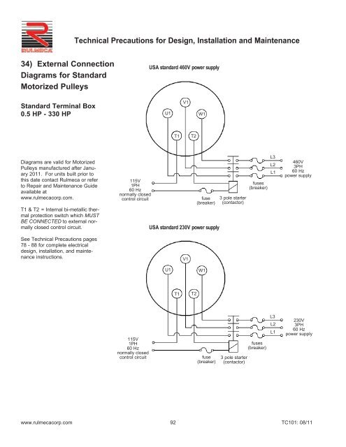
Technical Precautions for Design, Installation and Maintenance34) External <strong>Connection</strong><strong>Diagrams</strong> for StandardMotorized PulleysUSA standard 460V power supplyStandard Terminal Box0.5 HP - 330 HPU1V1W1T1T2<strong>Diagrams</strong> are valid for MotorizedPulleys manufactured after January2011. For units built prior tothis date contact Rulmeca or referto Repair and Maintenance Guideavailable atwww.rulmecacorp.com.T1 & T2 = Internal bi-metallic thermalprotection switch which MUSTBE CONNECTED to external normallyclosed control circuit.See Technical Precautions pages78 - 88 for complete electricaldesign, installation, and maintenanceinstructions.115V1PH60 Hznormally closedcontrol circuitfuse(breaker)USA standard 230V power supplyV13 pole starter(contactor)fuses(breaker)L3L2L1460V3PH60 Hzpower supplyU1W1T1T2115V1PH60 Hznormally closedcontrol circuitfuse(breaker)3 pole starter(contactor)fuses(breaker)L3L2L1230V3PH60 Hzpower supplywww.rulmecacorp.com 92TC101: 08/11
Technical Precautions for Design, Installation and Maintenance34) External <strong>Connection</strong><strong>Diagrams</strong> for StandardMotorized Pulleyswith Internal Brake460V60 HzUSA standard 460V power supply(with 207VDC brake)1 2 3 4 5 6brake rectifierterminationsStandard Terminal Box0.5 HP - 20 HPF1V1F2U1W1<strong>Diagrams</strong> are valid for MotorizedPulleys manufactured after January2011. For units built prior to thisdate contact Rulmeca or refer toRepair and Maintenance Guideavailable at www.rulmecacorp.com.T1 & T2 = Internal bi-metallic thermalprotection switch which MUSTBE CONNECTED to external normallyclosed control circuit.115V1PH60 Hznormally closedcontrol circuitT1T2fuse(breaker)3 pole starter(contactor)fuses(breaker)L3L2L1460V3PH60 Hzpower supplySee Technical Precautions pages78 - 88 for complete electricaldesign, installation, and maintenanceinstructions.Brake rectifier is shown with jumperacross terminals 3 and 4. Thisenables AC power supply to rectifierto stop and start brake. Brakeresponsiveness may be improvedby connecting an external switch toterminals 3 and 4.Internal electromagnetic brake isavailable in models 220M - 500M.230V60 HzUSA standard 230V power supply(with 104VDC brake)1 2 3 4 5 6U1F1V1F2W1brake rectifierterminationsT1T2115V1PH60 Hznormally closedcontrol circuitfuse(breaker)3 pole starter(contactor)fuses(breaker)L3L2L1230V3PH60 Hzpower supplywww.rulmecacorp.com 93TC101: 08/11
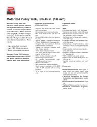
Technical Precautions for Design, Installation and Maintenance34) <strong>Connection</strong> <strong>Diagrams</strong>for Motorized PulleysModel <strong>138E</strong> - 400L in 3 phasePower Cord0.13 HP - 5.5 HPModel <strong>138E</strong> in 1 phasePower Cord0.13 HP - 0.75 HPPower cord wires are supplied withblack insulation and white numbers.Wire numbers are indicated on the diagram.T1 & T2 = Internal bi-metallic thermalprotection switch which MUST BECONNECTED to external normallyclosed control circuit.EB = electromagnetic brake460VAC3PH60 Hzpower supply115VAC1PH60 Hznormallyclosedcontrol circuitfuses(breaker)L1L2L33 pole starter(contactor)USA standard460V power supplyU1V1W13-Ph-MotorT1T21 2 3 4 5 gn/ye460VAC3PH60 Hzpowersupply115VAC1PH60 Hznormallyclosedcontrol circuitfuses(breaker)L1L2L3USA standard 460V power supply(with 207VDC brake)3 pole starter(contactor)460VAC60 HzU1V1W13-Ph-Motor (EB)T1T2B1B21 2 3 4 5 6 7 gn/ye1 2 3 4 5 6brake rectifierterminationsSee Technical Precautions pages78 - 88 for complete electrical design,installation, and maintenance instructions.Brake rectifier is shown with jumperacross terminals 3 and 4. This enablesAC power supply to rectifier to stopand start brake. Brake responsivenessmay be improved by connecting anexternal switch to terminals 3 and 4.For two speed motor details contactRulmeca.Internal electromagnetic brake is availablein models <strong>138E</strong> - 500M.VACpowersupplyVACnormallyclosedcontrolcircuitfuses(breaker)L1NSingle Phase power supply(clockwise rotation)2 pole starter(contactor)1-Ph-MotorZ1U1U2Z2T1T2Single Phase power supply(counterclockwise rotation)3 1 2 4 5 6 gn/yefuses(breaker)4 1 2 3 5 6 gn/yeL1VACpower NsupplyVACnormallyclosedcontrolcircuit2 pole starter(contactor)1-Ph-MotorZ2U1U2Z1B1B2T1T2www.rulmecacorp.com 94TC101: 08/11
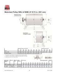
Technical Precautions for Design, Installation and Maintenance34) <strong>Connection</strong> <strong>Diagrams</strong>for Motorized PulleysUSA standard 460V power supplyModel <strong>138E</strong> in 3 phaseCompact Terminal Boxand WAGO-Clamp0.13 HP - 1.0 HP3-Ph-Motor Starrd ye bu gy gy bn bn bk bkTC/THSgn gnT1 & T2 = Internal bi-metallic thermalprotection switch which MUST BECONNECTED to external normallyclosed control circuit.See Technical Precautions pages 78- 88 for complete electrical design,installation, and maintenance instructions.460VAC3PH60 Hzpower supply115VAC1PH60 Hznormallyclosedcontrol circuitfuses(breaker)L1L2L33 pole starter(contactor)L1 L2 L3 1 2 3 4 5For two speed motor details contactRulmeca.RD = RedYE = YellowBK = BlackGY = GreyBU = BlueGN = GreenBN = BrownT1 & T2 = Thermal ProtectorUSA standard 230V power supplyTC/THS3-Ph-Motor Star/Starrd gy ye bn bu bk gy bn bk gn gn(1.) Pushdownclamp(2.) Push inwireAssembly instructions230VAC3PH60 Hzpower supply115VAC1PH60 Hznormallyclosedcontrol circuitfuses(breaker)L1L2L33 pole starter(contactor)L1 L2 L3 1 2 3 4 5www.rulmecacorp.com 95TC101: 08/11
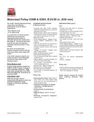
Technical Precautions for Design, Installation and Maintenance34) <strong>Connection</strong> <strong>Diagrams</strong>for Motorized PulleysModel <strong>138E</strong> in 1 phaseCompact Terminal Boxand WAGO-Clamp0.13 HP - 0.75 HPSingle Phase power supply (clockwise rotation)TC/THS1-Ph-Motorye bk bu rd gn gn<strong>Diagrams</strong> are valid for Motorized Pulleysmanufactured after January 2011.For units built prior to this date contactRulmeca or refer to Repair and MaintenanceGuide available at www.rulmecacorp.com.T1 & T2 = Internal bi-metallic thermalprotection switch which MUST BECONNECTED to external normallyclosed control circuit.VACpowersupplyVACnormallyclosedcontrol circuitL1Nfuses(breaker)2 pole starter(contactor)Y L1 L2 L3 T1 T2See Technical Precautions pages78 - 88 for complete electrical design,installation, and maintenance instructions.Single Phase power supply (counterclockwise rotation)For two speed motor details contactRulmeca.1-Ph-MotorTC/THSRD = RedYE = YellowBK = BlackGY = GreyBU = BlueGN = GreenBN = BrownT1 & T2 = Thermal Protector(1.) PushdownclampVACpowersupplyL1Nfuses(breaker)rd bk bu ye gn gnY L1 L2 L3 T1 T2(2.) Push inwireAssembly instructionsVACnormallyclosedcontrol circuit2 pole starter(contactor)www.rulmecacorp.com 96TC101: 08/11
Technical Precautions for Design, Installation and Maintenance34) External <strong>Connection</strong><strong>Diagrams</strong> for StandardMotorized Pulleyswith and withoutInternal BrakeNon-USA power supply without brakeV1U1W1Standard Terminal Box w/o brake0.5 HP - 330 HPT1T2Standard Terminal Box with brake0.5 HP - 20 HP<strong>Diagrams</strong> are valid for MotorizedPulleys manufactured after January2011. For units built prior to thisdate contact Rulmeca or refer toRepair and Maintenance Guideavailable at www.rulmecacorp.com.VAC1PHnormally closedcontrol circuitfuse(breaker)3 pole starter(contactor)fuses(breaker)L3L2L1VAC3PHpower supplyT1 & T2 = Internal bi-metallic thermalprotection switch which MUSTBE CONNECTED to external normallyclosed control circuit.See Technical Precautions pages78 - 88 for complete electricaldesign, installation, and maintenanceinstructions.VAC1PHNon-USA power supply with brake1 2 3 4 5 6brake rectifierterminationsBrake rectifier is shown with jumperacross terminals 3 and 4. Thisenables AC power supply to rectifierto stop and start brake. Brakeresponsiveness may be improvedby connecting an external switch toterminals 3 and 4.U1F1V1F2W1Internal electromagnetic brake isavailable in models 220M - 500M.T1T2VAC1PHnormally closedcontrol circuitfuse(breaker)3 pole starter(contactor)fuses(breaker)L3L2L1VAC3PHpower supplywww.rulmecacorp.com 97TC101: 08/11
Technical Precautions for Design, Installation and Maintenance34) External <strong>Connection</strong>Diagram for StandardMotorized Pulleys500H - <strong>1000HD</strong> with InternalAnti-condensationHeating Element<strong>Diagrams</strong> are valid for Motorized Pulleysmanufactured after January 2004. For unitsbuilt prior to this date contact Rulmeca orrefer to Repair and Maintenance Guide availableat www.rulmecacorp.com.USA standard 460V power supplyTerminals H1 & H2 for the anti-condensationheating element are live during MotorizedPulley stoppage.Terminals T1 & T2 for thermal protectionswitch which MUST BE CONNECTED toexternal normally closed control circuit.See Technical Precautions pages 78 - 88 forcomplete electrical design, installation, andmaintenance instructions.34) External <strong>Connection</strong>Diagram for StandardMotorized Pulleys500H - <strong>1000HD</strong> withTrickle Voltage HeatingAnti-condensation heating element must be connected insuch a way that it is turned off during motor operation.115V 1PH 60 Hznormally closed control circuitUSA standard 460V power supply460V 3PH 60 Hzpower supply<strong>Diagrams</strong> are valid for Motorized Pulleysmanufactured after January 2004. Forunits built prior to this date contact Rulmecaor refer to Repair and MaintenanceGuide available at www.rulmecacorp.com.T1 & T2 = Internal bi-metallic thermal protectionswitch which MUST BE CON-NECTED to external normally closed controlcircuit.See Technical Precautions pages 78 - 88for complete electrical design, installation,and maintenance instructions.Note: The time delay for (TR) shouldbe between 10 and 180 seconds.www.rulmecacorp.com98TC101: 08/11