Corken Z series spare parts - Acme Fluid Handling
Corken Z series spare parts - Acme Fluid Handling
Corken Z series spare parts - Acme Fluid Handling

Create successful ePaper yourself
Turn your PDF publications into a flip-book with our unique Google optimized e-Paper software.
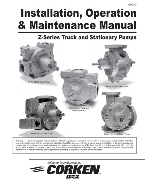
ID105GInstallation, Operation& Maintenance ManualZ-Series Truck and Stationary PumpsModel Z2000 Truck PumpModel Z3200 Truck PumpModel Z3500 Truck andStationary PumpModel Z4200 Truck PumpModel Z4500 Stationary PumpWarning: (1) Periodic inspection and maintenance of <strong>Corken</strong> products is essential. (2) Inspection, maintenance and installation of <strong>Corken</strong>products must be made only by experienced, trained and qualified personnel. (3) Maintenance, use and installation of <strong>Corken</strong> products mustcomply with <strong>Corken</strong> instructions, applicable laws and safety standards (such as NFPA Pamphlet 58 for LP-Gas and ANSI K61.1-1972 forAnhydrous Ammonia). (4) Transfer of toxic, dangerous, flammable or explosive substances using <strong>Corken</strong> products is at user’s risk and equipmentshould be operated only by qualified personnel according to applicable laws and safety standards.
Table of ContentsApplicable Notice of ATEX Conformity ............................................................................................................................ 4Principles of the Z-Series Coro-Vane ® Pump .................................................................................................................. 5Exclusive Features of Your Z-Series Coro-Vane ® Pump ................................................................................................. 5Installation of the Z-Series Coro-Vane ® Truck Pumps ..................................................................................................... 5Outlet Piping Should Include the Following ................................................................................................................. 6Bypass System ............................................................................................................................................................ 6Power Take-off Drive Systems ..................................................................................................................................... 6Hydraulic Drive Systems ................................................................................................................................................. 7Operation of Your Z-Series Coro-Vane ® Truck Pump....................................................................................................... 7How to Transfer From the Truck Tank at Full Capacity..................................................................................................... 7Installation of Your <strong>Corken</strong> Z-Series Coro-Vane ® Stationary Pump................................................................................. 8The Inlet Piping Should Include the Following ............................................................................................................. 8The Outlet Piping Should Include the Following .......................................................................................................... 8The Bypass System Must Include the Following ......................................................................................................... 9A Vapor Equalizing System Should Include the Following ........................................................................................... 9Driver Installation ......................................................................................................................................................... 9Operation of Your Z-Series Stationary Coro-Vane ® Pump............................................................................................... 9Maintenance of Your Z-Series Coro-Vane ® Truck Pump System ................................................................................... 11Lubrication ................................................................................................................................................................. 11Pump Maintenance Schedule .................................................................................................................................... 11Preventive Maintenance Program .............................................................................................................................. 12Z-Series Coro Vane ® Seal Replacement Instructions ................................................................................................... 13Repair/Re-build Kits ...................................................................................................................................................... 15Pump Assembly Instructions For Z-Series Truck Pumps .............................................................................................. 16Appendix AModel Number and Identification Code ..................................................................................................................... 17Appendix BFeatures, Benefits, and Operations and Material Specifications ............................................................................... 19Appendix CPerformance Curves and Charts ............................................................................................................................... 20Appendix DOutline Dimensions .................................................................................................................................................... 26Appendix EParts Details............................................................................................................................................................... 36Appendix FV-Belt Selection for Stationary Coro-Vane ® Pumps ................................................................................................... 41Appendix GTroubleshooting Guide ............................................................................................................................................... 42Appendix HStorage of the Z-Series Coro-Vane ® Truck Pumps .................................................................................................... 43Appendix IHydraulic Motor Specifications................................................................................................................................... 433
3. Check V-belt drive or direct drive coupling alignment.Misalignment will cause accelerated wear of the drivesystem, motor bearings and pump.4. Check motor for proper wiring.5. Review complete system to make certain the functionof every valve and piece of equipment is clearlyunderstood. Everyone operating this system must beproperly trained in normal operating procedures andemergency procedures in event of a malfunction.6. Close all hose valves.7. Slowly open the storage tank bottom shut-off valve(suction line to the pump). Immediately check thesystem for leaks.8. Open any shut-off valves between the bypass valve andthe storage tank.9. Make a note of all pressure gauge readings, especiallythe pressure gauge located at the discharge of thepump. Start the pump and circulate the liquid throughthe bypass system back to the storage tank.10. Verify the proper pump rotation direction. There is anarrow cast in the pump case.11. An ammeter may be used by adjusting the bypassvalve until the ammeter indicates the full load motoramperage rating shown on the motor nameplate ormaximum rated differential, whichever comes first.Permit the pump to circulate liquid for half an hour ormore. If the motor overload protection device stopsthe motor in this period the bypass valve setting is toohigh and should be readjusted until the motor will runfor half an hour. After a satisfactory setting is achieved,“seal” the valve adjusting stem to prevent tamperingwith the adjustment. See Important Instructions (IH102)and Installation, Operation and Maintenance (IOM)Manual (IH106) for more details on the use of the<strong>Corken</strong> bypass valves.12. Your pump has an internal relief valve, it must be set higherthan the external bypass setting. The internal relief valveis factory preset.13. After initial operation, re-check the strainer screen.10
Z-Series Coro-Vane ® Seal Replacement InstructionsPlease Note: The photos listed below contain a Z2000;however, all Z-Series pumps use the same procedures forseal replacement.To determine the <strong>parts</strong> needed for repair, refer toAppendix A—Model Number and Identification Code, andAppendix E—Parts Details.CAUTION! BLEED ALL PRESSURE FROM THEPUMP AND PIPING BEFORE STARTING TOINSTALL YOUR SEAL ASSEMBLY.CleanlinessEven the smallest amount of dirt on your new seal can cause earlyfailure. Keep all <strong>parts</strong>, tools and your hands clean while installingthe seal. Never touch the smooth lapped faces of the carbon rotoror seal seat. For LP-Gas, anhydrous ammonia and similar liquids,you are trying to seal a fluid that is 5 to 10 times thinner than water!Your new seal needs every chance it can get, so keep it clean.WorkmanshipYour <strong>Corken</strong> pump is a precision piece of equipment withvery close clearances. Treat it as such. Never use forceduring assembly or disassembly (see steps 1 through 10).Step 1Depressurize and open the pumpStep 3Seal seat and grease seal installationLoosen the head bolts and remove one head with thebearing cap attached, while holding in on the shaft.Step 2Seal seat and grease seal removalNOTE: The above photo is of a cutaway for better details.Turnthe head over and install the new grease seal face down bypressing into the bore behind the main bearing. This can bestbe accomplished using the old seal seat with the O-ringremoved. Apply a generous amount of light oil to the new sealseat. Using the protective disc, gently press seal into place.Step 4Seal retainer and carbon removalNOTE: The above photo is of a cutaway for better details.Remove the head O-ring and place head on the workbench asshown. Lightly tap the seal out of the head with a long screwdriverby reaching through the bearing cap opening. Inspect the innerlip seal and remove, if necessary, using same process.Remove the old seal assembly from the pump shaft while pressingagainst the sideplate. This will allow the seal retainer assembly tobe removed without pulling the rotor-shaft out of the pump.13
Z-Series Coro-Vane ® Seal Replacement InstructionsStep 5Seal retainer and carbon installationStep 7Completing installationClean the pump and apply a generous amount of light oil.Install the new seal assembly by aligning the seal retainerslot with the seal drive pin on the shaft.Step 6Mechanical seal installationTorque the head bolts in a crossing pattern. There is noneed to disassemble or re-shim the bearing caps. Repeatall of the above steps when replacing the seal assembly onthe opposite side.Step 8Lubrication & re-pressurizingNote: Both sides of the pump are identical; duplicateprocedure to change the seal on the opposite side.LubricationRegrease the bearing after thoroughly cleaning the greaseopening and fittings. If dirt is forced into the bearings, earlyfailure will result.Special relief fittings have been provided to help preventover-greasing the bearings. Excessive grease may drip outafter lubrication. Over-greasing can damage the pumpbearings and cause seal leaks.Install the new case O-ring onto the head.Apply a generous amount of light oil to each seal face andcarefully install the head assembly over the pump shaft.Use only a recommended ball bearing grease. If you use ahand grease gun, put the grease in slowly and stop as soonas the relief fitting opens.Grease the U-joints and the spline of the drive shaft whengreasing the pump.Re-pressurizeNOTE: FOR BEST RESULTS, SLOWLY PRESSURIZEWITH VAPOR PRESSURE.Please note: If you pressurize with liquid, it will sometimesrefrigerate even though it enters the pump slowly. As a result,the seal elastomers will not seal properly thereby causingthem to leak.14
Repair/Re-build KitsZ2000, ZH2000, ZX2000, ZXH2000 Repair Kit 3193-X12-224A O-ring, Buna-N 12-231A O-ring, Buna-N 22754-X Roller bearing 24262-X Vane driver 34428 Vane 64431-XA2 Seal assembly 24432 Thrust bearing 24435 Thrust bearing mounting ring 24439 Bearing cap shim (0.002) 84439-1 Bearing cap shim (0.010) 24439-2 Bearing cap shim (0.020) 24441 Grease seal 22270 Shaft key 1Z4200, ZH4200, Z4500 Repair Kit 3197-X12-231A O-ring, Buna-N 12-234A O-ring, Buna-N 24460-X Roller bearing 24449-X Vane driver 54448 Vane 64464-XA2 Seal assembly 24453 Thrust bearing 24454 Thrust bearing mounting ring 24458 Bearing cap shim (0.002) 84458-1 Bearing cap shim (0.010) 24458-2 Bearing cap shim (0.020) 24463 Grease seal 24459 Shaft key 1Z3200, ZH3200 Repair Kit 3195-X12-224A O-ring, Buna-N 12-234A O-ring, Buna-N 22754-X Roller bearing 24262-X Vane driver 34232 Vane 64431-XA2 Seal assembly 24432 Thrust bearing 24435 Thrust bearing mounting ring 24439 Bearing cap shim (0.002) 84439-1 Bearing cap shim (0.010) 24439-2 Bearing cap shim (0.020) 24441 Grease seal 22270 Shaft key 1Z3500 Repair Kit 3195-X22-228A O-ring, Buna-N 22754-X Roller bearing 25554-X Vane driver 33936 Vane 64431-XA2 Seal assembly 24432 Thrust bearing 24435 Thrust bearing mounting ring 24439 Bearing cap shim (0.002) 84439-1 Bearing cap shim (0.010) 24439-2 Bearing cap shim (0.020) 24441 Grease seal 22270 Shaft key 1Z2000, ZH2000, ZX2000, ZXH2000 Re-Build Kit 3194-X1Includes all items in the Repair Kit plus the following:4414 Cam 14427 Sideplate 2Z3200, ZH3200 Re-Build Kit 3196-X1Includes all items in the Repair Kit plus the following:4242 Cam 14231 Sideplate 2Z3500 Re-Build Kit 3196-X2Includes all items in the Repair Kit plus the following:5539 Cam 13935 Sideplate 2Z4200, ZH4200, Z4500 Re-Build Kit 3198-X1Includes all items in the Repair Kit plus the following:4443 Cam 14446 Sideplate 2All repair and re-build kits have Buna-N O-rings which are suitable forboth LPG and NH 3applications.15
Pump Assembly Instructions For Z-Series Truck Pumps1. Place the pump head on a clean work surface with thebolting flange down.2. Press the inner grease seal in through the main bearingcavity until flush with the bottom of the bore. Seal lips mustbe oriented down as shown in each <strong>parts</strong> detail drawing.3. Press the main bearing into the head and install theretainer ring.4. Install the relief fitting into 1/8 in. NPT threaded holeand turn the head over.15. Turn the pump over and remove the first head.16. Install the seal retainer assembly and carbon asoutlined in step 13 above.17. Bolt head to case as described in step 14 above. Ensurethe rotor shaft turns freely in either direction.18. Slide the bearing race mounting ring onto one end ofthe shaft until contact with the main bearing inner race.Mount the thrust bearing assembly onto the bearingrace mounting ring and install the bearing cap.5. After lubricating the mechanical seal seat with light oil,press the seal seat into the head using your fingers. Makesure the seal seat is fully seated and the shiny side facesup. Apply a generous amount of light oil to the seal seatto remove any remaining debris and fingerprints. Installthe case O-ring around the pilot OD of the head.6. Press the outer grease seals into each of thebearing caps.7. Press the spring pins into each of the cam key holes.8. Install the cam key into the pump case. Slide the caminto the pump case aligning the long inlet slots to theinlet portion of the case.9. Install one sideplate and bolt one head into place withtwo bolts.10. Turn the pump onto the assembled head. Ensure thereis enough room to allow the shaft to extend through theassembled head by six inches.19. Lightly tighten the bearing cap with two opposed boltsuntil the rotor shaft cannot be freely turned. Measurethe gap between the head and bearing cap at four pointsaround the bearing cap. Adjustment may be necessaryto contain the gap within .001 inch. Round up theaverage measurement to the nearest even number. Thisis the measured amount of bearing cap shims. Refer to<strong>parts</strong> pages for shim measurements.20. Remove the two bearing cap bolts and install themeasured amount of shims plus .006 inch. Install thefour bearing cap bolts and torque in a crossing pattern.21. Install the remaining bearing race mounting ringand thrust bearing assembly on the opposite sideof the pump.22. Perform step 19 again on the opposite side and installthe measured shims plus .002 inch. Install the fourbearing cap bolts and torque in a crossing pattern.23. Install the shaft key and ensure shaft rotates smoothly.11. While holding the rotor-shaft vertical, install the vanedrivers. Vertically install the rotor-shaft into the unit. Slidethe vanes into each rotor slot ensuring the rounded tipcontacts the cam and the vane slots face into the directionof rotation as shown in each <strong>parts</strong> detail drawing.12. Install the remaining sideplate.13. Lubricate the pump shaft and seal carbon with light oil.Install the seal retainer assembly by aligning the retainerslot onto the seal alignment pin. Carefully press the sealcarbon into the retainer assembly with the polished faceoriented outward by aligning the carbon notches to theretainer pins. Again, apply a generous amount of light oilto remove any remaining debris and fingerprints.14. Carefully install the head over the pump shaft and sealassembly and torque the bolts in accordance with theappropriate bolt torque pattern drawing. This patternensures even bolting of the head into the case withoutdeforming the cam inlet port. This is done by boltingthose bolts over the solid portion of the cam port.16
Appendix A—Z-Series Truck Pumps Model Number and Identification CodeBase Model Z2000/ZH2000 ZX2000/ZXH2000 Z/ZH3200 Z/ZH4200Inlet 2" NPT 2" NPT 3" ANSI 4" ANSIOutlet 2" NPT 2" NPT 2" ell Dual 2" NPTAuxillary Inlet None None 2" NPT 2" NPTInternal Relief 150 psi 175 psi 150 psi 150 psiWeight Bare 100 100 140 275Pump lb (kg) (45) (45) (64) (125)Model NumberBase X X X X X XVaneType6 Vanes withVane DriversStandardHVanes GCB-50 Standard GO-ring Buna-N Standard AMaterial Neoprene ®1 No charge option B1Neoprene ® is a registered trademark of the DuPont company.Flange Options WF=Slip-on weld flange ell = Elbow All ANSI flanges are 300# • indicates available flange connectionsInlet FlangeStandard2" NPT • • E3" ANSI • P4" ANSI • SExtra CostOptions2" WF • • FOutlet FlangeStandard2" NPT • • • E2" NPT ell • GNo Cost 1-1/2" NPT • COptions 2" NPT • E1-1/2" WF • DExtra Cost2" WF • • • • FOptions2" NPT ell • • GAuxillary Flange2" NPT • • EStandard None • • U1-1/2" NPT • CNo Cost Blind Flange • • TOptions 1-1/2" WF • DExtra Cost 2" WF • • FOptions 2" NPT ell • GPart Number Test—Options3000-X1 Hydrostatic test17
Appendix A—Z-Series Stationary Pump Model Number andIdentification CodeBase Model Z3500 Z4500Inlet 3" NPT (Standard) 4" 300# ANSIOutlet 3" NPT Elongated (Standard) 3" 300# ANSIWeight—bare 160 265pump lb (kg) (73) (120)Model NumberBase X X X X XVaneType6 Vanes withVane DriversStandardHVanes GCB-50 Standard GO-ring Buna-N Standard AMaterial Neoprene ®1 No charge option BFlange Options WF=Slip-on weld flange All ANSI flanges are 300# • indicates available flange connectionsInlet FlangeStandard4" ANSI • S3" NPT • MNo CostOption4" NPT • QExtra Cost 3" WF • NOption 4" WF • ROutlet FlangeStandard3" ANSI • P3" NPT Elongated • SExtra Cost 3" WF Elongated • TOptionMounting OptionsDescription Model Part Number Maximum Driver (hp) Ship Weight (mounting only) lbMounting set up for V-belt drive. Includes steel baseplate,adjustable motor slid base, V-belt drive andZ4500 103-15- 284T 630enclosed beltguardZ3500 103-10- 284T 560Part Number Test—Options3000-X1 Hydrostatic test1Neoprene ® is a registered trademark of the DuPont company.18
Appendix B—SpecificationsEquipment Type & OptionsTruck sliding vane pumpMultiple connection optionsOptional auxiliary inletFeatures & BenefitsSliding vane type:Heavy duty bearings:Single mechanical seal:Built in relief valve (NPT models only):Pressure gauge connections:Reversible side plates:Operating SpecificationsPositive displacement pumpLong bearing lifeVery easy seal replacement and maintenanceFactory pre-set— added protectionSuction and discharge to reduce piping needsLonger service lifeRPM range: 420–800 RPM Max. differential pressure:125 psid (8.6 bar d)for Z/ZH2000, Z/ZH3200, Z/ZH4200, and Z4500Max. working pressure: 400 psig (28.6 bar)150 psid (10.3 bar d) for ZX/ZXH2000 and Z3500Temperature range: -25°F– 225°F (-32°C –107°C) Flow range: 41–400 gpm (155–1,514 L/min)Internal relief valve: YesMaterial SpecificationsPart Model Standard Material Optional MaterialCase, head, rotor, relief- All Ductile iron ASTM A536valve cap, bearing capCam All Gray iron ASTM A48, Class 50Sideplate All Gray iron ASTM A48, Class 30Welding flange All SteelSeal seat All Gray iron Stainless steel & Ni-ResistSeal metal <strong>parts</strong> Z/ZH/ZX/ZXH2000,Z/ZH3200 SteelZ3500, Z/ZH4200, Z4500Shaft All 8620 steelVanes and vane drivers All Advanced polymersZ/ZH3200Steel, cadmium platedRelief valve spring Z/ZH/ZX/ZXH2000, Z3500,Z/ZH4200, Z4500Stainless steelZ/ZH3200, Z3500SteelRelief valveZ/ZH/ZX/ZXH2000,Z/ZH4200, Z4500Stainless steelBearing All SteelThrust bearing All SteelO-rings All Buna-N PTFE, Viton ® , Neoprene ®1Retainer rings All Steel1Viton ® and Neoprene ® are registered trademarks of the DuPont company.ApplicationsPropane bulk transferNH 3nurse tanksLPG cylindersAuto-fuel pumpingCarousel cylinder filling19
Appendix C—Z2000, ZH2000, ZX2000, and ZXH2000Performance Curves9080750 RPMCapacity (gpm) 17060650 RPM600 RPM50500 RPM4030255075100125150Differential Pressure (psid)1The chart shows approximate delivery rates as seen in vapor equalized propane systems at 70°F (21°C) with no pressure loss in pump suction piping.The following will cause increased vaporization of the liquid in the pump suction, adversely affecting the delivery:1. Restrictions in the suction piping such as internal valves, excess flow valves, elbows, etc.2. Restriction or lack of a vapor return line3. Temperatures below 70°F (21°C)This loss of delivery is not caused by the pump but is a result of the natural thermodynamic properties of liquefied petroleum gases. See the “GUIDETO CORKEN LIQUEFIED GAS TRANSFER EQUIPMENT” (CP226) for additional information.20
Appendix C—Z3200 and ZH3200 Performance Curves120110750 RPM100Capacity (gpm) 19080650 RPM600 RPM70500 RPM6050255075100125Differential Pressure (psid)1The chart shows approximate delivery rates as seen in vapor equalized propane systems at 70°F (21°C) with no pressure loss in pump suction piping.The following will cause increased vaporization of the liquid in the pump suction, adversely affecting the delivery:1. Restrictions in the suction piping such as internal valves, excess flow valves, elbows, etc.2. Restriction or lack of a vapor return line3. Temperatures below 70°F (21°C)This loss of delivery is not caused by the pump but is a result of the natural thermodynamic properties of liquefied petroleum gases. See the “GUIDETO CORKEN LIQUEFIED GAS TRANSFER EQUIPMENT” (CP226) for additional information.21
Appendix C—Z4200 and ZH4200 Performance Curves400380360750 RPM340Capacity (gpm) 1320300280260650 RPM600 RPM240220200500 RPM180255075100125Differential Pressure (psid)1The chart shows approximate delivery rates as seen in vapor equalized propane systems at 70°F (21°C) with no pressure loss in pump suction piping.The following will cause increased vaporization of the liquid in the pump suction, adversely affecting the delivery:1. Restrictions in the suction piping such as internal valves, excess flow valves, elbows, etc.2. Restriction or lack of a vapor return line3. Temperatures below 70°F (21°C)This loss of delivery is not caused by the pump but is a result of the natural thermodynamic properties of liquefied petroleum gases. See the “GUIDETO CORKEN LIQUEFIED GAS TRANSFER EQUIPMENT” (CP226) for additional information.22
Appendix C—Performance ChartsZ2000, ZH2000, ZX2000, and ZXH2000 Coro-Vane ® Truck PumpsPump Differential Approximate Delivery Brake hp Pump TorqueSpeed Pressure of Propane 1 Required RequiredRPM psid (kPa) gpm (L/min) bhp (kW) ft•lb (N•M)750 50 (345) 82 (309) 2.9 (2.2) 20.4 (27.7)750 100 (689) 77 (291) 5.8 (4.3) 40.8 (55.3)750 150 2 (1,034) 75 (284) 8.9 (6.63) 62.2 (84.3)650 50 (345) 69 (261) 2.5 (1.9) 20.4 (27.7)650 100 (689) 64 (242) 5.1 (3.8) 40.8 (55.3)650 150 2 (1,034) 63 (238) 7.7 (5.7) 62.2 (84.3)600 50 (345) 63 (238) 2.3 (1.7) 20.4 (27.7)600 100 (689) 58 (219) 4.6 (3.5) 40.8 (55.3)600 150 2 (1,034) 56 (212) 7.1 (5.3) 62.2 (84.3)500 50 (345) 52 (197) 1.9 (1.4) 20.4 (27.7)500 100 (689) 46 (174) 3.9 (2.9) 40.8 (55.3)500 150 2 (1,034) 44 (166) 5.9 (4.4) 62.2 (84.3)Z3200 and ZH3200 Coro-Vane ® Truck PumpsPump Differential Approximate Delivery Brake hp Pump TorqueSpeed Pressure of Propane 1 Required RequiredRPM psid (kPa) gpm (L/min) bhp (kW) ft•lb (N•M)750 50 (345) 112 (424) 6.2 (4.6) 43.4 (58.9)750 100 (689) 99 (375) 9.9 (7.4) 69.3 (94.0)650 50 (345) 95 (360) 5.2 (3.9) 42.0 (57.0)650 100 (689) 84 (318) 8.2 (6.1) 66.3 (89.9)600 50 (345) 86 (326) 5.0 (3.7) 41.3 (56.0)600 100 (689) 76 (288) 7.8 (5.9) 64.8 (87.9)500 50 (345) 70 (265) 3.8 (2.8) 39.9 (54.1)500 100 (689) 62 (235) 5.8 (4.3) 60.9 (82.6)Z4200, ZH4200, and Z4500 Coro-Vane ® Truck PumpsPump Differential Approximate Delivery Brake hp Pump TorqueSpeed Pressure of Propane 1 Required RequiredRPM psid (kPa) gpm (L/min) bhp (kW) ft•lb (N•M)750 50 (345) 369 (1,397) 12.5 (9.3) 87 (118.0)750 100 (689) 325 (1,230) 25.1 (18.6) 175 (237.3)650 50 (345) 316 (1,196) 10.8 (8.0) 87 (118.0)650 100 (689) 278 (1,052) 21.7 (16.1) 175 (237.3)600 50 (345) 289 (1,094) 9.9 (7.3) 87 (118.0)600 100 (689) 254 (961) 20.0 (14.8) 175 (237.3)500 50 (345) 236 (893) 8.3 (6.2) 87 (118.0)500 100 (689) 208 (787) 16.7 (12.4) 175 (237.3)1Delivery times are approximate—see note on page 22 for further explanation.2Applies to ZX/ZXH2000 models only.23
Appendix C—Performance CurvesZ350024
Appendix C—Performance CurvesZ450025
INTERNAL RELIEF VALVESET AT 150 P.S.I.Appendix D—Outline Dimensions for Model Z200016(40.61)1/4" x 1-9/16" square key2-1/8(5.40)NOT FOR RECIRCULATINGINSTALLER TO PROVIDESEPARATE BY-PASS VALVESET AT 125 P.S.I. MAXIMUMCORKEN, INC.A Unit Of IDEX Corp.2-1/8(5.40)1-1/8(2.85)3-1/4(8.25)Internal Relief ValveOutlet:2" NPT1/4" NPT5-15/16(15.08)4-9/16(11.59)2-3/8(6.03)OUTLET3/4(1.92)CORKEN5-1/2(13.97)1/4" NPTInlet:2" NPTINLETNEKROC4-1/2(11.43)Four 7/16 (1.11)diameter holes2-1/2(6.35)6-1/2(16.51)262-1/2(6.35)All dimensions are in inches (centimeters).
INTERNAL RELIEF VALVESET AT 150 P.S.I.NOT FOR RECIRCULATINGINSTALLER TO PROVIDESEPARATE BY-PASS VALVESET AT 125 P.S.I. MAXIMUMCORKEN, INC.A Unit Of IDEX Corp.Appendix D—Outline Dimensions for Model Z32001-1/8(2.86)10-15/16(27.78)4-15/16(12.47)8-3/4(22.23)17-1/2(44.43)1/4"NPT3-7/16(8.73)6-3/4(17.14)2" NPT auxillary inlet14-15/16(37.94)5(12.70)1/4" NPT2" NPTdischargeInternalreliefvalve1-5/8 (4.13)5-11/32(13.57)3-7/8(9.84)8-1/4 D(20.95)1/4" square keyway3" 300 lb ANSI flange inlet6-5/8 BC(16.83)1-1/8(2.86)2-7/16(6.24)Eight 7/8" (2.22) diameter holesAll dimensions are in inches (centimeters).27
Appendix D—Outline Dimensions for Model Z3500All dimensions are in inches (centimeters).28
Appendix D—Outline Dimensions for Model Z42001-3/16(3.01)Internal relief valveINLET2" NPTauxillaryinletC O RKEN1/4" NPT8(20.32)13-13/16(35.08)2-5/8(6.67)OUTLET3-1/4(8.26)NEKC O R1/4" NPT7(17.78)7-3/4(19.69)16-31/32(43.08)10-1/8 D(25.72)19-1/2(49.53)7-7/8 BC(20.00)Inlet:4" 300 lb ANSIflange2-1/8(5.40)1-1/4 (3.18)1-1/4(3.17)5/16" square key 5/16" square keyEight 7/8 (2.22)diameter holesOutlet: 2" NPTOutlet: 2" NPT4(10.16)4(10.16)All dimensions are in inches (centimeters).29
Appendix D—Outline Dimensions for Model Z45008-Ø .875 (2.2)on a 6-5/8" B.C.Outlet3" R.F. 300#ANSI flange8.469(21.5)1.875(4.8)Inlet4" R.F. 300#ANSI flange5/16"square key10.75(27.3)1.0(2.5)6.5(16.5)21.121(53.6)2.875(7.3)2.875(7.3)8-Ø .875 (2.2)on a 7-7/8" B.C.4-5/8 (1.587)mounting holes4.688(11.9)4.688(11.9)6.125(15.6)All dimensions are in inches (centimeters).30
INTERNAL RELIEF VALVESET AT 150 P.S.I.NOT FOR RECIRCULATINGSET AT 125 P.S.I. MAXIMUMCORKEN, INC.A Unit Of IDEX Corp.4248Appendix D—Outline Dimensions for Model ZH2000Hydraulic drive adapter assemblyINSTALLER TO PROVIDESEPARATE BY-PASS VALVE1/4" square keyway2-1/8(5.40)Char-Lynn Hydraulics, Inc.A Division of EATON6.2 Cubic Inch / RevDisc Valve Hydraulic MotorModel No. 104-10021-1/8 D(2.85)Hydraulic motor17-11/16(44.90)10-1/2(26.63)3-1/4(8.25)13/16(2.06)8(20.30)5-15/16(15.08)1/4" NPT4-9/16(11.59)2-3/8(6.03)Outlet: 2" NPTInternalreliefvalveCORKENOUTLET5-1/2(13.97)1/4" NPT3/4(1.92)Inlet: 2" NPTINLETNEKROC4-1/2(11.43)2-1/2(6.35)6-1/2(16.51)2-1/2(6.35)All dimensions are in inches (centimeters).31
INTERNAL RELIEF VALVESET AT 150 P.S.I.NOT FOR RECIRCULATINGINSTALLER TO PROVIDESEPARATE BY-PASS VALVESET AT 125 P.S.I. MAXIMUMCORKEN, INC.A Unit Of IDEX Corp.Appendix D—Outline Dimensions for Model ZH320018-1/8 (46.02)10-15/16 (27.75)8-3/4 (22.22)Char-Lynn Hydraulics, Inc.A Division of EATON6.2 Cubic Inch / RevDisc Valve Hydraulic MotorModel No. 104-1002Hydraulic motorHydraulic driveadapter assembly3-7/8(9.84)6-5/8 D B.C.(16.83)8-1/4D(20.96)2-7/16(6.24)1-1/8 (2.86)1/4" square keyway3" 300 lb ANSI flange inletEight 8-7/8 (2.22)diameter holes10-15/16 (27.78)4-15/16 (12.47)1-1/8(2.87)3-7/15(8.73)1/4" NPT6-3/4(17.15)14-15/16(37.94)Internal relief valve5(12.70)1/4" NPT2" NPTdischarge1-5/8 (4.13)5-5/16(13.57)All dimensions are in inches (centimeters).32
MODELSERIALNO.CORKEN,INC. A Unit Of IDEX Corp.OKLAHOMA CITY,OKLAHOMA MADE IN U.S.A.POWER OPERATED PUMP FOR LPG OR ANHYDROUS NHREAD CORKEN INSTRUCTION MANUAL BEFORE OPERATINGLISTED 656LPAT. NOS. 3,072,066 AND 3,392,677RAppendix D—Outline Dimensions for Model ZH420019-9/16(49.69)12-3/8(31.43)9-3/4(24.77)Char-Lynn Hydraulics, Inc.A Division of EATON6.2 Cubic Inch / RevDisc Valve Hydraulic MotorModel No. 104-1002CORO-VANEHydraulic motorHydraulic driveadapter assemblyInlet: 4" 300 lbANSI flange10-1/8 D(25.72)4(10.16)4(10.16)7-7/8 B.C.(20.00)2-1/8(5.40)1-1/4 (3.18)5/16" square keywayEight 7/8 (2.22)diameter holesOutlet: 2" NPTOutlet: 2" NPTInternal relief valve1-3/16(3.01)1/4" NPTINLET2" NPTauxillaryinlet8(20.32)CORKEN2-5/8(6.67)3-1/4(8.26)OUTLETNEKROC13-13/16(35.08)1/4" NPT7-3/4 (19.69)7 (17.78)16-31/32 (43.08)All dimensions are in inches (centimeters).33
Appendix D—Outline Dimensions for Z3500–103 MountingAll dimensions are in inches (centimeters).34
Appendix D—Outline Dimensions for Z4500–103 MountingAll dimensions are in inches (centimeters).35
Appendix E—Parts Details for Models Z/ZH/ZX/ZXH200037 (45 ft•lb)341436 (25 ft•lb)Outlet36 (25 ft•lb)35 (15 ft•lb)1436 (25 ft•lb)Inlet37 (45 ft•lb)O-ring CodeD Viton ®1CAUTION: Always relieve pressure in the unit before attemptingany repairs.E Teflon ®1 Note: Hydraulic motor is not shown.A Buna-NSee page 15 for repair/re-build kits.B Neoprene ®136 (25 ft•lb)Ref.no. Part no. Description Qty.1. 4413 Case 12. 4414 Cam 13. 4416 Head 24. 4417 Bearing cap 25. 1174-3 Relief valve cap 16. 4282 Shim (Z2000, ZH2000) 1Shim (ZX2000, ZXH2000) 37. 4424 Cam key 18. 4425 Relief valve 19. 4426 Relief valve spring (Z2000, ZH2000) 11240 Relief valve spring (ZX2000, ZXH2000) 110. 4427 Sideplate 211. 4428 Vane 2 612. 4262-X Vane driver 313. 4430-X2R Rotor—shaft assembly 114. 4431-X_2 Mechanical seal assembly 4 215. 4432 Thrust bearing assembly 216. 4435 Bearing race mounting ring 217. 4438 Grease seal 218. 4439 Bearing cap shim (.002) red As4439-1 Bearing cap shim (.010) brown req.4439-2 Bearing cap shim (.020) yellow19. 2754-X Bearing 21Registered trademarks of the DuPont company.2Slots in vanes must face TOWARDS the direction of rotation.Ref.No. Part No. Description Qty.20. 3253 Cam key pin 221. 2760-244 Retainer ring 222. 4441 Grease seal 223. 2270 Shaft key—1/4" x 1-9/16" 224. 4479-2 Flange–2" NPT 3 225. 2649 Nameplate 126. 4248 Relief valve nameplate 1(Z2000, ZH2000)4248-1 Relief valve nameplate 1(ZX2000, ZXH2000)27. 1359 Lubrication instruction plate 228. 1343 1/8" NPT relief fitting 429. 2158 1/8" NPT grease zerk 230. 2159 Lubricap 231. 3442 1/4" NPT pipe plug 232. 2-231_ O-ring—flange 4 233. 2-224_ O-ring—relief valve cap 4 134. 2-261_ O-ring—case 4 235. 7001-031-NC125A Bolt—hexagon head 436. 7001-037-NC150A Bolt—hexagon head 1637. 7001-043-NC125A Bolt—hexagon head 1638. 7012-006-SF025E Screw 839. 7206-037A Lockwasher 83Optional: 4479-2S 2" welded.4_ denotes O-ring code. See chart above.36
Appendix E—Parts Details for Models Z/ZH320028 (60 ft•lb)2212425 (25 ft•lb)Inlet429 (15 ft•lb)28 (60 ft•lb)O-ring CodeA Buna-NB Neoprene ®1D Viton ®1E Teflon ®1Outlet(25 ft•lb)Note: Hydraulic motor is not shown.See page 15 for repair/re-build kits.CAUTION: Always relieve pressure in the unit before attempting any repairs.Ref.No. Part No. Description Qty1. 4495-X2R Rotor shaft assembly 12. 4242 Cam 13. 4232 Vane 5 64. 4231 Sideplate 25. 4488 Head 26. 4239 Case 17. 4417 Bearing cap 28. 4438 Grease seal 29. 4435 Mounting ring 210. 4439 Bearing shim (.002) red As4439-1 Bearing shim (.010) brown req.4439-2 Bearing shim (.020) yellow11. 2270 Shaft key 212. 4431-X_2 Mech. seal assembly 4 213. 2754 Bearing outer race 214. 4432 Thrust bearing assembly 215. 2760-244 Retainer ring 216. 1174-2 Relief valve cap 117. 1359 Lubrication instruction plate 218. 4441 Grease seal 219. 7012-006SF019E Screw 820. — Not shown –Ref.No. Part No. Description Qty21. — Not shown –22. 2-262_ O-ring—case 4 223. 2-224_ O-ring—relief valve cap 4 124. 1240 Relief valve spring 125. 7001-037NC150A Bolt—3/8-16 x 1-1/2" hex head 1626. 2158 1/8" NPT grease zerk 227. 1343 1/8" NPT relief fitting 428. 7001-050NC150A Bolt—1/2-13 x 1-1/2" hex head 1629. 7001-031NC125A Bolt—5/16-16 x 1-1/4" hex head 430. 1241 Relief valve 131. 4243 Outlet flange—2" NPT Ell 2 132. 4241 Cam key 133. 3253 Cam key pin 134. 3442 1/4" NPT pipe plug 135. 4262-X Vane driver 336. 2-234_ O-ring—flange 4 137. 2159 Lubricap 238. 1172-2 Aux. inlet flange—2" NPT 3 139. 2649 Nameplate 140. 4248 Relief valve nameplate 141. 4282 Relief valve shim Asreq.42 7206-037A 3/8" lockwasher 81Registered trademarks of the DuPont company.2Optional 1.5" NPT (part # 1172-1.5), 1.5" WF (1172-1.5S), 2" WF (1172-2S), 2" NPT (1172-2) and 1.5" NPT Ell (1947).3Optional 1.5" NPT (part # 1172-1.5), 1.5" WF (1172-1.5S), 2" WF (1172-2S), blind (1920-3) and 2" NPT Ell (4243).4_ denotes O-ring code. See chart above.5Slots in vanes must face TOWARDS the direction of rotation37
Appendix E—Parts Details for Models Z3500O-ring CodeA Buna-NB Neoprene ®1D Viton ®1E Teflon ®1Note: Hydraulic motor is not shown.See page 15 for repair/re-build kits.CAUTION: Always relieve pressure in the unit before attempting any repairs.Ref.No. Part No. Description Qty1. 2-228 O-ring 4 12. 2-245 O-ring 4 13. 2-259 O-ring 4 14. 2-268 O-ring 4 25. 1206-4 Inlet flange—3" NPT 2 16. 1207-2 Relief valve cap 17. 1208-1X6R Rotor shaft assembly 18. 1224 Relief valve 19. 1309 Cam key 110. 1343 Grease relief fitting 411. 1359 Lubrication plate 212. 2158 Grease zerk 213. 2159 Lubricap 214. 2270 Shaft key—1/4" 115. 2649 Nameplate 116. 2754 Outer bearing 217. 2760-244 Retainer ring 218. 3253 Cam key pin 219. 3442 Pipe plug—1/4" NPT 220. 3935 Sideplate 221. 3936 Vane 5 622. 4248 Relief valve warning tag 1Ref.No. Part No. Description Qty23. 4417 Bearing cap 224. 4432 Thrust bearing assembly 225. 4435 Thrust bearing mounting ring 226. 4438 Grease seal / Oil seal 227. 4439 Bearing cap shim—0.002" 228. 4439-1 Bearing cap shim—0.010" 229. 4439-2 Bearing cap shim—0.020" 230. 4441 Grease seal 231. 4431-X2 Mechanical seal assembly 4 232. 4985 Coro-Vane shaft cover 133. 7001-037NC125A Hex head bolt 2434. 7001-037NC150A Hex head bolt 1835. 7001-037NC175A Hex head bolt 436. 7012-006SF019E Screw 937. 7012-010SF050E Screw 238. 7206-037A Lock washer—0.375" 839. 5534 Head 240. 5537 Case 141. 5539 Cam 142. 5538 Outlet flange—3" NPT 1Elongated 343. 5548 Spring 144. 5554-X Vane driver 61Registered trademarks of the DuPont company.2Optional 4” NPT (part number 1206-4), 3” weld flange (part number 1206-3S), and 4” weld flange (part number 1206-4S).3Optional 3” weld flange elongated (part number 5538-3S).4_ denotes O-ring code. See chart above.5Slots in vanes must face TOWARDS the direction of rotation38
Appendix E—Parts Details for Models Z/ZH420018Note: Hydraulic motor is not shown.See page 15 for repair/re-build kits.CAUTION: Always relieve pressure in the unit beforeattempting any repairs.O-ring CodeA Buna-NB Neoprene ®1D Viton ®1E Teflon ®1Ref.No. Part No. Description Qty1. 4442 Case 4 12. 4443 Cam 4 13. 4444-X2R Rotor-shaft assembly 4 14. 4445 Head 4 25. 4446 Sideplate 26. 4448 Vane 5 67. 4449-X Vane driver 58. 4450 Relief valve cap 19. 4451 Relief valve spring 110. 4452 Shim 111. 4453 Thrust bearing assembly 212. 4454 Bearing race mounting ring 213. 4455 Cam key 114. 4456 Bearing cap 215. 4457 Relief valve 116. 4458 Bearing cap shim (.002) red As4458-1 Bearing cap shim (.010) brown req.4458-2 Bearing cap shim (.020) yellow17. 4459 Shaft key—5/16 x 1-3/4 118. 4460-X Roller bearing 21Registered trademarks of the DuPont company.2Optional 2" NPT (part # 1172-2), bind (1920-3) and 2" WF (1172-2S)3Optional 2" WF (part # 4479-2S)Ref.No. Part No. Description Qty19. 2760-283 Retainer ring 220. 3253 Cam key pin 521. 4462 Grease seal 222. 4463 Grease seal 223. 4464-X_2 Mechanical seal assembly 4 224. 1172-2 Aux. inlet flange—2" NPT 2 125. 4981-2 Discharge flange—2" NPT 3 226. 2649 Nameplate 127. 4248 Relief valve nameplate 128. 1359 Lubrication instruction plate 229. 1343 1/8 NPT relief fitting 430. 2158 1/8 NPT grease zerk 231. 2159 Lubricap 4 232. 3442 1/4 NPT pipe plug 233. 2-231_ O-ring—discharge flange 4 234. 2-234_ O-ring—auxilary inlet flange 4 135. 2-270_ O-ring—case 4 236. 7001-037NC150A Bolt—hexagon head 2437. 7001-062NC125A Bolt—hexagon head 1638. 7012-006SF019E Screw 839. 7206-037A Lockwasher 84_ denotes o-ring code. See chart above.5Slots in vanes must face TOWARDS the direction of rotation39
Appendix E—Parts Details for Model Z45001036 3425 ft•lb 8273891541 4012426 38 2532132032262118191211283714292273231653130353639 25 ft•lb17O-ring CodeA Buna-NB Neoprene ®1D Viton ®1E Teflon ®13775 ft•lbNote: Hydraulic motor is not shown.See page 15 for repair/re-build kits.CAUTION: Always relieve pressure in the unit beforeattempting any repairs.42029Ref.No. Part No. Description Qty1. 5522 Case 12. 4443 Cam 13. 4444-X2R Rotor-shaft assembly 14. 4445 Head 25. 4446 Sideplate 26. 4448 Vane 3 67. 4449-X Vane driver 58. 4450 Relief valve cap 19. 4451 Relief valve spring 110. 4452 Shim 111. 4453 Thrust bearing assembly 212. 4454 Bearing race mounting ring 213. 4455 Cam key 114. 4456 Bearing cap 215. 4457 Relief valve 116. 4458 Bearing cap shim (.002) red As4458-1 Bearing cap shim (.010) brown req.4458-2 Bearing cap shim (.020) yellow17. 4459 Shaft key—5/16 x 1-3/4 118. 4460-X Roller bearing 21Registered trademarks of the DuPont company.2_ denotes o-ring code. See chart above.3Slots in vanes must face TOWARDS the direction of rotationRef.No. Part No. Description Qty19. 2760-283 Retainer ring 220. 3253 Cam key pin 521. 4462 Grease seal 222. 4463 Grease seal 223. 4464-X_2 Mechanical seal assembly 2 224. —— Inlet flange—4" ANSI 125. —— Outlet flange—3" ANSI 226. 2649 Nameplate 127. 4248 Relief valve nameplate 128. 1359 Lubrication instruction plate 229. 1343 1/8 NPT relief fitting 430. 2158 1/8 NPT grease zerk 231. 2159 Lubricap 232. 3442 1/4 NPT pipe plug 233. 2-231_ O-ring—discharge flange 2 234. 2-234_ O-ring—auxilary inlet flange 2 135. 2-270_ O-ring—case 2 236. 7001-037NC150A Bolt—hexagon head 2437. 7001-062NC125A Bolt—hexagon head 1638. 7012-006SF019E Screw 839. 7206-037A Lockwasher 840. 4985 Shaft cover 141. 7012-010SF050E Screw 240
Appendix F—V-Belt Selection For Stationary Coro-Vane ® Pumps1,450 RPM Motor 1,750 RPM MotorBelt Sheave Pitch Diameter Motor Nominal Sheave Pitch Diameter BeltNumber Pump Motor Hp Pump RPM Pump Motor NumberB64 B15.4 B7.4 2 420 1-3V14.0 1-3V3.35 3V600B60 B13.6 B4.2 470 1-3V10.6 1-3V2.80 3V530B60 B12.4 B4.2 520 1-3V10.6 1-3V3.15 3V530B55 B11.0 B4.2 580 1-3V10.6 1-3V3.65 3V560B56 B11.0 B4.8 640 1-3V8.0 1-3V3.00 3V500B64 B15.4 B4.4 3 420 2-3V10.6 2-3V2.65 3V530B64 B15.4 B4.8 470 2-3V10.6 2-3V2.80 3V530A55 2A10.6 2A3.6 520 1-3V14.0 1-3V4.12 3V630B55 2B11.0 2B4.2 580 1-3V14.0 1-3V4.75 3V630B60 B12.4 B5.4 640 2-3V8.0 2-3V3.00 3V500B56 B11.0 B5.2 710 2-3V6.9 2-3V2.80 3V475B53 B9.4 B4.8 780 1-3V8.0 1-3V3.65 3V500B53 B8.6 B5.0 860 2-3V5.3 2-3V2.65 3V450B51 B7.4 B4.8 950 1-3V6.5 1-3V3.65 3V475B64 2B15.4 2B4.4 5 420 3-A13.2 3-A3.2 A60B60 2B13.6 2B4.2 470 2-A13.2 2-A3.6 A60B60 2B12.4 2B4.2 520 2-A12.0 2-A3.6 A56B55 2B11.0 2B4.2 580 2-3V10.6 2-3V3.65 3V560B56 2B11.0 2B4.8 640 3-3V8.0 3-3V3.00 3V500B56 2B11.0 2B5.2 710 2-3V8.0 2-3V3.35 3V500B53 2B9.4 2B4.8 780 2-3V6.9 2-3V3.15 3V475B53 2B8.6 2B5.0 860 2-3V6.5 2-3V3.15 3V475B51 2B7.4 2B4.8 950 2-3V6.0 2-3V3.35 3V475B64 3B15.4 3B4.4 7-1/2 420 4-A13.2 4-A3.2 A60B64 2B15.4 2B4.8 470 3-A13.2 3-A3.6 A60B60 3B12.7 3B4.2 520 3-3V14.0 3-3V4.12 3V630B55 3B11.0 3B4.2 580 2-3V14.0 2-3V4.75 3V630B56 3B11.0 3B4.8 640 2-3V14.0 2-3V5.30 3V630B56 3B11.0 3B5.2 710 2-3V10.6 2-3V4.50 3V560B53 3B9.4 3B4.8 780 3-3V6.9 3-3V3.15 3V475B53 3B8.6 3B5.0 860 3-3V6.5 3-3V3.15 3V475B51 3B7.4 3B4.8 950 2-3V8.0 2-3V4.50 3V530B71 3B18.4 3B5.2 10 420 3-3V19.0 3-3V4.50 3V710B71 2B18.4 2B5.8 470 3-3V19.0 3-3V5.00 3V710B60 4B12.4 4B4.2 520 3-3V14.0 3-3V4.12 3V630B55 4B11.0 4B4.2 580 3-3V14.0 3-3V4.50 3V630B56 4B11.0 4B4.8 640 2-3V14.0 2-3V5.30 3V630B62 3B12.4 3B5.8 710 2-3V14.0 2-3V5.60 3V630B56 3B11.0 3B5.8 780 2-B12.4 2-B5.6 B60B62 3B12.4 3B7.0 860 2-3V10.6 2-3V5.30 3V560B60 3B9.4 3B6.0 950 2-3V10.6 2-3V5.60 3V560B71 4B18.4 4B5.2 15 420 4-3V19.0 4-3V4.75 3V710B71 3B18.4 3B5.8 470 4-3V19.0 4-3V5.00 3V710B62 5B13.6 5B4.8 520 3-3V19.0 3-3V5.60 3V750B60 5B12.4 5B4.8 580 4-3V14.0 4-3V4.75 3V630B56 5B11.0 5B4.8 640 3-3V14.0 3-3V5.30 3V630B56 5B11.0 5B5.2 710 3-3V14.0 3-3V5.60 3V630B53 5B9.4 5B4.8 780 3-B12.4 3-B5.6 B60B53 5B8.6 5B5.0 860 2-B12.4 2-B6.0 B60B51 5B7.4 5B4.8 950 2-B11.0 2-B6.0 B56B75 4B18.4 4B6.6 20 520 4-3V19.0 4-3V5.60 3V750B68 4B15.4 4B6.8 640 4-3V14.0 4-3V5.30 3V630B64 4B12.4 4B6.6 780 3-B13.6 3-B6.0 B62B68 3B13.6 3B8.0 860 4-3V10.6 4-3V5.30 3V560B65 3B12.4 3B8.0 950 3-B11.0 3-B6.0 B56Do not use a V-belt drive system on a Coro-Vane® pump with a driver greater than 20 horsepower. Consult factory if your applicationis outside this parameter.41
Appendix G—Troubleshooting GuideIn diagnosing pump and system troubles, record thefollowing data during product transfers:1. Pressure at pump suction.2. Pressure at pump discharge.3. Pressure in truck tank.4. Pressure in tank being filled.5. Pipe size and length of suction and discharge lines.6. Size and length of vapor equalizing line.7. Pump speed if practical.Problem Cause SolutionLow capacity Pump speed too slow Check engine speed and PTO on pulley ratio. Consult pump performancecurve. Use tachometer on pump if speed is questionable.High differential pressureExternal bypass valvestuck open or set too lowClogged strainerSuction pipe too smallor restrictedRestriction in discharge piping or hose too small. Vaporequalization lines too small or not used.Readjust, repair, or replace valve.Clean strainer.Indicated by pump inlet pressure dropping several pounds whenpump is started. Remove restriction or modify piping.Worn vanesReplace.Pump without vapor return Without vapor equalization, a pump can remove only about 3%of the truck tank capacity per minute without severe cavitationand capacity loss.Worn sideplatesReverse or replace sideplates. Check universal drive assemblyto make sure angularity is within limits, yokes are parallel andslip-joint is greased. Check bearings. Check pulley alignmenton belt drive pumps.Vanes stickingRemove vanes and clean out foreign matter (checkstrainer). Replace vanes if swollen.Pump runs Valve closed Check valves. Make sure internal tank excess flow valve isbut no flowopen! Refer to manufacturer’s instructions.Excess flow valve slugged Stop pump until valve opens. If problem continues, slow pumpdown or install a new or larger excess flow valve.Broken shaftDisassemble and inspect pump. Repair if necessary.Defective meterService meter.Pump will not Foreign matter in pump Clean out the pump—check strainer in suction line.turn–locked upVanes brokenClean out pump carefully and replace vanes. Haspump been operated dry? Then, check for damage to cam androtor shaft assembly.Bearing seizedReplace pump bearings. Grease monthly. Use ball bearinggrease manufactured for intended service.Moisture frozen in pump Let thaw and break loose carefully. Add methanol to tank (onLP-Gas). Check with product supplier about possibility of waterin gas.Will not buildpressure Poor suction conditions Clean inlet strainer. Increase pipe size.External bypass valve Set valve for higher pressure—see instructions.set too lowSee IH102 and IH106 IOM manuals for more information.Worn vanesDisassemble, inspect and repair as necessary. Do not runand/or sideplatespump dry!42
Appendix G—Troubleshooting Guide (continued)Pump is noisy Cavitation from poor As above.suction conditionsVanes stickingAs above.Bearings wornReplace—grease monthly.Meter screen clogged CleanVery high differentialCheck for restriction in discharge line. Delivery hose too smallpressureand too long. Slow down pump!Check vapor release float assembly on meter and meterdifferential valve.PTO shaft vibrationInspect and repair driveline component.Pump leaks Seal or O-rings failed Inspect seal assembly and replace if necessary. Keep new sealaround shaftvery clean when replacing seal. Recommend a light oil film onO-rings. Do not run pump dry!Appendix H—Storage of theZ-Series Coro-Vane ® Truck PumpsIf your <strong>Corken</strong> Z-Series pump is to be removed from servicefor some time, the pump must be protected as propane,butane and anhydrous ammonia all leave the metal “bare”and open to corrosion. Piping and tanks not in service shouldalso be protected, as the rust particles can destroy thepump's seals almost immediately after startup.1 Fill or thoroughly flush the pump with a light rustinhibiting oil. (If the pump is flushed with oil, placingsome desicant packets inside the pump will provideadded protection.)2. Plug all pump openings.3. Store in a dry location.4. Before placing the pump back into service, drain the oiland remove any desicant packets.5. Refer to the “OPERATION OF YOUR PUMP” section ofthis manual.Appendix I—Hydraulic MotorSpecifications 1Operating Specifications for Char-Lynn Hydraulic MotorMounting flangeInput shaftPort ‘A’Port ‘B’Pilot diameterMotor displacementMaximum speed continuous dutyFlow continuous dutyTorque continuous dutyCase drainRecommended fluidsMinimum viscosityMaximum operating temperature2 bolt SAE A1 in. diameterstraight keyed7/8-14 O-ring7/8-14 O-ring3.250/3.245 in.(57.15/57.02 mm)6.2 cubic in.per revolution742 RPM20 gpm (76 L/min)3,500 in•lb(395.5 N•M)7/16-20 O-ringpremium qualityanti-wear70 SSU (13 cSt)180°F (82°C)1Data applies to this particular motor only. Your application may vary, pleaseconsult factory for details.43
CORKEN, INC. • A Unit of IDEX Corporation3805 N.W. 36th St., Oklahoma City, OK 73112Phone (405) 946-5576 • 1-800-631-4929Fax (405) 948-7343Visit our website at http://www.corken.comor e-mail us at info.corken@idexcorp.comPrinted in the U.S.A.June 2006