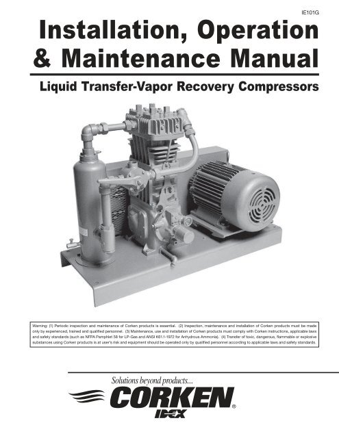
Installation, Operation & Maintenance Manual - Acme Fluid Handling
Installation, Operation & Maintenance Manual - Acme Fluid Handling
Installation, Operation & Maintenance Manual - Acme Fluid Handling

You also want an ePaper? Increase the reach of your titles
YUMPU automatically turns print PDFs into web optimized ePapers that Google loves.
this by withdrawing vapors from the storage tank,compressing them and then discharging into the tankto be unloaded. This procedure slightly decreases thestorage tank pressure and increases the pressure inthe other tank, thereby causing the liquid to flow.Figure 1.1A: Typical Nameplate(Also Serves as the Packing Adjusting Screw Cover)1.1 Liquid Transfer By VaporDifferential PressureCorken LPG/NH 3 compressors are designed totransfer liquefied gases such as butane/propanemixtures (liquefied petroleum gas or LPG) andAnhydrous Ammonia (NH 3 ) from one tank to another.Liquefied gases such as LPG & NH 3 are stored inclosed containers where both the liquid and vaporphases are present.There is a piping connection between the vaporsections of the storage tank and the tank beingunloaded, and there is a similar connection between theliquid sections of the two tanks. If the connections areopened, the liquid will seek its own level and then flowwill stop; however, by creating a pressure in the tankbeing unloaded which is high enough to overcome pipefriction and any static elevation difference between thetanks, all the liquid will be forced into the storage tank(see figure 1.1B). The gas compressor accomplishesThe process of compressing the gas also increases thetemperature, which aids in increasing the pressure in thetank being unloaded.1.2 Residual Vapor RecoveryThe principle of residual vapor recovery is just theopposite of liquid transfer. After the liquid has beentransferred, the four-way control valve (or alternatevalve manifolding) is reversed so that the vapors aredrawn from the tank just unloaded and discharged intothe receiving tank. Always discharge the recoveredvapors into the liquid section of the receiving tank.This will allow the hot, compressed vapors to condense,preventing an undesirable increase in tank pressure (seefigure 1.2A).Residual vapor recovery is an essential part of the valueof a compressor. There is an economical limit to theamount of vapors that should be recovered, however.When the cost of operation equals the price of the productbeing recovered, the operation should be stopped.For most cases in LP Gas and Anhydrous Ammoniaservices, this point is reached in the summer when thecompressor inlet pressure is 40 to 50 psig (3.8 to 4.5Figure 1.1B: Liquid transfer by vapor differential pressure5
Figure 1.2A: Residual Vapor Recoverybars). A good rule of thumb is not to operate beyondthe point at which the inlet pressure is one-fourth thedischarge pressure. Some liquids are so expensive thatfurther recovery may be profitable, but care should betaken that the ratio of absolute discharge pressure toabsolute inlet pressure never exceeds 7 to 1. Furtherexcavation of very high value products would require aCorken two-stage gas compressor.Invariably, there is some liquid remaining in the tankafter the liquid transfer operation. This liquid “heel”must be vaporized before it can be recovered, so do notexpect the pressure to drop immediately. Actually, morevapor will be recovered during the first few minuteswhile this liquid is being vaporized than that during thesame period of time later in the operation. Rememberthat more than half of the economically recoverableproduct is usually recovered during the first hour ofoperation on properly sized equipment.1.3 CompressorConstruction FeaturesThe Corken liquid transfer-vapor recovery compressoris a vertical single-stage, single-acting reciprocatingcompressor designed to handle flammable gases like LPGand toxic gases such as ammonia. Corken compressorscan handle these potentially dangerous gases becausethe LPG/NH 3 is confined in the compression chamberand isolated from the crankcase and the atmosphere.A typical liquid transfer-vapor recovery compressorpackage is shown in figure 1.3A.Corken gas compressors are mounted on oil lubricatedcrankcases that remain at atmospheric pressure.Figure 1.3A: 107-Style Compressor MountingCrankshafts are supported by heavy-duty roller bearingsand the connecting rods ride the crankshaft on journalbearings. With the exception of the small size model 91compressor, all compressor crankcases are lubricated byan automotive type oil pressure system. An automaticallyreversible gear type oil pump circulates oil throughpassages in the crankshaft and connection rod tolubricate the journal bearings and wrist pins (see figure1.3B). Sturdy iron crossheads transmit reciprocatingmotion to the piston.6
Corken’s automatically reversible oil pump designallows the machine to function smoothly in eitherdirection of rotation.Corken compressors use iron pistons that are lockedto the piston rod. The standard piston ring material is aglass-filled PTFE polymer specially formulated for nonlubricatedservices. Piston ring expanders are placedbehind the rings to ensure that the piston rings sealtightly against the cylinder wall.Piston rod packing is used to seal the gas in thecompression chamber and prevent crankcase oil fromentering the compressor cylinder. The packing consistsof several PTFE V-rings sandwiched between a male andfemale packing ring and held in place by a spring (seefigure 1.3C).The typical Corken compressor valve consists of a seat,bumper, one or more spring/s and one or more valve/sdiscs or plates as shown in figure 1.3D. Special heattreatedalloys are utilized to prolong life of the valve inpunishing non-lubricated services. The valve openswhenever the pressure on the seat side exceeds thepressure on the spring side.Figure 1.3C: Compressor Sealing SystemFigure 1.3D: Suction and Discharge ValvesFigure 1.3B: Pressure Lubrication System(Not Available on Model 91)7
Chapter 2—Installing Your Corken Compressor2.1 LocationNOTE: Compressor must be installed in a wellventilated area.Corken compressors are designed and manufactured foroutdoor duty. For applications where the compressor will besubjected to extreme conditions for extended periods suchas corrosive environments, arctic conditions, etc., consultCorken. Check local safety regulations and building codesto assure installation will meet local safety standards.2” MIN.ALL SIDES8” MIN.HEX NUTWASHERCOMPRESSORBASEPLATEGROUT BENEATHBASECONCRETE FOUNDATIONWITH REINFORCEMENTSSHOULD BE USED ON ALLMODELS1/2” “J” BOLTS12” LONGCorken compressors handling toxic or flammable gasessuch as LPG/NH 3 should be located outdoors. Aminimum of 18 inches (45 cm) clearance between thecompressor and the nearest wall is advised to make itaccessible from all sides and to provide unrestricted airflow for adequate cooling.NOISE. Corken vertical compressors sizes model 91through 891 should not exceed an 85 DBA noise levelwhen properly installed.2.2 FoundationProper foundations are essential for a smooth runningcompression system. Corken recommends the compressorbe attached to a concrete slab at least 8 in. thick with a 2in. skirt around the circumference of the baseplate. Thebaseplate should be securely anchored into the foundationby 1/2 in. diameter “J” bolts 12 in. long. Four bolts shouldbe used for models 91, 291, and 491. Six bolts shouldbe used for model 691. The total mass of the foundationshould be approximately twice the weight of the compressorsystem (compressor, baseplate, motor, etc.).NOTE:LOCATE “J” BOLTS PERCOMPRESSOR OUTLINEDIMENSION DRAWINGS.Figure 2.2A: Recommended Foundation Detailsfor Corken Compressors 91 - 691DO NOT SUPPORT PIPING WITH THE COMPRESSOR.Unsupported piping is the most frequent cause ofvibration of the pipe. The best method to minimizetransmission of vibration from the compressor to thepiping is to use flexible connectors (see figure 2.3A).Pipe must be adequately sized to prevent excessivepressure drop between the suction source and thecompressor as well as between the compressor and thefinal discharge point. In most cases, piping should beat least the same diameter as the suction nozzle on thecompressor. Typically, LPG/NH 3 liquid transfer systemsshould be designed to limit pressure drops to 20 psi (1.3bar). Appendix C shows recommended pipe sizes foreach compressor for typical LPG/NH 3 installations.After leveling and bolting down baseplate, the volumebeneath the channel iron baseplate must be groutedto prevent flexing of the top portion of the baseplateand the “J” bolt that extends beyond the foundation.The grout also improves the dampening capabilities ofthe foundation by creating a solid interface between thecompressor and foundation.On some of the longer baseplates, such as with the691–107, a 3 in. hole can be cut in the baseplate for fillingthe middle section of the baseplate with grout.See ED410 Compressor Foundation Design.2.3 PipingProper piping design and installation is as important asthe foundation is to smooth operation of the compressor.Improper piping installation will result in undesirabletransmission of compressor vibration to the piping.Figure 2.3A: On –107 mountings, the fexible connectorsshould be located near the four way valve.8
2.4 Liquid TrapsCompressors are designed to pressurize gas, notto pump liquids. The entry of even a small amountof liquid into the compressor will result in seriousdamage to the compressor.On liquefied gas applications, a liquid trap must be usedto prevent the entry of liquid into the compressor.SERVICE TO PERFORMVALVE POSITION4-WAY A B C1. Unload Tank Car into Position Open Open CloseStorage TankOne2. Recover Vapors from Tank Position Close Open OpenCar into Storage TankTwoFigure 2.3C: Three-Valve Manifold Piping Systemlarge enough to do a good job and these should be replacedby a suitable size valve. The liquid discharge should beconnected to the tank truck pump inlet line rather than theoften oversized filler valve connection in the tank head.Corken offers three types of liquid traps for removal ofentrained liquids. The simplest is a mechanical float trap(see figure 2.4A). As the liquid enters the trap the gasvelocity is greatly reduced, which allows the entrainedliquid to drop out. If the liquid level rises above theinlet, the float will plug the compressor suction. Thecompressor creates a vacuum in the inlet piping andcontinues to operate until the operator manually shuts itdown. The trap must be drained and the vacuum-breakervalve opened before restarting the compressor, to allowthe float to drop back. This type of trap is only appropriatefor use where the operator keeps the compressor underfairly close observation. This trap is provided with the109 and 107 compressor packages (see Appendix C fordetails on standard Corken compressor packages).When the compressor will not be under more-or-lessconstant observation an automatic trap is recommendedIt is of extreme importance to prevent the entry of liquidinto the compressor. The inlet of the compressor shouldbe protected from liquid entry by a liquid trap (see section2.4). It is of equal importance to protect the dischargeof the compressor from liquid. This may be done byinstalling a check valve on the discharge and designingthe piping so liquid cannot gravity-drain back into thecompressor. Make sure to install a check valve on vaporlines discharging to the liquid space of the tank.All piping must be in accordance with the laws andcodes governing the service. In the United States, thefollowing codes apply:For LP Gas – The National Fire Protection AssociationPamphlet No. 58, Standard for the Storage and <strong>Handling</strong>of Liquefied Petroleum Gases.For Ammonia – The American National StandardsInstitute, Inc., K61.1-1989, Storage and <strong>Handling</strong> ofAnhydrous Ammonia.Copies of these are available from NFPA, 60 BaterymarchStreet, Boston, Mass, 02110 and ANSI, 1430 Broadway, NewYork, N.Y., 10018. Install, use and maintain this equipmentaccording to Corken instructions and all applicable federal,state, and local laws and previously mentioned codes.Figure 2.4A: Mechanical Trap10
(see figure 2.4B). The automatic trap replaces the float withelectrical float switches. If the liquid level should rise toohigh, the level switch will open and disconnect the powerto the motor starter, stopping the compressor. This designensures the machine will be protected even when it is notunder close observation and is standard in the 109A and107A mounting configurations.Corken’s most sophisticated trap provides the mostthorough liquid separation (see figure 2.4C). This trap islarger and is ASME code stamped. It contains two levelswitches, one for alarm and one for shutdown. In somecases the alarm switch is used to activate a dump valve(not included with trap) or sound an alarm for the trapto be manually drained by the operator. This trap alsocontains a mist pad. A mist pad is a mesh of interwovenwire to disentrain fine liquid mists. The ASME code trap isstandard in the 109B and 107B mounting configurations.A typical wiring diagram for the liquid level switch isshown in figure 2.4D.If your compressor is equipped with a liquid trapof other than Corken manufacture, make sure it isof adequate size to thoroughly remove any liquidentrained in the suction stream.Typical Float Switch Wiring Diagram(1) = Common, black(2) = Normally closed, blue(3) = Normally open, redFigure 2.4D: Typical Float Switch Wiring DiagramNOTE: The level switch MUST be removed fromthe trap before grounding any welding devices tothe trap or associated piping! Failure to do so willdamage the switch contacts.Figure 2.4B: Automatic Liquid TrapFigure 2.4C: ASME Automatic Liquid Trap11
2.5 Driver <strong>Installation</strong> / FlywheelsCorken vertical compressors may be driven by eitherelectric motors or combustion engines (gasoline, diesel,natural gas, etc.). Corken compressors are usually V-belt driven but they are also suitable for direct driveapplications as well. Direct drive applications require anextended crankshaft to allow the attachment of a rigidmetal coupling.NOTE: Flexible couplings are not suitable forreciprocating compressors. Never operate areciprocating compressor without a flywheel.Drivers should be selected so the compressor operatesbetween 350 to 825 RPM. The unit must not beoperated without the flywheel or severe torsionalimbalances will result that could cause vibration andhigh horsepower requirement. The flywheel shouldnever be replaced by another pulley unless it has ahigher wk2 value than the flywheel.A humid climate can cause problems, particularly inexplosion proof motors. The normal breathing of themotor, and alternating between being warm when runningand being cool when stopped, can cause moist air to bedrawn into the motor. This moist air will condense, andmay eventually add enough water inside the motor tocause it to fail. To prevent this, make a practice of runningthe motor at least once a week on a bright, dry day for anhour or so without the V-belts. In this period of time themotor will heat up and vaporize the condensed moisture,driving it from the motor. No motor manufacturer willguarantee their explosion proof or totally enclosed(TEFC) motor against damage from moisture.For installation with engine drivers, thoroughly reviewinstructions from the engine manufacturer to assure theunit is properly installed.2.6. Crankcase LubricationNon-detergent oil is recommended for Corken verticalcompressors. Detergent oils tend to keep wear particlesand debris suspended in the oil, whereas non-detergentoils let them settle in the bottom of the crankcase.When non-detergent oils are not available, detergentoils may usually be successfully substituted, althoughcompressors handling ammonia, amine, or imine gases arenotable exceptions. These gases react with the detergentand cause the crankcase oil to become corrosive andcontaminated. figures 2.6A and 2.6B show recommendedoil viscosities and crankcase capacities.Synthetic lubricants are generally not necessary. Pleaseconsult your lubricate supplier if you are considering theuse of synthetic oil.Acceptable Crankcase Oil Products for CorkenCompressorsConstant Weight - Non-Detergent - R&O InhibitedOil product ISO VI SAE Ambient Temp.Exxon®TERESSTIC 100 95 30 65° - 100° F68 95 20+ 45° - 70° F46 95 20 35° - 50° FMobil®RARUS 427 Reciprocating 100 95 30 65° - 100° FCompressor OilDTE Oil Heavy Medium 64 95 20+ 45° - 100° FDectol R&O Oil 44 95 20 35° - 50° FConoco®Dectol R&O Oil 100 98 30 35° - 50° F68 97 20+ 45° - 70° F46 99 20 35° - 50° FTexaco®Regal R&O Oil 100 92 30 65° - 100° F68 97 20+ 45° - 70° F46 102 20 35° - 50° FSun®SunVis 900 Oil 100 100 30 65° - 100° F68 100 20+ 45° - 70° F46 100 20 35° - 50° F2.7 Relief ValvesFigure 2.6A: Oil Selection ChartCompressor Approximate CapacityModel Quarts Liters91 0.9 0.8291 1.5 1.4491 3.0 2.8691 7.0 6.6Figure 2.6B: Oil Capacity ChartAn appropriate relief valve must be installed at thecompressor discharge. On Corken 107-style mountedunits a relief valve should be fitted in the pipingbetween the compressor discharge and the four-wayvalve (see figure 1.3A). Relief valves should be made ofa material compatible with the gas being compressed.Local codes and regulations should be checked forspecific relief valve requirements. Also, relief valvesmay be required at other points in the compressor’ssystem piping.2.8 Truck Mounted CompressorsCorken compressors are may be mounted on trucks toperform liquid transfer operations as described in section1.1. The compressor should be mounted so the inspectionplate is accessible for packing adjustment. The compressormust be protected against liquid as explained in section 2.4and a relief valve must be installed in the discharge pipingbefore the first downstream shutoff valve.12
Three types of mountings are typically used. The insidemounting (figure 2.8A) drives the compressor directly offthe PTO shaft. The PTO must be selected to drive thecompressor between 400 and 800 RPM. An extendedcompressor crankshaft is required so the U-joint yokemay connect to the compressor without removing theflywheel. Do not operate the compressor without aflywheel. Use a U-joint with a splined joint and makesure the connections are parallel and in line. The U-jointangle should be less than 15 degrees (see figure 2.8B).Always use an even number of U-joints.Figure 2.8A: Inside Transport MountingDepending on the truck design, the compressor may beoutside or top mounted as shown in figures 2.8C and2.8D to be V-belt driven. Power is transmitted througha U-joint drive shaft, jackshaft with two pillow blockbearings, V-belt sheave and V-belts. An idle pulley maybe used under the truck frame.2.9 Shutdown/Alarm DevicesFor many applications, shutdown/alarm switches willprovide worthwhile protection that may prevent seriousdamage to your compressor system. All electronic devicesshould be selected to meet local code requirements.Shutdown/alarm devices typically used on Corkencompressors are:Figure 2.8B: U-joint Drive for CompressorLow Oil Pressure Switch—shuts down the unit if crankcaseoil pressure falls below 12 psi due to oil pump failure orlow oil level in crankcase.High Temperature Switch—shuts down the unit if thenormal discharge temperature is exceeded. This isstrongly recommended for all applications. Typically,the set point is about 30°F (-1°C) above the normaldischarge temperature.Low Suction, High Discharge Pressure Switch—shutsdown the unit if inlet or outlet pressures are not withinpreset limits.Figure 2.8C: Outside Transport MountingVibration Switch —shuts down the unit if vibrationbecomes excessive. Recommended for units mountedon portable skids.Figure 2.8D: Top Transport Mounting13
Chapter 3—Starting Up Your Corken CompressorNOTE: Before initial startup of the compressor besure the principal of using a compressor for liquidtransfer by vapor differential pressure is understood(see section 1.1). Read this entire chapter, thenproceed with the startup checklist.3.1 Inspection AfterExtended StorageIf your compressor has been out of service for a longperiod of time, you should verify that the cylinder boreand valve areas are free of rust and other debris (seechapter 5 of this IOM manual for valve and/or cylinderhead removal instructions).Figure 3.2A: Flywheel <strong>Installation</strong>Drain the oil from the crankcase and remove thenameplate and crankcase inspection plate. Inspect therunning gear for signs of rust and clean or replace partsas necessary. Replace the crankcase inspection plateand fill crankcase with the appropriate lubricant. Squirtoil on the crossheads and rotate the crankshaft by handto ensure that all bearing surfaces are coated with oil.Rotate unit manually to ensure running gear functionsproperly. Replace nameplate and proceed with startup.3.2 Flywheel and V-belt AlignmentBefore working on the drive assembly, be sure that theelectric power is disconnected. When mounting newbelts, always make sure the driver and compressor areclose enough together to avoid forcing.Improper belt tension and sheave alignment can causevibration, excessive belt wear and premature bearingfailures. Before operating your compressor, check alignmentof the V-grooves of the compressor flywheel and driversheave. Visual inspection often will indicate if the belts areproperly aligned, but use of a square is the best method.The flywheel is mounted on the shaft via a split, taperedbushing and three bolts. These bolts should be tightened inan even and progressive manner until torqued as specifiedbelow. There must be a gap between the bushing flangeand the flywheel when installation is complete. Alwayscheck the flywheel runout before startup and readjustif it exceeds the value listed in Appendix B.Bushing Diameter Bolt TorqueSize In. (cm) Ft.-lb. (kg-meter)SF 4.625 (11.7) 30 (4.1)E 6.0 (15.2) 60 (8.3)J 7.25 (18.4) 135 (18.7)Figure 3.2B: Belt TensionTighten the belts so that they are taut, but not extremelytight. Consult your V-belt supplier for specific tensionrecommendations. Belts that are too tight may causepremature bearing failure. Refer to figure 3.2B.3.3 Crankcase Oil PressureAdjustmentCorken compressor models 291 through 891 areequipped with an automatically reversible gear type oilpump (if your compressor is the splash lubricated Model91, proceed to section 3.4). It is essential to ensurethe pumping system is primed and the oil pressure isproperly adjusted in order to assure smooth operation.Before starting your compressor, check and fill thecrankcase with the proper quantity of lubricating oil.When the compressor is first started, observe thecrankcase oil pressure gauge. If the gauge fails toindicate pressure within 30 seconds, stop the machine.14
Remove the pressure gauge. Restart the compressorand run it until oil comes out of the pressure gaugeopening. Reinstall the gauge.The oil pressure should be about 20 psi (1.4 bars) minimumfor normal service. If the discharge pressure is above 200psi (14.8 bars) the oil pressure must be maintained at aminimum of 25 psi (1.7 bars). A spring-loaded relief valvemounted on the bearing housing opposite the flywheelregulates the oil pressure. As shown in figure 3.3A, turnthe adjusting screw clockwise to increase the oil pressureand counterclockwise to lower it. Be sure to loosen theadjusting screw locknut before trying to turn the screw andtighten it after making any adjustment.6. Verify that strainer elements are in place and clean.7. Verify that cylinder bore and valve areas are clean.8. Check V-belt tension and alignment. Check drivealignment on direct drive units.9. Rotate unit by hand. Check flywheel for wobble or play.10. Check crankcase oil level.11. Drain all liquid traps, separators, etc.12. Verify proper electrical supply to motor and panel.13. Check that all gauges are at zero level reading.14. Test piping system for leaks.15. Purge unit of air before pressurizing with gas.16. Carefully check for any loose connections or bolts.17. Remove all stray objects (rags, tools, etc.) fromvicinity of unit.18. Verify that all valves are open or closed as required.19. Double-check all of the above.After Starting Compressor1. Verify and note proper oil pressure. Shut down andcorrect any problem immediately.2. Observe noise and vibration levels. Correctimmediately if excessive.3. Verify proper compressor speed.3.4 Startup Check ListPlease verify all of the items on this list beforestarting your compressor! Failure to do somay result in a costly (or dangerous) mistake.Before Starting the Compressor1. Become familiar with the function of all piping associatedwith the compressor. Know each line’s use!2. Verify that actual operating conditions will match theanticipated conditions.3. Ensure that line pressures are within cylinderpressure ratings.4. Clean out all piping.Figure 3.3A: Oil Pressure Adjustment5. Check all mounting shims, cylinder and pipingsupports to ensure that no undue twisting forcesexist on the compressor.4. Examine entire system for gas, oil or water levels.5. Note rotation direction.6. Check start-up voltage drop, running amperage andvoltage at motor junction box (not at the starter).7. Test each shutdown device and record set points.8. Test all relief valves.9. Check and record all temperatures, pressures andvolumes after 30 minutes and 1 hour.10. After 1 hour running time, tighten all head bolts, valveholddown bolts, and baseplate bolts. See AppendixB for torque values.15
Chapter 4—Routine <strong>Maintenance</strong> ChartItem to Check Daily Weekly Monthly Six Months YearlyCrankcase oil pressureCompressor discharge pressureOverall visual checkCrankcase oil level ** X**Drain liquid from accumulation pointsClean cooling surfaces on compressorLubricator supply tank level (if any)Check belts for correct tensionInspect valve assembliesLubricate motor bearings in accordance withmanufacturers’ recommendationsInspect motor starter contact pointsPiston rings * X*XXX* Piston ring life varies greatly, depending on application, gas, and operating pressures. Consult factory foradditional recommendations for your specific application.** Change oil every 2,200 hours of operation or every 6 months, whichever occurs first. If the oil is unusuallydirty, change it as often as needed to maintain a clean oil condition. Change replacement filter 4225 withevery oil change.*** Liquid traps should be drained prior to startup.X***XXXXXX16
Chapter 5—Routine Service and Repair ProceduresCAUTION: Always relieve pressure in the unit beforeattempting any repairs. After repair, the unit shouldbe pressure tested and checked for leaks at all jointsand gasket surfaces.If routine maintenance is performed as listed in chapter4, repair service on your Corken gas compressor isgenerally limited to replacing valves or piston rings.When it comes time to order replacement parts, be sureto consult the part details appendix in the back of this<strong>Installation</strong>, <strong>Operation</strong> & <strong>Maintenance</strong> (IOM) manual for acomplete list of part numbers and descriptions.5.1 ValvesTest the compressor valves by closing the inlet pipingvalves while the unit is running; however, do not allowthe machine to operate in this way very long. If theinlet pressure gauge does not drop to zero almostimmediately, one or more of the valves is probably eitherdamaged or dirty. It is possible, of course, that thepressure gauge itself is faulty.Inspect valves for breakage, corrosion, and scratches onthe valve disc and debris. In many cases, valves may simplybe cleaned and reinstalled. If the valves show any damage,they should be repaired or replaced. Replacement isusually preferable, although individual parts are available.If valve discs are replaced, seats should also be lappeduntil they are perfectly smooth. If more than .005 in. mustbe removed to achieve a smooth surface, the valve shouldbe discarded. If discs are replaced without relapping theseat, rapid wear and leakage may occur.Each suction and/or discharge valve assembly is easilyremoved as a unit for inspection. If any part of the valveassembly is broken, the valve assembly should be replaced.See valve assembly parts details in the appendices for acomplete list of part numbers and descriptions.If a valve is leaking due to dirt or any other foreignmaterial that keeps the valve plate and seat from sealing,the valve may be cleaned and reused. New gaskets and/or O-rings should be used to assure a good seal.The valve holddown assemblies and valve assemblies onthe following pages show the various specifications usedon models 91, 291, 491, 691 and 891 compressors. Sincemore than one suction valve arrangement is available foreach model of compressor, it is necessary to know yourcomplete model number so you can identify the valvetype specification number (see example listed below).Model number 491AM 3 FBANSNNValve type = spec 3In most cases for liquid transfer and/or vapor recoverycompressors, the valve type will be spec. 3.Valve Holddown Assemblies: Depending on your modelof compressor, the valve holddown assembly has all or acombination of the following:1. Valve cap2. Valve cap O-ring3. Holddown screw4. Valve cover plate5. Valve cover plate bolts6. Valve cover plate O-ring7. Valve spacer (model 491 only)8. Valve cage9. Valve assembly10. Valve gasketValve Assemblies: Depending on your valve specification,the valve assembly has all or a combination of thefollowing:1. Gasket2. Adjusting screw3. Relief ball spring4. Relief ball5. Valve seat6. Valve plate7. Spacers8. Washer9. Valve spring10. Suction valve post11. Valve bumper12. Valve gasketSee valve holddown and valve assembly part detailsin the appendix for a complete list of part numbersand descriptions.Valve Inspection and/or Replacement for Models 91and 291 CompressorsBefore removing and inspecting the valves, begin bydepressurizing and purging (if necessary) the unit.17
Disassembly1. Unscrew the valve cap and remove O-ring.2. With the special wrench supplied with your compressorat time of purchase, remove the holddown screw.3. After the holddown screw has been removed, thevalve assembly and valve gasket can be lifted out.4. Carefully inspect for dirt or broken/damaged parts.5. Inspect valves for breakage, corrosion, debris andscratches on the valve disc or plate. In many cases,valves may simply be cleaned and reinstalled. If thevalves show any damage, they should be repaired orreplaced. Replacement is usually preferable althoughrepair parts are available. If valve plates are replaced,seats should also be lapped until they are perfectlysmooth. If more than .005 in. must be removedto achieve a smooth surface, the valve should bediscarded. If plates are replaced without relapping theseat, rapid wear and leakage may occur.Assembly1. Insert metal valve gasket into the suction and/ordischarge opening of the head. The metal valvegasket should always be replaced when the valveis reinstalled.2. Insert cleaned or new valve assembly. Make surethe suction and discharge valves are in the propersuction and discharge opening in the head. NOTE:The spec 3 suction valves for a model 91 and 291compressor are pre-set so no adjustments to liquidrelief pressure are necessary.3. Replace the holddown screw and tighten to the valuelisted in Appendix B to ensure the valve gasket isproperly seated. NOTE: Gaskets and O-rings are notnormally reusable.4. Replace the O-ring (or gasket) and valve cap andtighten to the value listed in Appendix B. O-ringssealing the valve caps should be replaced.5. Check bolts and valve holddown screws after firstweek of operation. Re-torque if necessary. SeeAppendix B for torque values.Valve Inspection and/or Replacement for Models491, 691 and 891 CompressorsBefore removing and inspecting the valves, begin bydepressurizing and purging (if necessary) the unit.Disassembly1. Unscrew the valve cap/nut and remove the gasketfrom the coverplate.2. Remove the valve cover plate, O-ring and holddownscrew by removing each of the four bolts. NOTE:Since the holddown screw has been secured with animpact wrench at the factory, you will probably needto wait to remove the holddown screw until after thecover plate has been removed. At this point in time,the holddown screw can be easily removed from thecover plate. The holddown screw on model 691 and891 is most easily removed with the special wrenchsupplied with your compressor at time of purchasing.3. After the cover plate and O-ring have been removed,the valve spacer (model 491 only), valve cage, valveassembly and valve gasket can be lifted out.4. Inspect valves for breakage, corrosion, debris andscratches on the valve plate. In many cases, valvesmay simply be cleaned and reinstalled. If the valvesshow any damage, they should be repaired orreplaced. Replacement is usually preferable althoughrepair parts are available. If valve plates are replaced,seats should also be lapped until they are perfectlysmooth. If more than .005 in. must be removedto achieve a smooth surface, the valve should bediscarded. If plates are replaced without relappingthe seat, rapid wear and leakage may occur.Assembly1. Insert metal valve gasket into the suction and/ordischarge opening of the head. The metal valvegasket should always be replaced when the valve isreinstalled.2. Insert cleaned or new valve assembly. Make surethe suction and discharge valves are in the propersuction and discharge opening in the head.3. Insert the valve cage and valve spacer (NOTE: spacerapplies to model 491 compressor only).4. Replace the O-ring and valve cover plate. Torquebolts to the value listed in Appendix B. CAUTION: Besure the holddown screw has been removed.5. Insert the holddown screw and tighten to the valuelisted in Appendix B to ensure the valve gasket isproperly seated. NOTE: Gaskets and O-rings are notnormally reusable.6. Replace the O-ring (or gasket) and valve cap/nutand tighten to the value listed in Appendix B. O-rings sealing the valve cap should be replaced if theyshow signs of wear or damage. Valve caps sealedby flat metals gaskets should be reinstalled with newgaskets.7. NOTE: Spec 3 suction valves have an adjustingscrew to set the liquid relief pressure. To set theliquid relief pressure, tighten the adjusting screw untilit bottoms, then back out 3/4 turn.8. Check bolts and valve holddown screws after firstweek of operation. Re-torque if necessary. SeeAppendix B for torque values.18
5.2 HeadsA compressor head very seldom requires replacement ifthe compressor is properly maintained. The primary causeof damage to a head is corrosion and the entry of soliddebris or liquid into the compression chamber. Improperstorage can also result in corrosion damage to the head(for proper storage instructions see chapter 6).Many compressor repair operations require removalof the head. While the compressor is disassembled,special care should be taken to avoid damage orcorrosion to the head. If the compressor is to be leftopen for more than a few hours, bare metal surfacesshould be coated with rust preventative.When reassembling the compressor, make sure the boltsare retightened as shown in Appendix B.5.3 Piston Rings andPiston Ring ExpandersFigure 5.3A: Piston RemovalPiston ring life will vary considerably from application toapplication. Ring life will improve dramatically at lowerspeeds and temperatures.5.4 Pistons1. To replace the pistons, depressurize the compressorand purge if necessary.2. Remove the compressor cylinder and head (seesection 5.2).3. Remove the piston head by loosening and removingthe socket head bolts holding the piston head to thepiston platform (see figure 5.3A).4. Next, remove the roll pin with a pair of needle nosepliers. The castellated nut may then be removed andthe piston platform lifted off the end of the piston rod.5. Check the thrust washer and shims for damage andreplace if necessary.6. Before installing the new piston, measure thethickness of the existing shims. For Models 91through 491, the shims are placed between thethrust washer and piston platform. For model 691,the shims are placed between the platform andpiston head (see figures 5.4A and 5.4B).7. Reinstall the piston platform with the same thicknessof shims as before, BUT DO NOT REINSTALL THEROLL PIN.8. Replace the cylinder and install the piston heads withnew piston rings and expanders.9. Now measure dimension “X” shown in the illustration.If this measurement does not fall within the tolerancesshown in Appendix B, remove the piston, adjust theshims as necessary and remeasure the “X” dimension.10. When the piston is properly shimmed, tighten thecastellated nut as shown in Appendix B.11. Now install a new roll pin to lock the castellatedpiston nut in place.1. To replace the piston rings, depressurize thecompressor and purge if necessary.2. Remove the head to gain access to the compressorcylinder.3. Loosen the piston head bolts. Remove the pistonas shown in figure 5.3A by pinching two loosebolts together.4. Piston rings and expanders may then be easilyremoved and replaced. Corken recommendsreplacing expanders whenever rings are replaced.To determine if rings should be replaced, measurethe radial thickness and compare it to the chart inAppendix B.Figure 5.4A: Piston Cross SectionModel Sizes 91 Through 49119
of damage to cylinders is corrosion and the entry of soliddebris or liquid into the compression chamber. Improperstorage can also result in corrosion damage to cylinder(for proper storage instructions see chapter 6).If the cylinder does become damaged or corroded, usea hone to smooth the cylinder bore and then polish itto the value shown in Appendix B. If more than .005in. must be removed to smooth the bore, replace thecylinder. Cylinder liners and oversized rings are notavailable. OVERBORING THE CYLINDER WILL RESULTIN GREATLY REDUCED RING LIFE.Figure 5.4B: Piston Cross SectionModel 69112. Install the piston head and tighten the socket headbolts in an alternating sequence.13. Reinstall the head (see section 5.2) and follow standardstartup procedure. (Note: Some compressors mayhave self-locking nuts without roll pins.)5.5 Piston Rod Packing AdjustmentPiston rod packing should be adjusted or replacedwhenever leakage becomes noticeable. Typically, it isa good idea to replace piston rod packing and pistonrings at the same time. For instructions on adjusting andreplacing the piston rod packing, see section 5.6.NOTE: Inspection of the rod packing is generally notproductive, since packing that cannot be adjusted to anacceptable leakage rate should be replaced.Many compressor repair operations require removal ofthe cylinder. While the compressor is disassembled,special care should be taken to avoid damage orcorrosion to the cylinder. If the compressor is to be leftopen for more than a few hours, bare metal surfacesshould be coated with rust preventative.When reassembling the compressor, make sure the boltsare retightened as shown in Appendix B.Packing Replacement InstructionsCaution: Bleed all pressure from the compressor andpiping, and purge (if necessary), before starting to installnew piston rod packing. After repair, the unit should bepressure tested and checked for leaks at all joints andgasket surfaces. When the compressor is being usedwith toxic, dangerous, flammable or explosive gases, thispressure and leak testing should be done with air or a dry,inert gas such as nitrogen.For simplicity, heads, pistons, and inspection plates arenot shown. For specific construction details and actualpart numbers, consult the appendix in the back of thisIOM manual. Use instructions below that apply to theMODEL and SERIAL NUMBER of your compressor. Becareful to arrange packing sets in the proper order.Cleanliness:Sealing a reciprocating piston rod is a very difficulttask. Keep all parts, tools and your hands clean duringinstallation. Your new packing needs every chance it canget, so keep it clean.Figure 5.5A: Packing Adjusting NutsWorkmanship:Your Corken compressor is a precision piece of equipmentwith very close tolerances. Treat it as such. Never beaton it to get parts in or out.5.6 Cylinder andPacking ReplacementCylinders very seldom require replacement if thecompressor is properly maintained. The primary causeModel 91 Compressor(Refer to Appendix F for packing assembly details)Disassembly of Packing1. Depressurize and open the compressor.20
2. Remove head, piston, cylinder, inspection plate andcrosshead guide.3. Loosen adjusting screw and remove retainer ring,washers, packing spring and old packing fromcrosshead guide.Assembly of Packing1. Clean, then lightly oil, packing area inside thecrosshead guide.2. Slightly thread in the adjusting screw into thecrosshead guide.3. Install packing rings including male and female packingrings one at a time as shown in Appendix F. Push ineach one completely before adding the next ring. Thequantity of packing rings required will vary due totolerances; a good rule of thumb is to put in as manyas are removed.4. Insert thin packing box washer, packing spring andthicker washer into the top of the crosshead guide.5. Tighten adjusting screw until plastic locking deviceengages the first thread in the crosshead guide.6. Oil piston rod and install the packing installationcone (part number 4005) over the threaded end ofthe piston rod.7. Carefully slip the crosshead guide over the pistonrod; otherwise, you may damage the lips of thepacking rings.8. Remove packing installation cone.9. Install the crosshead guide O-ring, cylinder, pistonand head.Model 291 Compressor (serial no. SS55685 and later)Model 491 Compressor (serial no. XC30633 and later)(Refer to Appendix G or H for packing assembly details)Disassembly of Packing1. Depressurize and open the compressor.2. Remove head, pistons and cylinder.3. Remove cartridge holddown screw with specialwrench supplied with the compressor and packingbox cartridge.4. Loosen adjusting screw and remove retainer ring,washers, packing spring and old packing frompacking box cartridge.Assembly of Packing1. Clean, and then lightly oil, packing area insidepacking box cartridge.2. Slightly thread in adjusting screw.3. Install packing rings including male and femalepacking rings, one at a time, as shown in AppendixG or H. Push in each one completely before addingthe next ring. The quantity of packing rings requiredwill vary due to tolerances; a good rule of thumb is toput in as many as are removed.4. Insert thin packing box washer, packing spring andthicker washer.5. Push down on washer and insert retainer ring.6. Tighten adjusting screw until plastic locking deviceengages the first thread in the packing box cartridge.7. Oil piston rod and replace cartridge O-ring.8. Install packing installation cone part number 4005over the threaded end of the piston rod.9. Carefully slip the packing cartridge over the pistonrod; otherwise, you may damage the lips of thepacking rings.10. Remove packing installation cone.11. Install and tighten cartridge holddown screw withspecial wrench.12. Install cylinder O-ring, cylinder, pistons and head.Model 691 Compressor(Refer to Appendix I for packing assembly details)Disassembly of Packing1. Depressurize and open the compressor.2. Remove head, pistons and cylinder.3. Remove cartridge holddown screw with specialwrench supplied with the compressor and packingbox cartridge.4. Loosen adjusting screw and remove retainer ring,washers, packing spring and old packing frompacking box cartridge.Assembly of Packing1. Clean then lightly oil packing area inside packingbox cartridge.2. Thread in adjusting screw until locking device isengaged into first thread of the packing cartridge.3. Install packing rings, including male and female packingrings, one at a time, as shown in Appendix I. Push ineach one completely before adding the next ring.4. Insert a packing washer, packing spring and anotherpacking washer.21
5. Push down on washer and insert retainer ring.6. Oil piston rod and replace cartridge O-ring.7. Install packing installation cone part number 3905over the threaded end of the piston rod.8. Carefully slip the packing cartridge over the pistonrod; otherwise, you may damage the lips of thepacking rings.9. Install and tighten cartridge holddown screw withspecial wrench.10. Replace cylinder O-ring, cylinder, pistons and head.Model D891 Compressor(Refer to Appendix J for packing assembly details)Disassembly of Packing1. Depressurize and open the compressor.2. Remove the cylinder cap, heads, pistons and cylinder.3. To remove the packing barrels, pry upward undereach one and lift entire barrel/cartridge assembly upfrom piston rod.4. Remove the four socket head screws that hold thepacking cartridge to the barrel.Assembly of Packing1. Replace packing as required. The segmented packingand cups are in the barrel. The V-ring packing is inthe cartridge. Note the arrangement of the particularpacking set for the model machine you have.2. Reattach the cartridges to the barrels using the foursocket head screws.3. Install cartridge barrel assemblies, noting thealignment of the barrels as they sit on the crossheadguide. The valve scallops on the barrels must alignproperly with the valves of the cylinder.4. Replace cylinder, pistons, heads and cap. See pistonassembly details for proper clearance values.5. Rotate unit by hand to ensure proper assembly.5.7 Bearing Replacement forCrankcase and Connecting Rod1. To replace the crankcase roller bearings, wrist pinbushing and connecting rod bearings, begin byremoving the head, cylinder, piston, crosshead guideand crosshead assembly.2. Drain the crankcase and remove the inspection plate(s).3. Before disassembly, choose and mark one connectingrod and the corresponding connecting rod cap. DONOT MIX CONNECTING RODS AND CAPS. Loosen andremove the connecting rod bolts in order to remove thecrosshead and connecting rod assembly.5.7.1 Wrist Pin Bushing Replacement1. To replace the wrist pin bushing, remove the retainerrings that position the wrist pin in the crosshead.2. Press out the wrist pin so the crosshead andconnecting rod may be separated. Inspect the wristpin for wear and damage and replace if necessary.3. Press out the old wrist pin bushing and press a newbushing into the connecting rod. DO NOT MACHINETHE O.D. OR I.D. OF THE BUSHING BEFOREPRESSING INTO CONNECTING ROD.4. Make sure the lubrication hole in the bushing matchesthe oil passage in the connecting rod. If the holes donot align, drill out the bushing through the connectingrod lubricant passage with a long drill. Bore thewrist pin bushing I.D. as indicated on the respectiveconnecting rod assembly details. These pages arelocated in the appendices. Over boring the bushing canlead to premature failure of the wrist pin bushing.5. Inspect the oil passage for debris and cleanthoroughly before proceeding.6. Press the wrist pin back into the crosshead and wristpin and reinstall retainer rings. NOTE: The fit betweenthe wrist pin and bushing is tighter than ordinarylubricated air compressors and combustion engines.5.7.2 Replacing Connecting Rod BearingsConnecting rod bearings are easily replaced by removingthe semicircular bearings. Make sure the indentationsin the connecting rod bearing and connecting rod lineup when installing the new bearings. MAKE SURETHE ARROW AND/OR ALIGNMENT NOTCH ONCONNECTING ROD AND CAP ARE ALIGNED.Before reinstalling the crosshead/connecting rodassembly, make sure the crankshaft throw and bearingsurface are clean and lubricated. Tighten the connectingrod bolts to the torques listed in Appendix B.5.7.3 Replacing Crankcase Roller BearingsTo inspect the roller bearings, remove the flywheel from thecrankshaft and then remove the bearing carrier and crankshaftfrom the crankcase. If corrosion or pitting is present, the rollerbearings should be replaced. When replacing roller bearings,always replace the entire bearing, not just the cup or the cone.1. To replace the bearings, press the cups out of thecrankcase and bearing carrier and press the conesoff the crankshaft.22
Figure 5.6.3A: Bearing Carrier Replacement2. Press the new bearings into position and reassemblethe crankshaft and bearing carrier to the crankcase.When reinstalling the bearing carrier, make sure the oilpump shaft slot is aligned with the pin in the crankshaft.Make sure to install the bearing carrier gasket so the oilpassage hole is not blocked (see figure 5.6.3A).3. In order to check the crankshaft endplay, the oilpump must first be removed (see section 5.8).4. Press the end of crankshaft towards the crankcase; ifa clicking noise or motion is detected, the crankshafthas too much endplay. See Appendix B.5. To reduce endplay, remove the bearing cover andremove a thin shim. Recheck the endplay afterreplacing the bearing cover.6. When there is no detectable endplay, the shaft muststill be able to rotate freely. If the crankshaft sticksor becomes abnormally warm, then the crankshaftbearings are too tight. If the crankshaft is too tight,add more shims, but make sure not to over shim.(Appendix B lists the proper crankshaft endplay). Whenthe crankshaft can be rotated freely by hand withproper endplay, the rest of the compressor may bereassembled. If the crankshaft roller bearings are tootight or too loose, premature bearing failure will result.7. Reinstall the flywheel on the crankshaft and checkthe run out as shown in Appendix B.5.8 Oil Pump InspectionIf the compressor operates for a prolonged period withdirty or contaminated crankcase oil, damage to the oilpump may result.1. To check the oil pump, unbolt the pump cover andremove the oil pump, spring guide, spring and oilpump shaft adapter as shown in figure 5.8A.2. Inspect the gears in the oil pump for corrosion orpitting and replace if necessary.3. Check the oil pump shaft bushing in the bearingcarrier. If the bushing is corroded, pitted or worn, theoil pump shaft bushing should be replaced.4. Before reassembling the oil pump mechanism,replace the O-rings in the oil pump cover and on theoil pump adapter shaft (see figure 5.8A).5. Rotate the drive pin in the crankshaft to a verticalposition for easiest reassembly.6. Insert the shaft adapter so it engages the drive pin.7. Next, insert the spring, spring guide and oil pumpassembly. The tang on the oil pump must align withthe slot in the shaft adapter.8. Install the pump cover so the pin on the case is in theopening on the oil pump assembly as shown in figure5.8A. When you are sure the pin is properly aligned,install the cover bolts finger tight.9. Rotate the crankshaft by hand to ensure smoothoperation. Then rotate it in opposite directions,listening for a click, which indicates proper alignmentof the oil pump’s pins and slots.10. Finally, tighten the bolts in an alternating sequence. Seesection 3.3 for directions on oil pressure adjustment.23
5.9 Servicing the Four-Way ValveUnlike older units, new Corken compressors mounted inthe –107 arrangement are being supplied with a non-lubefour-way valve. No maintenance is normally required onthis valve. If you have reason to disassemble the valve,please follow the instructions below (see figures 5.9Aand 5.9B).CAUTION: Always Relieve Pressure In The UnitBefore Attempting Any Repairs.Before Disassembly:1. Record the position marks on the end of the rotor shaft.2. Record the positions of the handle stops on the cap.NOTE: A small amount of silicone grease appliedto each part before assembly facilitates assemblyif allowed.DisassemblyRefer to the drawing for item description.Figure 5.8A1. Remove the hex nut, indicator plate and handle fromthe rotor shaft.2. Remove the four hex head bolts and the cap from thebody. The cap should be rotated until free; do not pry.Inspect cap for wear and damage (see figure 5.9C).Figure 5.9A Figure 5.9B24
7. Place the cap over the rotor shaft.8. Rotate the rotor so the position of the handle stops onthe cap is the same as recorded before disassembly.9. Assemble the four hex head bolts through the capand into the body. Be sure that the body O-ring is inthe proper position and tighten the hex head bolts.Figure 5.9C3. Remove the body O-ring, stem O-ring, cap O-ring,and top rotor washer and discard.4. Remove the rotor and four seals as a unit from thebody. IMPORTANT: Because of the close tolerance,care must be taken to remove the rotor on its axis toprevent damage to the rotor and body. Rotating thehandle with a lifting action will help remove the rotoras shown in figure 5.9D.10. Reassemble the handle, indicator plate and hex nut.Be sure that the handle is assembled so that the stopon the handle mates with the stops on the cap.Chapter 6Extended Storage ProceduresFollowing a few simple procedures will greatly minimize therisk of the unit becoming corroded and damaged. Corkenrecommends the following precautions to protect thecompressor during storage:1. Drain the crankcase oil and refill with rust inhibiting oil.2. Operate for a few minutes while fogging oil into thecompressor suction.3. Relieve V-belt tension.Figure 5.9D5. Discard the four seals. Inspect the rotor for wearand damage.6. Remove the bottom rotor washer and discard.Inspect the body for wear and damage.AssemblyRefer to figure 5.9B. Have the repair kit laid out.4. Plug all openings to prevent entry of insects andmoisture. (The cylinders may also be protected by theuse of a vapor phase inhibitor, silica gel, or dry nitrogengas. If the silica gel is used, hang a tag on the unitindicating that it must be removed before start-up.)5. Store in a dry area, off the ground if possible.6. Rotate the flywheel every two weeks if possible.1. Place the new bottom rotor washer into the body.2. Assemble the four seals and O-rings onto theappropriate surfaces of the rotor.3. Assemble the rotor and seal assembly intothe body. IMPORTANT: Because of the closetolerance, care must be taken to press the rotoron its axis to prevent damage to the rotor andbody. A ring compressor is helpful. Be sure thatthe rotor is bottomed in the body.4. Rotate the rotor so that the position marks on theend of the rotor shaft are the same as recordedbefore disassembly.5. Assemble the new top rotor washer and cap O-ring,onto the shoulder of the rotor.6. Assemble the new stem O-ring and the body O-ringinto their grooves in the rotor and body.25
Appendix AVertical Single-Acting Model Number Identification CodeBase Model 91 291 491 691Inlet 3/4” NPT 3/4” NPT 1-1/4” NPT 2” NPTModel NumberBase X X X X X X X X X XOutlet 3/4” NPT 3/4” NPT 1-1/4” NPT 1-1/2” NPTBase Model F91 F291 F491 F691Inlet 3/4” ANSI 3/4” ANSI 1-1/4” ANSI 2” ANSIOutlet 3/4” ANSI 3/4” ANSI 1-1/4” ANSI 2” ANSIPacking Arrangement Pressurized inlet Standard ACrankcase StyleValvesSplash lubricated Standard N/A N/A N/A JExtended crankshaft Extra cost Extra cost Extra cost N/A EPressure lubricated N/A Standard Standard Standard MStandard with heater N/A Extra cost Extra cost Extra cost MHLiquid relief suction Standard 3Standard valves No extra cost 4Piston Rings and PackingPTFE Standard FAlloy 50 Extra Cost GAluminum Standard BGasket Material Copper No extra cost CLead-iron No extra cost DO-rings Buna-N Standard ANeoprene ®1 No extra cost BViton ®1 Extra cost DTeflon ®1 Extra cost EIntercooler None N/A for single stage compressor N14” flywheel used withextended crankshaftNo charge N/A EFlywheel Heavy duty Extra cost Extra cost Extra cost Extra cost HNo flywheel No extra cost NStandard 14” Standard SProtective Coating No coating Standard NPiston Rod CoatingNitrotec Standard NChrome oxide Extra cost C1 Teflon ® , Neoprene ® , and Viton ® are registered trademarks of the DuPont company.See Appendix C for mounting options.26
Appendix AVertical Single-Acting Model Number Identification CodeBase Model NumberD891Inlet Connection2” WeldOutlet Connection2” WeldShip Weight (lb) 900Model NumberBase X X X X X X X X X XPackingArrangementPacking arranged for padding of distance piece Standard JCrankcase Pressure lubricated Standard MStyle Standard with heater Extra cost MHValvesStandard suction and discharge valves Standard 4Suction valve unloaders Extra cost 9Piston Ringand Packing Teflon ®1 Standard FMaterialGasket Material Aluminum Standard BO-ring Buna-N Standard AMaterial Neoprene ®1 No charge BIntercooler N/A for single stage compressor Standard NFlywheel No flywheel provided No charge NStandard flywheel Standard SProtectiveCoatingNone Standard NPiston RodCoatingNitrotec Standard N1 Teflon ® and Neoprene ® are registered trademarks of the DuPont company.Mounting Selections103 Mounting includes: Steel baseplate, adjustable driver slide base, V-belt drive and enclosed steel belt guard. Pressure gauges aremounted on the compressor. 3107 Mounting includes: Steel baseplate, mechanical liquid trap, non-lube 4-way valve, interconnecting piping, strainer, adjustable driver slidebase, V-belt drive and enclosed steel belt guard. Pressure gauges are mounted on the compressor.107A Mounting includes: All items on the 107 replacing the mechanical float in the liquid trap with a NEMA 7 liquid level switch.107B Mounting includes: All items on the 107 replacing the liquid trap with a larger ASME code liquid trap with 2 NEMA 7 liquid levelswitches set for alarm and shutdown.107TR Mounting includes: All items on the 107 set up to be used as a transport unit. Note that the compressor must have the optional 14”flywheel and extended crankshaft to use this mounting. 2109 Mounting includes: Steel baseplate, mechanical liquid trap, interconnecting piping, adjustable driver slide base, V-belt drive andenclosed steel belt guard. Pressure gauges are mounted on the compressor. 3109A Mounting includes: All items on the 109 replacing the mechanical float in the liquid trap with a NEMA7 liquid level switch. 3109B Mounting includes: All items on the 109 replacing the liquid trap with a larger ASME code liquid trap with 2 NEMA 7 liquid levelswitches set for alarm and shutdown. 3109TR Mounting includes: All items on the 109 set up to be used as a transport unit. Note the compressor must have the optional 14”flywheel and extended crankshaft to use this mounting. 2,32 Not suitable for 691.3 Discharge relief valves are required but not included in these mountings.27
Appendix B—Vertical Single-Acting SpecificationsModels 91–691Equipment Type & OptionsSingle-acting, vertical, reciprocating piston type vapor compressorSingle packed rodNPT or 300# ANSI connectionsApplicationsBulk transferVapor recoveryTank evacuationGas scavengingFeatures and BenefitsSelf-lubricating piston rings:NPT or 300# ANSI connections:Multiple mounting configurations:High efficiency valves:Reversible oil pump:Simplified top down design:Non-lubricated operation to minimize oil in gasVersatility for your applicationVersatility for your applicationQuiet, reliable operationAllows operation in either directionRoutine maintenance is minimally invasiveSpecificationsModel NumberSpecification 91 291 491 691Bore of cylinder inches (mm) 3.0 (76.2) 3.0 (76.2) 4.0 (101.6) 4.5 (114.3)Stroke inches (mm) 2.5 (63.5) 2.5 (63.5) 3.0 (76.2) 4.0 (101.6)Piston displacement cfm (m 3 /hr)minimum @ 400 RPM 4.0 (6.8) 8.0 (13.6) 17.2 (29.2) 29.2 (49.6)maximum @ 825 RPM 8.3 (14.1) 16.5 (28.0) 35.5 (60.3) 60.2 (102.3)Maximum working pressure psig (bar g) 1 335 (23.1)Maximum brake horsepower (kW) 7.5 (5.6) 15 (11) 15 (11) 35 (26.1)Maximum rod load lb (kg) 3,600 (1,632.9) 3,600 (1,632.9) 4,000 (1,814.4) 7,000 (3,175.1)Maximum outlet temperature °F (°C) 350 (177)Bare unit weight lb (kg) 115 (52.2) 160 (72.6) 260 (117.9) 625 (283.5)Maximum flow—propane gpm (m 3 /hr) 50 (11.4) 101 (22.9) 215 (48.8) 361 (82.0)1 These numbers specify pressure-containing abilities of the compressor cylinder and head. For many applications, factors other than the pressurerating will limit the maximum allowable discharge pressure to lower values. These factors include horsepower, temperature and rod load.28
Appendix B—Vertical Single-Acting SpecificationsModels 91–691 Material SpecificationsPart Model Standard Material Optional MaterialHead, Cylinder All Ductile iron ASTM A536 NoneCrosshead guidecrankcase, flywheel, All Gray iron ASTM A48, Class 30 Nonebearing carrierFlange 691 Ductile iron ASTM A536 Steel weld flange91, 291 17-4 PH stainless steelValve seat & bumper 491 Ductile iron ASTM A536 None691 17-4 PH stainless steel91, 291 410 stainless steelValve plate 491 17-7 PH stainless steel None691 410 stainless steelValve spring91, 291, 691 17-7 PH stainless steel491 InconelNoneValve gaskets All Soft aluminum Iron-lead, CopperPiston All Gray iron ASTM A48, Class 30 NonePiston rod All C1050 steel Nitrotec coated Chrome oxideCrosshead All Gray iron ASTM 48, Class 30 NonePiston rings All PTFE, glass and moly filled Alloy 50Ring expanders All 302 stainless steel NoneHead gasket All O-ring, Buna-N Teflon ®1 , Viton ®1 , Neoprene ®1Packing cartridge, All Ductile iron ASTM A536 Noneconnecting rodPacking rings All Teflon ®1 , glass and moly filled Alloy 50Crankshaft All Ductile iron ASTM A536 NoneCon. rod bearing All Bimetal D-2 Babbit NoneWrist pin All C1018 steel NoneWrist pin busing All Bronze SAE 660 NoneMain bearing All Tapered roller NoneInspection plate All Aluminum NoneO-rings All Buna-N PTFE, Viton ®1 , Neoprene ®1Retainer rings All Steel NoneMisc. gaskets All Coroprene None1 Teflon ® , Viton ® and Neoprene ® are registered trademarks of the DuPont company.29
Appendix B—Vertical Single-Acting SpecificationsBolt Torque ValuesValveCrank- Cyl. Valve Hold- Piston Valve ValveConn. Case To Cover Down Lock Piston Cap CapRod Bearing Bearing Inspec X-Head Head Plate Screw Nut Screw Torque TorqueBolt Carrier Cover Plate Guide (1,2) Bolt 2 Torque Torque (w/ Gaskets) (w/ O-Rings)Model ft•lb ft•lb ft•lb ft•lb ft•lb ft•lb ft•lb ft•lb ft•lb in•lb ft•lb ft•lb91 28 38 38 15 30 20 — 40 45 50 40 25291 28 30 30 13 25 20 — 40 45 50 40 25491 30 26 35 8 33 33 35 40 45 100 40 25691 40 40 40 9 40 30 37 40 60 100 40 251 Preliminary tightening – snug all head bolts in the sequence shown. Final torqueing – torque all head bolts in the sequence shown to the listed value.2 Retorque to the listed value after 2 – 5 hours running time.30
Appendix B—Vertical Single-Acting SpecificationsClearances and Dimensions91 291 491 691(M crankcase)**Clearance: “X” piston 0.020 0.020 0.000/0.020 0.000/0.015figure 5.4A & 5.4B 0.044 0.044 0.024/0.044 0.012/0.027Clearance: connecting rod bearing 0.0005 0.0005 0.0005 0.0019to crankshaft journal 0.0025 0.0025 0.0025 0.0035Clearance: wrist pin to wrist pin 0.0009 0.0009 0.0009 0.0020bushing* (max)Cylinder bore diameter (max) 3.009 3.009 4.011 4.515Cylinder finish (RMS) 16-32 16-32 16-32 16-32Piston ring radial thickness (min) 0.082 0.082 0.082 0.082Clearance: oil pump adapter shaft 0.0050 0.0050 0.0050 0.0050to bushing* (max)Crankshaft end play (cold) 0.000 0.000 0.000 0.0020.002 0.002 0.002 0.003Flywheel runout at O.D. (max) 0.020 0.020 0.020 0.020Clearance: crosshead to crosshead 0.011 0.011 0.012 0.013guide bore (max)Crosshead guide bore finish32 RMS (limited number of small pits and scratches are acceptable)* Dimensions for honing are included with new bushings (which must be installed, then honed).** Clearance should be set with machine cold.31
Appendix B—Vertical Single-Acting SpecificationsModel D891Equipment Type & OptionsDouble-acting, vertical, reciprocating piston type vapor compressorDouble packed rodSlip-on weld connectionsApplicationsBulk transferTruck, tank, railcar, barge unloadingLTVR and scavenger applicationsEmergency evacuationFeatures and BenefitsSelf-lubricating piston rings: Non-lubricated operation to minimize oil in gasMultiple materials and configurations: Versatility for your applicationMultiple mounting configurations: Versatility for your applicationHigh efficiency valves:Quiet, reliable operationReversible oil pump:Allows operation in either directionSimplified top down design: Routine maintenance is minimally invasiveFeatures and BenefitsBore of cylinder inches (mm) 4.5 (113)Stroke inches (mm) 4.0 (101.6)Piston displacement cfm (m 3 /hr)minimum @ 400 RPM 56.6 (96.2)maximum @ 825 RPM 113.2 (192.0)Maximum working pressure psig (bar g) 465 (32.1)Maximum brake horsepower (kW) 45 (34)Maximum rod load lb (kg) 7,000 (3,175.2)Maximum outlet temperature °F (°C) 350 (177)Bare unit weight lb (kg) 855 (387.8)Maximum flow—propane gpm (m 3 /hr) 694 (157.6)32
Appendix B—Vertical Single-Acting SpecificationsModel D891 Material SpecificationsPart Standard Material Optional MaterialHead, cylinderDuctile iron ASTM A536Distance pieceCrosshead guide Gray iron ASTM A48, Class 30Crankcase, flywheelBearing carrierFlangeASTM A36 carbon steelValve seat, bumper17-7 PH stainless steelValve plate410 stainless steelValve spring17-7 PH stainless steelValve gaskets Soft aluminum Copper, iron-leadPistonDuctile iron ASTM A536Piston rodC1050 steel, NitrotecCrosshead Gray iron ASTM A48, Class 30Piston rings Teflon ®1 , glass and moly filled Alloy 50Piston ring expanders302 stainless steelHead gasket O-ring, Buna-N Teflon ®1 , Viton ®1 , Neoprene ®1Adapter platePacking cartridgeDuctile iron ASTM A536Connecting rodPacking rings Teflon ®1 , glass and moly filled Alloy 50CrankshaftDuctile iron ASTM A536Connecting rod bearing Bimetal D-2 BabbitWrist pinC1018 SteelWrist pin bushing Bronze SAE 660Main bearingTapered rollerInspection plateAluminumO-rings Buna-N Teflon ®1 , Viton ®1 , Neoprene ®1Retainer ringsSteelMiscellaneous gasketsCoroprene1 Teflon ® , Viton ® and Neoprene ® are registered trademarks of the DuPont company.33
Appendix C—Compressor SelectionCompressor Mounting SelectionsNEMA 7liquid levelswitch1/2" NPTInlet pressure gaugeOutlet pressure gaugeStandard 107 ItemsSteel baseplateV-Belt driveAdjustable driver slide baseEnclosed steel belt guardInlet and outlet pressure gauges40 Micron strainerNon-lube 4-way valveInterconnecting pipingLiquid trap as specified below107 MountingMechanical liquid trap with ball float107A MountingAutomatic liquid trap with one NEMA 7liquid level switch107B MountingAutomatic liquid trap with two NEMA 7liquid level switchesStandard 109 ItemsSteel baseplateV-Belt driveAdjustable driver slide baseEnclosed steel belt guardInlet and outlet pressure gaugesInterconnecting pipingLiquid trap as specified below109 MountingMechanical liquid trap with ball float109A MountingAutomatic liquid trap with one NEMA 7liquid level switch109B MountingAutomatic liquid trap with two NEMA 7liquid level switches34
Appendix C—Compressor SelectionButane Compressor Selection TableDriver HorsepowerLiquid LiquidTransfer Transfer&WithoutResidual ResidualDriver Sheave Size Vapor VaporCapacity Displacement Compressor Pitch Diameter (inches) 2 Recovery Recovery Piping Size 3Service gpm 1 cfm Model RPM 1,750 RPM 1,450 RPM 100°F 80°F 100°F 80°F Vapor Liquid13 4 91 400 A 3.0 A 3.6 3 3 3 3 3/4 1-1/4Small 17 5 91 505 A 3.8 B 4.6 3 3 3 3 3/4 1-1/4bulk 20 6 91 590 B 4.6 B 5.6 3 3 3 3 1 1-1/4plants 24 7 91 695 B 5.4 B 6.6 5 5 5 5 1 1-1/223 7 290, 291 345 A 3.0 A 3.6 2 2 2 2 1 1-1/227 8 91 795 B 6.2 B 7.4 5 5 5 5 1 1-1/226 8 290, 291 390 A 3.4 B 4.0 2 2 2 2 1 1-1/230 9 290, 291 435 A 3.8 B 4.6 3 3 3 3 1 1-1/233 10 290, 291 490 B 4.4 B 5.2 3 3 3 3 1 2Unloading 36 11 290, 291 535 B 4.8 B 5.8 3 3 3 3 1 2single tank 39 12 290, 291 580 B 5.2 B 6.2 5 3 5 3 1 2car or 42 13 290, 291 625 B 5.6 B 6.6 5 5 5 5 1-1/4 2transport 47 14 290, 291 695 B 6.2 B 7.4 5 5 5 5 1-1/4 250 15 290, 291 735 B 6.6 B 8.0 5 5 5 5 1-1/4 2-1/250 15 490, 491 345 A 3.0 A 3.6 5 5 5 5 1-1/4 2-1/253 16 290, 291 780 B 7.0 B 8.6 7-1/2 5 7-1/2 5 1-1/4 2-1/253 16 490, 491 370 A 3.2 A 3.8 5 5 5 5 1-1/4 2-1/256 17 490, 491 390 A 3.4 B 4.0 5 5 5 5 1-1/4 360 18 490, 491 415 A 3.6 B 4.4 5 5 5 5 1-1/4 363 19 490, 491 435 A 3.8 B 4.6 5 5 5 5 1-1/4 365 20 490, 491 445 B 4.0 B 4.8 5 5 5 5 1-1/4 368 21 490, 491 470 B 4.2 B 5.0 5 5 5 5 1-1/4 3Unloading 71 22 490, 491 490 B 4.4 B 5.2 7-1/2 5 7-1/2 5 1-1/4 3two or 75 23 490, 491 515 B 4.6 B 5.6 7-1/2 5 7-1/2 5 1-1/4 3more tank 77 24 490, 491 535 B 4.8 B 5.8 7-1/2 7-1/2 7-1/2 7-1/2 1-1/4 3cars at 81 25 490, 491 560 B 5.0 B 6.0 7-1/2 7-1/2 7-1/2 7-1/2 1-1/4 3one time 84 26 490, 491 580 B 5.2 B 6.2 7-1/2 7-1/2 7-1/2 7-1/2 1-1/4 3or large 87 27 490, 491 605 B 5.4 B 6.4 7-1/2 7-1/2 7-1/2 7-1/2 1-1/4 3transport 91 28 490, 491 625 B 5.6 B 6.6 7-1/2 7-1/2 7-1/2 7-1/2 1-1/2 3with excess 94 29 490, 491 650 B 5.8 B 7.0 10 7-1/2 10 7-1/2 1-1/2 3flow valves 97 30 490, 491 670 B 6.0 10 7-1/2 10 7-1/2 1-1/2 3of adequate 94 30 690, 691 400 B 4.4 B 5.2 7-1/2 7-1/2 7-1/2 7-1/2 1-1/2 3capacity 100 31 490, 491 695 B 6.2 B 7.4 10 7-1/2 10 7-1/2 1-1/2 398 31 690, 691 420 B 4.6 B 5.6 10 7-1/2 10 7-1/2 1-1/2 3107 32 490, 491 740 B 6.6 B 8.0 10 10 10 10 1-1/2 3103 32 690, 691 440 B 4.8 B 5.8 10 7-1/2 10 7-1/2 1-1/2 3110 33 490, 491 760 B 6.8 B 8.0 10 10 10 10 1-1/2 3113 34 490, 491 780 B 7.0 B 8.6 10 10 10 10 1-1/2 3107 34 690, 691 455 B 5.0 B 6.0 10 10 10 10 1-1/2 3111 35 690, 691 475 B 5.2 B 6.2 10 10 10 10 1-1/2 3119 36 490, 491 825 B 7.4 B 8.6 15 10 15 10 1-1/2 3116 36 690, 691 495 B 5.4 A 6.4 10 10 10 10 1-1/2 3120 38 690, 691 510 B 5.6 B 6.8 10 10 10 10 1-1/2 4Unloading 124 39 690, 691 530 B 5.8 B 7.0 10 10 10 10 1-1/2 4large 129 41 690, 691 550 B 6.0 A 7.0 10 10 10 10 1-1/2 4tank cars, 133 42 690, 691 565 B 6.2 B 7.4 10 10 10 10 2 4multiple 137 43 690, 691 585 B 6.4 A 7.4 10 10 10 10 2 4vessels, 142 45 690, 691 605 B 6.6 B 8.0 15 10 15 10 2 4barges or 145 46 690, 691 620 B 6.8 15 10 15 10 2 4terminals 150 47 690, 691 640 B 7.0 A 8.2 15 10 15 10 2 4158 48 690, 691 675 B 7.4 B 8.6 15 15 15 15 2 4171 54 690, 691 730 B 8.0 B 9.4 15 15 15 15 2 4184 58 690, 691 785 B 8.6 15 15 15 15 2 4193 60 690, 691 820 TB 9.0 A 10.6 15 15 15 15 2 4260 82.1 D891 580 5V 7.1 5V 8.5 20 20 20 20 3 6359 113.3 D891 800 5V 9.75 5V 11.8 25 25 25 25 3 61 The capacities shown are based on 70°F, but will vary depending upon piping, fittings used, product being transferred and temperature. Thefactory can supply a detailed computer analysis if required.2 Driver sheaves: 91 (2 belts); 290, 291, 490, 491 (3 belts); 690, 691 (4 belts).3 The piping sizes shown are considered minimum. If the length exceeds 100 ft., use the next larger size.NOTE: Please consult factory for compressors with higher flows.35
Appendix C—Compressor SelectionPropane Compressor Selection TableDriver HorsepowerLiquid LiquidTransfer Transfer&WithoutResidual ResidualDriver Sheave Size Vapor VaporCapacity Displacement Compressor Pitch Diameter (inches) 2 Recovery Recovery Piping Size 3Service gpm 1 cfm Model RPM 1,750 RPM 1,450 RPM 100°F 80°F 100°F 80°F Vapor Liquid23 4 91 400 A 3.0 A 3.6 5 3 3 3 3/4 1-1/4Small 29 5 91 505 A 3.8 B 4.6 5 5 5 5 3/4 1-1/4bulk 34 6 91 590 B 4.6 B 5.6 5 5 5 5 1 1-1/4plants 40 7 91 695 B 5.4 B 6.6 5 5 5 5 1 1-1/239 7 290, 291 345 A 3.0 A 3.6 3 3 3 3 1 1-1/245 8 91 795 B 6.2 B 7.4 7-1/2 7-1/2 7-1/2 7-1/2 1 1-1/244 8 290, 291 390 A 3.4 B 4.0 5 3 3 3 1 1-1/250 9 290, 291 435 A 3.8 B 4.6 5 5 3 3 1 1-1/256 10 290, 291 490 B 4.4 B 5.2 5 5 5 5 1 2Unloading 61 11 290, 291 535 B 4.8 B 5.8 5 5 5 5 1 2single tank 66 12 290, 291 580 B 5.2 B 6.2 7-1/2 5 5 5 1 2car or 71 13 290, 291 625 B 5.6 B 6.6 7-1/2 5 7-1/2 5 1-1/4 2transport 79 14 290, 291 695 B 6.2 B 7.4 7-1/2 7-1/2 7-1/2 7-1/2 1-1/4 284 15 290, 291 735 B 6.6 B 8.0 10 7-1/2 10 7-1/2 1-1/4 2-1/284 15 490, 491 345 A 3.0 A 3.6 7-1/2 7-1/2 5 5 1-1/4 2-1/289 16 290, 291 780 B 7.0 B 8.6 10 10 10 10 1-1/4 2-1/289 16 490, 491 370 A 3.2 A 3.8 7-1/2 7-1/2 7-1/2 5 1-1/4 2-1/295 17 490, 491 390 A 3.4 B 4.0 7-1/2 7-1/2 7-1/2 7-1/2 1-1/4 3101 18 490, 491 415 A 3.6 B 4.4 10 7-1/2 7-1/2 7-1/2 1-1/4 3106 19 490, 491 435 A 3.8 B 4.6 10 7-1/2 7-1/2 7-1/2 1-1/4 3108 20 490, 491 445 B 4.0 B 4.8 10 7-1/2 7-1/2 7-1/2 1-1/4 3114 21 490, 491 470 B 4.2 B 5.0 10 7-1/2 7-1/2 7-1/2 1-1/4 3Unloading 119 22 490, 491 490 B 4.4 B 5.2 10 10 7-1/2 7-1/2 1-1/4 3two or 125 23 490, 491 515 B 4.6 B 5.6 10 10 10 7-1/2 1-1/4 3more tank 130 24 490, 491 535 B 4.8 B 5.8 15 10 10 10 1-1/4 3cars at 136 25 490, 491 560 B 5.0 B 6.0 15 10 10 10 1-1/4 3one time 141 26 490, 491 580 B 5.2 B 6.2 15 10 10 10 1-1/4 3or large 147 27 490, 491 605 B 5.4 B 6.4 15 10 15 10 1-1/4 3transport 152 28 490, 491 625 B 5.6 B 6.6 15 15 15 15 1-1/2 3with excess 158 29 490, 491 650 B 5.8 B 7.0 15 15 15 15 1-1/2 3flow valves 163 30 490, 491 670 B 6.0 15 15 15 15 1-1/2 3of adequate 163 30 690, 691 400 B 4.4 B 5.2 15 15 10 10 1-1/2 3capacity 168 31 490, 491 695 B 6.2 B 7.4 15 15 15 15 1-1/2 3171 31 690, 691 420 B 4.6 B 5.6 15 15 10 10 1-1/2 3179 32 490, 491 740 B 6.6 B 8.0 15 15 15 15 1-1/2 3178 32 690, 691 440 B 4.8 B 5.8 15 15 10 10 1-1/2 3186 34 690, 691 455 B 5.0 B 6.0 15 15 15 10 1-1/2 3193 35 690, 691 475 B 5.2 B 6.2 15 15 15 10 1-1/2 3200 36 690, 691 495 B 5.4 B 6.4 15 15 15 15 1-1/2 3208 38 690, 691 510 B 5.6 B 6.8 20 15 15 15 1-1/2 4215 39 690, 691 530 B 5.8 B 7.0 20 15 15 15 1-1/2 4223 41 690, 691 550 B 6.0 A 7.0 20 15 15 15 1-1/2 4230 42 690, 691 565 B 6.2 B 7.4 20 15 15 15 2 4Unloading 237 43 690, 691 585 B 6.4 A 7.4 20 15 15 15 2 4large 245 45 690, 691 605 B 6.6 B 8.0 20 15 15 15 2 4tank cars, 252 46 690, 691 620 B 6.8 20 20 15 15 2 4multiple 260 47 690, 691 640 B 7.0 A 8.2 20 20 20 15 2 4vessels, 275 48 690, 691 675 B 7.4 B 8.6 25 20 20 20 2 4barges or 297 54 690, 691 730 B 8.0 B 9.4 25 20 20 20 2 4terminals 319 58 690, 691 785 B 8.6 25 20 25 20 2 4334 60 690, 691 820 TB 9.0 A 10.6 30 25 25 20 2 4452 82 D891 580 5V 7.1 5V 8.5 30 30 30 30 3 6623 113 D891 800 5V 9.75 5V 11.8 40 40 30 3 61 The capacities shown are based on 70°F, but will vary depending upon piping, fittings used, product being transferred and temperature. Thefactory can supply a detailed computer analysis if required.2 Driver sheaves: 91 (2 belts); 290, 291, 490, 491 (3 belts); 690, 691 (4 belts).3 The piping sizes shown are considered minimum. If the length exceeds 100 ft., use the next larger size.NOTE: Please consult factory for compressors with higher flows.36
Appendix C—Compressor SelectionAmmonia Compressor Selection TableDriver HorsepowerLiquid LiquidTransfer Transfer&WithoutResidual ResidualDriver Sheave Size Vapor VaporCapacity Displacement Compressor Pitch Diameter (inches) 2 Recovery Recovery Piping Size 3Service gpm 1 cfm Model RPM 1,750 RPM 1,450 RPM 100°F 80°F 100°F 80°F Vapor Liquid23 4 91 400 A 3.0 A 3.6 5 3 3 3 3/4 1-1/4Small 29 5 91 505 A 3.8 B 4.6 5 5 5 3 3/4 1-1/4bulk 34 6 91 590 B 4.6 B 5.6 5 5 5 5 1 1-1/4plants 40 7 91 695 B 5.4 B 6.6 5 5 5 5 1 1-1/243 7 290, 291 345 A 3.0 A 3.6 5 3 3 3 1 1-1/246 8 91 795 B 6.2 B 7.4 7-1/2 5 5 5 1 1-1/245 8 290, 291 390 A 3.4 B 4.0 5 3 3 3 1 1-1/250 9 290, 291 435 A 3.8 B 4.6 5 5 3 3 1 1-1/256 10 290, 291 490 B 4.4 B 5.2 5 5 5 3 1 2Unloading 62 11 290, 291 535 B 4.8 B 5.8 7-1/2 5 5 5 1 2single tank 67 12 290, 291 580 B 5.2 B 6.2 7-1/2 5 5 5 1 2car or 72 13 290, 291 625 B 5.6 B 6.6 7-1/2 5 5 5 1-1/4 2transport 80 14 290, 291 695 B 6.2 B 7.4 7-1/2 7-1/2 7-1/2 5 1-1/4 285 15 290, 291 735 B 6.6 B 8.0 10 7-1/2 7-1/2 7-1/2 1-1/4 2-1/285 15 490, 491 345 A 3.0 A 3.6 7-1/2 7-1/2 5 5 1-1/4 2-1/290 16 290, 291 780 B 7.0 B 8.6 10 7-1/2 7-1/2 7-1/2 1-1/4 2-1/290 16 490, 491 370 A 3.2 A 3.8 10 7-1/2 5 5 1-1/4 2-1/296 17 490, 491 390 A 3.4 B 4.0 10 7-1/2 5 5 1-1/4 3102 18 490, 491 415 A 3.6 B 4.4 10 7-1/2 7-1/2 7-1/2 1-1/4 3107 19 490, 491 435 A 3.8 B 4.6 10 7-1/2 7-1/2 7-1/2 1-1/4 3110 20 490, 491 445 B 4.0 B 4.8 10 7-1/2 7-1/2 7-1/2 1-1/4 3115 21 490, 491 470 B 4.2 B 5.0 10 7-1/2 7-1/2 7-1/2 1-1/4 3Unloading 120 22 490, 491 490 B 4.4 B 5.2 15 10 7-1/2 7-1/2 1-1/4 3two or 126 23 490, 491 515 B 4.6 B 5.6 15 10 7-1/2 7-1/2 1-1/4 3more tank 131 24 490, 491 535 B 4.8 B 5.8 15 10 10 7-1/2 1-1/4 3cars at 138 25 490, 491 560 B 5.0 B 6.0 15 10 10 7-1/2 1-1/4 3one time 142 26 490, 491 580 B 5.2 B 6.2 15 10 10 7-1/2 1-1/4 3or large 148 27 490, 491 605 B 5.4 B 6.4 15 10 10 10 1-1/4 3transport 153 28 490, 491 625 B 5.6 B 6.6 15 10 10 10 1-1/2 3with excess 160 29 490, 491 650 B 5.8 B 7.0 15 15 10 10 1-1/2 3flow valves 165 30 490, 491 670 B 6.0 15 15 15 10 1-1/2 3of adequate 165 30 690, 691 400 B 4.4 B 5.2 15 15 10 10 1-1/2 3capacity 170 31 490, 491 695 B 6.2 B 7.4 15 15 15 10 1-1/2 3173 31 690, 691 420 B 4.6 B 5.6 15 15 10 10 1-1/2 3181 32 490, 491 740 B 6.6 B 8.0 15 15 15 15 1-1/2 3180 32 690, 691 440 B 4.8 B 5.8 15 15 10 10 1-1/2 3188 34 690, 691 455 B 5.0 B 6.0 20 15 10 10 1-1/2 3195 35 690, 691 475 B 5.2 B 6.2 20 15 10 10 1-1/2 3203 36 690, 691 495 B 5.4 B 6.4 20 15 15 10 1-1/2 3211 38 690, 691 510 B 5.6 B 6.8 20 15 15 10 1-1/2 4218 39 690, 691 530 B 5.8 B 7.0 20 15 15 15 1-1/2 4226 41 690, 691 550 B 6.0 A 7.0 20 15 15 15 1-1/2 4233 42 690, 691 565 B 6.2 B 7.4 20 15 15 15 2 4Unloading 240 43 690, 691 585 B 6.4 A 7.4 20 20 15 15 2 4large 248 45 690, 691 605 B 6.6 B 8.0 20 20 15 15 2 4tank cars, 255 45 690, 691 620 B 6.8 25 20 15 15 2 4multiple 263 47 690, 691 640 B 7.0 A 8.2 25 20 15 15 2 4vessels, 278 48 690, 691 675 B 7.4 B 8.6 25 20 15 15 2 4barges or 301 54 690, 691 730 B 8.0 B 9.4 25 20 20 15 2 4terminals 323 58 690, 691 785 B 8.6 30 25 20 20 2 4338 60 690, 691 820 TB 9.0 A 10.6 30 25 20 20 2 4459 82 D891 580 5V 7.1 5V 8.5 40 30 30 30 3 6633 113 D891 800 5V 9.75 5V 11.8 40 40 30 3 61 The capacities shown are based on 70°F, but will vary depending upon piping, fittings used, product being transferred and temperature. Thefactory can supply a detailed computer analysis if required.2 Driver sheaves: 91 (2 belts); 290, 291, 490, 491 (3 belts); 690, 691 (4 belts).3 The piping sizes shown are considered minimum. If the length exceeds 100 ft., use the next larger size.NOTE: Please consult factory for compressors with higher flows.37
Appendix D—Outline DimensionsModels 91–691 and F91–F691 Bare with FlywheelLL1MM1MM1LL1Outline Dimensions—Inches (Centimeters)Model A B C D E F G H J K91, F911-13/16 2-3/8 3-11/16 13/32 5/8 6-1/4 3-7/8 25-5/16 5 22-11/16(4.6) (6.0) (9.4) (1.03) (1.59) (15.9) (9.8) (64.3) (12.7) (57.6)291, F2913-3/8 4-1/8 3-11/16 13/32 5/8 9-13/16 12 25-13/16 5-3/8 23-3/8(8.6) (10.5) (9.4) (1.11) (1.59) (24.9) (30.4) (65.2) (13.7) (59.4)491, F4914-1/8 5 4-11/16 1/2 11/16 10-11/16 13 29-11/16 5-7/8 26-3/16(10.5) (12.7) (11.9) (1.27) (1.75) (27.2) (33.1) (75.4) (14.9) (66.5)691, F6914-3/4 5 5-3/8 9/16 1 14 14-3/8 39-1/8 8-1/4 35-1/8(12.1) (14.0) (13.7) (1.5) (2.5) (35.6) (35.6) (99.4) (21.0) (89.2)“PD” Flywheel Pitch DiameterModel L* L1** M* M1** P Q R S T A-belt Groove B-belt Groove91, F91 3/4 3/4-300 lb 2-3/8 4-1/4 3 14 1-1/8 1-1/4 1/4 13.2 2 13.6 2NPT ANSI (6.0) (10.8) (7.6) (35.6) (2.8) (3.2) (0.63) (33.5) (34.5)291, F291 3/4 3/4-300 lb 2-11/16 4-1/4 3 16 1-1/4 1-1/4 1/4 15.2 3 15.6 3NPT ANSI (6.8) (10.8) (7.6) (40.6) (3.2) (3.2) (0.63) (38.6) (39.6)14 1 13.21 2 13.6 1 2(35.6) (33.5) (34.5)491, F491 1-1/4 1-1/4-300 lb 3-7/8 5-5/8 3 16 1-3/8 1-1/4 5/16 15.2 3 15.6 3NPT ANSI (9.9) (14.3) (7.6) (40.6) (3.5) (3.2) (0.79) (38.6) (39.6)14 1 13.21 2 13.6 1 2(35.6) (33.5) (34.5)691, F691 2 2 2-300 lb 6-3/8 6-15/16 3-13/16 19-1/2 2-1/8 — 1/2 — — 19-1/8 4NPT ANSI (16.1) (17.6) (9.7) (49.5) (5.4) (1.27) (48.5)1 Optional flywheel2 Optional flanges: 1-1/4", 1-1/2" NPT, 1-1/4", 1-1/2" or 2" Weld38* 91, 291, 491, 691 only** F91, F291, F491, F691 only
Appendix D—Outline DimensionsModels 91–691 with 103 MountingOutline Dimensions—Inches (Centimeters)Model A B C D E F G91-10312 15 27-1/2 30 1-1/4 3 5-1/4(30.4) (38.1) (69.8) (76.2) (3.1) (7.6) (13.34)291-10312 15 31-1/2 34 1-1/4 3 5(30.5) (38.1) (80.0) (86.4) (3.2) (7.6) (12.7)491-10315 18 37-1/2 40 1-1/4 4 5-1/4(38.1) (45.7) (95.3) (101.6) (3.2) (10.2) (13.3)691-10317 20 39-1/2 42 1-1/4 4 5.5(43.2) (50.8) (100.3) (106.7) (3.2) (10.2) (14.0)Outline Dimensions—Inches (Centimeters)Model H J K L M N91-10328-11/16 26-3/8 4-15/16 7.75 2-11/16 3/4(72.9) (67.0) (12.5) (19.7) (6.8) NPT291-10328-22/32 26-6/16 4-15/16 7-3/4 2-11/16 3/4(72.9) (67.0) (12.5) (19.7) (6.8) NPT491-10333-11/16 30-3/16 5-3/4 10 3-15/16 3/4(85.6) (76.7) (14.6) (25.4) (10.0) NPT691-10343-1/8 39-1/8 8.25 9.25 6-3/8 2(109.5) (99.4) (21.0) (23.5) (16.2) NPT39
Appendix D—Outline DimensionsModels 91 with -107 or -107A Mounting (model -107A shown below)* Dimensions apply to -107A mounting onlyInches (Centimeters)40
CORKENOILCORKENAppendix D—Outline DimensionsModel 291 with -107 or -107A Mounting (model -107A shown below)CORKENAUTOMATIC LIQUID TRAPINCORKEN* Dimensions apply to -107A mounting onlyInches (Centimeters)41
AUTOMATIC LIQUID TRAPLIQUID LEVEL SWITCH 2462 IS A SINGLEPOLE, SINGLE THROW DEVICEFOR HIGH LEVEL SHUTDOWN - WIRINGCONDUIT MUST BE INSTALLED AT TOP(NORMALLY CLOSED POSITION)FOR HIGH LEVEL ALARM - WIRING CONDUIT(NORMALLY OPEN POSITION)MUST BE INSTALLED AT BOTTOM240 VAC MAX. - 50 AND 60 HZ.100 VA AC MAX. LOAD CONTINUOUS1.5 AMP INRUSH - 120 OR 240 VACMAX. SIZE STARTER COILSIZE 2 - 120V CONTROL VOLTAGESIZE 3 - 240V CONTROL VOLTAGEWIRE ACCORDING TO MANUFACTURER'SINSTRUCTIONS. IF NO INSTRUCTION BOOKWAS RECEIVED, CONSULT THE FACTORY.DRAIN TANK THROUGH 1/4" VALVECORKEN,INC. A Unit Of IDEX CorporationOKLAHOMA CITY, OKLAHOMA USA2509IN2509VALVEROTATIONCORKENCORKENPSIKG/CM¬0 10 20 30 401 20 3OILCORKEN,INC.Appendix D—Outline DimensionsModel 491 with -107 or -107A Mounting (model -107A shown below)CORKEN* Dimensions apply to -107A mounting onlyInches (Centimeters)42
Appendix D—Outline DimensionsModel 691 with -107 or -107A Mounting (model -107A shown below)1-1/4 in. NPTfour waycontrol valveSPROKMNLQCDInches (Centimeters)Outline Dimensions—Inches (Centimeters)Model A B C D E F G H J8-1/4 17 49-1/2 19-3/4 1-1/2 20 52 43-1/4 5-1/2691-107, -107A(21.0) (43.1) (126) (50.1) (3.8) (50.8) (132) (110) (14)Outline Dimensions—Inches (Centimeters)Model K L M N O P Q R S4 1-1/4 1/4 2-11/16* 7-3/4 29 10-1/2 24-1/4 6691-107, -107A(10.1) (3.2) (0.63) (6.8)* (19.6) (73.0) (26.6) (61.0) (15.0)* Dimensions apply to -107A mounting only43
Appendix D—Outline DimensionsModel 91–691 with -109 or -109A Mounting (model -109A shown below)Outline Dimensions—Inches (Centimeters)Model A A1 B C D D1 E F G H J91-109, -109A1-3/16 5-1/4 12 13-5/16 31-1/2 — 1-1/2 15 34 31-3/16 5-1/4(3.7) (13.4) (30.5) (33.8) (80.0) (3.8) (38.1) (86.4) (79.2) (13.3)291-109, -109A5 — 12 15-3/4 39-1/2 — 1-1/2 15 42 30-7/8 5-1/4(12.7) — (30.5) (40.0) (100.3) — (3.8) (38.1) (106.7) (78.4) (13.3)491-109, -109A5-3/4 — 15 18 45-1/2 — 1-1/2 18 48 33-3/4 5-1/4(14.6) — (38.1) (45.7) (115.6) — (3.8) (45.7) (121.9) (85.7) (13.3)691-109, -109A8-1/4 — 17 19-1/4 49-1/2 19-3/4 1-1/2 20 52 43-3/16 5-1/2(30.0) — (43.2) (48.8) (125.7) (50.1) (3.8) (50.8) (132) (109.6) (14.0)Outline Dimensions—Inches (Centimeters)Model K L M N P R S T U91-109, -109A28-3/16 3/4 2-5/16 3 1-1/4 3-5/8 9-1/2 2-3/4 6-3/4(71.6) NPT (5.9) (7.6) (3.2) (9.2) (24.1) (6.9) (17.1)291-109, -109A28-1/2 3/4 2-11/16 3 1-1/4 3-7/8 9-1/2 4-1/2 6-3/4(72.4) NPT (6.8) (7.6) (3.2) (9.9) (24.1) (11.4) (17.1)491-109, -109A30-1/8 1-1/4 4 4 1-1/4 4 10-1/2 5.25 7-3/4(76.5) NPT (10.2) (10.2) (3.2) (10.2) (26.7) (13.3) (19.7)691-109, -109A39-1/8 1-1/2 6-3/8 4 1-1/4 4-1/8 21-7/16 7-1/4 7-3/4(99.3) NPT (16.1) (10.2) (3.2) (10.4) (54.4) (18.4) (19.7)44
Appendix D—Outline DimensionsModel D891 Bare with FlywheelSuctionvalve unloaders(optional)5-1/2"(13.9)5-1/2"(13.9)1/4" NPT drainInlet2" WeldflangeInletpressureguageOutletpressuregaugeOutlet2" Weldflange43-1/4"(109.9)Crankcase heater(optional)35-5/8"(90.4)24-15/32"(62.1)21.2"(53.8)2-1/8"(5.3)8-1/4"(20.9)5-5/8"(14.3)13-1/4"(33.6)4-3/4"(12.0)5-1/2"(13.9)1"(2.5)9-16" (1.4)Hole Diameter5-3/8"(13.6)5-3/8"(13.6)10-1/4"(26.0)Inches (Centimeters)45
Appendix D—Outline DimensionsModel D891 with 103 MountingSuction valve unloaders(optional)Inlet2" Weld flange5-1/2(13.92)5-1/2(13.92)Outletpressure gaugeInletpressure guageOutlet2" Weld flangeBeltguardCrankcase heater(optional)Electric motordriver49-1/4(125.0)41-5/8(105.78)Crankcaseoil drain26-1/8(66.36)3/4(1.91)7(17.78)7(17.78) 22-1/2(57.15)24(60.96)3-9/16(9.05)6(15.24)4(10.21)10(25.40)Low oil pressureswitch(optional)18(45.72)56(142.24)Adjustable driverslide base36(91.40)Use six 3/4"anchor bolts46
Appendix D—Outline DimensionsModel D891 with 107B MountingOutline Dimensions—Inches (Centimeters)Model A B C D E F G H I8-3/32 1-9/16 3-11/16 7 3/4 7-13/16 3-21/32 23-1/4 24D891-107B(20.6) (4.0) (9.4) (17.8) (1.9) (19.9) (9.3) (59.1) (61.0)Outline Dimensions—Inches (Centimeters)Model J K L N O Q R S12-1/2 8-3/4 79-7/16 6 68-1/16 36-5/8 29 10-3/4D891-107B(31.8) (22.2) (201.8) (15.2) (172.9) (93.0) (73.7) (27.3)Outline Dimensions—Inches (Centimeters)Model T U V W X Y Z A16 9 9-1/16 27 30-13/16 45 63 72D891-107B(15.2) (22.9) (23.0) (68.6) (78.3) (114.3) (160.0) (182.9)47
Appendix D—Outline DimensionsModel D891 with 109B MountingOutline Dimensions—Inches (Centimeters)Model A B C D E F G HD891-109B 1-5/16 2 5-3/4 16 7 20 1-13/16 12-1/2(3.3) (5.1) (14.6) (40.6) (17.8) (50.8) (4.7) (31.8)Outline Dimensions—Inches (Centimeters)Model I J L N O P Q RD891-109B 77-9/16 66-3/16 6 39-1/8 27-1/8 39-13/16 8-7/8 4-1/8(197.1) (168.1) (15.2) (99.4) (68.9) (101.1) (22.5) (10.5)Outline Dimensions—Inches (Centimeters)Model S T U V W X Y ZD891-109B 1-1/4 7-3/8 18 28-3/8 24-3/4 65-1/2 68 14-1/2(3.2) (18.7) (45.7) (72.1) (62.8) (166.3) (172.7) (36.8)48
Appendix E—TroubleshootingIn most cases, problems with your Corken gas compressorcan be solved quite simply. This chart lists some of themore frequent problems that occur with reciprocatingcompressors along with a list of possible causes. If youare having a problem which is not listed, or if you cannotfind the source of the problem, consult the factory.ProblemPossible CauseLow capacity 1, 2, 3, 4, 16Overheating 1, 2, 3, 5, 6, 11, 15Knocks, rattles and noise 1, 7, 9, 10, 11, 14Oil in cylinder 8, 14Abnormal piston-ring wear 1, 3, 5, 6, 11, 14, 15Product leaking through crankcase breather 8, 14Product leakage 4, 8, 14, 16Oil leakage around compressor base 17, 18No oil pressure 19, 20Excessive vibration 1, 7, 9, 10, 11, 12, 13, 28Motor overheating or starter tripping out 21, 22, 23, 24, 25, 26, 27, 28Ref. Possible Causes What To Do1. Valves broken, stuck or leaking Inspect and clean or repair2. Piston ring worn Inspect and replace as necessary3. Inlet strainer clogged Clean or replace screen as necessary4. Leaks in piping Inspect and repair5. Inlet or ambient temperature too high Consult factory6. Compression ratio too high Check application and consult factory7. Loose flywheel or belt Tighten8. Worn piston-rod packing Replace9. Worn wrist pin or wrist-pin bushing Replace10. Worn connecting-rod bearing Replace11. Unbalanced load Inspect valve or consult factory12. Inadequate compressor base Strengthen, replace or grout13. Improper foundation or mounting Tighten mounting or rebuild foundation14. Loose valve, piston or packing Tighten or replace as necessary15. Dirty cooling fins Clean weekly16. 4-way control valve not lubricated Inspect and lubricate17. Leaking gas blowing oil from crankcase Tighten packing18. Bad oil seal Replace19. No oil in crankcase Add oil20. Oil-pump malfunction See oil-pressure adjustment21. Low voltage Check line voltage with motor nameplate. Consult power company22. Motor wired wrong Check wiring diagram23. Wire size too small for length or run Replace with correct size24. Wrong power characteristics Voltage, phase and frequency must coincide with motor nameplate.Consult with power company.25. Wrong size of heaters in starter Check and replace according to manufacturer’s instructions26. Compressor overloading Reduce speed27. Motor shorted out See driver installation28. Bad motor bearing Lubricate according to manufacturer’s instructions49
Appendix F—91 and F91 Head and Valve Assembly Details91 Head Assembly35Valve Holddown Assemblies5516677674F91 Head Assembly11811911103SuctionSpec 3SuctionSpec 4DischargeAll Specs212Valve Assemblies1341415241620172125182226192327Suction ValveSpec 350Suction ValveSpec 4Discharge ValveAll Specs
Appendix F—91 and F91 Head and Valve Assembly DetailsHead and Valve Bill of MaterialsRef PartNo. No. Description1. 2374 Head model 912374-X a Head assy. for model 91 (spec 3)2374-X1 Head assy. for model 91 (spec 4)2. 4302 Head model F91 (ANSI flange)3. 7001-037 NC100A Bolt, 3/8-16 x 1" Gr.5 hex head4. 2-235_ c O-ring5. 2714-1 Valve cap6. 2-031_ c O-ring7. 2715 Holddown screw8. 3483-1X Suction valve assy. (spec 3)3483-1X1 b Same as above but with copper gaskets3483-1X2 b Same as above but with iron-lead gaskets9. 3483-X Suction valve assy. (spec 4)3483-X1 b Same as above but with copper gaskets3483-X2 b Same as above but with iron-lead gaskets10. 3485-X Discharge valve assy. (all specs)3485-X1 b Same as above but with copper gaskets3485-X2 b Same as above but with iron-lead gaskets11. 2717 Valve gasket (aluminum)2717-1 b Valve gasket (copper)2717-2 b Valve gasket (iron-lead)12. 5000-77 Retainer ring (spec 3)13. 3977 Suction valve relief housing14. 1411 Spring (spec 3)15. 1410 Ball (spec 3)16. 3483-1 Suction valve seat (spec 3)17. 3972 Suction valve plate (spec 3)18. 4009 Suction spring (spec 3)19. 3484 Suction valve bumper (spec 3)20. 3483 Suction valve seat (spec 4)21. 3972 Suction valve plate (spec 4)22. 4009 Suction spring (spec 4)23. 3484 Suction valve bumper (spec 4)24. 3486 Discharge valve bumper25. 4008 Discharge spring26. 3973 Discharge valve plate27. 3485 Discharge valve seatO-ring CodeA Buna-Na Not shown.b Optionalc _ denotes O-ring code. See O-ring chart to the left for details.d Registered trademarks of the DuPont company.B Neoprene ®d 51CAUTION: Always Relieve Pressure In The Unit Before Attempting Any Repairs.
Appendix F—91 and F91 Piston Assembly Details123456789Piston Assembly Number 1983-X Bill of MaterialsPiston Diameter 3" (7.62 cm)Ref PartNo. No. Description Qty1. 7002-010OC100A Screw, socket head 47207-010A Lock washer 42. 1983 Head, iron 13. 1775 Ring expander 34. 1772 Piston ring 35. 1482 Locknut 16. 1483 Lock pin 17. 1984 Piston platform 18. 1528 Shim washer, thick As1528-1 Shim washer, thin Req.9. 1527 Thrust washer 1Piston Clearance (Cold) aPiston RodModel Minimum Maximum91 0.020" (0.51 mm) 0.044" (1.12 mm)a The distance from the bottom of the head to the top of the piston.CAUTION: Always Relieve Pressure In The Unit Before Attempting Any Repairs.52
Appendix F—91 and F91 Packing Assembly DetailsPacking Assembly Bill of Materials71234Ref PartNo. No. Description Qty1. 2242 Cylinder 12. 2-235_ a O-ring for cylinder 13. 5000-137 Retainer ring 14. 1012 Washer 15. 1628 Packing spring 16. 1714 Packing box washer 17. 1453-1 Male packing ring 18. 1454 b Packing ring 89. 1452-1 Female packing ring 110. 2240 Crosshead guides 111. 1387 Adjusting screw 112. 2526 Crankcase gasket 113. 1452-1X1 Packing set 189567,8,913Assembly AssemblyNumber Name1132-X2 Crosshead - piston-rod assembly1452-1X1 Packing set with 1452-1, 1453-1,1454 (8),1626, 1714*1452-2X1 Packing set (alloy 50) with 1452-1,1453-1,1454-2 (8), 1626, 171410O-ring CodeA Buna-NB Neoprene ®ca _ denotes O-ring code. See O-ring chart above for details.b The quantity of 1454 packing rings required will vary due totolerances. Use cone 4005 for installation of packing.c Registered trademarks of the DuPont company.* Optional equipmentCAUTION: Always Relieve Pressure In The Unit Before AttemptingAny Repairs.11Piston Rod1253
Appendix F—91 and F91 Connecting Rod Assembly Details1223Connecting Rod Assembly Bill of Materials455Ref PartNo. No. Description1. 1132-X2 Crosshead assembly2. 1498 Retainer ring3. 2505 Wrist pin4. 1846-X a,b Wrist pin bushing5. 1599 b Bolt6. 1889-1X Connecting rod assembly7. 1889-1 b Connecting rod8. 1367 b Connecting rod bearing9. 2011 b Dipper10. 1600 b,c Nuta Must be rebored after replacing (0.8754/0.8751 dia.)b Included with connecting rod assemblyc Torque connecting rod nut to 28 ft. lbs.6, 798NotealignmentmarksNever attempt to separate the piston rod and crosshead. When repairbecomes necessary, the entire crosshead assembly must be replaced.CAUTION: Always Relieve Pressure In The Unit BeforeAttempting Any Repairs.1054
Appendix F—91 and F91 Flywheel Assembly DetailsBack SideFlywheel Assembly Bill of MaterialsAssembly AssemblyNumber Name3271-X2 Flywheel assemblyFlywheel: 14” O.D.,2 groove (# 3271)Hub with three blotsand lockwashers(# H SF-1.125)Front Side55
Appendix F—91 and F91 Crankcase Assembly Details233102213171819212012131615145 6 73 41 23118 9 1056
Appendix F—91 and F91 Crankcase Assembly DetailsCrankcase Assembly Bill of MaterialsRef PartNo. No. Description1. 3259 Oil seal2. 1483 Roll pin - 1/8 x 1"3. 7001-037NC075A Hex head 3/8-16 x 3/4", Gr 54. 3260 Bearing carrier5. 2796 Breather ball6. 1279-X O-ring (part of bearing cap assembly)7. 1279-X Breather cap assembly (with O-ring - ref. no. 6)8. 2725 Bearing carrier gasket9. 1807 Roll pin - 1/8 x 5/8"10. 2718 Bearing cup11. 2723 Oil circulating ring12. 2476 Crankshaft13. 2719 Bearing cone14. 2289 Flywheel key15. 2290 Oil ring retainer washer16. 2554 Crankcase17. 1661 Pipe plug - 3/8 NPT sq. or hex18. 2729 Inspection plate gasket19. 2728 Crankcase inspection plate20. 2-112A O-ring21. 1368-X1 Oil bayonet assembly (with O-ring)22. 2721 Bearing adjustment shim (0.005)2721-1 Bearing adjustment shim (0.007)2721-2 Bearing adjustment shim (0.020)23. 2720 Bearing capAssembly AssemblyNumber Name2476-X Crankshaft assembly with 2476, 2290 and 27192476-SX Extended crankshaft assembly with 2719 (2) and 2290, (optional)3260-X Bearing carrier assembly with 3260, 2718, 3259,1279-X, 2-111, 1483, 2796 and 18073271-X2 a Flywheel assembly 14" - 2 groove with H SF-1.125 and 3271a Not shown, not part of the crankcase assembly.Crankcase capacity: 0.9 quarts (0.8 liters)CAUTION: Always Relieve Pressure In The Unit Before Attempting Any Repairs.57
Appendix G—291 and F291 Head and Valve Assembly Details291 Head AssemblyValve Holddown Assemblies55415366776765F291 Head Assembly118119111034SuctionSpec 3SuctionSpec 4DischargeAll Specs212Valve Assemblies Details13146155241620172125182226192327Suction ValveSpec 358Suction ValveSpec 4Discharge ValveAll Specs
Appendix G—291 and F291 Head and Valve Assembly DetailsHead and Valve Bill of MaterialsRef PartNo. No. Description1. 2912 Head model 2912912-X1 Head assy. for model 291 (spec 3)2912-X2 Head assy. for model 291 (spec 4)2. 4300 Head model F291 (ANSI flange)3. 7001-037 NC100A Bolt, 3/8-16 x 1" Gr.5 hex head4. 2731 Center headbolt2732 Gasket for center headbolt5. 2-235_ b O-ring6. 2-113_ b O-ring7. 2714-1 Valve cap8. 2-031_ b O-ring9. 2715 Holddown screw10. 3483-1X Suction valve assy. (spec 3)3483-1X1 a Same as above but with copper gaskets3483-1X2 a Same as above but with iron-lead gaskets11. 3483-X Suction valve assy. (spec 4)3483-X1 a Same as above but with copper gaskets3483-X2 a Same as above but with iron-lead gaskets12. 3485-X Discharge valve assy. (all specs)3485-X1 a Same as above but with copper gaskets3485-X2 a Same as above but with iron-lead gaskets13. 2717 Valve gasket (aluminum)2717-1 a Valve gasket (copper)2717-2 a Valve gasket (iron-lead)14. 5000-77 Retainer ring (spec 3)15. 3977 Suction valve relief housing16. 1411 Spring (spec 3)17. 1410 Ball (spec 3)18. 3483-1 Suction valve seat (spec 3)19. 3972 Suction valve plate (spec 3)20. 4009 Suction spring (spec 3)21. 3484 Suction valve bumper (spec 3)22. 3483 Suction valve seat (spec 4)23. 3972 Suction valve plate (spec 4)24. 4009 Suction spring (spec 4)25. 3484 Suction valve bumper (spec 4)26. 3486 Discharge valve bumper27. 4008 Discharge spring28. 3973 Discharge valve plate29. 3485 Discharge valve seatO-ring CodeA Buna-Na Optionalb _ denotes O-ring code. See O-ring chart to the left for details.c Registered trademarks of the DuPont company.B Neoprene ®c CAUTION: Always Relieve Pressure In The Unit Before Attempting Any Repairs.59
Appendix G—291 and F291 Piston Assembly Details123456789Piston Assembly Number 1983-X Bill of MaterialsPiston Diameter 3" (7.62 cm)Ref PartNo. No. Description Qty1. 7002-010OC100A Screw, socket head 47207-010A Lock washer 42. 1983 Head, iron 13. 1775 Ring expander 34. 1772 Piston ring 35. 1482 Locknut 16. 1483 Lock pin 17. 1984 Piston platform 18. 1528 Shim washer, thick As1528-1 Shim washer, thin Req.9. 1527 Thrust washer 1Piston Clearance (Cold) aPiston RodModel Minimum Maximum291 0.020" (0.51 mm) 0.044" (1.12 mm)a The distance from the bottom of the head to the top of the piston.CAUTION: Always Relieve Pressure In The Unit Before Attempting Any Repairs.60
Appendix G—291 and F291 Packing Assembly DetailsPacking Assembly Bill of Materials378912456 167,8,91011Ref PartNo. No. Description Qty1. 2913-1 Cylinder 12. 2-235_ a O-ring for cylinder 23. 5000-137 Retainer ring 24. 1012 Washer 25. 1628 Packing spring 26. 1714 Packing box washer 27. 1453-1 Male packing ring 28. 1454 b Packing 69. 1452-1 Female packing ring 210. 4398 Cartridge holddown 2screw11. 4394 Packing box cartridge 212. 1387 Adjusting screw 213. 2-135_ a O-ring 2(packing cartridge)14. 4393 Crosshead guide 115. 2702 Crankcase gasket 116. 1452-1X1 Packing set 2not 1192 Locking device 4shownAssembly AssemblyNumber Name Qty1132-X2 Crosshead assembly 21452-1X1 Packing set with 1452-1,1453-1, 1454 (8), 1628, 1714 21213Piston Rod14O-ring CodeA Buna-NB Neoprene ®ca _ denotes O-ring code. See O-ring chart above for details.b The quantity of 1454 packing rings required will vary due totolerances. Use Cone 4005 for installation of packing.c Registered trademarks of the DuPont company.CAUTION: Always Relieve Pressure In The Unit BeforeAttempting Any Repairs.1561
Appendix G—291 and F291 Connecting Rod Assembly Details1223Connecting Rod Assembly Bill of Materials455Ref PartNo. No. Description1. 1132-X2 a Crosshead assembly2. 1498 Retainer ring3. 2505 Wrist pin4. 1846-X a,b Wrist pin bushing5. 1599 b Bolt6. 1889-X Connecting rod assembly7. 1889 b Connecting rod8. 1367 b Connecting rod bearing9. 1600 b,c Nuta Must be rebored after replacing (0.8754/0.8751 dia.)b Included with connecting rod assemblyc Torque connecting rod nut to 28 ft. lbs.Never attempt to separate the piston rod and crosshead. When repairbecomes necessary, the entire crosshead assembly must be replaced.6, 78NotealignmentmarksCAUTION: Always Relieve Pressure In The Unit BeforeAttempting Any Repairs.962
Appendix G—291 and F291 Flywheel Assembly DetailsBack SideFlywheel Assembly Bill of MaterialsAssembly AssemblyNumber Name2549-X1 Flywheel assemblyFlywheel: 16” O.D.,3 groove (# 2549)Hub with three blots andlockwashers(# H SF-1.250)Front Side63
Appendix G—291 and F291 Crankcase Assembly Details12 345610111213149728151617 (Assembly)18191828272625 24 2023 212237353444213839 (assembly)40413646 9474849454450423031 32 33512927 4043 (assembly)5264
Appendix G—291 and F291 Crankcase Assembly DetailsCrankcase Assembly Bill of MaterialsRef PartNo. No.Description1. 1278 Oil seal2. 7001-037NC075A Bolt, 3/8-16 x 3/4, hex head3. 2957 Bearing cover4. 1273 Bearing adjustment shim (0.005")1273-1 Bearing adjustment shim (0.007")1273-2 Bearing adjustment shim (0.020")5. 1500 Bearing cup6. 1368-X Oil bayonet7. 2713 Crankcase inspection plate gasket8. 2958 Crankcase inspection plate9. 2-112A O-ring10. 2955 Crankcase11. 1279 Breather cap12. 2-111A O-ring (breather cap)13. 2796 Breather ball14. 1483 Lock pin - 1/8 x 1"15. 1671 Flywheel key16. 1501 Bearing cone17. 1341-X1 Crankshaft assembly with 1284 (2),1286, 1341, 1501, 2590, 271918. 1284 Crankshaft orifice (2)19. 2719 Bearing cone20. 1286 Pump shaft drive pin21. 2590 Pipe plug - 1/8 NPT, flush seal22. 1280 Filter screen screw23. 1281 Filter screen screw gasket24. 2-116A O-ring (filter screen)25. 1276 Filter screen washer26. 1275 Oil filter screen27. 3289 Pipe plug - 1/4 NPT, flush seal28. 1661 Pipe plug - 3/8 NPT29. 1290 Relief valve adjusting screw30. 1291 Adjusting screw locknut31. 2-011A O-ring (relieve valve adjustment screw)32. 1292 Relief valve spring33. 1293 Relief valve ball34. 2718 Bearing cup35. 2961-X Air release valve assemblywith 2961, 2962, 296336. 1285 Bearing carrier gasket37. 2956 Bearing carrier38. 2-218A O-ring (closure body) (2 required)(Spec 3, 4, 8, 9 only)39. 1515-X Closure cap assembly including 2-218A(2) (Spec 3, 4, 8, 9 only)40. 7001-025NC050A Bolt, 1/4-20 x 1/2, hex head41. 1302 Oil pressure gauge42. 2-228A O-ring (pump cover)43. 4222-X Oil filter assembly44. 1629 Pipe plug - 1/16 NPT, flush seal45. 7001-037NC100A Bolt, 3/8-16 x 1, hex head46. 2805 Pump shaft bushing47. 2850 Pump shaft adapter48. 2852 Oil pump spring49. 2851 Spring guide50. 2849-X Oil pump assembly (individual pumpparts not available)51. 2798 Pump cover pin with 2848-X2848-X Pump cover (includes pin)52. 4225 FilterAssembly AssemblyNumber Name1279-X Breather cap assembly with 1279, 2-111A1341-X1 Crankshaft assembly with 1284 (2), 1286, 1341,1501, 2590, 27191342-X1 a Extended crankshaft assembly with 1284 (2), 1286,1342, 1501, 2590, 27191368-X1 Oil bayonet assembly with 1368-X, 2-112A1419-2X1 Hydraulic unloader assembly (up to 200 psi)(Spec 7, 78 only)1419-2X2 a Hydraulic unloader assembly(200 psi & above)(Spec 7, 78 only)1515-X Closure cap assembly including 2-218A (2)(Spec 3, 4, 8, 9 only)2549-X1 Flywheel assembly, 16" O.D. 3 groove with2549 and 3218 (not part of crankcaseassembly) (not shown)2956-X Bearing carrier assembly with 1285, 1290, 1291,1292, 1293, 1515-X, 2718, 2805, 2806 (2), 2848-X,2849-X, 2850, 2851, 2852, 2956, 2961-X, 2011-A,2-112A, 2-228A.2957-X Bearing cover assembly with 2957 and 12782961-X Air release valve assembly with 2961, 2962, 29633271-X1 a Flywheel assembly, 14" O.D. 2 groove with 3218 and3271 (not part of crankcase assembly) (not shown)4222-X Oil filter assembly with 4222, 4225, 2798, 3289(standard on all models starting January 1, 1993)a Optional equipmentCrankcase capacity: 1.5 quarts (1.4 liters)CAUTION: Always Relieve Pressure In The Unit Before AttemptingAny Repairs.65
Appendix H—490, 491, and F491 Head and Valve Assembly Details490 and 491 Head AssemblyValve Holddown Assemblies67878110111210111011Suction3312121333331313149Discharge15141514154 (prior to FZ44188)161616491 Head Assembly77103101102Suction62171717SuctionSpec 3SuctionSpec 4DischargeAll SpecsDischarge11Valve Assemblies9275282911181118SuctionF491 Head Assembly7 763302019202122 21232225232221312320322426Discharge17171795Suction ValveSpec 3Suction ValveSpec 4Discharge ValveAll Specs66
Appendix H—490, 491, and F491 Head and Valve Assembly DetailsCompressor Head and Valve Bill of MaterialsRef PartNo. No.Description1. 2914 d Head—ductile iron (491)2. 3712 g Head—ductile iron (491)3. 4297 Head—ANSI flanged (F491)4297-1 Head flanged - Din spec. only (F492)4. 1481 c Head gasket (490 and 491)5. 2-253 b,c,e O-ring (491)6. 3442 Pipe plug—1/4" NPT7. 1479 c Center head bolt8. 1480-1 c Center head bolt gasket (copper)1480 c Center head bolt gasket (steel)9. 7005-043NC125A c Bolt, 7/16-14 x 1-1/4" ferry head(490 & 491 prior to serial # FZ44188)7005-043NC150A c Bolt, 7/16-14 x 1-1/2" ferry head(491 serial # FZ44188 and later)10. 1477 Valve screw nut11. 1478 Gasket (steel)1478-1 a Gasket (copper)1478-2 Gasket (iron)12. 1476 Valve holddown screw13. 1475 Valve cover plate14. 2-143 b O-ring for cover plate15. 1409 f Valve spacer16. 2448 Cage17. 1418 Valve gasket (aluminum)1418-1 a Valve gasket (copper)1418-2 a Valve gasket (iron)18. 2446 Bolt19. 2438 Suction valve seat20. 2442 Valve plate21. 2445 f Spacer (two per valve)22. 3355 Washer23. 1407 Valve spring24. 2440 Suction valve bumper25. 2441 Discharge valve bumper26. 2439 Discharge valve seat27. 2533-1 Adjusting screw28. 1411 Relief ball spring29. 1410 Relief ball30. 2532-1 Suction valve seat31. 2534-1 Suction valve post32. 2447 Suction valve bumper33. 7001-043NC125A Bolt (7/16-14 x 1-1/4” hex head)Ref. Valve AssemblyNo. No.Assembly Name101. 2438-X Suction valve assembly(see ref. no. 7, 17, 18, 19, 20, 21(2),22, 23, 24)2438-X1 a Same as 2438-Xbut with copper gaskets2438-X2 a Same as 2438-Xbut with iron-lead gaskets102. 2439-X Discharge valve assembly(see ref. no. 7, 17, 18, 20, 21(2),22, 26, 25)2439-X1 a Same as 2439-Xbut with copper gaskets2439-X2 a Same as 2439-Xbut with iron-lead gaskets103. 2532-1X Suction valve assembly (spec. 3)with aluminum2532-1X1 Same as 2532-1X but with copper2532-1X2 Same as 2532-1X but with iron-leadHead Assembly No. Model Valve Specification2914-X2 f 491 42914-X4 f 491 33712-X1 g 491 33712-X2 g 491 44297-X1 j F491 34297-X2 j F491 44297-1X1 F492 34297-1X2 F492 4O-ring CodeA Buna-NB Neoprene ®ga Optional equipmentb _ denotes O-ring code. See O-ring chart above for details.c Not included in Head Assembly.d Prior to S/N FZ44188.e S/N FZ44188 and later.f Place spacers back to back as shown.g Registered trademarks of the DuPont company.CAUTION: Always Relieve Pressure In The Unit BeforeAttempting Any Repairs.67
Appendix H—490, 491, and F491 Piston Assembly Details123Piston Assembly Number 1985-X Bill of MaterialsPiston Diameter 4" (10.16 cm)456789Ref PartNo. No. Description Qty1. 7002-025OC125A Screw, socket head 87207-025A Lock Washer 82. 1985 Head, iron 13. 1776 Ring expander 34. 1773 Piston ring 35. 1482 Locknut 16. 1483 Lock pin 17. 1986 Piston platform 18. 1528 Shim washer, thick As1528-1 Shim washer, thin Req.9. 1527 Thrust washer 1Piston Clearance (Cold) aPiston RodModel Minimum Maximum490491 b 0.000" (0.00 mm) 0.024" (0.61 mm)491 c 0.020" (0.51 mm) 0.044" (1.12 mm)a The distance from the bottom of the head to the top of the piston.b For 491 compressor with flat gasket.c For 491 compressor with head O-rings.CAUTION: Always Relieve Pressure In The Unit Before Attempting Any Repairs.68
Appendix H—490, 491, and F491 Packing Assembly DetailsPacking Assembly Bill of Materials2378567,8,914161011Ref PartNo. No. Description Qty1. 3713 a Cylinder (491 w/O-ring) 12. 2-243_ b O-ring for cylinder 23. 5000-137 Retainer ring 24. 1012 Washer 25. 1628 Packing spring 26. 1714 Packing box washer 27. 1453-1 Male packing ring 28. 1454 c Packing ring 69. 1452-1 Female packing ring 210. 2801 Cartridge holddown 2screw11. 2799 Packing box cartridge 212. 1387 Adjusting screw 213. 2-139_ b O-ring 2(packing cartridge)14. 2765 d Crosshead guide 115. 1489 Crankcase gasket 116. 1452-1X1 Packing set 2not 1192 Locking device 4shown12139Assembly AssemblyNumber Name1384-X Crosshead assembly1452-1X1 Packing set with 1452-1, 1453-1,1454 (8), 1628, 171414O-ring CodeA Buna-NB Neoprene ®ePiston Roda S/N FZ44188 and laterb _ denotes O-ring code. See O-ring chart above for detailsc The quantity of 1454 packing rings required will vary due totolerances. Use Cone 4005 for packing installation.d S/N XC30633 and latere Registered trademarks of the DuPont company.15CAUTION: Always Relieve Pressure In The Unit BeforeAttempting Any Repairs.69
Appendix H—490, 491, and F491 Connecting Rod Assembly Details1223Connecting Rod Assembly Bill of Materials455Ref PartNo. No. Description1. 1384-X Crosshead assembly2. 1498 Retainer ring3. 1496 Wrist pin4. 1495-X a,b Wrist pin bushing5. 1492 b Bolt6. 1490-X Connecting rod assembly7. 1490 b Connecting rod8. 1491 b Connecting rod bearing9. 1493 b,c Nuta Must be rebored after replacing (0.8754/0.8751 dia.)b Included with connecting rod assemblyc Torque connecting rod nut to 30 ft. lbs.6, 78NotealignmentmarksNever attempt to separate the piston rod and crosshead. When repairbecomes necessary, the entire crosshead assembly must be replaced.CAUTION: Always Relieve Pressure In The Unit BeforeAttempting Any Repairs.970
Appendix H—490, 491, and F491 Flywheel Assembly DetailsBack SideFlywheel Assembly Bill of MaterialsAssembly AssemblyNumber Name2549-X Flywheel assemblyFlywheel: 16” O.D.,3 groove (# 2549)Hub with three blotsand lockwashers(# H SF-1.375)Front Side71
Appendix H—490, 491, and F491 Crankcase Assembly Details1 234561011121314972-1151617818191828272625 24 23 22202135343744213839 (assembly)404136454446 94748495042293031 32 3351274043 (assembly) 5272
Appendix H—490, 491, and F491 Crankcase Assembly DetailsCrankcase Assembly Bill of MaterialsRef PartNo. No.Description1. 3855 Oil seal2. 7001-037NC075A Hex head bolt 3/8-16 x 3/42-1. 7001-031NC075A Hex head bolt 5/16-18 x 3/43. 2847-1 Bearing cover4. 1504 Bearing adjustment shim (0.005")1504-1 Bearing adjustment shim (0.007")1504-2 Bearing adjustment shim (0.020")5. 1500 Bearing cup6. 1508-X Oil bayonet7. 1511 Crankcase inspection plate gasket8. 2853 Crankcase inspection plate9. 2-112A O-ring (oil bayonet & pump shaft)10. 2803 Crankcase11. 1279 Breather cap12. 2-111A O-ring (breather cap)13. 2796 Breather ball14. 1483 Lock pin15. 1663 Flywheel key16. 1501 Bearing cone17. 1499-X Crankshaft assembly with 1284 (2),1286, 1499, 1501, 1503, 25901499-SXExtended crankshaft assembly with1284 (2),1286, 1499-S, 1501, 1503, 259018. 1284 Crankcase orifice (2)19. 1503 Bearing cone20. 1286 Pump shaft drive pin21. 1459 Crankshaft plug (depends on design)2590 Pipe plug (depends on design)22. 1280 Filter screw23. 1281 Filter screen screw gasket24. 2-116A O-ring (filter screen)25. 1276 Filter screen washer26. 1275 Oil filter screen27 3289 Pipe plug28. 1661 Plug 3/8" NPT29. 1290 Relief valve adjusting screw30. 1291 Adjusting screw locknut31. 2-011A O-ring (relief valve adjusting screw)32. 1292 Relief valve spring33. 1293 Relief valve ball34. 1502 Bearing cup35. 2961-X Air release valve assembly with2961, 2962, 296336. 1513 Bearing carrier gasket37. 2804 Bearing carrier gasket38. 2-218A O-ring (closure body) (2)(Spec. 3, 4, 8, 9 only)39 1515-X Closure cap assembly40. 7001-025NC050A Hex head bolt 1/4-20 x 1/241. 1302 Oil pressure gauge42. 2-228A O-ring (pump cover)43. 4222-X Oil filter assembly - external44. 1629 1/16" NPT pipe plug, flush seal45. 7001-037NC100A Hex head bolt 3/8-16 x 146. 2805 Pump shaft bushing47. 2850 Pump shaft adapterRef PartNo. No.Description48. 2852 Oil pump spring49. 2851 Spring guide50. 2849-X Oil pump assembly(individual pump parts not available)51. 2798 Pump cover pin with 2848-X2848-X Pump cover (includes pin)Assembly AssemblyNumber Name1279-X Breather cap assembly with 1279, 2-111A1419-2X1 Hydraulic unloader assembly (up to 200 psi)(Spec. 7, 78 only)1419-2X2 a Hydraulic unloader assembly (200 psi and above)(Spec. 7, 78 only)1499-X Crankshaft assembly with 1284 (2), 1286, 1499,1501, 1503, 25901499-SX Extended crankshaft assembly with 1284 (2),1286, 1499-S, 1501, 1503, 25901508-X1 Oil bayonet assembly with 1508-X, 2-112A1515-X Closure cap assembly including 2-218A (2),(Spec. 3, 4, 8, 9 only)2549-X Flywheel assembly with 2549, 3217 (not part ofcrankcase assembly (not shown)2804-X1 Bearing carrier assembly with 1290, 1291, 1292,1293, 1500, 1508-X1, 1513, 1515-X, 1629 (2),2590, 2804, 2848-X, 2849-X, 2850, 2851, 2852,2961-X, 2-011A, 2-112A, 2-228A2847-1X Bearing cover assembly with 2847-1, 38553271-X a Flywheel assembly with 3271, 3217 (not partof crankcase assembly (not shown)a Optional equipmentCrankcase capacity: 3 quarts (2.8 liters)CAUTION: Always Relieve Pressure In The Unit Before AttemptingAny Repairs.73
Appendix I—691 and F691 Head and Valve Assembly Details690 Head AssemblyValve Holddown Assemblies8459101121312121314131415141551615161611.111684.11717171818691 Head Assembly18845921011021031919195SuctionSpec 3SuctionSpec 4DischargeAll Specs11.24.1Valve Assemblies820721222311.2F691 Head Assembly932425262728291043332262728291043132282926271043031317Suction ValveSpec 3Suction ValveSpec 4Discharge ValveAll Specs74
Appendix I—691 and F691 Head and Valve Assembly DetailsHead and Valve Bill of MaterialsRef PartNo. No.Description1. 1743 Head (690)2. 3458 Head (691)3. 4299 F691 head4. 2144-2 Flange (suction) 2" NPT2144-2S c Flange 2" weld4.1 2144-1.5 Flange (discharge) 1-1/2" NPT2144-1.5SFlange 1-1/2" Weld5. 2-231 d O-ring6. 1744 b Head gasket (690)1744-1 c Head gasket grafoil7. 2-261 a O-ring for head (691)8. 7001-043 NC150A Bolt, 7/16-14 x 1-1/2" hex head9. 2136 Center head bolt10. 1625 Center head bolt gasket (aluminum)1625-1 c Center head bolt gasket (copper)1625-2 c Center head bolt gasket (iron-lead)11. 7005-043 NC125A Bolt, 7/16-14 x 1-1/4" ferry head11.1 7006-043A Reg. lockwasher 7/16"11.2 7005-050 NC150A Bolt, 1/2-13 x 1-1/2" ferry head12. 2714 Valve cap2714-1 Valve cap, grooved for O-ring13. 2-031 a O-ring for valve cap2716 Gasket (aluminum) for valve cap2716-1 c Gasket (copper) for valve cap2716-2 c Gasket (iron) for valve cap14. 2715 Holddown screw15. 7001-043 NC137A Bolt, 7/16-14 x 1-3/8" hex head16. 1764 Valve cover plate17. 2-235 a O-ring (cover plate)18. 2797 Valve cage19. 2114 Valve gasket (aluminum)2114-1 c Valve gasket (copper)2114-2 c Valve gasket (iron)20. 5000-77 Retainer ring21. 3977 Suction valve relief housing (spec 3)22. 1411 Spring23. 1410 Relief ball24. 3948 Valve seat (spec. 3)25. 2534-1 Suction valve post (spec 3)26. 3872 Inner valve plate27. 3871 Outer valve plate28. 3929 Inner valve spring29. 3928 Outer valve spring30. 3949 Valve bumper (spec. 3)31. 3857 Valve bumper32. 3920 Valve stud33. 3856 Valve seatRef. AssemblyNo. No.Assembly Name101. 3948-X Suction valve assembly (spec. 3)(includes valve gasket)3948-X1 c Same as abovebut with copper gasket3948-X2 c Same as abovebut with iron-lead gasket102. 3856-X Suction valve assembly(includes valve gasket)3856-X1 c Same as abovebut with copper gasket2255-X2 c Same as abovebut with iron-lead gasket103. 3857-X Discharge valve assembly(includes valve gasket)3857-X1 c Same as abovebut with copper gasket3857-X2 c Same as abovebut with iron-lead gasket104. 3146-X1 Valve repair kit (suction & discharge)Head Assembly Number Models Valve Specification1743-X 690 33458-X 691 3a For O-ring material coding, see page A500.b Not included in head assembly.c Optional.d S/N NQ51455 and later. Earlier models use gasket # 2177.75
Appendix I—691 and F691 Piston Assembly Details123Piston Assembly Number 1987-X Bill of MaterialsPiston Diameter 4.5" (11.43 cm)45678Ref PartNo. No. Description Qty1. 7002-025OC125A Screw, socket head 87207-025A Lock washer 82. 1987 Head, iron 13. 1740 Ring expander 34. 1739 Piston ring 35. 1482 Locknut 16. 1483 Lock pin 17. 1735 Shim washer, thick As1735-1 Shim washer, thin Req.8. 1988 Piston platform 1Piston Clearance (Cold) aPiston RodModel Minimum Maximum690 0.000" (0.00 mm) 0.012" (0.30 mm)691 0.015" (0.38 mm) 0.027" (0.68 mm)a The distance from the bottom of the head to the top of the piston.CAUTION: Always Relieve Pressure In The Unit Before Attempting Any Repairs.76
Appendix I—691 and F691 Packing Assembly DetailsPacking Assembly Bill of Materials789567,8,9123417101511Ref PartNo. No. Description Qty1. 3457 Cylinder 12. 2-247_ a O-ring for cylinder 23. 1749 Cartridge holddown 2screw4. 5000-175 Retainer ring 25. 1731 Packing spring 26. 1728 Packing washer 27. 1724 Male packing ring 28. 1725 Packing ring 49. 1723 Female packing ring 210. 2407 Packing box cartridge 211. 2-233_ a O-ring 2(packing cartridge)12. 1748 Cartridge plate 213. 5000-350 Retainer ring 214. 2405 Crosshead guide 115. 1722 Adjusting screw 216. 1761 Crankcase gasket 117. 1725-2X Packing set 2not 1192 Locking device 4shownfor adj. screwnot 2893 Locking device cartrigeshownholddown screw1213Piston Rod14Assembly AssemblyNumber Name1717-X1 Crosshead assembly “P” style1725-2X Packing set with 1723, 1724,1725 (4), 1728, 17312405-X Crosshead guide assembly with1748 (2), 2405, 5000-350 (2)3544-X4 Crosshead assembly “M” styleO-ring CodeA Buna-NB Neoprene ®ba _ denotes O-ring code. See O-ring chart above for details.b Registered trademarks of the DuPont company.16CAUTION: Always Relieve Pressure In The Unit BeforeAttempting Any Repairs.771 Registered trademarks of the DuPont company.
Appendix I—691 and F691 Connecting Rod Assembly Details1223Connecting Rod Assembly Bill of Materials455Part NumberRef Spec. K,P Spec. MNo. Only Only Description1. 1717-X1 3544-X4 Crosshead assy.2. 1498 3590 Retainer ring3. 1718 3540 Wrist pin4. 1495-X a,b 3541-X b,d Wrist pin bushing5. 1726 b 1726 b Bolt6. 1720-X 3785-X1 Conn. rod assy.7. 1720 b 3785 b Connecting rod8. 1719 b 3542 b Conn. rod bearing9. 1727 b,c 1727 b,c Nut6, 78Notealignmentmarksa Must be rebored after replacing (0.8754/0.8751 dia.)b Included with connecting rod assemblyc Torque connecting rod nut to 40 ft. lbs.d Must be rebored after replacing (1.1256/1.252 dia.)Never attempt to separate the piston rod and crosshead. When repairbecomes necessary, the entire crosshead assembly must be replaced.CAUTION: Always Relieve Pressure In The Unit BeforeAttempting Any Repairs.978
Appendix I—691 and F691 Flywheel Assembly DetailsBack SideFlywheel Assembly Bill of MaterialsAssembly AssemblyNumber Name1762-X1 Flywheel assemblyFlywheel: 19.5” O.D.,4 groove (# 1762)Hub with three blotsand lockwashers(# H E-2.125)Front Side79
Appendix I—691 and F691 Crankcase Assembly Details1213 515 141816171920101234 5 6112898472126252324222729 3130373839513235364041343347485049285756Inside ofBearing Carrier59423360554344454652535550585455Oil Passage HoleImportant! Line up hole ingasket with oil passage hole.Pump Cover Oil/Filter Adapter426061(Includes all parts shownexcept #52 and #53)Pumpside of adapter shown forproper orientation of cover andlocation of pump cover pin.80
Appendix I—691 and F691 Crankcase Assembly DetailsCrankcase Assembly Bill of MaterialsRef PartNo. No.Description1. 1737 Bearing cone2. 3638 Spacer3. 3635 Drive sprocket4. 1284 Crankshaft orifice5. 2135 Drive pin6. 2933 Link pin7. 3786 Crankshaft8. 3503 Flywheel key9. 3580 Bearing cone10. 3786-X1 Crankshaft assembly11. 7001-031NC075A Bolt, 5/16 - 18 x 3/4" hex head12. 2122 Inspection cover13. 2123 Gasket, inspection cover14. 2-210A O-ring15. 3225-X1 Oil bayonet assembly (w/O-ring)16. 2126 Breather ball17. 3579 Bearing cup18. 3589 Bearing adjustment shim (.005")2589-1 Bearing adjustment shim (.007")2589-2 Bearing adjustment shim (.020")19. 3539 Bearing cover20. 3526 Oil seal21. 1280 Filter screw22. 1281 Gasket, filter23. 2-116A O-ring24. 1276 Washer25. 1275 Oil filter screen26. 3443 Pipe plug, 1/2" NPT steel27. 3221 Crankcase28. 7001-037NC100A Bolt, 3/8 - 16 x 1" hex head Gr. 529. 3875 Access cover30. 7003-025NC037E Screw, 1/4 - 20 x 3/8"31. 3874 Gasket, access cover32. 1515-X Closure cap assembly33. 7001-025NC050A Bolt, 1/4 - 20 x 1/2" hex head34. 1515 Closure cap35. 1516 Closure body36. 2-118A O-ring37. 1290 Relief valve adjusting screw38. 2-011A O-ring39. 1291 Adjusting screw locknut40. 1292 Relief valve spring41. 1293 Relief valve ball42. 4222-X c Oil filter adapter assembly (w/pin)43. 2-228A O-ring44. 2849-1X c Oil pump assembly45. 2851 Spring guide46. 2852 Oil pump spring47. 3219 Pump shaft adapter48. 2-112A O-ring49. 2805-X b Pump shaft bushing50. 1629 Pipe plug, 1/16 NPT fl. seal51. 1736 Bearing cup52. 1302 Oil pressure gauge53. 1044 Bushing, 1/8 x 1/4 NPT54. 3220-2 Bearing carrierRef PartNo. No.Description55. 3289 Pipe plug, 1/4 NPT fl. seal56. 2131 Bearing carrier gasket57. 2961-X Air release valve assembly58. 2590 Pipe plug, 1/8 NPT fl. Seal59. 4225 Filter60. 2798 Pump cover pin (included w/4222-X)61. 3220-2X Bearing carrier assemblyAssemblyNumber3852-Xa3852a3918a1762a3221-X1a3221-X2a3221-X3a3221-X4aAssemblyNameFlywheel assembly (D891 only)Flywheel 21.2", 5V, 5 grooveFlywheel hub type J2 - 1/8" bore (D891 only)Flywheel 19 - 1/2" AB, 4 grooveCrankcase assembly (M3, 4, 8, 9) without lubricationCrankcase assembly (M7, 78) without lubricationCrankcase assembly (L3, 4, 8, 9) without lubricationCrankcase assembly (L7, 78) without lubricationa Not shownb Must be rebored and honed after replacing (0.876"/0.875" diameter)c Caution: To avoid damage during assembly, refer to installationInstruction <strong>Manual</strong> IE400.CAUTION: Always Relieve Pressure In The Unit Before AttemptingAny Repairs.81
Appendix J—D891 Head and Valve Assembly Details891 HeadValve Hold-down AssemblyValve Assemblies41567214815202391616311NOTE:Studprotrudesthis side.10121718192119171821132015Compressor Head and Valve Bill of MaterialsSuctionor DischargeRef PartNo. No. Description1. 3923 Cylinder cap2. 3924 Cylinder head - 4-1/2"3. 2-246__ b O-ring4. 7001-050 NC150A Bolt, 1/2 - 13 x 1-1/2" hex head Gr 5(Torque to 65 ft•lbs)5. 2714-1 Valve cap6. 2-031__ b O-ring7. 2715 Holddown screw8. 1764 Valve cover plate9. 2-235__ b O-ring10. 3570-1 Valve cage11. 3732-X Suction valve assembly (6")12. 3733-X Discharge valve assembly (6")13. 2114 a Valve gasket14. 7001-043 NC150A Bolt, 7/16 - 14 x 1-1/2" hex head(Torque to 37 ft•lbs)15. 3827 Valve seat (6")16. 3828 Stud17. 3830 c Valve plate, outer18. 3831 c Valve plate, inner19. 3829 c Spring20. 3826 Valve bumper (6")21. 3805-X1 c Valve repair kit (1st stage)SuctionValveO-ring CodeA Buna-NB Neoprene ®dDischargeValvea Included with valve assemblyb _ denotes O-ring code. See O-ringchart above for details.c Included with valve repair kit.d Registered trademarks of the DuPontcompany.CAUTION: Always relieve pressure in theunit before attempting any repairs.82
Appendix J—D891 Piston Assembly Details12345Piston Assembly Number 3925-X1 Bill of MaterialsPiston Diameter 4.5" (11.43 cm)67895Piston RodRef PartNo. No. Description Qty1. 7002-025 TP100A Screw, orlo gr. 8 4(Torque to 8 ft•lbs)2. 3927 Piston cap 13. 2902 Shim washer (thick) Asreq.3902-1 Shim washer (thin) Asreq.4. 3604 Lock nut (Torque to 150 ft•lbs) 15. 3730 Thrust washer 26. 3925 Piston cap 17. 1739 Piston rings (PTFE) 41739-2 Piston rings (Alloy) 41739-3 Piston rings (PEEK) 48. 1740 Expander ring 49. 3603 Shim washer (thick) Asreq.3603-1 Shim washer (thin) Asreq.10. Loctite tube - 620 3812 1Piston Clearance (Cold)Model Top Min. a Top Max. a Bottom Min. b Bottom Max. bD891 0.084" (2.13 mm) 0.104" (2.64 mm) 0.010" (0.25 mm) 0.020" (0.50 mm)a The distance from the bottom of the head to the top of the piston.b The distance from the bottom of the piston to the top of the crosshead guide.CAUTION: Always Relieve Pressure In The Unit Before Attempting Any Repairs.83
Appendix J—D891 Crosshead Guide Assembly Details172876Crosshead Guide Bill of Materials1051161263454914 1516Ref PartNo. No. Description Qty1. 3922 Cylinder 12. 1054 Drain valve 1(lubricated models)3. 1071 Nipple, 1/4" x close 14. 2-246_ a O-ring for cylinder 25. 3442 Pipe plug, 1/4" NPT 36. 7001-050NC175A Bolt, 1/2" 13 x 1-3/4" 24hex head gr 57. 3793-2S Flange (inlet/outlet) 28. 2-231_ a O-ring for flange 29. 3253 Roll pin 110. 2405-1 Crosshead guide 111. 1064 Elbow, 1/4" NPT 112. 3974 Tag 113. 1761 Gasket, crankcase 114. 1760 Gasket, inspection cover 115. 1721 Inspection cover 116. 7012-010NC025B Bolt, 10 - 24 x 1/4" Phillip hd. 1013O-ring CodeA Buna-NB Neoprene ®ba _ denotes O-ring code. See O-ring chart above for details.b Registered trademarks of the DuPont company.CAUTION: Always Relieve Pressure In The Unit Before Attempting Any Repairs.NOTE:Packing barrel installation:1. Use packing installation cone #905 on the piston rod.2. Insert small barrel first, use finger holes to align slinger ring on to the rod. Slipthe packing barrel into place.3. Align pin with slot in large packing barrel.4. Slip large packing barrel in place.84
Appendix J—D891 Packing Assembly DetailsPacking Assembly Bill of Materials1819171155620796207962079620893162410111012 or 141312 or 14104“J” & “K”RadTanRadTanRadTanTanTan19121314562089620896208962089“J” & “K”“R”TanTanTanTanTanTanTanTanPacking Direction141312“R”NOTE: Use installation Cone#3905 over piston rod wheninstalling packing.Ref PartNo. No.Description1. 3926 Packing barrel - 4-1/2"2. 3885 Cartridge3. 1732 b Oil slinger ring4. 5000-175 Snap ring5. 3906 Crush gasket6. 3817 Packing cup (Not included in3810-X1 packing set)7. 3810 Segmented packing(radial - tangent) pair8. 3814 Segmented packing(tangent - tangent) pair9. 3811 Back-up ring10. 1728 Washer11. 1731 Spring12. 1724 Male packing ring13. 1725 Packing ring14. 1723 Female packing ring15. 2-238_ a,c O-ring16. 2-231_ a O-ring17. 7002-025OC100A Screw, 1/4-20 x 1" socket head18. 1725-X Packing set19. 3810-X1 e Packing set20. 2-036_ a,d Cup O-ringa _ denotes O-ring code. See O-ring chart for details.b Slinger ring is loose within the packing cartridge until fitted on thepiston rod. Must be put in from the bottom of the cartridge.c Insert item 17 into the groove in the bottom of the barrel.d Starting with S.N. NN51397.e Packing cup O-ring not included in packing set.f Registered trademarks of the DuPont company.Identification of Packing SpecificationExample: Model Number D891 K M4FBAPacking Spec.CAUTION: Always RelievePressure In The Unit BeforeAttempting Any Repairs.Segmented packing align pin with hole #3810 SPEC “J” & “K”Piston (Pressure) SideTo CrankcaseO-ring CodeA Buna-NB Neoprene ®bRadial Cut(without pin)Tangent Cut(with pin)Back-upringSegmented packing align pin with hole #3814 SPEC “J” & “K”Piston (Pressure) SideTo Crankcase85Tangent Cut(without pin)Tangent Cut(with pin)Back-upringIMPORTANT: Identify and line up the rings before installing. Be surethey face the way shown here and that the pin and hole are alignedwhen assembled.
Appendix J—D891 Connecting Rod Assembly Details1223Connecting Rod Assembly Bill of Materials455Ref PartNo. No. Description1. 3544-X3 Crosshead assembly2. 3590 Retainer ring3. 3540 Wrist pin4. 3541-X a,b Wrist pin bushing5. 1726 b Bolt6. 3785-X a Connecting rod assembly7. 3785 a Connecting rod8. 3542 a Connecting rod bearing9. 1727 a,c Nuta Included with connecting rod assemblyb Torque connecting rod nut to 40 ft. lbs.c Must be rebored after replacing (1.1256/1.252 dia.)6, 78NotealignmentmarksNever attempt to separate the piston rod and crosshead. When repairbecomes necessary, the entire crosshead assembly must be replaced.CAUTION: Always Relieve Pressure In The Unit BeforeAttempting Any Repairs.986
Appendix J—D891 Flywheel Assembly DetailsBack SideFlywheel Assembly Bill of MaterialsAssembly AssemblyNumber Name3852-X Flywheel assemblyFlywheel: 21.2” O.D.,5 groove (# 3852)Hub with three blotsand lockwashers(# H E-2.125)Front Side87
Appendix J—D891 Crankcase Assembly Details1213 515 141816171920101234 5 6112898472126252324222729 3130373839513235364041343347485049285756Inside ofBearing Carrier59423360554344454652535550585455Oil Passage HoleImportant! Line up hole ingasket with oil passage hole.Pump Cover Oil/Filter Adapter426061(Includes all parts shownexcept #52 and #53)Pumpside of adapter shown forproper orientation of cover andlocation of pump cover pin.88
Appendix J—D891 Crankcase Assembly DetailsCrankcase Assembly Bill of MaterialsRef PartNo. No.Description1. 1737 Bearing cone2. 3638 Spacer3. 3635 Drive sprocket4. 1284 Crankshaft orifice5. 2135 Drive pin6. 2933 Link pin7. 3786 Crankshaft8. 3503 Flywheel key9. 3580 Bearing cone10. 3786-X1 Crankshaft assembly11. 7001-031NC075A Bolt, 5/16 - 18 x 3/4" hex head12. 2122 Inspection cover13. 2123 Gasket, inspection cover14. 2-210A O-ring15. 3225-X1 Oil bayonet assembly (w/O-ring)16. 2126 Breather ball17. 3579 Bearing cup18. 3589 Bearing adjustment shim (.005")2589-1 Bearing adjustment shim (.007")2589-2 Bearing adjustment shim (.020")19. 3539 Bearing cover20. 3526 Oil seal21. 1280 Filter screw22. 1281 Gasket, filter23. 2-116A O-ring24. 1276 Washer25. 1275 Oil filter screen26. 3443 Pipe plug, 1/2" NPT steel27. 3221 Crankcase28. 7001-037NC100A Bolt, 3/8 - 16 x 1" hex head Gr. 529. 3875 Access cover30. 7003-025NC037E Screw, 1/4 - 20 x 3/8"31. 3874 Gasket, access cover32. 1515-X Closure cap assembly33. 7001-025NC050A Bolt, 1/4 - 20 x 1/2" hex head34. 1515 Closure cap35. 1516 Closure body36. 2-118A O-ring37. 1290 Relief valve adjusting screw38. 2-011A O-ring39. 1291 Adjusting screw locknut40. 1292 Relief valve spring41. 1293 Relief valve ball42. 4222-X c Oil filter adapter assembly (w/pin)43. 2-228A O-ring44. 2849-1X c Oil pump assembly45. 2851 Spring guide46. 2852 Oil pump spring47. 3219 Pump shaft adapter48. 2-112A O-ring49. 2805-X b Pump shaft bushing50. 1629 Pipe plug, 1/16 NPT fl. seal51. 1736 Bearing cup52. 1302 Oil pressure gauge53. 1044 Bushing, 1/8 x 1/4 NPT54. 3220-2 Bearing carrierRef PartNo. No.Description55. 3289 Pipe plug, 1/4 NPT fl. seal56. 2131 Bearing carrier gasket57. 2961-X Air release valve assembly58. 2590 Pipe plug, 1/8 NPT fl. Seal59. 4225 Filter60. 2798 Pump cover pin (included w/4222-X)61. 3220-2X Bearing carrier assemblyAssembly AssemblyNumber Name3852-X a Flywheel assembly (D891 only)3852 a Flywheel 21.2", 5V, 5 groove3918 a Flywheel hub type J2 - 1/8" bore (D891 only)1762 a Flywheel 19 - 1/2" AB, 4 groove3221-X1 a Crankcase assembly (M3, 4, 8, 9) without lubrication3221-X2 a Crankcase assembly (M7, 78) without lubrication3221-X3 a Crankcase assembly (L3, 4, 8, 9) without lubrication3221-X4 a Crankcase assembly (L7, 78) without lubricationa Not shownb Must be rebored and honed after replacing (0.876"/0.875" diameter)c Caution: To avoid damage during assembly, refer to installationInstruction <strong>Manual</strong> IE400.CAUTION: Always Relieve Pressure In The Unit Before AttemptingAny Repairs.89
CORKEN, INC. • A Unit of IDEX Corporation3805 N.W. 36th St., Oklahoma City, OK 73112 U.S.A.Phone (405) 946-5576 • (800) 631-4929Fax (405) 948-7343Visit our website at http://www.corken.comor e-mail us at info.corken@idexcorp.comPrinted in the U.S.A.November 2006