![(D) HK Normalien Aktuell [GB]](https://img.yumpu.com/42904226/1/500x640/d-hk-normalien-aktuell-gb.jpg)
(D) HK Normalien Aktuell [GB]
(D) HK Normalien Aktuell [GB]
(D) HK Normalien Aktuell [GB]
- No tags were found...

Create successful ePaper yourself
Turn your PDF publications into a flip-book with our unique Google optimized e-Paper software.
Oilless Guide Elements2·8690·2001·4 °subject to alterationsd99
Oilless Guide ElementsGeneral DescriptionOilless Guide Elements with embeddedsolid lubricants are used in applicationsof linear or rotary motion in toolmaking,general machine construction andsimilar engineering uses. The structureof the base material provides closelyspaced deposits of solid lubricant –properties and specifications as per tablebelow.The elements satisfy highest demandsin terms of load bearing capacity atlow sliding speeds, within an extensivetemperature band.The lubricant deposits are arranged instaggered geometrical patterns, thus en -suring optimal lubrication effect alongthe sliding motion, especially withcounter bearings which are hardenedand ground.The sliding surfaces should be lightlygreased with lithium grease emulsion,prior to commissioning.On flat guideways and pillar guides, from25 to 30 per cent of the sliding surfacesconsist of lubricant deposits. Surfacesof counter bearings must have a groundfinish, preferably with a lay parallel withthe sliding motion.Choice of Element-TypeStandard:– for general uses at temperaturesup to 200°CSpecial Types on requestAdvantages of Oilless GuideElements– good emergency sliding properties– highest carrying capacity at low speed– use under water or with chemicalsolutions– extremely wide temperatureresistance – hot and cold– damping properties in presenceof vibrationPV valueThe permissible bearing load is determinedfrom the pressure and the PV value, whichdefines the bearing wear.The PV value is the product of surfacepressure (P) and running velocity (V).The permissible bearing load is determinedfrom the PV value.PV = P × V (N/cm 2 × m/min.)P = F/A (N/cm 2 )F = max. load (N)A = projected area of the bearingSurface pressure, temperature,speed and lubricationSurface pressure Temp. Speed PV valuemax. (N/cm 2 ) (C°) (m/min.) (N/cm 2 × m/min) Lubrication5000 80 15 10000 Initial3000 150 60 20000 Pressure IubricationOilless Guide Elements – Material Datachemical composition % CU 60–66 Brinell hardness HB 10 180–210 stroking velocity m/min 15 electric conductanceAl 5,0–7,5 shear strength N/mm 2 560 co-efficient of friction 0,04–0,10 m/(Ω × mm 2 ) 7–8Fe 2,0–4,0 yield limit temperature conductance alt. flexural strengthMn 2,5–5,0 Rp 0,2 N/mm 2 450 W/(m × K) 45–55 N/mm 2 ±150balance: Zn elongation to fracture A5 % 8 temperature resistance °C +300 ratio sliding surfacespecific density kg/dm 3 8,2 elongation % 12 co-efficient of thermal to lubricanttensile strength Rm N/mm 2 770 modulus of elasticity expansion 1,6–2,0 × 10 –5 /°C deposits (%) 25–30kN/mm 2 105–115 co-efficient of shrinkage % 1,8–2,3d100subject to alterations2·9207·8·6 °
Thrust Washers2053.70. Bronze with Non-Liquid Lubricant2053.70.Material:Bronze with Non-Liquid Lubricant,oilless lubricating.Note:For combination loads usetogether with Bushes 2052.70.Direction of MotionEmbedded non-liquid lubricant(section)Ordering Code (example):Thrust Washer = 2053.70.d 3 = 20,2 mm = 2053.70.020Order No = 2053.70.020Fixing:from d 3 = 10,2 2 × M3from d 3 = 20,2 2 × M5from d 3 = 40,2 2 × M6from d 3 = 50,3 4 × M6from d 3 = 60,3 4 × M8from d 3 = 90,5 4 × M10Screws not included.2053.70.d 3 10,2 12,2 13,2 14,2 15,2 16,2 18,2 20,2 25,2 30,2 35,2 40,2 45,3 50,3 55,3 60,3 65,3 70,3 75,3 80,3 90,5 100,5 120,5d 4 30 40 40 40 50 50 50 50 55 60 70 80 90 100 110 120 125 130 140 150 170 190 200d 5 20 28 28 28 28 28 35 35 40 45 50 60 67,5 75 85 90 95 100 110 120 140 160 175s 3 3 3 3 3 3 3 5 5 5 5 7 7 8 8 8 8 10 10 10 10 10 10F 3 3 3 3 3 3 3 5 5 5 5 6 6 6 6 8 8 8 8 8 10 10 102·10897·9·4 °subject to alterationsd101
ohne BMOilless Guide Bushes<strong>GB</strong> 2008/2Bronze with Non-Liquid Lubricant 2052.70.2052.70.Material:Bronze with Non-Liquid Lubricant,oilless lubricating.Note:Recommended fits for:press fits: H 7 borecontact adhesive: G 7 bore(if required secure with set screw).Notice:Note that press fitment reduces inside bush diameter.Bushes can be used with radial or axial motion.Direction of MotionEmbedded non-liquidlubricant (section)Ordering Code (example):Guide Bush = 2052.70.d 1 = 40 mm = 2085.70.040.d 2 = 50 mm = 2085.70.016.050.l 1 = 60 mm = 2052.70.040.050.060Order No = 2052.70.040.050.0602052.70.d 1 8 10 12 13 14 15 16 18 19 20 24 25 28 30 31,5 32 35 38 40 45d 2 12 14/15 18 19 20 21 22 24 25 26/28/30 32 32/33/35 38 38/40/42 40 42 44/45 48 50/55 55/56/60r 0,5 0,5 0,5 0,5 0,5 0,75 0,75 0,75 0,75 0,75 0,75 0,75 0,75 0,75 0,75 0,75 0,75 1,5 1,5 1,5l 4 2 2 2 2 2 2 2 2 2 4 4 4 4 4 4 4 4 4 4 4l 1 8 ● ●/–10 ● ●/● ● ● ● ● ●12 ● ●/– ● ● ● ●15 ● ●/– ● ● ● ● ● ● –/ ●/–16 ● ● ● ● ● –/ ●/● – /●/●20 ●/– ● ● ● ● ● ● –/ ●/● – /●/● ●/●/– – /● ●/–25 ● ● ● ● ● –/ ●/● – /●/● ●/●/– ●/● ●/●30 ● ● ● ● ● –/ ●/● – /●/● ● ●/●/– ● ● ●/● ● ●/● ●/●/●35 ● ● –/ ●/● – /●/● ●/●/– ●/● ●/● ●/●/●37 ● –/ ●/–40 ● ● ●/●/● – /●/● ● ●/●/– ● ● ●/● ● ●/● ●/●/●47 ● – /●/–50 –/ ●/– ●/●/● ●/●/– ●/● ●/● ●/●/●60 – /●/– ●/●/● ● ●/● ●/● ●/●/●70 ●/– –/–/●77 ● ●/–80 ●/– –/–/●d102subject to alterations2 · 10895 · 2007 · 3 l
Oilless Guide Bushes2052.70. Bronze with Non-Liquid Lubricant2052.70.Material:Bronze with Non-Liquid Lubricant,oilless lubricating.Note:Recommended fits for:press fits: H 7 borecontact adhesive: G 7 bore(if required secure with set screw).Notice:Note that press fitment reduces insidebush diameter.Bushes can be used with radial oraxial motion.Direction of MotionEmbedded non-liquidlubricant (section)2 · 10896 · 2007 · 3 l2052.70.d 1 50 55 60 63 65 70 75 80 85 90 100 110 120 125 130 140 150 160d 2 60/62/65 70 74/75 75 80 85/90 90/95 96/100 100 110 120 130 140 145 150 160 170 180r 1,5 2 2 2 2 2 2 2 2 2 2 2 2 2 2 2 2 2l 4 4 4 4 4 4 4 4 4 4 4 4 4 4 4 4 4 4 4l 1 30 ●/●/● ●/●35 ●/●/– ●/● ●/–3740 ●/●/● ● ●/● ●/– ●/●4750 ●/●/● ● ●/● ● ●/● ●/●60 ●/●/● ● ●/● ● ● ●/● ●/● ●/● ● ●70 ●/●/● ● ●/● ● ● ●/● ●/● ●/● ● ●7780 ●/–/● ●/● ● ● ●/● ●/● ●/● ● ● ● ● ●95 ●/–/–100 –/–/● –/● ●/– ●/● ●/● ● ● ● ● ● ● ● ● ●120 ● ●/● ● ● ● ● ● ●130 ●140 – /● ● ● ●150 ● ●subject to alterationsd103
Oilless Guide Bushes with collarBronze with Non-Liquid Lubricant 2085.70.2085.70.Material:Bronze with Non-Liquid Lubricant,oilless lubricating.Note:Fit for receiving bore: G 7.Bushes can also be fitted with Loctite.Direction of MotionEmbedded non-liquid lubricant(section)Ordering Code (example):Guide Bush = 2085.70.d 1 = 16 mm = 2085.70.016.l 1 = 30 mm = 2085.70.016.030Order No = 2085.70.016.0302085.70.d 1 12 16 20 24d 2 16 20 26 30d 3 18 24 28 35r 2 2 2 2l 1 l 220 14 ● ● ● ●25 19 ● ● ● ●30 24 ● ● ● ●d104subject to alterations2·8694·8·5 °
Oilless Guide Bushes with collar2085.71. Bronze with Non-Liquid Lubricant2085.71.Material:Bronze with Non-Liquid Lubricant,oilless lubricating.Note:Fit for receiving bore: H 7.Notice:Bushes can be used with radial oraxial motion.Ordering Code (example):Guide bush = 2085.71.d 1 = 16 mm = 2085.71.016.l 1 = 25 mm = 2085.71.016.025Order No = 2085.71.016.025Direction of MotionEmbedded non-liquid lubricant(section)2085.71.d 1 10 12 13 14 15 16 20 25 30 31,5 35 40 45 50 55 60 63 70 75 80 90 100 120d 2 14 18 19 20 21 22 30 35 40 40 45 50 55 60 65 75 75 85 90 100 110 120 140d 3 22 25 26 27 28 29 40 45 50 50 60 65 70 75 80 90 85 105 110 120 130 150 170l 3 2 3 3 3 3 3 5 5 5 5 5 5 5 5 5 7,5 7,5 7,5 7,5 10 10 10 10l 4 2 2 2 2 2 2 3 3 3 3 3 3 3 3 3 4 4 4 4 4 4 4 4r 1 1 1 1 1 1 1 2 2 2 2 2 2 2 2 2 3 3 3 3 3 3 3 3r 2 0,4 0,4 0,4 0,4 0,5 0,5 0,5 0,5 0,5 0,6 0,6 0,6 0,6 0,6 0,7 0,7 0,7 0,7 0,7 0,8 0,8 0,8 0,82·10689·8·3 °l 1 l 215 13 12 12 12 12 12 10 1020 18 17 17 17 17 17 15 15 15 15 15 1525 22 22 20 20 2030 27 27 25 25 25 25 25 25 2535 30 3040 35 35 35 35 35 35 35 35 32,550 45 45 45 45 45 42,5 42,560 55 55 55 52,5 50 5067,5 6080 72,5 72,5 70 70 70 70100 90 90 90subject to alterationsd105
Oilless Guide Bushes with CollarBronze with Non-Liquid Lubricant 2086.70.2086.70.Material:Bronze with non-liquid lubricant,oilless lubricating.Note:Fit for receiving bore: H7.Notice:Bushes can be used with radial oraxial motion.Direction of MotionEmbedded non-liquid lubricant(section)Ordering Code (example):Guide Bush = 2086.70.d 1 = 25 mm = 2086.70.025.l 1 = 30 mm = 2086.70.025.030Order No = 2086.70.025.0302086.70.d 1 12 16 20 25 30 40 50 60d 2 18 22 28 33 38 50 62 75d 3 25 30 36 43 48 60 75 90r 1 1 1 1 1 2 2 3l 1 15 20 25 30 35 45 55 65l 2 4 5 5 5 5 5 6 7d106subject to alterations2·11792·8·1 °
Oilless Guide Bushes with collar2085.72. Bronze with Non-Liquid Lubricant2085.72.Material:Bronze with non-liquid lubricant,oilless lubricating.Note:Fit for receiving bore: H7.Ordering Code(example):Guide Bush = 2085.72.d 1 = 25 mm = 2085.72.025.l 1 = 40 mm = 2085.72.025.040Order No = 2085.72.025.040Direction of MotionEmbedded non-liquidlubricant (section)2085.72.d 1 25 30 40 50 60 65 80 100d 2 35 40 55 65 75 80 100 120d 3 45 50 65 75 85 90 110 130r 10 20 20 20 20 20 20 20r 1 1 1 2 2 2 2 2 2r 2 2 2 2 2 2 2 2 3l 3 7 10 10 10 10 10 10 10l 2 33 40 60 70 70 70 110 90 130 90 130l 1 40 50 70 80 80 80 120 100 140 100 1402· 17472·2002·1 °subject to alterationsd107
Oilless Guide Bushes with centre collarBronze with No-Liquid Lubricant 2087.73.2087.73.Material:Bronze with non-liquid lubricant,oilless lubricating.Note:Fit for receiving bore: H7.Direction of MotionEmbedded non-liquid lubricant(section)Ordering Code (example):Guide Bush = 2087.73.d 1 = 25 mm = 2087.73.025.l 1 = 43 mm = 2087.73.025.043Order No = 2087.73.025.0432087.73.d 1 25 30 40 50 60 63d 2 35 42 50 63 80 80d 3 40 47 60 72 86 90r 1 3 3 4 4 3 4r 2 2 2 2 3 3 3l 4 11,5 11,5 18,5 18,5 24,5 28,5 21,5 31,5 29,5 37,5l 3 7,5 7,5 6 8 7,5 8l 2 24 24 35,5 39,5 44,5 55,5 49 55,5 62,5 62,5l 1 43 43 60 64 77 92 78 95 100 108d108subject to alterations2· 17477·2002·1 °
Oilless Guide Busheswith centre collar2087.71. Bronze with Non-Liquid Lubricant2087.71.Material:Bronze with Non-Liquid Lubricant,oilless lubricating.Note:Fit for receiving bore: H7.Ordering Code (example):Guide bush = 2087.71.d 1 = 20 mm = 2032.70.020.l 2 = 22 mm = 2032.70.020.022Order No = 2087.71.020.022Direction of MotionEmbedded non-liquid lubricant(section)2087.71.d 1 14 15 18 20 22 24 30 32d 2 20 26 30 42d 3 25 31 35 47r 1 1,5 2 2l 1 26 39 49 63l 2 17 22 27 36l 5 9 17 22 272·10521·8· 4 °subject to alterationsd109
Oilless Guide Bushes with collarBronze with Non-Liquid Lubricant 2087.70.2087.70.d110Material:Bronze with Non-Liquid Lubricant,oilless lubricating.Note:Fit for receiving bore: H 7.Direction of MotionEmbedded non-liquid lubricant(section)Ordering Code (example):Guide bush = 2087.70.d 1 = 18 mm = 2087.70.018.l 2 = 27 mm = 2087.70.018.027Order No = 2087.70.018.0272087.70.d 1 9 10 14 15 18 20 22 24 30 32 40 42d 2 14 20 26 30 42 54d 3 16 25 31 35 47 60l 3 3 6 6 6 6 10l 4 1,5 2 2 3 4 5l 5 3 6 8 8 8 12r 0,5 1 2 3 3 3l 1 l 215 12 ●20 17 ●23 17 ●25 17 ● ●25 22 ●28 22 ●30 22 ● ●30 27 ●33 27 ●35 27 ● ● ●39 36 ●42 36 ●44 36 ● ● ●49 46 ●52 46 ●54 46 ● ● ●58 46 ●59 56 ●62 56 ●64 56 ● ● ●68 56 ●69 66 ●72 66 ●74 66 ● ● ●78 66 ●82 76 ●84 76 ● ● ●88 76 ●92 86 ●94 86 ● ● ●98 86 ●104 96 ● ● ●108 96 ●124 116 ● ● ●128 116 ●144 136 ● ●148 136 ●164 156 ●168 156 ●208 196 ●subject to alterations2·9759·8·4 °
Oilless Guide Bushes with collar2087.72. Bronze with Non-Liquid Lubricant2087.72.Material:Bronze with Non-Liquid Lubricant,oilless lubricating.Note:Fit for receiving bore: H7.Ordering Code (example):Guide Bush = 2087.72.d 1 = 18 mm = 2087.72.018.l 1 = 27 mm = 2087.72.018.027Order No = 2087.72.018.027Direction of MotionEmbedded non-liquid lubricant(section)2·11229·8·3 °2087.72.d 1 9/10 12 14/15 16 18/20 22/24 25 30/32 40/42 50 60d 2 14 18 20 22 26 30 32 42 54 66 80d 3 16 23 25 27 31 35 38 47 60 72 86r 0,5 1 1 2 2 3 3 3 3 3 3l 3 3 6 6 6 6 6 6 6 10 10 20l 4 1,5 2 2 2 2 3 3 4 5 5 5l 112●17 ● ● ● ● ● ●22 ● ● ● ● ● ●27 ● ● ● ● ● ● ●36 ● ● ● ● ● ● ●46 ● ● ● ● ● ● ● ● ●56 ● ● ● ● ● ● ● ● ●66 ● ● ● ● ●76 ● ● ● ● ● ●86 ● ● ● ● ●96 ● ● ● ● ●116 ● ● ● ●136 ● ● ●156 ● ● ●196 ● ●subject to alterationsd111
Oilless Guide Bushes with collar to DIN 9834/ISO 9448Bronze with Non-Liquid Lubricant 2082.70.Screw Clamps to DIN 9832 2072.45.2082.70.Material:Bronze with Non-Liquid Lubricant,oilless lubricating.Note:Special Guide Pillars2022.19. to DIN 9833/ISO 9182-3,see page D 121.Fit for receiving bore: H 7.2072.45.Screw clampsScrew Clamps, incl. screwsto order separate:up to d 1 = 52 2072.45.10 (M 6316 DIN EN ISO 4762)from d 1 = 60 2072.45.16 (M 10320 DIN EN ISO 4762)Direction of MotionEmbedded non-liquid lubricant(section)Ordering Code (example):Guide bush = 2082.70.d 1 = 40 mm = 2082.70.040Order No = 2082.70.0402082.70.d 1 24/25 30/32 38/40/42* 48/50/52* 60/63 80 100 125 160d 2 32 40 50 63 80 100 125 160 200d 3 40 50 63 71 90 112 140 180 220d 4 32 40 50 63 80 100 125 160 200d 6 58 66 79 89 123 143 168 203 243d 7 7 7 7 7 11,5 11,5 11,5 11,5 11,5l 1 40 50 63 71 80 100 125 160 200l 2 32 40 50 56 63 80 106 132 170l 3 6,3 6,3 6,3 6,3 10 10 10 10 10l 4 3 4 5 6,3 8 10 12,5 16 16l 20 20 20 20 32 32 32 32 32b 1 20 20 20 20 32 32 32 32 32b 2 7,5 7,5 7,5 7,5 11 11 11 11 11h 10 10 10 10 16 16 16 16 16r 3 3 3 5 6 8 10 12 18* phasing outd112subject to alterations2·8693·8·7 °
Oilless Guide Bushes with collar to NAAMS2082.71. Bronze with Non-Liquid Lubricant2072.46 Screw Clamps2082.71.2072.46Screw clampsMaterial:Bronze with Non-Liquid Lubricant,oilless lubricating.Note:Special Guide Pillars2022.25. to AFNOR, see page D 116 and2022.19. to DIN 9833/ISO 9182-3,see pages D 121.Fit for receiving bore: H 7.Screw Clamps, incl. screwsto order separate:2072.46 (M10 x 20 DIN EN ISO 4762)Ordering Code (example):Guide Bush = 2082.71.d 1 = 32 mm = 2082.71.032Order No = 2082.71.032Direction of MotionEmbedded non-liquid lubricant(section)2082.71.d 1 25 32 40 50 63 80 100 125d 2 32 40 50 63 80 100 125 160d 3 40 50 63 71 90 112 140 180d 4 32 40 50 63 80 100 125 160d 6 75 83 93 106 123 143 168 203l 1 40 50 63 71 80 100 125 160l 2 30 40 50 56 63 80 106 132l 4 4 4 5 6 8 10 12 12r 3 3 3 5 6 8 10 122·12534·8·2 °subject to alterationsd113
Oilless Guide Bushes with collar to NAAMSBronze with Non-Liquid Lubricant 2086.71.Screws Clamps to NAAMS 2072.47.2086.71.Material:Bronze with Non-Liquid Lubricant,oilless lubricating.2072.47Screw clampsNote:Fit for receiving bore H 7.Screw Clamps, (incl. screws)to order separate2072.47 (M8 x 20 DIN EN ISO 4762)Direction of MotionEmbedded non-liquid lubricant(section)Ordering Code (example):Guide Bush = 2086.71.d 1 = 32 mm = 2086.71.032Order No = 2086.71.0322086.71.d 1 25 32 40 50 63 80 100 125d 2 32 40 50 63 80 100 125 160d 3 40 50 63 71 90 112 140 180l 1 40 50 55 63 75 90 115 138l 2 4 4 5 6 8 10 12 12m 25 34 40,5 44,5 54 65 79 99n 36,1 45,1 51,6 55,6 65,1 76,1 90,1 110,1d114subject to alterations2·13941·9·1 °
2102.70. Guide Bushes with collar to CNOMO, Bronze with Non-Liquid Lubricant2102.71. Guide Bushes with collar to CNOMO, Bronze2073.45. 2072.48.45. Retaining Flanges, Screw Clamps to CNOMO2102.70.2102.71.2072.48.45.Screws Clampsto CNOMO2073.45.Retaining flange2102.70. / 2102.71.d 1 20 25 32 40 50 63 80 100d 2 28 35 44 52 63 80 100 125d 3 32 40 50 60 71 90 112 140d 5 22 27 34 42 52 65 82 102l 1 32 40 50 63 80 100 125 160l 2 28 35 44 55 70 88 109 140l 3 4 5 6 8 10 12 16 20l 4 3 5 8 8 8 10 10 10l 6 – – 12 16 20 25 32 40l 7 5 5 5 8 10 12 16 20t 0,01 0,01 0,01 0,02 0,02 0,02 0,02 0,02Material:2102.70. Bronze with Non-Liquid Lubricant, oilless lubricating.2102.71. Bronze.Note:Special Guide Pillars 2022.25. to AFNOR – see page D 116,and 2022.19. to DIN 9833/ISO 9182-3 – see page D 121.Fit for receiving bore: H 6.Direction of MotionEmbedded non-liquidlubricant (section)2073.45. Retaining flangesincl. screws, dimensions see page d224d 1 20 25 32 40 50 63 80 100d 4 63 72 80 100 125 140 180 200h 10 10 12 12 16 20 25 32e 1 16 20 25 38,5 46 55 70 81e 2 18 20 21 14 17 17 20 25e 3 – – – 41 49 57,5 72 85M 6 6 6 6 8 10 12 122072.48.45. Screws Clamps to CNOMO2 · 9523 · 2007 · 9 lOrdering Code(example):Guide Bush = 2102.70.d 1 = 40 mm = 2102.70.040Order No = 2102.70.040subject to alterationsGuide Bush = 2102.71.d 1 = 40 mm = 2102.71.040Order No = 2102.71.040incl. screws dimensions see page d224Guide Bushes ØOrder No d 1 M k m e 4 e 52072.48.45.12 40 6 12 18 37,5 462072.48.45.16 50 8 16 22 45 552072.48.45.20 63 10 20 26 55,5 66,52072.48.45.25 80 10 25 26 66,5 77,52072.48.45.32 100 10 32 26 80,5 91,5d115
Guide Pillars ~AFNORwith Retaining Ring Groove 2022.25.Clamping Flange and Retaining Ring 2073.46.2022.25.Guide Pillar onlyMaterial:Steel, surface hardenedSurface hardness:Hardness penetration depth:Execution:Diameter precision ground.Note:60 + 4 HRC1,5 + 1 mmMatching guide bushes2102.70. AFNOR – see page 115.Fit for receiving bore: M6.Guide pillar is recommended to be used only with Guide Elementswith Non-Liquid Lubricant.Fixing:Clamping flange with retaining ring 2073.46.screws not includedRetaining ring 2073.46. .22073.46.Clamping flangewith retaining ringOrdering Code:Guide Pillar = 2022.25.d 1 = 40 mm = 2022.25.040.l 1 =250 mm = 2022.25.040.250Order No = 2022.25.040.2502022.25.d 1 25 32 40 50 63 80 100d 2 22,3 27,8 35,8 45,8 56,8 73,8 93,8d 4 M6 M6 M6 M8 M10 M12 M12d 5 11 11 11 15 18 20 20a 45 56 70 80 100 110 140c 10 10 12 14 18 20 20g 2,7 4,2 4,2 4,2 6,2 6,2 6,2e 1 31 36 50 55 70 80 100t 7 7 7 9 11 13 13l 5 25 32 63 80 100 125 160l 1 100125 140 160 180 200 220• 250• 280 315• 355 400• 450 500• • •d116subject to alterations2·10700·8·3 °
Guide Pillars for Large Tools with Pilot Taper2022.12. and Snap Ring Groove to Daimler Standard2061.48. Snap Rings2022.12.1 3 Lifting thread M12centred only by ∅d 1 = 802 3 Lifting thread M8 from [ d 1 = 100to be orderedseparately:Snap Ring2061.48.2022.12.d 1 80 100 125 160d 3 – 50 65 95d 5 – 62 82 119d 6 71,4 89,9 114,9 148,9d 7 83,2 103,8 128,8 164,3r 3 3 4 4r 1 1,05 1,3 1,3 1,3l 2 50 50 50 50l 5 100 125 140 180l 6 4 4 5 5l 7 21 31 31 31l 8 20 30 30 30b 1 2,1 2,6 2,6 2,6b 2 4,2 5,2 5,2 5,2b 3 2,8 3,4 3,4 4s 2,0 2,5 2,5 2,5Snap ring,outside-[ loose 82,6 103,3 128,6 164,3Snap ring 2061.48. 080 100 125 160l 1280•315 • •355 • • •400 • • •450 • • • •500 • •560 •Material:Steel, surface hardenedSurface hardness:60 + 4 HRCHardness penetrationdepth:1,5 + 1 mmExecution: precision groundØ 80from Ø 100Note:without central holewith 1 lifting thread M12centredwith central hole (through)and with 2 lifting threads M8Fit for receiving bore H7Guide pillar is recommended to be usedonly with Guide Elements with Non-LiquidLubricant.Matching guide bushes:Page D 112, D 113 and D 115.2 · 19180 · 2007 · 2 lOrdering Code (example)Guide Pillar = 2022.12.d 1 = 80 mm = 2020.65.080.l 1 = 315 mm = 2020.65.012.315Order No = 2022.12.080.315subject to alterationsOrdering Code (example)Snap Ring = 2061.48.d 1 = 80 mm = 2061.48.080Order No = 2061.48.080d117
Guide Pillars for Large Toolswith Pilot Taper VDI 3356 2022.15.2022.15.1 3 Lifting thread M12centred only by ∅d 1 = 802 3 Lifting thread M8 from [ d 1 = 100Material:Steel, surface hardenedSurface hardness:60 + 4 HRCHardness penetrationdepth:1,5 + 1 mmExecution: precision groundØ 80from Ø 100Note:without central holewith 1 lifting thread M12centredwith central hole (through)and with 2 lifting threads M8Fit for receiving bore H7Guide pillar is recommended to be usedonly with Guide Elements with Non-LiquidLubricant.2022.15.d 1 80 100 125 160d 3 – 50 65 95d 5 – 62 82 119r 3 3 4 4l 2 50 50 50 50l 5 100 125 140 180l 6 4 4 5 5l 1280•315 • •355 • • •400 • • •450 • • • •500 • •560 •Matching guide bushes:Page D 112, D 113 and D 115.d118Ordering Code (example)Guide Pillar = 2022.15.d 1 = 80 mm = 2020.65.080.l 1 = 315 mm = 2020.65.012.315Order No = 2022.15.080.315subject to alterations2 · 19180 · 2007 · 2 l
Guide Pillars for Large Tools2022.17. with groove to VW2022.40.1. Locating plates to VW2022.17.1 x Lifting thread M12centred only by Ød 1 = 802022.40.1. Locating plateorderseparately:2022.40.1.locating plateNote:Screws not included!Fixing:Use socket cap screwsDIN EN ISO 4762M 8x20M10x30M12x30.Ordering Code (example):Locating plate = 2022.40.1.d 1 = 32 mm =2061.48..1.02Order No = 2022.40.1.022022.17.d 1 25 32 40 50 63 80l 2 8 8 8 10 10 10l 5 40 45 56 70 80 100l 6 4 4 4 4 4 4l 7 7 7 10 10 12 12r 2 2 2 2,5 2,5 3a 40 40 48 48 60 60s 5 5 8 8 10 10c 1 1 2 2 2 2b 20 20 25 25 34 34e 1 20 20 24 24 30 30t 3 3 4 5 6,5 8e 2 20,5 24 29,5 33,5 43 50d 9 9 9 11 11 14 14Order No 2022.40.1. for locating plate2022.40.1. 02 02 04 04 06 06l 1125• •140 • • •160 • • • •180 • • • • •200 • • • • •224 • • • • • •250 • • • • •280 • • • •315 • • •355 • • •400 • •450 •500 •subject to alterationsMaterial:Steel, surface hardenedSurface hardness: 60 + 4 HRCHardness penetrationdepth:1,5 + 1 mmExecution: precision groundby Ø d 1 = 80 with 1 lifting threadM12Note:Fit for receiving bore: H7.Guide pillar is recommended to be usedonly with Guide Elements with Non-LiquidLubricant.Matching guide bushes:Page D 112, D 113 and D115.Ordering Code (example):Guide Pillar = 2022.17.d 1 = 80 mm = 2022.17.080.l 1 = 315 = 2022.17.080.315Order No = 2022.17.080.315d119
Guide Pillars for Large Toolswith Snap Ring Groove to Daimler 2022.16.Snap Rings 2061.48.2022.16.1 x Lifting thread M12 centredonly by ∅d 1 = 80orderseparately:Snap ring2061.48.Execution: recision groundup to Ø d1= 80 without central holeby Ø d1= 80 with 1 lifting thread M12from Ø d1= 100 with central hole(through) and with2 lifting threads M12Material:Steel, surface hardenedSurface hardness: 60 + 4 HRCHardness penetrationdepth:1,5 + 1 mmNote:Fit for receiving bore: H7.Guide pillar is recommended to be usedonly with Guide Elements with Non-LiquidLubricant.Matching guide bushes:Page D 112, D 113 and D 115.Ordering Code (example):Snap ring = 2061.48.d 1 = 80 mm = 2061.48.080Order No = 2061.48.080Ordering Code (example):Guide Pillar = 2022.16.d 1 = 40 mm = 2022.19.040.l 1 = 200 mm = 2022.19.080.200Order No = 2022.16.040.200d1202022.16.d 1 40 50 63 80 100 125 160d 3 – – – – 50 65 95d 5 – – – – 72 90 132d 6 33 43 55,7 71,4 89,9 114,9 148,9d 7 43 53 66 83,2 103,8 128,8 164,3r 2 2,5 2,5 3 3 4 4r 1 1 1 1 1,05 1,3 1,3 1,3l 2 8 10 10 10 10 12 12l 5 56 70 80 100 125 140 180l 6 4 4 4 4 4 5 5l 7 15 15 15 21 31 31 31l 8 14 14 14 20 30 30 30b 1 2 2 2 2,1 2,6 2,6 2,6b 2 3,2 3,2 3,2 4,2 5,2 5,2 5,2b 3 2,3 2,3 2,3 2,8 3,4 3,4 4s 1,5 1,5 1,5 2,0 2,5 2,5 2,5Snap ring,outside-∅ loose 41,8 51,8 65,3 82,6 103,3 128,6 164,3Snap ring 2061.48. 040 050 063 080 100 125 160l 1140•160 • •180 • • •200 • • •224 • • • •250 • • • •280 • • • •315 • • • •355 • • • •400 • • • •450 • • •500 • • •560 •subject to alterations2 · 8697 · 2007 · 10 l
Guide Pillars for Large Tools2022.19. DIN 9833 / ISO 9182-32022.19.1 x Lifting thread M12 centredonly by ∅d 1 = 80Execution: recision groundup to Ø d1= 80 without central holeby Ø d1= 80 with 1 lifting thread M12from Ø d1= 100 with central hole(through) and with2 lifting threads M122022.19.d 1 25 32 40 50 63 80 100 125 160d 3 – – – – – – 50 65 95d 5 – – – – – – 72 90 132r 2 2 2 2,5 2,5 3 3 4 4l 2 8 8 8 10 10 10 10 12 12l 5 40 45 56 70 80 100 125 140 180l 6 4 4 4 4 4 4 4 5 5l 1125 • •140 • • •160 • • • •180 • • • • •200 • • • • •224 • • • • • •250 • • • • • •280 • • • • •315 • • • • •355 • • • • •400 • • • • •450 • • • •500 • • • •560 •Material:Steel, surface hardenedSurface hardness: 60 + 4 HRCHardness penetrationdepth:1,5 + 1 mmNote:Fit for receiving bore: H7.Guide pillar is recommended to be usedonly with Guide Elements with Non-LiquidLubricant.Matching guide bushes:Page D 112, D 113 and D 115.2 · 8697 · 2007 · 10 lsubject to alterationsOrdering Code (example):Guide Pillar = 2022.19.d 1 = 40 mm = 2022.19.040.l 1 = 200 mm = 2022.19.080.200Order No = 2022.19.040.200d121
Guide Pillarwith 5° Pilot Taper to VW Standard 2022.13.Mounting Examples2022.13.*Material:Steel, surface hardenedSurface hardness: 60 + 4 HRCHardness penetrationdepth:1,5 + 1 mmExecution:precision ground*by ∅d 1 = 80 with 1 Lifting thread M12 centredNote:Fit for receiving bore: H7.Guide pillar is recommended to be used only with Guide Elementswith Non-Liquid Lubricant.Matching guide bushes:Page D 112, D 113 and D115.Application:floating support in upper half of trimming tools.Ordering Code (example):Guide Pillar = 2022.13.d 1 = 40 mm = 2022.13.040.l 1 = 200 mm = 2022.13.040.200Order No = 2022.13.040.2002022.13.d 1 40 50 63 80d 2 40 50 63 80l 5 56 70 80 100l 6 4 4 4 4r 2 2,5 2,5 3r 1 3 5 6 8l 1140•160 • •180 • • •200 • • •224 • • • •250 • • • •280 • • • •315 • • •355 • • •400 • •d122subject to alterations2 · 2007 · 1 l
Guide Pillar with Groove2022.16.45. to CNOMO2022.16.45.Mounting ExamplesMaterial:Steel, surface hardenedSurface hardness: 60 + 3 HRCHardness penetrationdepth:2 + 1,6 mmExecution:precision groundNote:Fit for receiving bore: H7.Guide pillar is recommended to be used only with Guide Elementswith Non-Liquid Lubricant.Matching guide bushes:Page D 112, D 113 and D115.Ordering Code (example):Guide Pillar = 2022.16.45.d 1 = 80 mm = 2022.16.45.080.l 1 = 350 mm = 2022.16.45.080.350Order No = 2022.16.45.080.3502022.16.45.d 1 80 100-0,010 -0,010tol.-0,025 -0,025d 2 80 100tol.+0,050 +0,055+0,040 +0,045d 6 75 95l 2 16 16l 6 110 140l 1350•400 • •450 •2 · 2007 · 1 lsubject to alterationsd123
Guide Pillars with Collarto WDX 2022.29.Screw Clamps 2072.46.Mounting Example2022.29.without Screw ClampsMaterial:Steel, surface hardenedSurface hardness: 60 + 4 HRCHardness penetrationdepth:1,5 + 1 mmExecution:precision groundRemark:method of manufacture entails that centreholes are not concentric with O. D.Guide pillar is recommended to be used only with Guide Elementswith Non-Liquid LubricantFit for receiving bore: H 7.Fixing: (to be ordered separately)Screw Clamps with Screws2072.46 (M10 x 20 DIN EN ISO 4762), see page D 222bis Ø 50 2 screw clampsab Ø 63 3 screw clampsOrdering Code (example):Guide Pillar = 2022.29.d 1 = 32 mm = 2022.29.032.l 1 = 140 mm = 2022.29.032.140Order No = 2022.29.032.1402022.29.l 1d 1 25 32 40 50 63 80 100d 2 25 32 40 50 63 80 100d 3 32 40 50 60 80 90 110d 6 68 75 83 93 106 123 143l 2 40 42 56 70 80 100 125l 3 6 8 8 10 10 10 10125 •140 • •160 • • • •180 • • • •200 • • • • •224 • • • • • •250 • • • • •280 • • • • •315 • • • •355 • • •400 • • •500 • •d124subject to alterations2 · 2007 · 1 l
Flat Guide Bars2961.71. Bronze with Non-Liquid Lubricant2961.71.Material:Bronze with Non-Liquid Lubricant,oilless lubricating.Execution:Sliding faces ground.Direction of MotionEmbedded non-liquidlubricant(section)2·9203·8·8 °2961.71.lOrder No b s 305 605 10052961.71.020.004. 20 4 •2961.71.030.004. 30 4 •2961.71.025.005. 25 5 •2961.71.040.005. 40 5 • •2961.71.030.006. 30 6 • •2961.71.040.006. 40 6 • •2961.71.030.008. 30 8 • •2961.71.040.008. 40 8 • • •2961.71.030.010. 30 10 • • •2961.71.035.010. 35 10 • • •2961.71.040.010. 40 10 • • •2961.71.050.010. 50 10 • • •2961.71.080.010. 80 10 • • •2961.71.030.012. 30 12 • • •2961.71.040.012. 40 12 • •2961.71.050.012. 50 12 • •2961.71.060.012. 60 12 • •2961.71.080.012. 80 12 • •2961.71.040.016. 40 16 • •2961.71.060.016. 60 16 • •2961.71.080.016. 80 16 • •2961.71.100.016. 100 16 • •2961.71.050.020. 50 20 • •2961.71.080.020. 80 20 • •2961.71.100.020. 100 20 • •2961.71.125.020. 125 20 • •2961.71.080.025. 80 25 • •2961.71.100.025. 100 25 • •2961.71.125.025. 125 25 • •2961.71.160.025. 160 25 • •subject to alterationsOrdering Code (example):Flat Guide Bar = 2961.71.b = 50 mm = 2032.70.050.s = 10 mm = 2032.70.050.010.l = 605 mm = 2032.70.050.010.0605Order No. = 2961.71.050.010.0605d125
Flat Guide BarsBronze with Non-Liquid Lubricant 2961.73.2961.73.Material:Bronze with Non-Liquid Lubricant,oilless lubricating.Execution:Sliding faces ground.Direction of MotionEmbedded non-liquidlubricant(section)2961.73.lOrder No b s 305 6052961.73.025.005.0305 25 5 ●2961.73.030.006.0305 30 6 ●2961.73.040.008.0605 40 8 ●2961.73.035.010.0605 35 10 ●2961.73.050.010.0605 50 10 ●2961.73.040.012.0605 40 12 ●2961.73.080.012.0605 80 12 ●2961.73.060.016.0605 60 16 ●2961.73.080.020.0605 80 20 ●2961.73.100.020.0605 100 20 ●Ordering Code (example):Flat Guide Bar = 2961.73.b = 50 mm = 2032.70.050.s = 10 mm = 2032.70.050.010.l = 605 mm = 2032.70.050.010.0605Order No. = 2961.73.050.010.0605d126subject to alterations2·10524·8·5 °
Flat Guide Bars2961.70. Bronze with Non-Liquid Lubricant 2961.70.Material:Bronze with Non-Liquid Lubricant,oilless lubricating.Execution:Sliding faces ground.Note:Screws not included.Direction of MotionEmbedded non-liquidlubricant (section)2·9204·8·6 °2961.70.Screw Number ofOrder No Shape b l e e 1 e 2 e 3 e 4 DIN 7984 screw holes2961.70.018.075 A 18 75 15 45 – – – M 6×20 22961.70.018.100 100 25 50 – – –2961.70.018.125 125 75 – – –2961.70.018.150 150 100 – – –2961.70.028.075 A 28 75 15 45 – – – M 6×20 22961.70.028.100 100 25 50 – – –2961.70.028.125 125 75 – – –2961.70.028.150 150 100 – – –2961.70.035.100 F 35 100 20 60 – – – M 8×20 22961.70.035.150 150 55 55 – – 32961.70.035.200 200 55 50 55 – 42961.70.035.250 250 70 70 70 –2961.70.035.300 300 65 65 65 65 52961.70.035.350 350 80 75 75 802961.70.038.075 A 38 75 15 45 – – – M 6×20 22961.70.038.100 100 25 50 – – –2961.70.038.125 125 75 – – –2961.70.038.150 150 100 – – –2961.70.048.075 A 48 75 15 45 – – – M 6×20 22961.70.048.100 100 25 50 – – –2961.70.048.125 125 75 – – –2961.70.048.150 150 100 – – –2961.70.050.100 F 50 100 20 60 – – – M 8×20 22961.70.050.150 150 55 55 – – 32961.70.050.200 200 55 50 55 – 42961.70.050.250 250 70 70 70 –2961.70.050.300 300 65 65 65 65 52961.70.050.350 350 80 75 75 802961.70.050.400 400 90 90 90 902961.70.075.150 E 75 150 20 110 – – – M 8×20 42961.70.075.200 200 80 80 – – 62961.70.075.250 250 105 105 – –2961.70.075.300 300 85 90 85 – 82961.70.075.400 400 120 120 120 –2961.70.075.500 500 115 115 115 115 10subject to alterationsd127
Retaining Plates, VDI 3357Bronze with Non-Liquid Lubricant 2961.74.2961.74.Mounting Examples:Material:Bronze with non-liquid lubricant,oilless lubricating.Note:Screws not included.Fixing:Use socket cap screws DIN EN ISO 4762M10x30M12x40M16x50M16x60M20x70M24x70.Direction of motionEmbedded non-liquid lubricant(section)2961.74.Number ofOrder No Shape b s a b 2 b 1 d e e 1 e 2 screw holes2961.74.035.10.160 A 35 10 160 10 20 11 70 – 45 2200 200 110 –250 B 250 80 – 32961.74.045.15.160 A 45 15 160 15 30 13,5 70 – 2200 200 110 –250 B 250 80 – 32961.74.055.15.160 A 55 15 160 20 35 17,5 70 – 225.200 200 110 –25.250 B 250 80 – 32961.74.075.25.160 A 75 25 160 25 40 17,5 70 – 225.200 200 110 –25.250 B 250 80 – 32961.74.085.28.240 B 85 28 240 30 60 22 95 – 25 3300 D 300 85 80 4350 350 100 100400 400 115 120450 C 450 100 100 52961.74.085.30.160 A 85 30 160 30 60 22 70 – 45 225.200 200 110 –25.250 B 250 80 – 325.300 300 105 –25.350 350 130 –30.400 C 400 80 75 52961.74.100.25.160 A 100 25 160 30 60 17,5 70 – 45 225.200 200 110 –25.250 B 250 80 – 330.400 C 400 80 75 52961.74.100.30.160 A 100 30 160 30 60 22 70 – 45 225.200 200 110 –25.250 B 250 80 – 330.400 C 400 80 75 52961.74.125. 25.160 A 125 25 160 30 75 17,5 70 – 45 225.200 200 110 –25.250 B 250 80 – 325.300 D 300 80 26 85 80 25 425.350 350 100 10025.400 C 400 75 17,5 80 75 45 52961.74.125. 25.400.1 D 400 80 26 115 120 25 425.450 C 450 100 100 525.500 500 110 1152961.74.125. 30.160 A 125 30 160 30 75 22 70 – 45 230.200 200 110 –30.250 B 250 80 – 330.300 300 105 –30.350 350 130 –30.400 C 400 80 75 530.450 450 80 95 5030.500 500 80 120Ordering Code (example):Retaining Plate = 2961.74.b = 125 mm = 2961.74.125.s = 25 mm = 2961.74.125.25.a = 160 mm = 2961.74.125.25.160Order No = 2961.74.125.25.160d128subject to alterations2 · 13002 · 2007 · 3 l
Retaining Plates, VDI 33572961.79. Steel2961.79.2· 17973·2002·1 °2961.79.Number ofOrder No Shape b s a b 1 d e e 1 e 2 screw holes2961.79.035.10.160 A 35 10 160 20 11 70 – 45 22961.79.035.10.200 200 110 –2961.79.035.10.250 B 250 80 – 32961.79.045.15.160 A 45 15 160 30 13,5 70 – 22961.79.035.10.200 200 110 –2961.79.035.10.250 B 250 80 – 32961.79.055.15.160 A 55 15 160 35 17,5 70 – 22961.79.035.10.200 200 110 –2961.79.035.10.250 B 250 80 – 32961.79.075.25.160 A 75 25 160 40 17,5 70 – 22961.79.035.10.200 200 110 –2961.79.035.10.250 B 250 80 – 32961.79.085.28.240 B 85 28 240 60 22 95 – 25 32961.79.085.28.300 D 300 85 80 42961.79.085.28.350 350 100 1002961.79.085.28.400 400 115 1202961.79.085.28.450 C 450 100 100 52961.79.085.30.160 A 85 30 160 60 22 70 – 45 22961.81.085.30.200 200 110 –2961.81.085.30.250 B 250 80 – 32961.81.085.30.300 300 105 –2961.81.085.30.350 350 130 –2961.81.085.30.400 C 400 80 75 52961.79.100.25.160 A 100 25 160 60 17,5 70 – 45 22961.79.035.10.200 200 110 –2961.79.035.10.250 B 250 80 – 32961.79.035.10.400 C 400 80 75 52961.79.100.30.160 A 100 30 160 60 22 70 – 45 22961.79.035.10.200 200 110 –2961.79.035.10.250 B 250 80 – 32961.79.035.10.400 C 400 80 75 52961.79.125.25.160 A 125 25 160 75 17,5 70 – 45 22961.79.035.10.200 200 110 –2961.79.035.10.250 B 250 80 – 32961.79.035.10.300 D 300 80 26 85 80 25 42961.79.035.10.350 350 100 1002961.79.035.10.400 C 400 75 17,5 80 75 45 52961.79.035.10.400.1 D 400 80 26 115 120 25 42961.79.035.10.450 C 450 100 100 52961.79.035.10.500 500 110 1152961.79.125.30.160 A 125 30 160 75 22 70 – 45 22961.81.035.10.200 200 110 –2961.81.035.10.250 B 250 80 – 32961.81.125.30.300 300 105 –2961.81.125.30.350 350 130 –2961.81.035.10.400 C 400 80 75 52961.81.125.30.450 450 80 95 502961.81.125.30.500 500 80 120subject to alterationsMounting Examples:Material:Steel, surface hardened.Note:Screws not included.Fixing:Use socket cap screwsDIN EN ISO 4762M10x30M12x40M16x50M16x60M20x70M24x70.Ordering Code(example):Retaining Plate = 2961.79.b = 35 mm = 2961.79.035.s = 10 mm = 2961.79.035.10.a = 160 mm = 2961.79.035.10.160Order No = 2961.79.035.10.160d129
Retaining Plates, VDI 3357Steel with Non Liquid Lubricant 2961.81.2961.81.Mounting Examples:Material:Steel, surface hardened.Sliding Faces with embeddednon-liquid lubricant.Note:Screws not included.Fixing:Use socket cap screwsDIN EN ISO 4762M10x30M12x40M16x50M16x60M20x70M24x70.Direction of motionEmbedded non-liquidlubricant (section)2961.81.Number ofOrder No Shape b s a b 2 b 1 d e e 1 e 2 screw holes2961.81.035.10.160 A 35 10 160 10 20 11 70 – 45 22961.81.035.10.200 A 200 110 – 22961.81.035.10.250 B 250 80 – 32961.81.045.15.160 A 45 15 160 15 30 13,5 70 – 45 22961.81.045.15.200 A 200 110 – 22961.81.045.15.250 B 250 80 – 32961.81.055.15.160 A 55 15 160 20 35 17,5 70 – 45 22961.81.055.15.200 A 200 110 – 22961.81.055.15.250 B 250 80 – 32961.81.075.25.160 A 75 25 160 25 40 17,5 70 – 45 22961.81.075.25.200 A 200 110 – 22961.81.075.25.250 B 250 80 – 32961.81.085.28.240 B 85 28 240 30 60 22 95 – 25 32961.81.085.28.300 D 300 85 80 42961.81.085.28.350 D 350 100 100 42961.81.085.28.400 D 400 115 120 42961.81.085.28.450 C 450 100 100 52961.81.085.30.160 A 85 30 160 30 60 22 70 – 45 22961.81.085.30.200 A 200 110 – 22961.81.085.30.250 B 250 80 – 32961.81.085.30.300 B 300 105 – 32961.81.085.30.350 B 350 130 – 32961.81.085.30.400 C 400 80 75 52961.81.100.25.160 A 100 25 160 30 60 17,5 70 – 45 22961.81.100.25.200 A 200 110 – 22961.81.100.25.250 B 250 80 – 32961.81.100.25.400 C 400 80 75 52961.81.100.30.160 A 100 30 160 30 60 22 70 – 45 22961.81.100.30.200 A 200 110 – 22961.81.100.30.250 B 250 80 – 32961.81.100.30.400 C 400 80 75 52961.81.125.25.160 A 125 25 160 30 75 17,5 70 – 45 22961.81.125.25.200 A 200 110 – 22961.81.125.25.250 B 250 80 – 32961.81.125.25.300 D 300 80 26 85 80 25 42961.81.125.25.350 D 350 100 100 42961.81.125.25.400 C 400 75 17,5 80 75 45 52961.81.125.25.400.1 D 400 80 26 115 120 25 42961.81.125.25.450 C 450 100 100 52961.81.125.25.500 C 500 110 115 52961.81.125.30.160 A 125 30 160 30 75 22 70 – 45 22961.81.125.30.200 A 200 110 – 22961.81.125.30.250 B 250 80 – 32961.81.125.30.300 B 300 105 – 32961.81.125.30.350 B 350 130 – 32961.81.125.30.400 C 400 80 75 52961.81.125.30.450 C 450 80 95 50 52961.81.125.30.500 C 500 80 120 5d130subject to alterations2· 17978·2002·1 °
Retaining Plates2961.82. Steel with Non Liquid Lubricant2961.82.Mounting Examples:2961.82.Number ofOrder No Shape b a b 1 b 2 e e 1 screw holes2961.82.075.200 A 75 200 55 40 75 – 32961.82.075.250 B 75 250 65 70 42961.82.075.250.1 D 75 250 65 70 42961.82.075.315 C 75 315 65 67,5 52961.82.075.350 C 75 350 75 75 52961.82.075.400 C 75 400 90 85 52961.82.075.450 C 75 450 100 100 52961.82.100.200 A 100 200 80 55 75 – 32961.82.100.250 B 100 250 65 70 42961.82.100.250.1 D 100 250 65 70 42961.82.100.315 C 100 315 65 67,5 52961.82.100.350 C 100 350 75 75 52961.82.100.400 C 100 400 90 85 52961.82.100.450 C 100 450 100 100 52961.82.125.200 A 125 200 105 65 75 – 32961.82.125.250 B 125 250 65 70 42961.82.125.250.1 D 125 250 65 70 42961.82.125.315 C 125 315 65 67,5 52961.82.125.350 C 125 350 75 75 52961.82.125.400 C 125 400 90 85 52961.82.125.450 C 125 450 100 100 52961.82.150.200 A 150 200 130 65 75 – 32961.82.150.250 B 150 250 65 70 42961.82.150.250.1 D 150 250 65 70 42961.82.150.315 C 150 315 65 67,5 52961.82.150.350 C 150 350 75 75 52961.82.150.400 C 150 400 90 85 52961.82.150.450 C 150 450 100 100 5Material:Steel, surface hardened.Sliding Faces with embeddednon-liquid lubricant.Note:Screws not included.Fixing:Use socket cap screwsDIN EN ISO 4762M16350.Direction of motionEmbedded non-liquidlubricant (section)2· 18969·2003·1 °subject to alterationsd131
Retaining Plates, Steel, to CNOMO 2961.79.45.Retaining Plates, Bronze with Non-Liquid Lubricantto CNOMO 2961.81.45.Mounting Examples:2961.79.45.2961.79.45.Order NoNumber of screw holes2961.79.45.085.20.160 22961.79.45.085.20.250 3Material:Note:Steel, surface hardenedScrews not included.Fixing: Use socket cap screws DIN EN ISO 4762,M16 x 30Mounting Examples:2961.81.45.2961.81.45.Order NoNumber of screw holes2961.81.45.085.20.160 22961.81.45.085.20.250 3Material:NoteBronze with non-liquid lubricantScrews not included.Fixing: Use socket cap screws DIN EN ISO 4762M10 x 30d132Direction of motionEmbedded Non-LiquidLubricant(selection)subject to alterations
subject to alterationsd133
Retaining PlatesBronze with Non-Liquid Lubricant 2961.78.2961.78.Mounting Examples:Material:Bronze with non-liquidlubricant,oilless lubricating.Note:Screws not included.Fixing:Use socket cap screwsDIN EN ISO 4762 M10x25.2961.78.Number ofOrder No Shape a b b 1 b 2 e e 1 screw holes2961.78.032.0100 A 100 32 10 21 60 – 22961.78.032.0150 B 150 55 – 32961.78.032.0160 B 160 60 – 32961.78.050.0200 C 200 50 30 36 50 60 42961.78.050.0250 C 250 70 70 42961.78.050.0300 D 300 65 65 52961.78.050.0350 D 350 80 75 52961.78.050.0400 D 400 90 90 52961.78.050.0500 E 500 95 90 62961.78.050.0600 E 600 115 110 62961.78.050.0800 F 800 130 125 72961.78.050.0605 G 605 – – –2961.78.050.1005 G 1005 – – –Direction of motionEmbedded non-liquidlubricant (section)Ordering Code (example):d134Retaining Plate = 2961.78.b = 32 mm = 2961.78.032.l = 160 mm = 2961.78.032.0160Order No = 2961.78.032.0160subject to alterations2· 17462·2002·1 °
Flat Guide Bars2961.75. Bronze with Non-Liquid Lubricant2961.75.2961.75.2·13392·2001·1 °2961.75.Number ofOrder No Shape b l e a e 1 e 2 screw holes2961.75.028.075 A 28 75 15 45 14 – 22961.75.028.100 A 100 25 502961.75.028.125 A 125 752961.75.028.150 A 150 1002961.75.038.075 A 38 75 15 45 19 – 22961.75.038.100 A 100 25 502961.75.038.125 A 125 752961.75.038.150 A 150 1002961.75.048.075 A 48 75 15 45 24 – 22961.75.048.100 A 100 25 502961.75.048.125 A 125 752961.75.048.150 A 150 1002961.75.048.200 A 200 50 1002961.75.058.075 A 58 75 15 45 29 – 22961.75.048.100 A 100 25 502961.75.048.125 A 125 752961.75.048.150 A 150 1002961.75.048.200 A 200 50 1002961.75.075.075 A 75 75 15 45 37,5 – 22961.75.048.100 A 100 25 502961.75.048.125 A 125 752961.75.048.150 A 150 1002961.75.048.200 C 200 75 32961.75.100.100 B 100 100 25 50 25 50 42961.75.048.125 B 125 752961.75.048.150 B 150 1002961.75.048.200 B 200 1502961.75.048.250 B 250 2002961.75.125.150 B 125 150 25 100 37,5 50 42961.75.025.200 B 200 1502961.75.025.250 B 250 2002961.75.150.150 B 150 150 25 100 25 100 42961.75.048.200 B 200 150subject to alterationsDescription:Flat Guide Bars find preferencein large press tools withconsiderable lateral workforces. Bronze pads withembedded non-liquid lubricantensure low maintenance,selflubricating service evenin aduous multi-shift applications.Material:Bronze with Non-LiquidLubricant, oilless lubricating.Note:Screws not included.Fixing:Use socket cap screwsDIN 7984 M10x20.Direction of MotionEmbedded non-liquidlubricant (section)Note:Direction of Motionfor b = 28, 38 mmOrdering Code (examples):Flat Guide Bar = 2961.75.b = 28 mm = 2961.75.028.l =100 mm = 2961.75.028.100Order No = 2961.75.028.100d135
Flat Guide BarsBronze with Non-Liquid Lubricant 2961.76.2961.76.Material:Bronze with Non-Liquid Lubricant,oilless lubricating.Execution:Sliding faces ground.Direction of MotionEmbedded Non-Liquid Lubricant(section)2961.76.Order No b s a2961.76.025.005.050 25 5 502961.76.025.005.071 712961.76.025.005.090 902961.76.025.006.050 25 6 502961.76.025.006.063 632961.76.025.006.080 802961.76.025.006.100 1002961.76.025.006.125 1252961.76.040.005.050 40 5 502961.76.040.005.071 712961.76.040.005.090 902961.76.040.006.080 40 6 802961.76.040.006.100 1002961.76.040.006.125 1252961.76.040.006.160 1602961.76.040.006.200 2002961.76.063.006.080 63 6 802961.76.063.006.100 1002961.76.063.006.125 1252961.76.063.006.160 1602961.76.063.008.125 63 8 1252961.76.063.008.160 1602961.76.063.008.200 2002961.76.063.008.250 2502961.76.063.008.315 315Ordering Code (example):Flat Guide Bar = 2961.76.b = 25 mm = 2961.76.025.s = 6 mm = 2961.76.025.006.a = 50 mm = 2961.76.025.006.050Order No = 2961.76.025.006.050d136subject to alterations2· 17312·2002·1 °
Flat Guide Bars2961.77. Bronze with Non-Liquid Lubricant2961.77.Material:Bronze with Non-Liquid Lubricant,oilless lubricating.Execution:Sliding faces ground.Direction of MotionEmbedded Non-Liquid Lubricant(section)2961.77.Order No b s l2961.77.025.006.500 25 6 5002961.77.040.006.500 40 6 5002961.77.063.008.500 63 8 5002961.77.080.010.500 80 10 5002· 17317·2002·1 °Ordering Code (example):Flat Guide Bar = 2961.77.b = 25 mm = 2961.77.025.s = 6 mm = 2961.77.025.006.l = 500 mm = 2961.77.025.006.500Order No = 2961.77.025.006.500subject to alterationsd137
Sliding Padssmall dimensionsBronze with Non-Liquid Lubricant 2960.72.2960.72.2960.72.Description:Guide pads find preference in large presstools with considerable lateral workforces. Bronze pads with embedded nonliquidlubricant ensure low maintenance,selflubricating service even in aduousmulti-shift applications.Material:Bronze with Non-Liquid Lubricant,oilless lubricating.Note:Screws not included.Fixing:Use countersunk head screwDIN 7991/ISO 10642d = [ 6,5 M 6 × 10d = [ 9 M 8 × 162960.72.Number ofOrder No Shape b a e e 1 d screw holes2960.72.018.050 A 18 50 20 – 6,5 22960.72.018.075 75 45 –2960.72.018.100 100 70 –2960.72.018.150 B 150 60 – 32960.72.028.050 A 28 50 20 – 9,0 22960.72.028.075 75 45 –2960.72.028.100 100 70 –2960.72.028.150 B 150 60 – 32960.72.038.050 A 38 50 20 – 22960.72.038.075 75 45 –2960.72.038.100 100 70 –2960.72.038.150 B 150 60 – 32960.72.048.075 A 48 75 45 – 22960.72.048.100 100 70 –2960.72.048.125 125 95 –2960.72.048.150 B 150 60 – 32960.72.075.075 C 75 75 45 45 42960.72.075.100 100 702960.72.075.125 125 952960.72.075.150 D 150 60 62960.72.100.100 C 100 100 70 70 42960.72.100.125 125 952960.72.100.150 D 150 60 6Direction of MotionEmbedded non-liquidlubricant (section)d138Ordering Code (example):Sliding Pad = 2960.72.b = 18 mm = 2960.72.018.a = 50 mm = 2960.72.018.050Order No = 2960.72.018.050subject to alterations2·10086·8·6 °
Sliding Pads, VDI 33572960.71. Bronze with Non-Liquid Lubricant2960.71.2960.71.2·9810·8·7 °2960.71. Number ofOrder No Shape b a l 1 e e 1 d d 1 t screw holes2960.71.050.080 B 50 80 25 30 – 9 15 9 22960.71.050.100 100 50 – ‐13,5 20 132960.71.050.125 125 75 –2960.71.050.160 160 110 –2960.71.050.200 200 150 –2960.71.080.050 D 80 50 25 – 30 9 15 9 22960.71.080.080 B 80 80 25 30 – ‐13,5 20 132960.71.080.100 100 50 –2960.71.080.125 125 75 –2960.71.080.160 160 110 –2960.71.080.200 200 150 –2960.71.080.250 250 40 170 –2960.71.080.315 315 40 235 –2960.71.100.050 D 100 50 25 – 50 13,5 20 13 22960.71.100.080 80 40 –2960.71.100.100 B 100 100 25 50 –2960.71.100.125 125 75 –2960.71.100.160 160 110 –2960.71.100.200 200 150 –2960.71.100.250 250 40 170 –2960.71.100.315 315 40 235 –2960.71.125.050 D 125 50 25 – 75 13,5 20 13 22960.71.125.080 80 40 –2960.71.125.100 G 125 100 25 50 32960.71.125.125 125 752960.71.125.160 160 1102960.71.125.200 200 1502960.71.125.250 250 40 1702960.71.125.315 315 40 2352960.71.160.050 D 160 50 25 – 110 13,5 20 13 22960.71.160.080 80 40 –2960.71.160.100 G 160 100 25 50 32960.71.160.125 125 752960.71.160.160 160 1102960.71.160.200 200 1502960.71.160.250 H 160 250 40 170 42960.71.160.315 315 40 235subject to alterationsDescription:Sliding pads find preference in largepress tools with considerable lateral workforces.Bronze pads with embedded non-liquidlubricant ensure low maintenance, selflubricatingservice even in arduous multishiftapplications.Material:Bronze with Non-Liquid Lubricant,oilless lubricating.Note:Screws not included.Fixing:Use socket cap screws DIN EN ISO 4762.d = [ 9 M 8 × 25d = [13,5 M 12 × 25Direction of MotionEmbedded non-liquid lubricant(section)Ordering Code (example):Sliding Pad = 2960.71.b = 50 mm = 2960.71.050.a = 80 mm = 2960.71.050.080Order No = 2960.71.050.080d139
Sliding Pads, VDI 3357Steel 2960.87.2960.87.2960.87.Description:Sliding pads find preference inlarge press tools with considerablelateral work forces.Material:Steel, surface hardened.Note:Screws not included.Fixing:Use socket cap screwsDIN EN ISO 4762d = [ 9 M 8 × 25d = [ 13,5 M12 × 25Ordering Code (example):Sliding Pad = 2960.87.b = 50 mm = 2960.87.050.a = 80 mm = 2960.87.050.080Order No. = 2960.87.050.080d1402960.87. Number ofOrder No Shape b a l 1 e e 1 d d 1 t screw holes2960.87.050.080 B 50 80 25 30 – 9 15 9 22960.87.050.100 100 50 – 13,5 20 132960.87.050.125 125 75 –2960.87.050.160 160 110 –2960.87.050.200 200 150 –2960.87.080.050 D 80 50 25 – 30 9 15 9 22960.87.050.080 B 80 80 25 30 – 13,5 20 132960.87.050.100 100 50 –2960.87.050.125 125 75 –2960.87.050.160 160 110 –2960.87.050.200 200 150 –2960.87.050.250 250 40 170 –2960.87.050.315 315 40 235 –2960.87.100.050 D 100 50 25 – 50 13,5 20 13 22960.87.050.080 80 40 – –2960.87.050.100 B 100 100 25 50 –2960.87.050.125 125 75 –2960.87.050.160 160 110 –2960.87.050.200 200 150 –2960.87.050.250 250 40 170 –2960.87.050.315 315 40 235 –2960.87.125.050 D 125 50 25 – 75 13,5 20 13 22960.87.050.080 80 40 –2960.87.050.100 G 125 100 25 50 32960.87.050.125 125 752960.87.050.160 160 1102960.87.050.200 200 1502960.87.050.250 250 40 1702960.87.050.315 315 40 2352960.87.160.050 D 160 50 25 – 110 13,5 20 13 22960.87.050.080 80 40 –2960.87.050.100 G 160 100 25 50 32960.87.050.125 125 752960.87.050.160 160 1102960.87.050.200 200 1502960.87.050.250 H 160 250 40 170 42960.87.050.315 315 40 235subject to alterations2· 17943·2002·1 °
Sliding Pads, ISO 9183-12960.70. Bronze with Non-Liquid Lubricant2960.70.2960.70.2960.70.Order No Shape b a l 1 e 1 l 2 e 2 Order No Shape b a l 1 e 1 l 2 e 22960.70. 2960.70.050.080 B 50 80 20 35 25 125.050 D 125 50 25 – 20 85050.100 100 55 125.080 E 80 20 35050.125 125 80 125.100 A 100 55050.160 160 115 125.125 125 80050.200 200 155 125.160 160 115050.250 C 250 100 125.200 200 155080.050 D 80 50 25 – 20 40 125.250 F 250 100080.080 E 80 20 35 125.315 315 132080.100 100 55 160.050 D 160 50 25 – 20 120080.125 125 80 160.080 A 80 20 35080.160 A 160 115 160.100 100 55080.200 200 155 160.125 125 80080.250 F 250 100 160.160 160 115080.315 315 132 160.200 200 155100.050 D 100 50 25 – 20 60 160.250 F 250 100100.080 E 80 20 35 160.315 315 132100.100 100 55100.125 A 125 80100.160 160 115100.200 200 155100.250 F 250 100100.315 315 132Description:Sliding pads find preferencein large press tools with considerablelateral work forces.Bronze pads with embeddednon-liquid lubricant ensurelow maintenance, self-lubricatingservice even in arduousmulti-shift applications.Material:Bronze with Non-Liquid lubricant,oilless lubricating.Note:Screws not included.Fixing:Use socket cap screwsDIN EN ISO 4762 M12 x 25.Direction ofMotionEmbedded nonliquidlubricant(section)2·8695·2003·8 °Ordering Code (example):Sliding Pad = 2960.70.b = 50 mm = 2960.70.050.a = 80 mm = 2960.70.050.080Order No = 2960.70.050.080subject to alterationsd141
Sliding PadsBronze with Non-Liquid Lubricant 2960.85.2960.85.2960.85.Description:Sliding pads find preference in largepress tools with considerable lateral workforces. Bronze pads with embedded nonliquidlubricant ensure low maintenance,selflubricating service even in aduousmulti-shift applications.Material:Bronze with Non-Liquid Lubricant,oilless lubricating.Note:Screws not included.Fixing:Use socket cap screws DIN EN ISO 4762M10x25.Direction of MotionEmbedded non-liquidlubricant (section)2960.85.Number ofOrder No Shape b a e e 1 e 2 e 3 screw holes2960.85.028.075 A 28 75 14 – 15 45 22960.85.028.100 A 100 – 25 502960.85.028.125 A 125 – 752960.85.028.150 A 150 – 1002960.85.038.075 A 38 75 19 – 15 45 22960.85.038.100 A 100 – 25 502960.85.038.125 A 125 – 752960.85.348.150 A 150 – 1002960.85.348.200 A 200 – 1502960.85.048.075 A 48 75 24 – 15 45 22960.85.038.100 A 100 – 25 502960.85.038.125 A 125 – 752960.85.348.150 A 150 – 1002960.85.348.200 A 200 – 1502960.85.058.075 A 58 75 29 – 15 45 22960.85.048.100 A 100 – 25 502960.85.048.150 A 150 – 1002960.85.075.075.1 A 75 75 37,5 – 15 45 22960.85.075.075 B 75 75 25 25 25 25 22960.85.048.100.1 A 100 37,5 – 502960.85.048.100 B 100 25 25 502960.85.048.125 A 125 37,5 – 752960.85.048.150 A 150 – 1002960.85.048.200 A 200 – 1502960.85.100.100 C 100 100 25 50 25 50 42960.85.100.125 C 125 752960.85.100.150 C 150 1002960.85.100.200 C 200 1502960.85.100.250 C 250 2002960.85.100.300 C 300 2502960.85.125.125 C 125 125 37,5 50 25 75 42960.85.125.150 C 150 1002960.85.125.200 C 200 1502960.85.125.250 C 250 2002960.85.100.300 C 300 2502960.85.100.350 C 350 3002960.85.150.150 C 150 150 25 100 25 100 42960.85.150.200 C 200 1502960.85.150.250 C 250 2002960.85.100.300 C 300 2502960.85.200.200 C 200 200 25 150 25 150 42960.85.150.250 C 250 2002960.85.100.300 C 300 250Ordering Code (example):Sliding Pad = 2960.85.b = 48 mm = 2960.85.048.a = 150 mm = 2960.85.048.150Order No = 2960.85.048.150d142subject to alterations2·16386·2001·1 °
Sliding Pads2960.86. Bronze with Non-Liquid Lubricant2960.86.2960.86.2960.86.Number ofOrder No Shape b a e 1 screw holes2960.86.038.150 A 38 150 19 22960.86.075.150 A 75 150 37,5 22960.86.100.150 B 100 150 50 4Description:Sliding pads find preference in largepress tools with considerable lateral workforces. Bronze pads with embedded nonliquidlubricant ensure low maintenance,selflubricating service even in aduousmulti-shift applications.Material:Bronze with Non-Liquid Lubricant,oilless lubricating.Note:Screws not included.Fixing:Use socket cap screws DIN EN ISO 4762M10x25.Direction of MotionEmbedded non-liquidlubricant (section)2·16391·2001·1 °Ordering Code (example):Sliding Pad = 2960.86.b = 38 mm = 2960.86.038.a = 150 mm = 2960.86.038.150Order No = 2960.86.038.150subject to alterationsd143
Sliding PadsBronze with Non-Liquid Lubricant 2960.76.2960.76.2960.76.Description:Sliding pads find preference in largepress tools with consi derable lateral workforces. Bronze pads with embedded nonliquidlubricant ensure low maintenance,self-lubri cating service even in ardu ousmulti-shift applications.Material:Bronze with non-liquid lubri cant,oilless lubricating.Note:Screws not included.Fixing:Use socket cap screws DIN EN ISO 4762M12x30.2960.76.Number ofOrder No Shape b a e e 1 screw holes2960.76. 080.100 A 80 100 50 30 2080.125 A 125 75 30 2080.160 A 160 110 30 2080.200 B 200 75 15 32960.76. 100.125 A 100 125 75 50 2100.160 A 160 110 50 2100.200 B 200 75 25 32960.76. 125.125 A 125 125 75 75 2Direction of motionEmbedded non-liquid Lubricant(section)Ordering Code (example):Sliding Pad = 2960.76.b = 80 mm = 2960.76.080.a = 200 mm = 2960.76.080.200Order No = 2960.76.080.200d144subject to alterations2·13003·8·1 °
2962.78.45.Sliding Pads2962.78.45. Bronze with Non-Liquid Lubricant to CNOMO2962.78.45.Description:Sliding pads find preference in largepress tools with considerable lateral workforces.Bronze pads with embedded non-liquidlubricant ensure low maintenance, selflubricatingservice even in arduous multishiftapplications.Material:Bronze with non-liquid lubricant,oilless lubricating.Note:Screws not included.Fixing:Use socket cap screws DIN EN ISO 4762,M8325Direction of motionEmbedded non-liquid Lubricant(section)Ordering Code (example):Sliding pad = 2962.78.45.a = 50 mm = 2962.78.45.050.thickness = 16 mm = 2962.78.45.050.16.l = 63 mm = 2962.78.45.050.16.063Order No = 2962.78.45.050.16.0632962.78.45.Number of Number ofOrder No Shape a l b c c 1 c 2 d e f g h h 1 h 2 countersunk screw holes2962.78.45.050.16.063 A 50 63 15 35 - - - - - - 12 51 - 2 -2962.78.45.050.16.160 C 50 160 19 31 - - - - - - 21 147 - 2 -2962.78.45.050.16.250 D 50 250 19 31 - - - - - - 21 121 237 3 -2962.78.45.080.16.160 C 80 160 22 58 - - 68 15 145 - 31 147 - 2 22962.78.45.080.16.250 D 80 250 22 58 - - 68 25 105 235 21 121 237 3 32962.78.45.100.16.063 B 100 63 15 33 67 85 - - - - 12 51 - 4 -2· 18243·2003·1 °subject to alterationsd145
Sliding PadsBronze with Non-Liquid Lubricant 2962.78.2962.78.2962.78.Description:Sliding pads find preference in largepress tools with considerable lateral workforces.Bronze pads with embedded non-liquidlubricant ensure low maintenance, selflubricatingservice even in arduous multishiftapplications.Material:Bronze with non-liquid lubricant,oilless lubricating.Note:Screws not included.Fixing:Use socket cap screws DIN EN ISO 4762,or countersunk cap screwsDIN 7991/ISO 10642.Direction of motionEmbedded Non-LiquidLubricant(selection)d146subject to alterations2·12527·8·2 °
2962.78.Sliding Pads2962.78. Bronze with Non-Liquid LubricantNumber ofOrder No Shape b s a l 1 e e 1 e 2 e 3 screw holes d d 1 t2962.78.030.12.0100 A 30 12 100 15 20 60 – – 2 15 9 92962.78.030.12.0160 B 30 12 160 15 20 60 – – 3 15 9 92962.78.030.12.0240 B 30 12 240 15 25 95 – – 3 15 9 92962.78.030.12.0250 B 30 12 250 15 20 105 – – 3 15 9 92962.78.030.12.0300 L 30 12 300 15 25 85 – 80 4 15 9 92962.78.030.12.0350 L 30 12 350 15 25 100 – 100 4 15 9 92962.78.030.12.0400 L 30 12 400 15 25 115 – 120 4 15 9 92962.78.030.12.0450 M 30 12 450 15 25 100 – 100 5 15 9 92962.78.030.12.0500 M 30 12 500 15 25 110 – 115 5 15 9 92962.78.040.08.0100 F 40 8 100 20 20 60 – – 2 – 9 52962.78.030.12.0160 G 40 8 160 20 20 60 – – 3 – 9 52962.78.030.12.0250 G 40 8 250 20 20 105 – – 3 – 9 52962.78.040.12.0100 A 40 12 100 20 20 60 – – 2 15 9 92962.78.030.12.0160 B 40 12 160 20 20 60 – – 3 15 9 92962.78.030.12.0250 B 40 12 250 20 20 105 – – 3 15 9 92962.78.040.16.0100 A 40 16 100 20 20 60 – – 2 18 11 112962.78.030.12.0160 B 40 16 160 20 20 60 – – 3 18 11 112962.78.030.12.0250 B 40 16 250 20 20 105 – – 3 18 11 112962.78.050.20.0100 A 50 20 100 15 20 60 20 – 2 20 13,5 132962.78.030.12.0160 B 50 20 160 15 20 60 10 – 3 20 13,5 132962.78.030.12.0240 A 50 20 240 25 50 140 – – 2 20 13,5 132962.78.030.12.0240.1* K 50 20 240 25 50 140 – – 2 20 13,5 132962.78.030.12.0250 B 50 20 250 15 20 105 10 – 3 20 13,5 132962.78.030.12.0300 B 50 20 300 25 50 100 – – 3 20 13,5 132962.78.030.12.0300.1* J 50 20 300 25 50 100 – – 3 20 13,5 132962.78.030.12.0350 B 50 20 350 25 50 125 – – 3 20 13,5 132962.78.030.12.0350.1* J 50 20 350 25 50 125 – – 3 20 13,5 132962.78.030.12.0400.1* J 50 20 400 25 50 150 – – 3 20 13,5 132962.78.030.12.0450.1* I 50 20 450 25 50 115 – 120 4 20 13,5 132962.78.030.12.0500.1* I 50 20 500 25 50 135 – 130 4 20 13,5 132962.78.060.16.0100 A 60 16 100 15 20 60 30 – 2 18 11 112962.78.030.12.0160 B 60 16 160 15 20 60 15 – 3 18 11 112962.78.030.12.0250 B 60 16 250 15 20 105 15 – 3 18 11 112962.78.080.12.0100 A 80 12 100 20 20 60 40 – 2 15 9 92962.78.030.12.0160 C 80 12 160 20 20 120 40 – 4 15 9 92962.78.030.12.0250 D 80 12 250 20 20 105 20 – 5 15 9 92962.78.080.20.0100 A 80 20 100 20 20 60 40 – 2 20 13,5 132962.78.030.12.0160 C 80 20 160 20 20 120 40 – 4 20 13,5 132962.78.030.12.0250 D 80 20 250 20 20 105 20 – 5 20 13,5 132962.78.030.12.0300 B 80 20 300 40 50 100 – – 3 20 13,5 132962.78.030.12.0300.1* J 80 20 300 40 50 100 – – 3 20 13,5 132962.78.030.12.0350 B 80 20 350 40 50 125 – – 3 20 13,5 132962.78.030.12.0350.1* J 80 20 350 40 50 125 – – 3 20 13,5 132962.78.030.12.0400 B 80 20 400 40 50 150 – – 3 20 13,5 132962.78.030.12.0400.1* J 80 20 400 40 50 150 – – 3 20 13,5 132962.78.030.12.0450 L 80 20 450 40 50 115 – 120 4 20 13,5 132962.78.030.12.0450.1* I 80 20 450 40 50 115 – 120 4 20 13,5 132962.78.030.12.0500 L 80 20 500 40 50 135 – 130 4 20 13,5 132962.78.030.12.0500.1* I 80 20 500 40 50 135 – 130 4 20 13,5 132962.78.100.16.0100 A 100 16 100 20 20 60 60 – 2 18 11 112962.78.030.12.0160 C 100 16 160 20 20 120 60 – 4 18 11 112962.78.030.12.0250 E 100 16 250 20 20 105 60 – 6 18 11 112962.78.125.20.0100 C 125 20 100 20 20 60 85 – 4 20 13,5 132962.78.030.12.0160 C 125 20 160 20 20 120 85 – 4 20 13,5 132962.78.030.12.0250 E 125 20 250 20 20 105 85 – 6 20 13,5 132962.78.030.12.0400 D 125 20 400 25 50 150 37,5 – 5 20 13,5 132962.78.030.12.0450 H 125 20 450 25 50 115 37,5 120 6 20 13,5 132962.78.030.12.0500 H 125 20 500 25 50 135 37,5 130 6 20 13,5 13* with Pilot Taper2·12527·8·2 °Ordering Code (example):Sliding Pad = 2962.78.b = 125 mm = 2962.78.125.s = 20 mm = 2962.78.125.20.a = 100 mm = 2962.78.125.20.0100Order No = 2962.78.125.20.0100subject to alterationsd147
Sliding Pads, Steelto CNOMO 2962.84.45.2962.84.45.2962.84.45.Description:Sliding pads find preference in large presstools with considerable lateral work forcesMaterial:Steel, surface hardened.Note:Screws not included.Fixing:Use socket cap screws DIN EN ISO 4762M 10 × 30.2962.84.45.Number of Number ofOrder No Shape b a l 1 countersunk threads2962.84.45.050.17.160 A 50 160 38 2 22962.84.45.050.17.250 B 50 250 38 3 32962.84.45.080.17.160 A 80 160 68 2 22962.84.45.080.17.250 B 80 250 68 3 3Ordering Code (example):Sliding Pad = 2962.84.45.b = 50 mm = 2962.84.45.050.thickness = 17 mm = 2962.84.45.050.17.a = 250 mm = 2962.84.45.050.17.250Order No = 2962.84.45.050.17.250d148subject to alterations
subject to alterationsd149
Sliding PadsSteel with Non-Liquid Lubricant 2962.85.2962.85.2962.85.Material:Steel, surface hardened.Sliding Pads with embeddednon-liquid lubricant (nonliquidlubricant share 20–25%)Note:Screws not included.Fixing:Use socket cap screwsDIN EN ISO 4762M12x30.2962.85.Number ofOrder No Shape b s a l 1 e e 1 e 2 e 3 screw holes d d 1t2962.85.050.20.0240 A 50 20 240 25 50 140 – – 2 20 13,5 132962.85.050.20.0300 B 50 20 300 25 50 100 – – 3 20 13,5 132962.85.050.20.0350 B 50 20 350 25 50 125 – – 3 20 13,5 132962.85.080.20.0300 B 80 20 300 40 50 100 – – 3 20 13,5 132962.85.080.20.0350 B 80 20 350 40 50 125 – – 3 20 13,5 132962.85.080.20.0400 B 80 20 400 40 50 150 – – 3 20 13,5 132962.85.080.20.0450 L 80 20 450 40 50 115 – 120 4 20 13,5 132962.85.080.20.0500 L 80 20 500 40 50 135 – 130 4 20 13,5 132962.85.125.20.0400 D 125 20 400 25 50 150 37,5 – 5 20 13,5 132962.85.125.20.0450 H 125 20 450 25 50 115 37,5 120 6 20 13,5 132962.85.125.20.0500 H 125 20 500 25 50 135 37,5 130 6 20 13,5 13Direction of motionEmbedded Non-LiquidLubricant(selection)Ordering Code (example):d150Sliding Pad = 2962.85.b = 125 mm = 2960.80.125.s = 020 mm = 2960.80.160.020.a = 400 mm = 2962.85.160.315.0400Order No = 2962.85.125.020.0400subject to alterations2·13005·8·1 °
Sliding Pads to NAAMS2960.79. Bronze with Non-Liquid Lubricant2960.79.2960.79.2960.79.Number ofOrder No Shape b a l 1 l 2 l 3 e e 1 e 2 e 3 screw holes2960.79.050.100 A 50 100 25 – – 30 – – 30 22960.79.050.150 A 50 150 25 – – 30 – – 80 22960.79.050.200 A 50 200 25 – – 40 – – 120 22960.79.080.100 A 80 100 20 – 40 30 – – 30 22960.79.080.150 A 80 150 20 – 40 30 – – 80 22960.79.080.200 A 80 200 20 – 40 40 – – 120 22960.79.080.250 A 80 250 20 – 40 40 – – 170 22960.79.080.315 B 80 315 20 20 20 40 – 210 25 32960.79.100.050 D 100 50 22 – 56 14 – – 13 22960.79.100.080 D 100 80 22 – 56 30 – – 20 22960.79.100.100 A 100 100 22 – 56 30 – – 30 22960.79.100.150 A 100 150 22 – 56 30 – – 80 22960.79.100.200 B 100 200 22 28 28 40 – 95 25 32960.79.100.250 B 100 250 22 28 28 40 – 145 25 32960.79.100.315 B 100 315 22 28 28 40 – 210 25 32960.79.125.080 D 125 80 25 – 75 30 – – 20 22960.79.125.100 A 125 100 25 – 75 30 – – 30 22960.79.125.150 A 125 150 25 – 75 30 – – 80 22960.79.125.200 B 125 200 25 37 38 40 – 95 25 32960.79.125.250 B 125 250 25 37 38 40 – 145 25 32960.79.125.315 C 125 315 25 – 75 40 25 185 25 42960.79.160.100 A 160 100 30 – 100 30 – – 30 22960.79.160.150 A 160 150 30 – 100 30 – – 80 22960.79.160.200 B 160 200 30 50 50 40 – 95 25 32960.79.160.250 C 160 250 30 – 100 40 25 120 25 42960.79.160.315 C 160 315 30 – 100 40 25 185 25 4Description:Sliding pads find preferencein large press tools withconsiderable lateral workforces.Bronze pads with embeddednon-liquid lubricantensure low maintenance,selflubricating service evenin arduous multi-shiftapplications.Material:Bronze with non-liquidlubricant, oilless lubricating.Execution:Sliding faces are ground.Note:Screws not included.Fixing:Use socket cap screwsDIN EN ISO 4762 M12 x 30.2·13004·2007·1 °Ordering Code (example):Sliding Pad = 2960.79.b =160 mm = 2960.79.160.a =315 mm = 2960.79.160.315Order No = 2960.79.160.315subject to alterationsDirection of motionEmbedded non-liquid lubricant(section)d151
Sliding Pads to NAAMSSteel 2960.80.2960.80.2960.80.Description:Sliding pads find preference inlarge press tools with considerablelateral work forces.Material:Steel,surface hardenedNote:Screws not included.Fixing:Use socket cap screwsDIN EN ISO 4762 M12x30.2960.80.Number ofOrder No Shape b a l 1 l 2 l 3 e e 1 e 2 e 3 screw holes2960.80. 050.100 A 50 100 25 – – 30 – – 30 2050.150 A 50 150 25 – – 30 – – 80 2050.200 A 50 200 25 – – 40 – – 120 22960.80. 080.100 A 80 100 20 – 40 30 – – 30 2080.150 A 80 150 20 – 40 30 – – 80 2080.200 A 80 200 20 – 40 40 – – 120 2080.250 A 80 250 20 – 40 40 – – 170 2080.315 B 80 315 20 20 20 40 – 210 25 32960.80. 100.050 D 100 50 22 – 56 14 – – 13 2100.080 D 100 80 22 – 56 30 – – 20 22960.80. 100.100 A 100 100 22 – 56 30 – – 30 2100.150 A 100 150 22 – 56 30 – – 80 2100.200 B 100 200 22 28 28 40 – 95 25 3100.250 B 100 250 22 28 28 40 – 145 25 3100.315 B 100 315 22 28 28 40 – 210 25 32960.80. 125.080 D 125 80 25 – 75 30 – – 20 22960.80. 125.100 A 125 100 25 – 75 30 – – 30 2125.150 A 125 150 25 – 75 30 – – 80 2125.200 B 125 200 25 37 38 40 – 95 25 3125.250 B 125 250 25 37 38 40 – 145 25 3125.315 C 125 315 25 – 75 40 25 185 25 42960.80. 160.100 A 160 100 30 – 100 30 – – 30 2160.150 A 160 150 30 – 100 30 – – 80 2160.200 B 160 200 30 50 50 40 – 95 25 32960.80. 160.250 C 160 250 30 – 100 40 25 120 25 4160.315 C 160 315 30 – 100 40 25 185 25 4Ordering Code (example):d152Sliding Pad = 2960.80.b = 160 mm = 2960.80.160.a = 315 mm = 2960.80.160.315Order No = 2960.80.160.315subject to alterations2·13005·8·1 °
2· 18243·2003·1 °subject to alterationsd153
Sliding Pads AFNOR/ISO 9183-2Bronze with Non-Liquid Lubricant 2960.74.2960.74.2960.74.Description:Sliding pads find preferencein large press tools withconsi-derable lateral workforces. Bronze with integralsolid lubricant guaranteeslow maintenance, even if theplates are in continuous use.Material:Bronze with non-liquidlubricant, oilless lubricating.2960.74.Number ofOrder No Shape b a e e 1 e 2 e 3 screw holes2960.74.070.100 A 70 100 50 20 – – 22960.74.070.150 B 70 150 10 20 – 32960.74.070.200 D 70 200 20 – – 42960.74.100.150 C 100 150 25 50 – 50 42960.74.100.200 D 100 200 50 50 – – 42960.74.100.250 E 100 250 50 – – 52960.74.150.200 D 150 200 100 – – 42960.74.150.250 E 150 250 100 – – 5Note:Screws not included.Fixing:Use socket cap screwsDIN EN ISO 4762 M 10x25.Direction of motionEmbedded non-liquid lubricant(section)d154Ordering Code (example):Sliding Pad = 2960.74.b =100 mm = 2960.74.100.a =200 mm = 2960.74.100.200Order No = 2960.74.100.200subject to alterations2·10690·2007·4 °
Sliding Pads AFNOR/ISO 9183-22960.74. Bronze with Non-Liquid Lubricant2960.74.2960.74.2960.74.Number ofOrder No Shape b a e 1 e 4 e e 3 e 2 screw holes2960.74.100.100 I 100 100 30 25 – – 20 32960.74.100.300 F 100 300 50 – 50 – – 62960.74.150.100 G 150 100 25 – – 50 50 42960.74.150.150 H 150 150 25 – – – 50 42960.74.150.300 F 150 300 100 – 50 – – 62960.74.200.100 G 200 100 50 – – 50 50 4Description:Sliding pads find preferencein large press tools with considerablelateral work forces.Bronze with integral solidlubricant guarantees lowmaintenance, even if theplates are in continuous use.Material:Bronze with non-liquidlubricant, oilless lubricating.Note:Screws not included.Fixing:Use socket cap screwsDIN EN ISO 4762 M 10x25.Direction of motionEmbedded non-liquid lubricant(section)2·10692·2007·4 °Ordering Code (example):Sliding Pad = 2960.74.b =150 mm = 2960.74.150.a =100 mm = 2960.74.150.100Order No = 2960.74.150.100subject to alterationsd155
Sliding Pads AFNOR/ISO 9183-2Special cast iron (GG25)with Non-Liquid Lubricant 2960.75.2960.75.2960.75.Description:Sliding pads find preferencein large press tools with considerablelateral work forces.Special cast iron withsolid lubricant is a lowcostalternative, altthoughabsorption of the surfacepressure is reduced by 60%.Material:Special cast iron (GG25) withnon-liquid lubricant.Note:Screws not included.Fixing:Use socket cap screwsDIN EN ISO 4762 M10 x 25.2960.75.Number ofOrder No Shape b a e e 1 e 2 e 3 holes2960.75.070.100 A 70 100 50 20 – – 22960.75.070.150 B 70 150 10 20 – 32960.75.070.200 D 70 200 20 – – 42960.75.100.150 C 100 150 25 50 – 50 42960.75.100.200 D 100 200 50 50 – – 42960.75.100.250 E 100 250 50 – – 52960.75.150.200 D 150 200 100 – – 42960.75.150.250 E 150 250 100 – – 5Direction of motionEmbedded non-liquidlubricant (section)d156Ordering Code (example):Sliding Pad = 2960.75.b =100 mm = 2960.75.100.a =200 mm = 2960.75.100.200Order No = 2960.75.100.200subject to alterations2·13181·2007·1 °
Sliding Pads, AFNOR/ISO 9183-2Special cast iron (GG25)2960.75. with Non-Liquid Lubricant2960.75.2960.75.2960.75.Number ofOrder No Shape b a e 1 e 4 e e 3 e 2 holes2960.75.100.100 I 100 100 30 25 – – 20 32960.75.100.300 F 100 300 50 – 50 – – 62960.75.150.100 G 150 100 25 – – 50 50 42960.75.150.150 H 150 150 25 – – – 50 42960.75.150.300 F 150 300 100 – 50 – – 62960.75.200.100 G 200 100 50 – – 50 50 4Description:Sliding pads find preferencein large press tools with considerablelateral work forces.Special cast iron withsolid lubricant is a lowcostalternative, altthoughabsorption of the surfacepressure is reduced by 60%.Material:Special cast iron (GG25) withnon-liquid lubricant.Note:Screws not included.Fixing:Use socket cap screwsDIN EN ISO 4762 M 10x25.Direction of motionEmbedded non-liquid lubricant(section)2·13186·2007·1 °Ordering Code (example):Sliding Pad = 2960.75.b = 150 mm = 2960.75.150.a = 100 mm = 2960.75.150.100Order No = 2960.75.150.100subject to alterationsd157
Sliding Pads to CNOMOSteel with oil lubricating grooves 2960.44.45.2960.44.45.2960.44.45.Description:Sliding pads find preference inlarge press tools with considerablelateral work forces.Material:Steel,surface hardenedNote:Screws not included.2960.44.45.Number ofOrder No Shape b 2 a 2 e 1 e 2 e 3 e 4 e 5 e 6 e 7 e 8 e 9 screw holes2960.44.45.070.100 A 70 100 20 - - 70 - - - - 10 22960.44.45.070.150 B 70 150 10 20 - 70 120 - - - 10 32960.44.45.070.200 D 70 200 20 - - 70 120 170 - - 10 42960.44.45.100.150 C 100 150 50 - - 45 95 120 - - 25 42960.44.45.100.200 D 100 200 50 - - 70 120 170 - - 25 42960.44.45.100.250 E 100 250 50 - - 70 120 170 220 - 25 52960.44.45.150.200 D 150 200 100 - - 70 120 170 - - 50 42960.44.45.150.250 E 150 250 100 - - 70 120 170 220 - 50 5Fixing:Use socket cap screwsDIN EN ISO 4762M10 x 25.d158Ordering Code (example):Sliding Pad = 2960.44.45.b 2 = 70 mm = 2960.44.45.070.a 2 = 200 mm = 2960.44.45.070.200Order No = 2960.44.45.070.200subject to alterations2 · 2007 · 1 l
2960.44.45.Sliding Pads to CNOMO2960.44.45. Steel with oil lubricating grooves2960.44.45.2960.44.45.Number ofOrder No Shape b 2 a 2 e 1 e 2 e 3 e 4 e 5 e 6 e 7 e 8 e 9 screw holes2960.44.45.100.100 I 100 100 30 50 - 45 70 - - - 25 32960.44.45.100.300 F 100 300 50 - - 70 120 170 220 270 25 62960.44.45.150.100 G 150 100 25 75 100 70 - - - - 50 42960.44.45.150.150 H 150 150 25 75 100 45 95 120 - - 50 42960.44.45.150.300 F 150 300 100 - - 70 120 170 220 270 50 62960.44.45.200.100 G 200 100 50 100 150 70 - - - - 75 4Description:Sliding pads find preference inlarge press tools with considerablelateral work forces.Material:Steel,surface hardenedNote:Screws not included.Fixing:Use socket cap screwsDIN EN ISO 4762M10 x 25.2 · 2007 · 1 lOrdering Code (example):Sliding Pad = 2960.44.45.b 2 = 100 mm = 2960.44.45.100.a 2 = 300 mm = 2960.44.45.100.300Order No = 2960.44.45.100.300subject to alterationsd159
Sliding Pads to CNOMOBronze with oil lubricating grooves 2960.54.45.2960.54.45.2960.54.45.Description:Sliding pads find preference inlarge press tools with considerablelateral work forces.Material:Bronze.2960.54.45.Number ofOrder No. Shape b 2 a 2 e 1 e 2 e 3 e 4 e 5 e 6 e 9 screw holes2960.54.45.070.100 A 070 100 20 — — 70 — — 10 22960.54.45.070.150 B 150 10 20 — 70 120 — 10 32960.54.45.100.100 I 100 100 30 50 — 45 070 — 25 32960.54.45.150.150 H 150 150 25 75 100 45 095 120 50 4Note:Screws not included.Fixing:Use socket cap screwsDIN EN ISO 4762M10 x 25.Ordering Code (example):d160Sliding pads = 2960.54.45.b 2 = 070 mm = 2960.54.45.070.a 2 = 100 mm = 2960.54.45.070.100Order No = 2960.54.45.070.100subject to alterations2·13005·8·1 °
Sliding Pads, VDI 33572960.81. Bronze with Non-Liquid Lubricant2960.81.2·13006·2007·2 °2960.81. Number ofOrder No Shape b a e e 1 screw holes2960.81.030.080 A 30 80 30 — 2100 100 50 — 2125 125 75 — 2160 160 110 — 2200 200 150 — 2225 225 175 — 2250 B 250 60 80 4260 260 60 90 4280 280 60 110 4300 300 80 90 4320 320 80 110 42960.81.040.080 A 40 80 30 — 2100 100 50 — 2125 125 75 — 2160 160 110 — 2200 200 150 — 22960.81.050.080 50 80 30 — 2100 100 50 — 2125 125 75 — 2160 160 110 — 2200 200 150 — 2225 225 175 — 22960.81.050.250 B 50 250 60 80 4300 300 80 90 4350 350 100 100 4400 400 120 110 42960.81.060.080 A 60 80 30 — 2100 100 50 — 2125 125 75 — 2160 160 110 — 2200 200 150 — 2225 225 175 — 2240 B 240 60 70 4250 250 60 80 4260 260 60 90 4280 280 60 110 42960.81.080.080 A 80 80 30 — 2100 100 50 — 2125 125 75 — 2160 160 110 — 2200 200 150 — 2225 225 175 — 2240 B 240 60 70 4250 250 60 80 4260 260 60 90 4280 280 60 110 42960.81.100.240 100 240 60 70 4260 260 60 90 4280 280 60 110 4subject to alterationsDescription:Guide pads find preference in large presstools with considerable lateral work forces.Bronze pads with embedded non-liquidlubricant ensure low maintenance, selflubricating service even in arduous multishiftapplications.Material:Bronze with non-liquid lubricant,oilless lubricating.Note:Screws not included.Fixing:Use socket cap screwsDIN EN ISO 4762 M8x25.Direction of motionEmbedded non-liquid lubricant(section)Ordering Code (example):Sliding Pad = 2960.81.b = 30 mm = 2960.81.030.a = 80 mm = 2960.81.030.080Order No = 2960.81.030.080d161
Sliding Pads, VDI 3357Steel 2960.88.2960.88.Description:Sliding pads find preference in largepress tools with considerable lateral workforces.Material:Steel,surface hardenedNote:Screws not included.Fixing:Use socket cap screwsDIN EN ISO 4762 M8x25.Ordering Code (example):Sliding Pad = 2960.88.b = 30 mm = 2960.88.030.a = 80 mm = 2960.88.140.080Order No = 2960.88.030.080d1622960.88. Number ofOrder No Shape b a e e 1 screw holes2960.88.030.080 A 30 80 30 — 22960.88.030.100 100 50 — 22960.88.030.125 125 75 — 22960.88.030.160 160 110 — 22960.88.030.200 200 150 — 22960.88.040.080 40 80 30 — 22960.88.030.100 100 50 — 22960.88.030.125 125 75 — 22960.88.030.160 160 110 — 22960.88.030.200 200 150 — 22960.88.050.080 50 80 30 — 22960.88.030.100 100 50 — 22960.88.030.125 125 75 — 22960.88.030.160 160 110 — 22960.88.050.180 180 130 — 22960.88.030.200 200 150 — 22960.88.050.225 225 175 — 22960.88.050.240 B 240 60 70 42960.88.050.250 250 60 80 42960.88.050.260 260 60 90 42960.88.050.280 280 60 110 42960.88.060.080 A 60 80 30 — 22960.88.030.100 100 50 — 22960.88.030.125 125 75 — 22960.88.030.160 160 110 — 22960.88.030.200 200 150 — 22960.88.060.225 225 175 — 22960.88.060.240 B 240 60 70 42960.88.060.250 250 60 80 42960.88.060.260 260 60 90 42960.88.060.280 280 60 110 42960.88.060.300 300 80 90 42960.88.060.320 320 80 110 42960.88.060.340 340 80 130 42960.88.060.350 350 100 100 42960.88.080.080 A 80 80 30 — 22960.88.030.100 100 50 — 22960.88.030.125 125 75 — 22960.88.030.160 160 110 — 22960.88.030.200 200 150 — 22960.88.080.225 225 175 — 22960.88.080.240 B 240 60 70 42960.88.080.250 250 60 80 42960.88.080.260 260 60 90 42960.88.080.280 280 60 110 42960.88.080.300 300 80 90 42960.88.080.320 320 80 110 42960.88.080.340 340 80 130 42960.88.080.350 350 100 100 42960.88.100.250 100 250 60 80 42960.88.100.280 280 60 110 42960.88.100.300 300 80 90 42960.88.100.320 320 80 110 42960.88.100.340 340 80 130 42960.88.100.350 350 100 100 4subject to alterations2· 17948·2007·2 °
Sliding Pads, VDI 33572960.93. Bronze with Non-Liquid Lubricant2960.93.2960.93.Number ofOrder No b l 1 l 2 screw holes2960.93.050.250 50 250 60 42960.93.050.300 300 802960.93.050.350 350 1002960.93.050.400 400 1202960.93.050.450 450 1402960.93.050.500 500 1502960.93.080.250 80 250 602960.93.050.300 300 802960.93.050.350 350 1002960.93.050.400 400 1202960.93.050.450 450 1402960.93.050.500 500 1502960.93.100.450 100 450 1402960.93.050.500 500 1502960.93.125.450 125 450 1402960.93.050.500 500 150Description:Sliding pads find preference in large presstools with consi derable lateral work forces.Bronze with integral solid lubricantguarantees low maintenance, even if theplates are in continuous use.Material:Bronze with non-liquid lubricant, oillesslubricating.Note:Screws not included.Fixing:Use socket cap screwsDIN EN ISO 4762 M 12x25.Direction of motionEmbedded non-liquid lubricant(section)2· 18248·2003·1 °Ordering Code (example):Sliding Pad = 2960.93.b = 50 mm = 2960.93.050.l 1 = 250 mm = 2960.93.050.250Order no = 2960.93.050.250subject to alterationsd163
Guide Bars, VDI 3357with two Sliding SurfacesBronze with Non-Liquid Lubricant 2962.75.2962.75.Material:Bronze with Non-Liquid Lubri cant,oilless lubricating.Fixing:Use socket cap screws DIN EN ISO 4762M 8x20M10x25M12x35M12x45Direction of MotionEmbedded non-liquid lubricant(section)2962.75.Number ofOrder No Shape a b s b 1 e d d 1 t screw holes2962.75.025.012.0110 A 110 25 12 12,5 60 15 9 8,5 22962.75.060.030.0120 120 702962.75.025.015.0110 A 110 25 15 12,5 60 18 11 10,5 22962.75.060.030.0120 120 702962.75.060.030.0125 A 125 60 30 30 75 20 13,5 13 22962.75.060.030.0150 150 1002962.75.060.030.0160 160 1102962.75.060.030.0200 B 200 75 32962.75.060.040.0125 A 125 60 40 30 75 20 13,5 13 22962.75.060.030.0150 150 1002962.75.060.030.0160 160 1102962.75.060.030.0200 B 200 75 3Ordering Code (example):Guide Bar = 2962.75.b = 60 mm = 2962.75.060.s = 30 mm = 2962.75.060.030.a = 200 mm = 2962.75.060.030.0200Order No = 2962.75.060.030.0200d164subject to alterations2·10693·8·4 °
2962.75.45.Guide Bars, with two Sliding SurfacesBronze with Non-Liquid Lubricant2962.75.45. to CNOMO2962.75.45.2962.75.45.Number ofOrder No Shape a l screw holes2962.75.45.050.20.160 A 50 160 22962.75.45.050.20.250 B 50 250 3Material:Bronze with Non-Liquid Lubricant,oilless lubricating.Note:Screws not included.Fixing:Use socket cap screwsDIN EN ISO 4762M8x25.Direction of motionEmbedded non-liquid lubricant(section)Ordering Code (example):Guide Bars = 2960.75.45.a = 50 mm = 2960.75.45.050.thickness = 20 mm = 2960.75.45.050.20.l = 250 mm = 2960.75.45.050.20.250Order No = 2960.75.45.050.20.250subject to alterationsd165
d166subject to alterations
Guide Bars withthree Sliding Surfaces2962.76. Bronze with Non-Liquid Lubricant2962.76.Material:Bronze with Non-Liquid Lubri cant,oilless lubricating.Note:Screws not included.Fixing:Use socket cap screws DIN EN ISO 4762.2962.76.070. M122962.76.090. M16Direction of MotionEmbedded non-liquidlubricant (section)2962.76.DIN 74 Number ofOrder No Shape a b s e l 1 Km screw holes2962.76.070.032.0125 A 125 70 32 75 40 12 22962.76.070.032.0150 A 150 70 32 100 40 12 22962.76.070.032.0200 B 200 70 32 75 40 12 32962.76.090.045.0125 A 125 90 45 75 55 16 22962.76.090.045.0150 B 150 90 45 50 55 16 32962.76.090.045.0200 B 200 90 45 75 55 16 32·10694·2007·4 °Ordering Code (example):Guide Bar = 2962.76.b = 70 mm = 2962.76.070.s = 32 mm = 2962.76.070.032.a = 200 mm = 2962.76.070.032.0200Order No = 2962.76.070.032.0200subject to alterationsd167
Guide Bars with two Sliding Surfaces,Bronze with Non-Liquid Lubricant 2962.77.2962.77.Material:Bronze with non-liquid lubricant,oilless lubricating.Note:Screws not included.Direction of motionEmbedded non-liquid lubricant(section)2962.77.Number ofOrder No b s l e 1 e 2 e 3 screw holes2962.77.065.040.0150 65 40 150 110 – – 22962.77.065.040.0200 200 80 80 – 32962.77.065.040.0250 250 105 105 – 32962.77.065.040.0300 300 90 80 90 42962.77.065.040.0350 350 105 100 105 42962.77.065.065.0150 65 65 150 110 – – 22962.77.065.040.0200 200 80 80 – 32962.77.065.040.0250 250 105 105 – 32962.77.065.040.0300 300 90 80 90 42962.77.065.040.0350 350 105 100 105 4Ordering Code (example):Guide Bar = 2962.77.b = 65 mm = 2962.77.065.s = 40 mm = 2962.77.065.040.l = 250 mm = 2962.77.065.040.0250Order No = 2962.77.065.040.0250d168subject to alterations2·11802·9·1 °
Guide Bars withfour Sliding Surfaces2962.74. Bronze with Non-Liquid Lubricant2962.74.2962.74.Order No a b c l l 1 l 2 l 32962.74.015.010.075 10,3 15,3 6 75 25 6 3100 100125 125150 150175 175200 200225 225250 250275 275300 3002962.74.025.015.105 15,3 25,3 8 105 35 8 4140 140175 175210 210245 245280 280315 315350 350385 385420 420455 455490 4902962.74.035.025.135 25,3 35,3 12 135 45 10 5180 180225 225270 270315 315360 360405 405450 450495 4952962.74.045.035.165 35,3 45,3 16 165 55 12 6220 220275 275330 330385 385440 440495 495Material:Bronze with Non-LiquidLubricant, oilless lubricating.Direction of MotionEmbedded non-liquidlubricant (section)2·10087·8·6 °Ordering Code (example):Guide Bar = 2962.74.b = 25,3 mm = 2962.74.025.a = 15,3 mm = 2962.74.025.015.l = 105 mm = 2962.74.025.015.105Order No = 2962.74.025.015.105subject to alterationsd169
Guide Bars withone Sliding SurfaceBronze with Non-Liquid Lubricant 2962.79.2962.79.Description:Guide bars find preference in large presstools with considerable lateral workforces. Bronze pads with embedded nonliquidlubricant ensure low maintenance,selflubricating service even in aduousmulti-shift applications.Material:Bronze with Non-Liquid Lubricant,oilless lubricating.Note:Screws not included.2962.79.Number ofOrder No Shape b s a e e 1 e 2 d screw holes2962.79.030.040.150 A 30 40 150 20 50 – 14 32962.79.030.040.200 A 200 75 – 32962.79.030.040.250 B 250 75 50 42962.79.040.040.150 A 40 40 150 20 50 – 14 32962.79.040.040.200 A 200 75 – 32962.79.040.040.250 B 250 75 50 42962.79.045.050.150 A 45 50 150 25 50 – 18 32962.79.040.040.200 A 200 75 – 32962.79.040.040.250 B 250 75 50 42962.79.055.050.150 A 55 50 150 25 50 – 18 32962.79.055.050.200 A 200 75 – 32962.79.055.050.250 B 250 75 50 42962.79.060.050.150 A 60 50 150 25 50 – 18 32962.79.040.040.200 A 200 75 – 32962.79.040.040.250 B 250 75 50 42962.79.070.050.150 A 70 50 150 25 50 – 18 32962.79.070.050.200 A 200 75 – 32962.79.070.050.250 B 250 75 50 4Direction of MotionEmbedded non-liquid lubricant(section)Ordering Code (example):d170Guide Bar = 2962.79.b = 40 mm = 2962.79.040.s = 40 mm = 2962.79.000.040.a = 150 mm = 2962.79.040.040.150Order No = 2962.79.040.040.150subject to alterations2·16396·2001·1 °
Guide Bars withthree Sliding Surfaces2962.80. Bronze with Non-Liquid Lubricant2962.80.2962.80.Order No b s l2962.80.025.016.080 25 16 802962.80.025.016.100 1002962.80.025.016.125 1252962.80.040.025.125 40 25 1252962.80.040.025.160 1602962.80.040.025.200 2002962.80.063.040.200 63 40 2002962.80.063.040.250 2502962.80.063.040.315 315Material:Bronze with Non-Liquid Lubricant,oilless lubricatingDirection of MotionEmbedded non-liquidlubricant (section)2· 17322·2002·1 °subject to alterationsOrdering Code (example):Guide Bar = 2962.80.b = 25 mm = 2962.80.025.s = 16 mm = 2962.80.025.016.l = 80 mm = 2962.80.025.016.080Order No. = 2962.80.025.016.080d171
Guide Brackets to VDI 3387Steel with Non-Liquid Lubricant 2960.73.2960.73.f x 45°Shape Ae 1f x 45°Shape Be 14532a60l2min. supportel2min. supportel 1l 12960.73.15°a60r10b f715°r10M16ø175b f7Material:Steel,surface hardened.Guiding surfaces with embedded nonliquidlubricant (non-liquid lubricant share20–25%)Note:Screws not included.Fixing:Use socket cap screws DIN EN ISO 4762:2960.73.063. M12 x 402960.73.071. M12 x 402960.73.090. M16 x 502960.73.112. M16 x 502960.73.140. M20 x 502960.73.190. M20 x 702960.73.240. M24 x 802960.73.Number ofOrder No Shape b a l 1 l 2 e e 1 d d 1 f c t r screw holes2960.73.063. 180 A 63 180 20 90 50 36 14 20 18 36 16 16 3200 200. 224 2242960.73.071. 180 A 71 180 20 90 50 36 14 20 18 36 16 16 3. 200 200. 224 2242960.73.090. 200 A 90 200 20 100 50 50 18 26 28 45 21 25 3224 224250 2502960.73.112. 200 A 112 200 20 100 50 50 18 26 28 45 21 25 3224 224250 2502960.73.140. 315* B 140 315 40 150 80 90 22 33 36 45 25,5 31,5 42960.73.190. 400* 190 400 40 150 80 90 22 33 36 56 25,5 31,5 42960.73.240. 500* 240 500 40 250 160 160 26 40 36 56 30,5 31,5 4630* 630Direction of MotionEmbedded non-liquid lubricant(section)Ordering code (example):Guide Bracket = 2960.73.b = 140 mm = 2960.73.140.a = 315 mm = 2960.73.140.315Order No = 2960.73.140.315d172* end face threaded bore M16subject to alterations2·10305·8·6 °
Guide Brackets to VDI 33872960.89. Bronze with Non-Liquid Lubricant2960.89.Shape AShape Bf x 45°e 1f x 45°e 1a60eel 1l 115°a60ctr10b f715°4532l2min. supportl2min. support2960.89.5 x 45°d1dr10M16ø17515°b f710r2960.89.Number ofOrder No Shape b a l 1 l 2 e e 1 d d 1 f c t r screw holes2960.89.063.180 A 63 180 20 90 50 36 14 20 18 36 16 16 32960.89.063.200 2002960.89.063.224 2242960.89.071.180 A 71 180 20 90 50 36 14 20 18 36 16 16 32960.89.063.200 2002960.89.063.224 2242960.89.090.200 A 90 200 20 100 ‐50 50 18 26 28 45 21 25 32960.89.063.224 2242960.89.063.250 2502960.89.112.200 A 112 200 20 100 50 50 18 26 28 45 21 25 32960.89.063.224 2242960.89.063.250 2502960.89.140.315* B 140 315 40 150 80 90 22 33 36 45 25,5 31,5 42960.89.190.400* 190 400 40 150 80 90 22 33 36 56 25,5 31,5 42960.89.240.500* 240 500 40 250 160 160 26 40 36 56 30,5 31,5 42960.89.240.630* 630Material:Bronze with Non-Liquid Lubricant.Note:Screws not included.Fixing:Use socket cap screws DIN EN ISO 47622960.89.063 M12x402960.89.071 M12x402960.89.090 M16x502960.89.112 M16x502960.89.140 M20x502960.89.190 M20x702960.89.240 M24x80.Direction of MotionEmbedded non-liquidlubricant (section)2· 17953·2002·1 °* end face threaded bore M16subject to alterationsOrdering code (example):Guide Bracket = 2960.89.b = 140 mm = 2960.89.140.a = 315 mm = 2960.89.140.315Order No = 2960.89.140.315d173
Slide Centre GuidesBronze with Non-Liquid Lubricant 2966.72.2966.72.Material:Bronze with solid lubricationlow maintenanceNote:Supplied without screws.Fixing:Machine screws DIN EN ISO 4762M12x50M12x60Direction of MotionSolid lubricant inserts (section)2966.72.Number ofOrder No Shape b l s b 1 l 1 c screw holes2966.72.030.100.030 A 30 100 30 15 – 18 22966.72.030.150 150 –2966.72.030.200 B 200 100 32966.72.030.250 250 1252966.72.030.300 300 1502966.72.030.350 350 1752966.72.040.100.030 A 40 100 30 20 – 18 22966.72.030.150 150 –2966.72.030.200 B 200 100 32966.72.030.250 250 1252966.72.030.300 300 1502966.72.030.350 350 1752966.72.040.100.040 A 40 100 40 20 – 20 22966.72.030.150 150 –2966.72.030.200 B 200 100 32966.72.030.250 250 1252966.72.030.300 300 1502966.72.030.350 350 175Ordering code (example):Slide centre guide = 2966.72.b = 30 mm = 2966.72.030.l = 100 mm = 2966.72.030.100.s = 30 mm = 2966.72.030.100.030Order No = 2966.72.030.100.030d174subject to alterations2 · 19808·2005·1 °
subject to alterationsd175
Overrun Cams, VDI 3357 2960.90.for Cam Drivers and Slides, Steel 2960.91.2960.90. through-hardened2960.91. through-hardened and gas nitridedMounting example:Material:2960.90. Steelthrough-hardenedor2960.91. Steelthrough-hardened and gas nitridedNote:Screws not included.Fixing:Use socket cap screws DIN EN ISO 4762M12x40.2960.90. through-hardened2960.91. through-hardened and gas nitridedOrder No b a s e t w l2960. .100.170.045 100 170 45 60 30 20° 143,372960. .125.170.045 125 852960. .150.170.045 150 1102960. .100.150.045 100 150 45 60 30 30° 127,862960. .100.170.060 170 60 452960. .125.150.045 125 150 45 85 302960. .100.170.060 170 60 452960. .150.150.045 150 150 45 110 302960. .100.170.060 170 60 45Ordering Code (example)Overrun Cam = 2960.90.b = 100 mm = 2960.90.100.a = 150 mm = 2960.90.100.150.s = 45 mm = 2960.90.100.150.045Order No = 2960.90.100.150.045d176subject to alterations2·18253·2003·1 °
Overrun Cams, VDI 3357for Cam Drivers and Slides2960.92. Bronze with Non-Liquid Lubricant2960.92.Mounting example:2960.92.Order No b a s e t w l2960.92.100.170.045 100 170 45 60 30 20° 143,372960.92.125.170.045 125 852960.92.150.170.045 150 1102960.92.100.150.045 100 150 45 60 30 30° 127,862960.92.100.170.060 170 60 452960.92.125.150.045 125 150 45 85 302960.92.125.170.060 170 60 452960.92.150.150.045 150 150 45 110 302960.92.150.170.060 170 60 45Material:Bronze with non-liquid lubricant,oilless lubricating.Note:Screws not included.Fixing:Use socket cap screws DIN EN ISO 4762M12x40.Direction of motionEmbedded non-liquid lubricant(section)2·18258·2003·1 °subject to alterationsOrdering Code (example)Overrun Cam = 2960.92.b = 100 mm = 2960.92.100.a = 150 mm = 2960.92.100.150.s = 45 mm = 2960.92.100.150.045Order No = 2960.92.100.150.045d177
Angled Guide GibsBronze with Non-Liquid Lubricant 2962.70.2962.70.Material:Bronze with Non-Liquid Lubricant,oilless lubricating.Note:Screws not included.Direction of MotionEmbedded non-liquid lubricant(section)2962.70.Number ofOrder No Shape l e 1 e 2 e 3 e 4 screw holes2962.70.026.100 C 100 60 – – – 22962.70.026.150 150 55 55 – – 32962.70.026.200 200 55 50 55 – 42962.70.032.100 A 100 60 – – – 22962.70.032.150 150 55 55 – – 32962.70.032.200 200 55 50 55 – 42962.70.032.250 250 70 70 70 – 42962.70.050.200 B 200 55 50 55 – 42962.70.050.250 250 70 70 70 – 42962.70.050.300 300 65 65 65 65 52962.70.050.350 350 80 75 75 80 5Ordering Code (example):Angled Guide Gib = 2962.70.Shape A = 2962.70.032.I = 150 mm = 2962.70.032.150Order No = 2962.70.032.150d178subject to alterations2·9205·8·9 °
2962.70.45.Angled Guide GibsBronze with Non-Liquid Lubricant2962.70.45. to CNOMO2962.70.45.Number ofOrder No Shape a b c d screw holes2962.70.45.040.160 A 160 15 145 – 22962.70.45.040.250 B 250 15 145 225 3Material:Bronze with non-liquid lubricant,oilless lubricating.Note:Screws not included.Fixing:Use socket cap screws DIN EN ISO 4762M10x40.Direction of motionEmbedded non-liquid lubricant(section)Ordering Code (example):Angled Guide Gib = 2962.70.to CNOMO = 2962.70.45.thickness = 40 mm = 2962.70.45.040.a = 160 mm = 2962.70.45.040.160Order No = 2962.70.45.040.160subject to alterationsd179
Angled Guide GibsBronze with Non-Liquid Lubricant 2962.71.2962.71.020.012. 2962.71.025.015.2962.71.030.020.2962.71.032.030.2962.71.035.035. 2962.71.050.045. 2962.71.050.050.Material:Bronze with Non-LiquidLubricant, oilless lubricating.2962.71.lengthOrder No 305 605 10052962.71.020.012. ●2962.71.025.015. ●2962.71.030.020. ●2962.71.032.030. ● ●2962.71.035.035. ● ●2962.71.050.045. ● ●2962.71.050.050. ● ●Ordering Code (example):2·9487·8·8 °d180Angled Guide Gib = 2962.71.width = 32 mm = 2962.71.032.heigth = 30 mm = 2962.71.032.030.length = 605 mm = 2962.71.032.030.0605Order No = 2962.71.032.030.0605subject to alterations2·9205·8·6 °
Angled Guide Gibs2962.72. Bronze with Non-Liquid Lubricant2962.72.2962.72.015.012. 2962.72.020.017. 2962.72.020.022. 2962.72.028.027.2962.72.028.036.2962.72.028.046. 2962.72.040.066. 2962.72.040.086.2962.72.lOrder No 205 320 6052962.72.015.012.•2962.72.020.017. 2962.72.020.022. 2962.72.028.027. 2962.72.028.036. 2962.72.028.046. 2962.72.040.066. 2962.72.040.086.• • •Material:Bronze with Non-Liquid Lubricant,oilless lubricating.Direction of MotionEmbedded non-liquid lubricant(section)Ordering Code (example):Angled Guide Gib = 2962. 72. 020. 022.l = 205 mm = 0205Order No = 2962. 72. 020. 022. 0205subject to alterationsd181
Angled Guide GibsBronze with Non-Liquid Lubricant 2962.73.2962.73.Possible position:Material:Bronze with Non-Liquid Lubricant,oilless lubricating.Note:Screws not included.Fixing:Use socket cap screws DIN EN ISO 4762and dowel pins DIN 7979.Ordering Code (example):Angled Guide Gib = 2962. 73.Shape A = 045.I = 100 mm = 100Order No = 2962. 70. 045. 1002962.73.ScrewsParallel pinsOrder No Shape l a b c e f g h d Size Number Size Number s2962.73.045.100 A 100 10 27,5 – – – 72,5 90 13 M12 × 80 2 10 × 60 2 162962.73.045.160 160 – – – 132,5 1502962.73.055.100 B 100 – – – 72,5 902962.73.055.160 160 – – – 132,5 1502962.73.070.160 C 160 12,5 35 – – – 125 147,5 17 M16 × 100 12 × 70 202962.73.070.200 200 – – – 165 187,52962.73.070.250 250 – 125 – 215 237,5 32962.73.070.400 400 125 200 275 365 387,5 52962.73.085.160 D 160 15 42,5 – – – 117,5 145 21 M20 × 120 2 16 × 702962.73.085.200 200 – – – 157,5 1852962.73.085.250 250 – 125 – 207,5 235 32962.73.085.400 400 125 200 275 357,5 385 5d182subject to alterations2·10085·8·4 °
Angled Guide Gibs2962.81. Bronze with Non-Liquid Lubricant2962.81.Material:Bronze with Non-Liquid Lubricant,oilless lubricating.Direction of MotionEmbedded Non-LiquidLubricant(section)2962.81.Order No Shape h b l h 1 h 2 b 12962.81.016.115.040 A 16 11,5 40 12 4 62962.81.016.115.050 A 502962.81.016.115.063 A 632962.81.016.115.080 A 802962.81.016.155.050 A 16 15,5 50 11 5 82962.81.016.115.063 A 632962.81.016.115.080 A 802962.81.016.115.100 A 1002962.81.020.195.063 B 20 19,5 63 15 5 82962.81.016.115.080 B 802962.81.016.115.100 B 1002962.81.016.115.125 B 1252962.81.020.245.080 B 20 24,5 80 15 5 82962.81.016.115.100 B 1002962.81.016.115.125 B 1252962.81.016.115.160 B 1602962.81.025.315.100 C 25 31,5 100 19 6 102962.81.016.115.125 C 1252962.81.016.115.160 C 1602962.81.016.115.200 C 2002962.81.025.395.125 D 25 39,5 125 19 6 102962.81.016.115.160 D 1602962.81.016.115.200 D 2002962.81.016.115.250 D 2502962.81.032.495.160 D 32 49,5 160 24 8 122962.81.016.115.200 D 2002962.81.016.115.250 D 2502962.81.016.115.315 D 3152· 17327·2002·1 °Ordering Code (example):Angled Guide Gib = 2962.81.h = 16 mm = 2962.81.016.b = 11,5 mm = 2962.81.016.115.l = 40 mm = 2962.81.016.115.040Order No = 2962.81.016.115.040subject to alterationsd183
Angled Guide Gibs VDI 3357Bronze with Non-Liquid Lubricant 2962.82.2962.82.Possible position:Material:Bronze with Non-Liquid Lubricant,oilless lubricating.Note:Screws not included.Fixing:Use socket cap screws DIN EN ISO 4762and dowel pins DIN 7979.Ordering code (example):Angled Guide Gib = 2962.82.Shape B = 2962.82.055.l = 100 mm = 2962.82.055.100Order No = 2962.82.055.1002962.82.ScrewsParallel pinsOrder No Shape l a b c e f g h d Size Number Size Number2962.82.055.100 B 100 10 27,5 – – – 72,5 90 13,5 M12 × 80 2 10 × 60 2 162962.82.055.160 160 – – – 132,5 1502962.82.070.160 C 160 12,5 35 – – – 125 147,5 17,5 M16 × 100 12 × 70 202962.82.070.200 200 – – – 165 187,52962.82.070.250 250 – 125 – 215 237,5 32962.82.070.400 400 125 200 275 365 387,5 52962.82.085.160 D 160 15 42,5 – – – 117,5 145 22 M20 × 120 2 16 × 702962.82.085.200 200 – – – 157,5 1852962.82.085.250 250 – 125 – 207,5 235 32962.82.085.400 400 125 200 275 357,5 385 5d184subject to alterations2· 17963·2002·1 °
Angled Guide Gibs2962.83. Bronze with Non-Liquid Lubricant2962.83.Shape BShape A2962.83.Number ofOrder No Shape b h1 l1 l2 l3 l4 d1 d2 d3 t1 t2 t3 h2 h3 screw holes2962.83.016.012.050 A 16 12 50 34 14 9,5 10 5,5 5 5 5,7 – 11 4 2016.012.071 A 71 55 35 2016.012.090 B 90 74 54 32962.83.020.020.080 A 20 20 80 64 40 12 11 6,6 6 5 6,8 9,5 19 5 2020.020.100 A 100 84 60 2020.020.125 B 125 109 85 32962.83.025.032.100 A 25 32 100 80 50 15,5 15 9 8 6 9 19 31 6 2025.032.125 A 125 105 75 2025.032.160 B 160 140 110 32962.83.030.050.125 A 30 50 125 95 55 18 18 11 10 7 11 34 49 8 2030.050.160 A 160 130 90 2030.050.200 B 200 170 130 3Ordering-code (example):2 · 20840· 2006 · 1 lsubject to alterationsAngled Guide Gib = 2962.83.b = 16 mm = 2962.83.016.h1 = 12 mm = 2962.83.016.012.l1 = 50 mm = 2962.83.016.012.050Order No = 2962.83.016.012.050d185
T-Guide Bars 2964.77.Bronze with Non-Liquid Lubricant 2964.78.2964.77.Material:Bronze with Non-LiquidLubricant, oilless lubricating.2964.77.Order No a b c h l2964.77.012.018.0350 12 18 8 5 3502964.77.025.022.0350 25 22 12 15 3502964.77.035.028.0350 35 28 18 20 350Direction of MotionEmbedded non-liquidlubricant (section)Ordering Code (example):T-Guide Bar = 2964.77.a = 12 mm = 2964.77.012.b = 18 mm = 2964.77.012.018.l = 350 mm = 2964.77.012.018.0350Order No = 2964.77.012.018.03502964.78.Material:Bronze with Non-LiquidLubricant, oilless lubricating.2964.78.Order No a b c h l2964.78.012.018.0350 12 18 8 5 3502964.78.025.022.0350 25 22 12 15 3502964.78.035.028.0350 35 28 18 20 350d186Direction of MotionEmbedded non-liquidlubricant (section)Ordering Code (example):T-Guide Bar = 2964.78.a = 12 mm = 2964.78.012.b = 18 mm = 2964.78.012.018.l = 350 mm = 2964.78.012.018.0350Order No = 2964.78.012.018.0350subject to alterations2·10695·8·4 °
subject to alterationsd187
Sliding Blocks to NAAMSBronze with Non-Liquid Lubricant 2963.82.Prismatic Guides, Steel 2963.83.2963.82.Material:Bronze with Non-LiquidLubricant, oilless lubricating.Execution:Sliding faces ground.Note:Screws and pins not included.Ordering Code (example):Sliding Block = 2963.82.b = 65 mm = 2963.82.065.h = 39 mm = 2963.82.065.039.l = 200 mm = 2963.82.065.039.0200Order No = 2963.82.065.039.02002963.82.Number ofOrder No b h (h 1 ) h 3 l e e 1 d d 1 t screw holes2963.82.065.039.0150 65 39 (42) 65 150 50 100 20 13,5 13 22963.82.065.039.0200 200 100 150 22963.82.065.039.0250 250 150 100 32963.82.065.039.0300 300 200 125 32963.82.075.039.0150 75 39 (42) 65 150 50 100 20 13,5 13 22963.82.065.039.0200 200 100 150 22963.82.065.039.0250 250 150 100 32963.82.065.039.0300 300 200 125 32963.82.125.052.0150* 125 52 (57) 85 150 50 100 26 17,5 15 22963.82.065.039.0200* 200 100 150 22963.82.065.039.0250* 250 150 100 32963.82.065.039.0300* 300 200 125 32963.83.Material:SteelSliding faces surfacehardened.Note:Screws and pins not included.Ordering Code (example):Prismatic Guide = 2963.83.b = 65 mm = 2963.83.065.h = 40 mm = 2963.83.065.040.l = 200 mm = 2963.83.065.040.0200Order No = 2963.83.065.040.0200d1882963.83.Number ofOrder No b h (h 1 ) h 2 h 3 l e e 1 d d 1 d 2 t screw holes2963.83.065.040.0150 65 40 (23) 21 65 150 50 100 20 13,5 14 10 22963.82.065.039.0200 200 100 150 22963.82.065.039.0250 250 150 100 32963.82.065.039.0300 300 200 125 32963.83.075.040.0150 75 40 (23) 21 65 150 50 100 20 13,5 14 10 22963.82.065.039.0200 200 100 150 22963.82.065.039.0250 250 150 100 32963.82.065.039.0300 300 200 125 32963.83.125.060.0150* 125 60 (28) 27 85 150 50 100 26 17,5 18 15 22963.82.065.039.0200* 200 100 150 22963.82.065.039.0250* 250 150 100 32963.82.065.039.0300* 300 200 125 3subject to alterations2·13191·9·1 °
Sliding Blocks, VDI 33572963.84. Bronze with Non-Liquid Lubricant,2963.85. Prismatic Guides, Steel2963.84.2963.84.Number ofOrder No b h (h 1 ) h 3 l e e 1 d d 1 t screw holes2963.84.065.044.0150 65 44 (47) 65 150 45 100 20 13,5 20 22963.82.065.039.0200 200 95 150 22963.82.065.039.0250 250 145 100 32963.82.065.039.0300 300 195 125 32963.84.125.047.0150* 125 47 (52) 85 150 45 100 26 17,5 15 22963.82.065.039.0200* 200 95 150 22963.82.065.039.0250* 250 145 100 32963.82.065.039.0300* 300 195 125 32963.84.125.052.0150* 52 (57) 150 45 100 22963.84.125.052.0200* 200 95 150 22963.84.125.052.0250* 250 145 100 32963.84.125.052.0300* 300 195 125 3Material:Bronze with Non-LiquidLubricant,oilless lubricating.Note:Screws and pins not included.Ordering Code (example):Sliding Block = 2963.84.b = 65 mm = 2963.84.065.h = 44 mm = 2963.84.065.044.l = 200 mm = 2963.84.065.044.0200Order No = 2963.84.065.044.02002963.85.2·13196·9·1 °2963.85.Number ofOrder No b h (h 1 ) h 2 h 3 l e e 1 d d 1 d 2 t screw holes2963.85.065.035.0150 65 35 (18) 17 65 150 45 100 20 13,5 14 8 22 63.82.065.039.0200 200 95 150 22963.82.065.039.0250 250 145 100 32963.82.065.039.0300 300 195 125 32963.85.125.060.0150* 125 60 (33) 32 85 150 45 100 26 17,5 18 15 22963.82.065.039.0200* 200 95 150 22963.82.065.039.0250* 250 145 100 32963.82.065.039.0300* 300 195 125 32963.85.125.060.0150.1* (28) 27 150 45 100 22963.85.125.060.0200.1* 200 95 150 22963.85.125.060.0250.1* 250 145 100 32963.85.125.060.0300.1* 300 195 125 3subject to alterationsMaterial:SteelSliding faces surfacehardened.Note:Screws and pins not included.Ordering Code (example)PrismaticGuide = 2963.85.b = 65 mm = 2963.85.065.h = 35 mm = 2963.85.065.035.l = 200 mm = 2963.85.065.035.0200Order No = 2963.85.065.035.0200d189
Prismatic GuidesBronze with Non-Liquid Lubricant 2963.70.Sliding Blocks, Steel 2963.71.2963.70.Material:Bronze with Non-Liquid Lubricant,oilless lubricating.Note:Screws and pins not included.Direction of MotionEmbedded non-liquid lubricant(section)2963.70.Number ofOrder No e e 1 e 2 h 3 l screw holes2963.70.065.035.0100 20 60 20 65 100 22963.70.065.035.0150 25 50 50 150 32963.70.065.035.0200 100 200 42963.70.065.035.0250 150 250 52963.70.065.035.0300 200 300 6Ordering Code (example):Prismatic Guide = 2963.70.width = 65 mm = 065.thickness = 35 mm = 035.l = 250 mm = 0250Order No = 2963.70.065.035.02502963.71.Material:SteelSliding faces surface hardenedNote:Screws and pins not included.2963.71.Number ofOrder No e e 1 e 2 h 3 l screw holes2963.71.065.044.0100 20 60 20 65 100 22963.71.065.044.0150 25 50 50 150 32963.71.065.044.0200 100 200 42963.71.065.044.0250 150 250 52963.71.065.044.0300 200 300 6d190Ordering Code (example):Sliding block = 2963.71.width = 65 mm = 065.thickness = 44 mm = 044.l = 300 mm = 0300Order No = 2963.71.065.044.0300subject to alterations2·9488·8·5 °
Prismatic Guides2963.72. Bronze with Non-Liquid Lubricant2963.73. Sliding Blocks, Steel2963.72.2963.72.Number ofOrder No l e e 1 screw holes2963.72.120.035.0150 150 50 50 62963.72.120.035.0200 200 75 100 62963.72.120.035.0250 250 100 150 62963.72.120.035.0300 300 125 200 6Ordering Code (example):Prismatic Guide = 2963.72.Width = 120 mm = 2963.72.120.Thickness = 35 mm = 2963.72.120.035.l = 150 mm = 2963.72.120.035.0150Order No = 2963.72.120.035.0150Material:Bronze with non-liquid lubricant,oilless lubricating.Note:Screws and pins not included.Direction of MotionEmbedded non-liquid lubricant(section)2963.73.2963.73.Number ofOrder No l e e 1 screw holes2963.73.120.044.0150 150 50 50 62963.73.120.044.0200 200 75 100 62963.73.120.044.0250 250 100 150 62963.73.120.044.0300 300 125 200 6Material:SteelSliding faces surface hardened.Note:Screws and pins not included.2·11822·2001·3 °Ordering Code (example):Sliding Block = 2963.73.Width = 120 mm = 2963.73.120.Thickness = 44 mm = 2963.73.120.044.l = 150 mm = 2963.73.120.044.0150Order No = 2963.73.120.044.0150subject to alterationsd191
Prismatic GuidesSteel 2963.81.2963.81.Material:SteelSliding faces surface hardened.Note:Screws and pins not included.Fixing:Use socket cap screws M12DIN EN ISO 4762.2963.81.Number ofOrder No Shape l e e 1 screw holes2963.81.095.057.0150 B 150 30 – 22963.81.095.057.0200 C 200 25 – 22963.81.095.057.0250 A 250 25 80 32963.81.095.057.0300 A 300 30 100 3Ordering Code (example):Prismatic Guide = 2963.81.Width = 95 mm = 2963.81.095.Thickness = 57 mm = 2963.81.095.057.l = 250 mm = 2963.81.095.057.0250Order No = 2963.81.095.057.0250d192subject to alterations2·12520·8·2 °
Sliding Blocks2963.80. Bronze with Non-Liquid Lubricant2963.80.Material:Bronze with non-liquid lubricant,oilless lubricating.Note:Screws and pins not included.Fixing:Use socket cap screws M12DIN EN ISO 4762.2963.80.Number ofOrder No Shape l e e 1 screw holes2963.80.080.047.0150 B 150 30 – 22963.80.080.047.0200 C 200 25 – 22963.80.080.047.0250 A 250 25 80 32963.80.080.047.0300 A 300 30 100 32·11807·8·2 °Ordering Code (example):Sliding Block = 2963.80.Width = 80 mm = 2963.80.080.Thickness = 47 mm = 2963.80.080.047.l = 250 mm = 2963.80.080.047.0250Order No = 2963.80.080.047.0250subject to alterationsd193
Single-sided Prismatic GuidesBronze with Non-Liquid Lubricant 2965.81.2965.81.Material:Bronze with non-liquid lubricant,oilless lubricating.Note:Single-sidedprismatic slidingblocks 2965.83.see opposite pageScrews and pins not included.2965.81.Number ofOrder No Shape l e e 1 screw holes2965.81.060.047.0150 B 150 30 – 22965.81.060.047.0200 C 200 25 – 22965.81.060.047.0250 A 250 25 80 32965.81.060.047.0300 A 300 30 100 3Ordering Code (example):Single-sided Prismatic Guide = 2965.81.Width = 60 mm = 2965.81.060.Thickness = 47 mm = 2965.81.060.047.l = 250 mm = 2965.81.060.047.0250Order No = 2965.81.060.047.0250d194subject to alterations2·11817· 8· 2 °
Single-sided Prismatic Sliding Blocks2965.83. Steel2965.83.Material:SteelSliding faces surface hardenedNote:Single-sidedprismatic guides2965.81. seeopposite pageScrews and pins not included.2965.83.Number ofOrder No Shape l e e 1 screw holes2965.83.060.047.0150 B 150 30 – 22965.83.060.047.0200 C 200 25 – 22965.83.060.047.0250 A 250 25 80 32965.83.060.047.0300 A 300 30 100 32·12521·8·2 °Ordering Code (example):Single-sided Prismatic Sliding Block = 2965.83.Width = 60 mm = 2965.83.060.Thickness = 47 mm = 2965.83.060.047.l = 250 mm = 2965.83.060.047.0250Order No = 2965.83.060.047.0250subject to alterationsd195
Single-sided Prismatic GuidesBronze with Non-Liquid Lubricantto CNOMO Standard 2965.80.45.2965.80.45.Material:Bronze with non-liquid lubricant,oilless lubricating.Note:Screws not included.Fixing:Single-sidedprismatic slidingblocks 2965.82.45.see opposite pageUse socket cap screws M10DIN EN ISO 4762.2965.80.45.Number ofOrder No Shape lg h l p screw holes2965.80.45.060.045.160 A 60 45 160 50 22965.80.45.060.045.250 B 60 45 250 50 32965.80.45.080.060.160 A 80 60 160 80 22965.80.45.080.060.250 B 80 60 250 80 3Ordering Code (example):Single-sided Prismatic Guides = 2965.80.45.l g = 60 mm = 2965.80.45.060.h = 40 mm = 2965.80.45.060.045.l = 160 mm = 2965.80.45.060.045.160Order No = 2965.80.45.060.045.160d196subject to alterations2·11817· 8· 2 °
2965.82.45.Single-sided Prismatic Sliding Blocks2965.82.45. Steel to CNOMO StandardMaterial:SteelSliding faces surface hardenedNote:Single-sidedprismatic guides2965.80.45.see opposite pageScrews not included.Fixing:Use socket cap screws M10DIN EN ISO 4762.2965.82.45.Number ofOrder No Shape lg h l p screw holes2965.82.45.060.045.160 A 60 45 160 50 22965.82.45.060.045.250 B 60 45 250 50 32965.82.45.080.060.160 A 80 60 160 80 22965.82.45.080.060.250 B 80 60 250 80 32·1500 2007 1 lOrdering Code (example):Single-sided Prismatic Sliding Block = 2965.82.45.l g = 60 mm = 2965.82.45.060.h = 47 mm = 2965.82.45.060.045.Order No = 2965.82.45.060.045.160subject to alterationsd197
Single-sided Prismatic GuidesBronze with Non-Liquid Lubricant 2965.80.2965.80.Material:Bronze with non-liquid lubricant,oilless lubricating.Note:Single-sidedprismatic slidingblocks 2965.82.see opposite pageScrews and pins not included.Fixing:Use socket cap screws M12DIN EN ISO 4762.2965.80.Number ofOrder No Shape l e e 1 screw holes2965.80.088.057.0150 B 150 30 – 22965.80.088.057.0200 C 200 25 – 22965.80.088.057.0250 A 250 25 80 32965.80.088.057.0300 A 300 30 100 3Ordering Code (example):Single-sided Prismatic Guide = 2965.80.Width = 88 mm = 2965.80.088.Thickness = 57 mm = 2965.80.088.057.l = 250 mm = 2965.80.088.057.0250Order No = 2965.80.088.057.0250d198subject to alterations2·11812· 8· 2 °
Single-sided Prismatic Sliding Blocks2965.82. Steel2965.82.Material:SteelSliding faces surface hardened.Note:Single-sidedprismatic guides2965.80. seeopposite pageScrews and pins not included.Fixing:Use socket cap screws M12DIN EN ISO 4762.2965.82.Number ofOrder No Shape l e e 1 screw holes2965.82.088.057.0150 B 150 30 – 22965.82.088.057.0200 C 200 25 – 22965.82.088.057.0250 A 250 25 80 32965.82.088.057.0300 A 300 30 100 32·12522·8·2 °Ordering Code (example) :Single-sided Prismatic Sliding Block = 2965.82.Width = 88 mm = 2965.82.088.Thickness = 57 mm = 2965.82.088.057.l = 250 mm = 2965.82.088.057.0250Order No = 2965.82.088.057.0250subject to alterationsd199
Bolt Guides 2967.10.2967.10.Application Example :Mounting example:Ordering Code (example)Bolt guide = 2967.10.[ d = 8 mm = 2967.10.08.stroke = 10 mm = 2967.10.08.010Order No = 2967.10.08.0102967.10.Order No [d stroke b l h b 1 b 2 b 3 l 1 h 1 h 2 h 3 [d 1 [d 2 [d 3 F2967.10.08.010 8 10 33 32 22 30 19 24 20 5 7 8 8 4,5 3 72967.10.10.018 10 18 45 45 27 40 25 32 30 8 10 10 5,5 4 92967.10.12.020 12 20 57 50 32 51 31 39 35 7 10 12 11 7 6 112967.10.16.025 16 25 65 65 36 58 38 46 40 8 16 14 9 14,52967.10.20.030 20 30 80 80 42 72 44 56 55 11 12 20 17 11 8 182967.10.25.035 25 35 93 90 50 85 52 66 65 15 15 25 20 14 10 22,52967.10.30.040 30 40 101 100 55 93 60 74 70 30 272967.10.35.045 35 45 120 120 62 110 70 85 80 18 35 322967.10.40.050 40 50 130 135 70 120 80 95 90 40 26 17,5 362967.10.45.055 45 55 140 150 80 130 90 105 110 20 45 40d200subject to alterations2· 18148·2003·1 l
2967.11.ll.00.12967.11.ll.00.2Slider for transverse bolt guides2967.11.ll.00.1StandardOrdering Code (example):Slider = 2967.11ød = 8 mm = 2967.11.08Angle = 0° = 2967.11.08.00Standard = 1 = 2967.11.08.00.1Order No = 2967.11.08.00.12967.11.ll.00.2with adjusting screwOrdering Code (example):Slider = 2967.11ød = 16 mm = 2967.11.16Angle = 0° = 2967.11.16.00with adjusting screw = 2 = 2967.11.16.00.2Order No = 2967.11.16.00.2Material:Guide strips:Bolt bore:Description:Bronze withsolid lubricationC45, burnishedSlider, for individual assembly of transversebolt guides, low maintenance.Rotating bolt bore for working angles upto 30 °C.Version 2967.11. .00.2 with adjustment fortransverse bolts (only from bolt diameterof 16 mm).Socket cap screw ISO 4762 to be orderedseparately.2967.11.ll.00.1 / 2967.11.ll.00.2Cylinder-Order No ød w w 1 l l 1 s h øc ør d 1 d 2 t t 1 e f rh y screw2967.11.08.00.1 8 24 12 25 – 13 16 20 7 5 8 3.5 – – – – — M4x102967.11.10.00.1 10 28 14 32 – 17 16 20 8 6 10 3 – – – – — M5x122967.11.12.00.1 12 31 17 40 – 20 20 25 10 7 12 3.5 – – – – — M6x162967.11.16.00.1 16 36 21 45 – 24 24 30 14 9 16 5 – – – – — M8x202967.11.20.00.1 20 43 28 45 – 24 30 40 14 11 20 7 – – – – — M10x252967.11.25.00.1 25 48 33 50 – 26 35 45 14 14 25 8 – – – – — M12x302967.11.30.00.1 30 55 38 60 – 30 38 50 16 14 25 7.5 – – – – — M12x302967.11.35.00.1 35 64 44 70 – 34 40 55 18 14 25 8 – – – – — M12x302967.11.40.00.1 40 72 50 80 – 38 43 60 20 18 32 8 – – – – — M16x352967.11.16.00.2 16 36 21 45 42 24 24 30 14 9 – – 6 14 17 21 15 M8x602967.11.20.00.2 20 43 28 45 45 24 30 40 13 11 – – 6 19 22 21 18.5 M10x602967.11.25.00.2 25 48 33 50 49 26 35 45 16 13 – – 7 22 27 21,5 20.5 M12x702967.11.30.00.2 30 55 38 60 55 30 38 50 18 13 – – 7 27 32 26 22 M12x702967.11.35.00.2 35 64 44 70 58 34 40 55 18 14 – – 7 32 36 28 23 M12x802967.11.40.00.2 40 72 50 80 60.5 38 43 60 20 17 – – 7 38 41 29 24.5 M16x902 · 2007 · 2007 · 1 lsubject to alterationsd201
Slide stop 2451.6.Stop buffer 2451.6. .22451.6.2451.6.spring forceOrder No d d 1 d 2 d 3 l l 1 l 2 l 3 l 4 f in N2451.6.027 27 35 30 34 45 65 60 40 45 5 52002451.6.036 36 45 40 44 45 75 70 45 55 5 9800Instalation example:Material:Location block:Stop buffer:SteelNote:Screws not included.FIBROFLEX,90 Shore A-hardness = 6.Fixing:Use socket cap screw to DIN EN ISO 4762 M8 x 80.Ordering Code (example):Slide stop = 2451.Shore A , hardness 90 = 2451.6.d = 27 mm = 2451.6.027Order No = 2451.6.027Ordering Code (example):d202Slide stop buffer = 2451.6.027.2Shore A ,hardness 90 = 2451.6.d = 27 mm = 2451.6.027.Order No = 2451.6.027.2subject to alterations2·20965·2006·1 °
subject to alterationsd203
Mounting ExamplesOilless Guide ElementsPos. 12960.70. Guide Pads2960.71. Sliding Pads VDI2960.72. Sliding Pads, small dimensions2960.74. Sliding Pads AFNOR2960.76. Sliding Pads2960.79. Sliding Pads to NAAMSPos. 12960.70. Guide Pads2960.71. Sliding Pads VDI2960.72. Sliding Pads, small dimensions2960.74. Sliding Pads AFNOR2960.76. Sliding Pads2960.79. Sliding Pads to NAAMS2960.87. Sliding Pads VDIPos. 22960.73. Guide Brackets to VDI 3387Pos. 12960.70. Guide Pads2960.71. Sliding PadsVDI2960.72. Sliding Pads,small dimensions2960.74. Sliding Pads AFNOR2960.76. Sliding Pads2960.79. Sliding Pads to NAAMS2960.87. Sliding Pads VDIPos. 22052.70. Oilless Guide BushesPos. 32102.70. Guide Bushes with collar AFNORPos. 42073.45. Retaining Flanged204subject to alterations2·13635·9·1 °
Mounting ExamplesOilless Guide ElementsPos. 12960.70. Sliding Pads(~ISO 9183)Pos. 22960.91. Overrun Camsto VDIPos. 32960.90. Overrun camsto VDI2960.92. Overrun camsto VDIPos. 42102.70. Guide Busheswith collar AFNORPos. 52073.75. Retaining FlangePos. 62960.70. Sliding Pads2960.71. Sliding Pads VDI2960.72. Sliding Pads, small dimensions2960.74. Sliding Pads AFNOR2961.70. Flat Guide BarsPos. 72960.72. Sliding Pads, small dimensions2961.70. Flat Guide BarsPos. 12962.70. Angled Guide Gibs2962.73. Angled Guide GibsPos. 22960.72. Sliding Pads,small dimension2961.70. Flat Guide Bars2961.75.Pos. 32961.74. Retaining Plates2961.79. to VDI2961.81. 2·13636·9·1 °Pos. 42960.72. Sliding Pads,small dimension2961.70. Flat Guide Barssubject to alterationsd205
Mounting ExamplesOilless Guide ElementsPos. 12961.74. Retaining Plates to VDIPos. 22960.72. Sliding Pads, small dimensionsPos. 12961.70. Flat Guide Bars2960.72. Sliding Pads,small dimensionsPos. 22962.70. Angled Guide Gibs2962.73. Angled Guide GibsPos. 12961.70. Flat Guide BarsPos. 22960.74. Sliding Pads AFNORPos. 32962.76. Guide Bars with threesliding surfacesPos. 42965.81. Single-sided prismaticGuides (Bronze)Pos. 52965.83. Single-sided PrismaticSliding Blocks (Steel)d206subject to alterations2·13637·9·1 °
Mounting ExamplesOilless Guide ElementsPos. 12960.70. Sliding Pads(~ISO 9183)Pos. 22960.71. Sliding Pads VDI 33572960.87.Pos. 32962.75. Guide Bars with twosliding surfacesPos. 42963.81. Prismatic GuidesPos. 52963.80. Sliding Blocks2·13638·9·1 °subject to alterationsd207
Centring Units with Adjusting Washer 2441.11.0.2441.11.0.Socket capMaterial:Centring Units: 16 Mn Cr 5nitrited600 +50 HV 50Adjusting Washers:C45 or similarNote:Centring unit complete with adjusting washer.Screws included.2441.11.0.Centring unit with adjusting washer.2441.11.0. .1Centring unit with one flat side with adjusting washer.2441.11.0. .2Centring unit with two flat sides with adjusting washer.Order No d 1 d 2 d 3 l l 1 l 2 d 52441.11.0.100 100 76 58 80 40 55 40,52441.11.0.120 120 96 78 90 50 65 50,52441.11.0.100.1 100 76 58 80 40 55 40,52441.11.0.120.1 120 96 78 90 50 65 50,52441.11.0.100.2 100 76 58 80 40 55 40,52441.11.0.120.2 120 96 78 90 50 65 50,5d208subject to alterations2·19644·2005·1 °
2441.11. Centring Units without Adjusting Washer2441.11.Material:16 Mn Cr 5nitrited600 +50 HV 50Note:Adjusting washer to be ordered separately.Screws not included.2441.11.Centring unit without adjusting washer.2441.11. .1Centring unit with one flat side without adjusting washer.2441.11. .2Centring unit with two flat sides without adjusting washerOrder No d 1 d 2 d 3 l l 1 l 2 d 52441.11.100 100 76 58 80 40 55 40,52441.10.120 120 96 78 90 50 65 50,52441.10.100.1 100 76 58 80 40 55 40,52441.11.120.1 120 96 78 90 50 65 50,52441.11.100.2 100 76 58 80 40 55 40,52441.11.120.2 120 96 78 90 50 65 50,5subject to alterationsd209
Adjusting Washers 2441.11.3.2441.11.3.Material:C45 or similar2441.11.3.Adjusting washer without flat side.2441.11.3. .1Adjusting washer with one flat side.2441.11.3. .2Adjusting washer with two flat sides.Order No d 1 d 2 d 3 d 4 c d 52441.11.3.100 100 76 58 17 10 40,52441.11.3.105 105 76 58 18 5,5 40,52441.11.3.120 120 96 78 17 10 50,52441.11.3.125 125 96 78 18 5,5 50,52441.11.3.100.1 100 76 58 17 10 40,52441.11.3.120.1 120 96 78 17 10 50,52441.11.3.100.2 100 76 58 17 10 40,52441.11.3.120.2 120 96 78 17 10 50,5d210subject to alterations
2441.12.098Centring Units2441.12.098 Centring Units to Daimler Standard2441.12.3. Adjusting Plates to Daimler Standard2441.12.3.Adjusting PlateMaterial:Centring units:Adjusting Plate:Note:2441.12.098Steel, hardenedSteelThe centring unit is secured for transport with an M8 × 20 socketcap screw to DIN EN ISO 4762.Screws not included.2441.12.3.Adjusting Plate to be ordered separately.Screws not included.2441.12.3. Adjusting PlateOrder Noc2441.12.3.010 102441.12.3.011 112441.12.3.012 122·20363·2006·1°subject to alterationsd211
Centring units to CNOMO 2441.13.Adjusting washers 2441.13.3.2441.13.Material:Centring unit: 16 Mn Cr 5nitriert600+50 HV 50Adjusting washer 100 Cr 6Note:2441.13.3. Adjusting Washer, order separately.Screws and pins not included.2441.13.3.2441.13. Centring unitOrder no Nominal diameter d 1 d 2 d 3 d 4 d 5 d 6 h 1 h 2 h 3 (l)2441.13.040 40 100 79 50 90 67 36 61 28 (86)2441.13.060 60 125 104 70 110 89 46 61 18 (86)2441.13.3. Adjusting washerOrder no Nominal diameter d 1 d 2 d 32441.13.3.040 40 90 672441.13..3060 60 110 89d212subject to alterations2· 18436·2003·1 °
2442.12. Centring Units2442.12.3. Adjusting Washers2442.12. Centring Units(withoutadjusting washers)Mounting Example2442.12. Centring Units Description:d 1 d 2 l 1 l 2 l 3 m m 1 s 112 8 34 6 4 4 4 1714 10 34 7,5 6 5 5 1716 10 34 7,5 6 5 5 1720 15 54 12 9 8 8 2725 20 54 12 10 8 8 2726 20 54 12 10 8 8 2730 25 72 15 14 10 10 3632 25 72 15 14 10 10 3642 35 92 15 18 10 10 46Conical centring units are used to increase repeat accuracy inmould, die and machine-making.Ordering Code (example):Centring Unit = 2442.Conical angle = 15° = 2442.12.d 1 = 25 mm = 2442.12.025.l 1 = 54 mm = 2442.12.025.054Order No = 2442.12.025.0542442.12.3. Adjusting Washers2442.12.3. Adjusting Washers2·11852·8·2 °d 1 s d12 10 4,514 5 5,514 10 5,514 14 5,514 19 5,516 5 6,516 10 6,516 15 6,516 19 6,516 20 6,516 25 6,520 9 8,520 10 8,520 15 8,5subject to alterationsd 1 s d20 20 8,520 30 8,520 40 8,525 9 10,525 10 10,525 15 10,525 20 10,525 25 10,525 35 10,525 45 10,525 55 10,526 9 8,526 10 8,526 20 8,5d 1 s d26 30 8,530 10 12,530 20 12,530 30 12,530 40 12,530 50 12,532 10 12,532 20 12,532 30 12,532 40 12,532 50 12,542 10 10,542 20 10,542 30 10,5Ordering Code (example):Centring Unit = 2442.12.Adjusting washer = 2442.12.3.d 1 = 25 mm = 2442.12.3.025.s = 10 mm = 2442.12.3.025.010Order No = 2442.12.3.025.010d213
Centring pin to VW standard 2445.10.2445.10.Description:Using locating holes components, assemblies and tools can berepeatedly centred with high precision on processing machines,measuring equipment and tool components.Material:Steel, hardened2445.10.Order No d 1 d 2 d 3 l 1 l 2 r 12445.10.022 22 21,95 M 8 45 16 152445.10.032 32 31,95 M10 50 20 202445.10.040 40 39,95 M10 55 20 252445.10.050 50 49,95 M10 55 20 25Note:Supplied without screwsFixing:Use DIN EN ISO 4762 socket cap screws.M6x60M8x70Ordering Code (example):Centring pin to VW standard = 2445.10.d 1 = 22 mm = 2445.10.022Order no = 2445.10.022Installation example 1:Installationexample 2:d214subject to alterations2· 20314· 2006·1 °
2445.11. Centring pin to Daimler Standard2445.11.2445.11.Order No d d 1 d 2 d 3 d 4 t t 12445.11.022 22 11 M 8 9 16 13 162445.10.025 25 11 M 8 9 18 13 162445.10.032 32 11 M 8 9 25 13 162445.10.040 40 15 M10 11 32 16 202445.10.050 50 15 M10 11 42 16 20Description:Using locating holes components, assemblies and tools can berepeatedly centred with high precision on processing machines,measuring equipment and tool components.Material:Steel, hardenedNote:Supplied without screwsFixing:Use DIN EN ISO 4762 socket cap screws.M6x50M8x50Ordering Code (example):Centring pin to Daimler = 2445.11.d 1 = 22 mm = 2445.10.022Order no = 2445.11.022Installation example 1:Installationexample 2:subject to alterationsd215
Concertina Shrouds 206.91.Spacer Bushes 206.93.206.91.Mounting Examples206.93.Spacer Bush only206.91.Concertina Shrouds for Guide Bushes 2051. and 2061.d 1 19 20 24 25 30 32 38 40 48 50 60 63d 2 25 30 40 50 60 70d 3 32 38 48 58 68 79D i 30 30 46 55 62 75D a 51 56 72 87 86 100a 13 13 20 12 12 12a 1 16 13 20 12 12 10l 1 20 30 30 40 40 40l min. 30 25 20 44 25 30l max. 170 130 100 119 110 130206.93. Spacer Bush onlyd216d 1 15 16 19 20 24 25 30 32 38 40 48 50 60 63d 2 20 25 30 40 50 60 70l 1 20 20 30 30 40 40 40Ordering Code (example):Spacer Bush = 206.93.d 1 = 25 mm = 025Order No = 206.93.025206.91.Concertina Shrouds for Guide Bushes 2081.d 1 19 20 24 25 30 32 38 40 48 50 60 63d 2 25 30 40 50 60 70d 3 40 45 54 66 80 95D i 32 32 45 52 62 75D a 54 56 63 96 84 104a 10 10 10 12 12 10a 1 10 10 10 12 12 10l 1 20 30 30 40 40 40l min. 37 35 35 25 45 35l max. 145 110 110 225 165 185Concertina Shrouds are supplied complete with spacer bush and twohose clamps.Special sizes on request.Ordering Code (example):Concertina Shroud = 206.91.d 1 = 24 mm = 206.91.024.d 3 = 45 mm = 206.91.024.045Order No = 206.91.024.045subject to alterations2·2349·8·5 °
206.92. Concertina Shrouds206.94. Spacer Tubes206.92.206.94.Spacer Tube onlyMounting Examples206.92.Concertina Shrouds for Guide Bushes 2051. and 2061.d 1 19 20 24 25 30 32 38 40 48 50 60 63d 2 25 30 40 50 60 70d 3 32 38 48 58 68 79D i 30 30 46 55 62 75D a 51 56 72 87 86 100a 13 13 20 12 12 12a 1 16 13 20 12 12 10l min. 30 25 20 44 25 30l max. 170 130 100 119 110 130206.92.Concertina Shrouds for Guide Bushes 2081.d 1 19 20 24 25 30 32 38 40 48 50 60 63d 2 25 30 40 50 60 70d 3 40 45 54 66 80 95D i 32 32 45 52 62 75D a 54 56 63 96 84 104a 10 10 10 12 12 10a 1 10 10 10 12 12 10l min. 37 35 35 25 45 35l max. 145 110 110 225 165 185Concertina Shrouds are supplied complete with spacer tube and twohose clamps.Special sizes on request.Ordering Code (example):Concertina Shroud = 206.92.d 1 = 24 mm = 206.91.024.d 3 = 38 mm = 206.91.024.038Order No = 206.92.024.045subject to alterationsd217
Helical Springs for 241.18.Ball Cage Retention replaces 241.08.241.18. 241.18.l 0 (10 mmPillar-[d 1 d 2 d 3 s d gradation)19/20 20,5 22,5 14 1,0 40-14024/25 25,5 27,9 14 1,2 40-18030/32 32,5 35,7 16 1,6 50-23038 38,5 42,5 18 2,0 60-23040 40,5 45,1 20 2,3 60-23048/50 50,5 55,7 20 2,6 70-28060 60,5 66,9 20 3,2 80-25063 63,5 69,9 20 3,2 80-250Ordering Code (example):Helical Spring = 241.18.Internal spring [d 2 = 20,5 mm = 241.18.205.l 0 = 60 mm = 241.18.205.060Order No = 241.18.205.060Calculation:Formula for selecting spring 241.18.:F L = [l – (l 2 + (l 1 – l 3 ))] × 1,1Formula for calculating the block length L BL of the selected spring:lL BL = 0 3 d+ 2 × dsF L = Length of compressed springl = Length of guide column (Customer specified)l 1 = Cage length (Customer specified)l 2 = Compression length of guide column (Customer specified)l 3 = Ball cage retainer size (Customer specified)1.1 = Safety factorl 0 = Length of uncompressed springd = Spring wire diameters = PitchMounting examples:Mounting examples:d218subject to alterations2·11867·8·2 °
202.91. Cage Retainer for Ball Cage 206.71.202.92.1. Cage Retainer for Ball Cage 206.75.202.91. Cage RetainerMounting Example202.91. Cage Retainerfor Ball Cage 206.71.202.92.1. Cage RetainerMounting Example202.92.1. Cage Retainerfor Ball Cage 206.75.d 1order separately:206.75. Ball Cagewith circlipDIN 472 and arrestgroove202.92.12·11872·2002·3 °l2l1cage travel=stroke2l32202.91. Cage Retainer forBall Cage 206.71.CageRetainersubject to alterationsd 1 38 40 48 50 60 63d 2 44 54 64 67l l 1Size1 31 46 ● ● ● ●2 41 56 ● ● ● ●3 51 66 ● ● ● ●4 61 76 ● ● ● ●5 73 89 ● ● ● ●The following guide pillars can be equippedwith this cage retainer:Guide pillarswithoutcage retainer202.19.202.21.2021.46.2021.50.becomeguide pillarswith cage retainer202.17.202.55.2021.44.2021.58.202.92.1. Cage Retainer forBall Cage 206.75.d 1 l 1 l 2 l 3 d 1 l 1 l 2 l 319/20 56 2,6 31 38/40 80 3,5 5172 41 95 6180 51 105 6124/25 56 2,6 31 120 7372 41 48/50 80 4,3 5180 51 95 6130/32 70 2,6 41 120 7380 51 60/63 95 4,3 6195 61 120 73105 61 140 83The following guide pillars can be used:202.22. 2021.46.202.23.202.24.Ordering Code (example):Cage Retainer = 202.91.Pillar [ d 1 = 40 mm = 202.91.040.Size 3 = 202.91.032.3Order No = 202.91.040.3Guide pillar and ball cage to be orderedseparately.Cage Retainer = 202.92.1.Pillar [ d 1 = 40 mm = 202.91.1.040Order No = 202.92.1.040Guide pillar and ball cage to be orderedseparately.d219
206.95.Pillar Wipers 2061.95.206.95.2061.95.Description:FIBRO Pillar Wipers protect against premature wear caused by theingress of dirt into the die set guides.Outside diameters match boss dias. on FIBRO Die Sets (Cast Iron).They can be fitted onto the bolster, or into a counterbore – flushwith the bolster surface.Note:Pillar Wipers come complete with 3 countersunk head screwsM 4 × 16 DIN 963.Mounting Example:206.95.d 1 24 25 30 32 38 40 48 50 60 63d 2 45 55 65 78 92d 3 55 65 75 94 1102061.95.d 1 24 25d 2 50d 3 60Ordering Code (example):Ordering Code (example):Pillar Wiper = 206.95.d 1 = 25 mm = 206.95.025Order No = 206.95.025d220Pillar Wiper = 2061.95.d 1 = 25 mm = 206.195.025Order No = 2061.95.025subject to alterations2·8673·8·6 °
244.00.2. Lifter Pins for Press Tool StripsMounting Example:244.00.2.Description:Combination progression dies with certain forming stages can beequipped advantageously with springloaded lifter pins. FIBRO LifterPins 244.00.2., available in four sizes, can be used to assumethe double function of lifting and guiding the strip. The amount oflift is a function of the counterbore-depth.Execution:Case-hardened and ground.Material: No 1.7131For ordering code of screw plugs see page F 81.For ordering code of helical spring see spring range,pages F 10–F 49.244.00.2.d 1h6 8 10 13 16d 2 5 6 7 8d 3 10 12 16 20D h 10,5 12,5 16,5 20,5d 4 M 12 3 1,5 M 14 3 1,5 M 18 3 1,5 M 22 3 1,5l 120 ●25 ● ● ●32 ● ● ● ●40 ● ● ● ●50 ● ● ●2·8674·8·4 °Ordering Code (example):Lifter Pin = 244.00.2.d 1 = 8 mm = 244.00.2.08.l 1 = 32 mm = 244.00.2.08.032Order No = 244.00.2.08.032subject to alterationsd221
207.45Screw Clamps 2072.45.for guide elements 2072.46.207.45207.45Screw Clampincl. screw– steel punched bentcomponent– clamping height 6-6,3 mm– M6 screw2072.45.10 2072.45.162072.45.Screw Clampincl. screw2072.45.10– steel, milled– clamping height 6-6,3 mm– M6 screw2072.45.16– clamping height 10 mm– M10 screw2072.462072.46Screw Clampincl. screw– steel, milled– clamping height 6-6,3 mm– M10 screw2 · 16151·2001·1 °d222subject to alterations
2071.45. Screw Clamps2072.47. for guide elements2072.47Screw Clampincl. screw, NAAMS– steel punched bentcomponent– clamping height 6-6,3 mm– M8 screw2072.472071.45Screw Clampincl. screw– clamping height 6 mm– M6 screw2071.452 · 16156·2001·1 °subject to alterationsd223
Securing flanges 2073.45.Screw Clamps to CNOMO 2072.48.45.2073.45. 2073.45. Securing flange, incl. screws– steel, turned– clamping height 4, 5, 6, 8, 10, 12, 16, 20 mm– screws M6, M8, M10, M12Order No2073.45.020 .025 .032 .040 .050 .063 .080 .100d 1 20 25 32 40 50 63 80 100d 2 28 35 44 52 63 80 100 125d 3 32 40 50 60 71 90 112 140d 4 63 72 80 100 125 140 180 200d 5 33 41 51 61 72 91 113 141d 6 25 32 40 50 63 80 100 125h 10 10 12 12 16 20 25 32l 3 4 5 6 8 10 12 16 20e 1 16 20 25 38,5 46 55 70 81e 2 18 20 21 14 17 17 20 25e 3 – – – 41 49 57,5 72 85M 6×16 6×16 6×16 6×16 8×20 10×25 12×30 12×302072.48.45. Screw Clamp, CNOMOincl. screw DIN EN ISO 4762– steel, milled– clamping height 8, 10, 12, 16, 20 mm– screw M6, M8, M10Order No k e d 2 d 3 t m p n d 1 * M2072.48.45.12 12 8 11 6.6 6.8 18 9.5 15.5 40 63162072.48.45.16 16 10 15 9 9 22 12 19 50 83202072.48.45.20 20 12 18 11 11 26 15 21 63 103252072.48.45.25 25 16 18 11 11 26 15 21 80 103302072.48.45.32 32 20 18 11 11 26 15 21 100 10335*d 1 = ∅ Guide Bushesd224subject to alterations
2444.12 / 2444.132444.12 Spacer Plates, toothed2444.13 with adjusting plate to BMW standardMaterial:Spacer Plates: X 210 Cr 12 (1.2080), hardened58+2 HRCAdjusting plate: X 153 CrMoV 12 (1.2379)Description:For spacing out sheet metal retainers in tools for external skinpartsNote:Supplied without screws„0“ = basic setting in the middle (grinding-in)„+“ = adjustment to the right - plus„–“ = adjustment to the left - minusNB: Hole patternThe bolsters are reversible.Adjustment range:2444.1212 increments each of 0.02 mm means an adjusting range of0.24 mm with a minimum support area of 60 x 80 mm.2444.1314 increments each of 0.02 mm means an adjusting range of0.28 mm with a minimum support area of 100 x 80 mm.2444.12/2444.13I 1 I 2 I 3 I 4 I 5 I 6 I 7 b b 1 H H 12444.12 130 90 130 61 72 79 90 60 30 15,5 16,042444.13 160 110 160 71 82 89 120 80 40 15,5 16,162· 18446·2003·1 °subject to alterationsd225
Guide 2443.10.2443.10.2443.10.Order Nol2443.10.065 652443.10.090 902443.10.120 1202443.10.150 1502443.10.180 1802443.10.250 250Ordering Code (example):Guide = 2443.10.l = 120 mm = 2443.10.120Order No = 2443.10.120d226subject to alterations2· 18441·2003·1 °
2443.12. Guide with part position control and spring2443.12.Installation example:Plate guide for large tools2018.00.60.08.032 inductive proximity switchAmbient temperature Ta -40 to +85 °Cswitching frequency f 3000 HzDegree of protection to IEC 529 IP 67Casing materialStainless steelConnectionplug connectorApprovalsUL2018.00.60.23.01.5 Cable – straight2443.12.Order No l l 1 l 22443.12.120 120 1) 55 702443.11.150 150 1) 55 702443.11.180 180 2) 105 1202443.11.250 250 2) 105 1202018.00.60.23.02.5 Cable, 90º connectorOrdering Code (example):Guide with part position control = 2443.12.l = 120 mm = 2443.12.120Order No = 2443.12.120subject to alterationsd227
Guide with part position control to VDI 2443.13.2443.13.roundedtransition R5drilled after assembly2) version with long flapl = 180, 250 mmInstallation example:Plate guide for large tools1) version with short flapl = 120, 150 mm2443.13.Order No l l 1 l 22443.13.120 120 1) 55 702443.11.150 150 1) 55 702443.11.180 180 2) 105 1202443.11.250 250 2) 105 120order separately2018.00.60.08.032inclusive proximity switch2018.00.60.23.01.5cable - straight2018.00.60.23.02.5cable, 90° connector2018.00.60.08.032 inductive proximity switchAmbient temperature Ta -40 to +85 °Cswitching frequency f 3000 HzDegree of protection to IEC 529 IP 67Casing materialStainless steelConnectionplug connectorApprovalsUL2018.00.60.23.01.5 Cable-straight2018.00.60.23.02.5 Cable, 90º connectorOrdering Code (example):Guide with part position control = 2443.13.l = 120 mm = 2443.12.120Order No = 2443.13.120d228subject to alterations
subject to alterationsd229
Assembly of Guide Elements –Dimensional Requirementsand TolerancesGuide PillarsDIN 9825(Press Fit)202.19.22.23.24.202.19./22./23./24.Pillar x Pillarx Retaining Bored 1 d 1 * d 13 30/32 in greyd–0,0254 38/40 castiron: 1–0,0355 48/506 60/63in steel: d–0,0151–0,0258 80recommended values1011/1215/1619/2024/25based on experiencespillars of d1 = 50 mm and larger are best fitted subsequent to subzerocooling in dry ice.DemountableGuide Pillarswith CollarDIN 9825(Push Fit)2021.46.2021.46.Pillar x Retaining Bored 1 d H5 2 d +1 5 l 2 t 515/16 15/16 +0,008 24 20,5 6,519/20 19/20 +0,009 27 23,524/25 24/25 +0,009 34 30,530/32 30/32 +0,011 42 37,538/40 38/40 +0,011 52 37,548/50 48/50 +0,013 62 47,560/63 60/63 +0,013 72 47,580 80 +0,013 95 60,5 12,5for best results and higher accuracy it is recommended to use theactual pillar journal for final gauging/sizing of retaining bores!Liner Bushes forDemountablePillars DIN 9825(Push Fit)2021.39.2021.39.Pillar xd 1Retaining Bored 3H519/20 32 +0,01124/25 40 +0,01130/32 48 +0,01138/40 58 +0,01348/50 70 +0,01360/63 85 +0,015for best results and higher accuracy it is recommended to use theactual bush journal for final gauging/sizing of retaining bores!StripperMountedPillarswithCollar202.60.202.60.Pillar x Retaining Bore MIn. Thickness of Stripperd 1 d H5 3 c –1 319 25 +0,009 3325 30 +0,009 3332 36 +0,011 3840 46 +0,011 38d230for best results and higher accuracy it is recommended to use theactual pillar journal for final gauging/sizing of retaining bores!subject to alterations2·9764·8·5 °
Assembly of Guide Elements –Dimensional Requirementsand Tolerances2051.32.Pillar xd1Retaining Bored3 H5Sintered FerriteGuide Bushesslip-fit bonding*8 13,7 +0,00811/12 22 +0,00915/16 28 +0,00919/20 32 +0,01124/25 40 +0,01130/32 48 +0,01138/40 58 +0,01348/50 70 +0,01360/63 85 +0,01580 95,7 +0,015 Ball Bearing2051.32.206.54. 2061.Pillarx Retaining Bore Pillar x Retaining Bored1 H6 d3 d1 H5 d33 7 +0,009 8 18 +0,0084 8 +0,009 10 22 +0,0095 10 +0,009 11/12 22 +0,0096 11 +0,011 15/16 28 +0,0098 14 +0,011 19/20 32 +0,01124/25 40 +0,01130/32 48 +0,01138/40 58 +0,01348/50 70 +0,01360/63 85 +0,015Guide Bushesfor push fitslip-fit bonding*206.54.2061.80 105 +0,015 Guide bushes2081.Pillar xd1Retaining Bored3 H519/20 32 +0,01124/25 40 +0,01130/32 48 +0,01138/40 58 +0,01348/50 70 +0,01360/63 85 +0,015Headed(Carbonitridedor bronzecoatedsinteredtypes orball bearingtype)(Push-fit)2081.for best results and higher accuracy it is recommended to use theactual bush journal for final gauging/sizing of retaining bores!2091.Pillar xd1Retaining Bored3 H512 26 +0,00915/16 28 +0,00919/20 32 +0,01124/25 40 +0,01130/32 48 +0,01138/40 58 +0,01348/50 70 +0,01360/63 85 +0,01580 105 +0,015DemountableFlanged GuideBushes (BallBearingTypes andSinteredFerriteTypes)(Push Fit)2091.2·9765·8·5 °for best results and higher accuracy it is recommended to use theactual bush journal for final gauging/sizing of retaining bores!subject to alterations* Note: see on page D232d231
Assembly of Guide Elements –Dimensional Requirementsand TolerancesGuide PillarsDIN 9833/ISO 9182-3AFNORWDX2022.19.2022.25.2022.29.2022.19./2022.25./2022.29.pillar x bore bored 1h5, r6 d H7 1 d M6 1+0,021-0,004+0-0,017253240506380100125160+0,025+0+0,03+0+0,035+0+0,040+0-0,004-0,020-0,005-0,024-0,006-0,028pillars of d 1 = 50 and over should be frozen in dry ice before fitting.Guide Bushes/Guide Busheswith collarBronze withnon-liquidlubricant*Slip-Fit Bonding:2052.70.2086.70.2085.72.The glue-line gap must not be smaller than 0,005 mm, or theadhesive will be wiped off the contact surfaces upon fitment.This would result in an unreliable bond.The available component tolerances do not always result in theminimum glue-line gap.This fact has to be born in mind when machining receiving bores,or alternatively corrections can be made on the assembly bench.2052.70./2086.70/2085.72 LOCTITE Transition fitpillar x bore bonding: limitsd 1 d 2 limits d G7 2 d H7 28 1210 14/1512 1813 1914 2015 2116 2218 2420 28/3025 33/3528 3830 38/4031,5 4032 4235 44/4538 4840 5040 5545 55/56/6050 60/62/6555 7060 74/7563 7565 8070 85/9075 90/9580 96/10085 10090 110100 120110 130120 140125 145130 150140 160150 170160 180+0,024 +0,018+0,006 0+0,028 +0,021+0,007 0+0,034 +0,025+0,009 0+0,04 +0,03+0,01 0+0,047 +0,035+0,012 0+0,054 +0,04+0,014 0Guide Busheswith collarBronze withnon-liquidlubricant2085.70.2085.70.pillar x bore limitsd 1 d G7 2 d G7 212 1616 2020 2624 30+0,024+0,006+0,028+0,007d232subject to alterations2·11755·8·3 °
Assembly of Guide Elements –Dimensional Requirementsand Tolerances2085.71.pillar Ø bore limits pillar Ø bore limitsd 1 d 2 d H7 2 d 1 d 2 d H7 210 14 +0,018 45 5512 18 +0,018 50 6013 19 55 65 +0,0314 20 60 75+0,0315 21 +0,021 63 7516 22+0,02170 8520 30 75 9025 35 80 100 +0,03530 40 90 1100,03531,5 40 +0,025 100 12035 45+0,025120 140 +0,0440 500,04Guide Busheswith collarBronze withnon-liquidlubricant2085.71.2087.70./2087.71./2087.73.pillar Ø bore limitsd 1 d H7 2 d H7 29/10 1414/15 2018/20 2622/24 3030/32 4240/42 54+0,018+0,018+0,021+0,018+0,025+0,018+0,030,018Guide Busheswith centrecollar/Guide Busheswith collarBronze withnon-liquidlubricanth6 = slip fitk6 = transition fit2087.70.2087.71.2087.73.2087.72.press fitpillar Ø bore limitsd 1 d H7 2 d H7 29/10 14+0,01812 18+0,01814/15 2016 22+0,02118/20 26+0,01822/24 3025 32+0,02530/32 42+0,025+0,01840/42 54+0,030+0,018Guide Busheswith collarBronze withnon-liquidlubricant2087.72.2·11756·2007·3 °2082.70.pillar Ø bore limitsd 1 d H7 2 d H7 224/25 32/3530/32 40/42+0,02538/40/42 50+0,01848/50/52 63+0,03060/63 80+0,01880 100+0,035+0,018100 125+0,040125 160+0,018160 200+0,046+0,018subject to alterationsGuide Busheswith collarDIN 9834/ISO 9448Bronze withnon-liquidlubricant2082.70.d233
Assembly of Guide Elements –Dimensional Requirementsand TolerancesGuide Busheswith collarto NAAMSBronze withnon-liquidlubricant2082.71.2086.71.2082.71./2086.71.pillar Ø bore limitsd 1 d H7 2 d H7 225/32/40 32/40/50+0,025+0,02550/63 63/80+0,030+0,03080 100+0,035+0,035100/125 125/160+0,040+0,040Guide Busheswith collarBronze withnon-liquid lubricant2102.70. 2102.70.pillar Ø bore limitsd 1 d H6 2 d H6 225 35+0,01632 44+0,01840 5250 63+0,01963 80+0,01880 100+0,022+0,018100 125+0,025+0,018d234subject to alterations2·11757·8·3 °

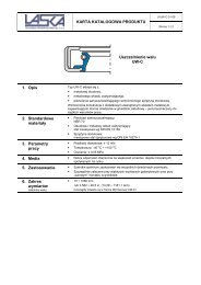
![(E) HK Normalien Aktuell [GB]](https://img.yumpu.com/48932549/1/184x260/e-hk-normalien-aktuell-gb.jpg?quality=85)