Montageanleitung 15-P-Steckdose 24 V ISO 12098 mounting ...
Montageanleitung 15-P-Steckdose 24 V ISO 12098 mounting ...
Montageanleitung 15-P-Steckdose 24 V ISO 12098 mounting ...

Create successful ePaper yourself
Turn your PDF publications into a flip-book with our unique Google optimized e-Paper software.
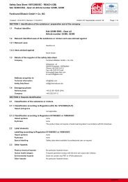
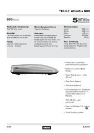
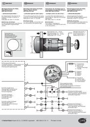
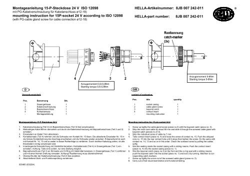
<strong>Montageanleitung</strong> <strong>15</strong>-P-<strong>Steckdose</strong> <strong>24</strong> V <strong>ISO</strong> <strong>12098</strong>mit PG-Kabelverschraubung für Kabelanschluss ø12-18)<strong>mounting</strong> instruction for <strong>15</strong>P-socket <strong>24</strong> V according to <strong>ISO</strong> <strong>12098</strong>(with PG-cable gland screw for cable connection ø12-18)HELLA-Artikelnummer: 8JB 007 <strong>24</strong>2-011 ®HELLA-part number: 8JB 007 <strong>24</strong>2-011Anzugsmoment 5-6NmStarting torque 5-6NmAnzugsmoment 0,6-0,8NmStarting torque 0,6-0,8NmVerpackungsinhalt:content of packaging:Pos. Benennung Stk.Pos. title quantity1 Dosengehäuse 1 1 socket casing 12 Kabelverschraubung 1 2 cable gland screw 13 Bajonettverschluss 1 3 bayonet catch 14 Kontakteinsatz 1 4 contact insert 1- <strong>Montageanleitung</strong> 1 - <strong>mounting</strong> instruction 1<strong>Montageanleitung</strong> <strong>15</strong> P <strong>Steckdose</strong> <strong>24</strong> V1. Kabelverschraubung (Teil 2) mit Bajonettverschluss (Teil 3) fest verschrauben.2. Mehradriges Kabel 60mm abmanteln und durch die Kabelverschraubung mit Bajonettverschluss (Teil 2 und 3)schieben.3. Einzeladern an Kabel 7mm abisolieren.4. Kontakteinsatz (Teil 4) nehmen und die Schraube von Kontakt Nr. <strong>15</strong> lösen. Die abisolierte Einzelader Nr. <strong>15</strong> indie hintere Kontaktbohrung bis Anschlag einschieben und die Schraube wieder anziehen. Entsprechend ist auchmit Kontakt Nr. 14, 13 und so weiter in dieser Reihenfolge zu verfahren. Durch leichten Kabelzug prüfen, ob alleEinzeladern richtig verschraubt sind.5. Innenliegende Dosendichtung mit Gleitmittel benetzen. Kontakteinsatz (Teil 4) in Dosengehäuse (Teil 1) einschieben.Achtung: Teile sind codiert, nur eine Stellung möglich.6. Bajonettverschluss (Teil 3) an Stirnseite und O-Ring mit Gleitmittel benetzen, in Dosengehäuse (Teil 1) einführenund mit einer kleinen Drehung verrasten. Achtung! Rastkennung muss übereinstimmen.7. Überwurfmutter der Kabelverschraubung (Teil 2) fest anziehen.8. Abschließend Sicht- und Funktionsprüfung vornehmen.035465 (030204)Mounting instruction for <strong>15</strong> pin socket <strong>24</strong> V1. Screw up tightly the cable gland screw (piece no.2) with the bayonet catch (piece no. 3).2. Strip the multi-core cable by about 60 mm and slide it through the screwed cable gland withbayonet catch (pieces no.2+3).3. Strip the individual cores of cable by 7 mm.4. Take contact insert (piece no. 4) and loose the screw of contact no. <strong>15</strong>. Push the strippedcore no. <strong>15</strong> into the rear contact hole until it stops then tigthen the screw. Do the same withcontact no. 14, 13 and so on in this order. Check the screwed cores by pulling the cablessoftly.5. Wet the sealing inside the socket casing with a sliding means. Push the contact insert(piece no. 4) into the socket casing (piece no. 1).6. Wet the bayonet catch (piece no.3) at the front and the o-ring seal with a sliding means;push the bayonet catch into the socket (piece no. 1) and lock it by turning. Attention to correspondingcatch-markers.7. Screw up tightly the union nut of the screwed cable gland (piece no. 2).8. Carry out a final visual examination and functional testing.
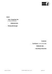
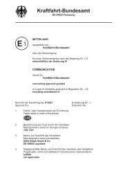
Kontaktbelegung für <strong>15</strong>-polige Steckvorrichtung <strong>24</strong> Volt nach <strong>ISO</strong> <strong>12098</strong>Contact allocation for <strong>15</strong>-pole connectors <strong>24</strong>V according to <strong>ISO</strong> <strong>12098</strong>Kontakt-Nr.ContactdesignationnumberFarbe derAderisolationCore insulationcolourKontaktbelegungContact AllocationLeiter-Nennquerschnittder AnhängerleitungNominal cross-sectionalarea of cable connectedNr./No. Farbe/colour Stromkreis Circuit mm 21 gelb/yellow Fahrtrichtungsanzeiger links Left-hand direction indicator light2 grün/green Fahrtrichtungsanzeiger rechts Right-hand direction indicator light 1,53 blau/blue Nebelschlußleuchte Rear fog light4 weiß/white Masse Common return 2,55 schwarz/black Linke Schluß-, Umriß-,Begrenzungsleuchtenund Kennzeichenbeleuchtung *)6 braun/brown Rechte Schluß-, Umriß-, Begrenzungsleuchtenund Kennzeichenbeleuchtung *)7 rot/red Bremsleuchten Stop-lights8 rosa/pink Rückfahrleuchte Reversing lightsLeft-hand rear position, marker lights and rearregistration-plateillumination device *)Right-hand rear position, marker lights and rearregistration-plateillumination device *)9 orange/orange Stromversorgung (+<strong>24</strong>V) Power supply (+<strong>24</strong> V) 2,510 grau/grey Sensor für Bremsbelagverschleißanzeige Warn brake lining sensor11 weiß-schwarzwhite-blackAnzeige für FederspeicherbremsePressure sensor for spring brake12 weiß-blau AchsanhebungAxle lifting devicewhite-blue13 weiß-rotwhite-red14<strong>15</strong>weiß-grünwhite-greenweiß-braunwhite-brownMasse für Datenleitung Common return for data lines 2,5CANHCANLCANHCANL 1,51,51,5*) Die Kennzeichenbeleuchtung mußso angeschlossen werden, daß keineLampe dieser Beleuchtung mit beidenKontakten Nr. 5 und Nr. 6 verbunden ist.*) The rear-registration-plate illumination deviceshall be connected in such a manner that nolamp of such a device is connected to both contactsnos. 5 and 6.© Hella KGaA Hueck & Co., D-59552 Lippstadt 460 918-05 2003-03-25®