Application Specific Measurement Processes<strong>Automated</strong> <strong>Assembly</strong> using 3D point networks andthe <strong>Leica</strong> Geosystems 6DoF MAP SystemAs we have already started to describe some ideasregarding wing to body stations lets continue on thistopic. We will not spend too much time on the 3Dpoint network process for these automated assemblyprocesses due to the fact that they are fairly well knownand accepted, as well as the fact that we have alreadydetailed the two “front end” control software possibilities.Instead, we will describe a hybrid combinationof 3D point based assembly with the addition of 6DoFreal-time tracking that creates the <strong>Leica</strong> Geosystems<strong>Metrology</strong> <strong>Assisted</strong> Positioning, or MAP system. Theproposed <strong>Leica</strong> Geosystems 6Dof MAP system couldcut the standard MAA joining times by as much as athird, or at least a quarter. In a standard application aLaser Tracker would have to measure a network of between6 – 8 points on the wing, plus a series of pointson the body. This process would typically take between30 to 40 seconds to complete. However, it is not themeasurement time that slows this process down. Thelimiting factor is the time that it takes to move the Jigsand re-measure the parts in an iterative process.If we concentrate on a single wing (above) then thetime required to move this wing into position couldtake up to 45 minutes for just the measurements. Thisis assuming roughly 5 seconds per point for positioningand measurement of the Laser Tracker, and between 10– 15 iterations to bring the wing into the final alignmentposition. In comparison, using the same wing, but thistime rather than calculating the positioning deltas froma network of points, we’ll use the <strong>Leica</strong> Geosystems6DoF MAP System to track the wing in real-time. The6DoF MAP system consists of a <strong>Leica</strong> T-Mac in combinationwith a <strong>Leica</strong> Absolute Laser Tracker and T-Cam.The <strong>Leica</strong> T-Mac is attached to the part that needs to bealigned (in this case the wing), and the 6DoF deltas arefed back in real-time directly to the wing positioners.The <strong>Leica</strong> T-Mac has the same 3D positional uncertaintyof a standard Laser Tracker measurement, but alsogeneratesPage 9 of 15 pitch, roll, and yaw angles. The 2 Sigmaangular uncertainty is 0.01° so long as the <strong>Leica</strong> T-Macis mounted no more than 6 meters from any edge ofthe mating surface, the achievable accuracy along thissurface is equal to about 1.0mm (where Δb = Sin * Radius).This allows for a very flexible setup process wherethe <strong>Leica</strong> T-Mac could even be placed meters above thewing for extremely easy line of sight requirements.◄ ►► ◄>2m>2mThe communication from the <strong>Leica</strong> T-Mac position tothe wing positioners is a direct feedback loop to keepthe data latency as low as possible. This helps to positionthe wing with the maximum amount of time savings.In order to guarantee that the wing never touchesthe body during the MAP process, a positive gap of5mm should be maintained. This is roughly equal to adoubling of the 6H uncertainty of the <strong>Leica</strong> T-Mac rotationangles at these distances (e.g. 6 meters).Once the <strong>Leica</strong> Geosystems 6DoF MAP system finishes,and the wing is within 5mm of its final location, thenthe standard process of measuring the fixed reflectorsand calculating the best-fit positioning for the finallocation should start. This process should run as itdoes with the other Aerospace FAL processes that arealready proven out. Whether the process is controlledfrom an external Application Process Manager or froman integrated metrology package is inconsequential toour overall solution. The main differences would be thatif it is implemented in an integrated metrology package(e.g. Spatial Analyzer, or Metrologic), all parts ofthe communication would need to be integrated by thismetrology software. If however it is implemented asa measurement process in the Measurement ProcessManager it could use the functionality that is integratedin the MPM (e.g. transformations, bundle, etc…) andcommunicate directly with the <strong>Assembly</strong> Process Managerthat is controlling the wing positioners.8 Application Specific Measurement Processes
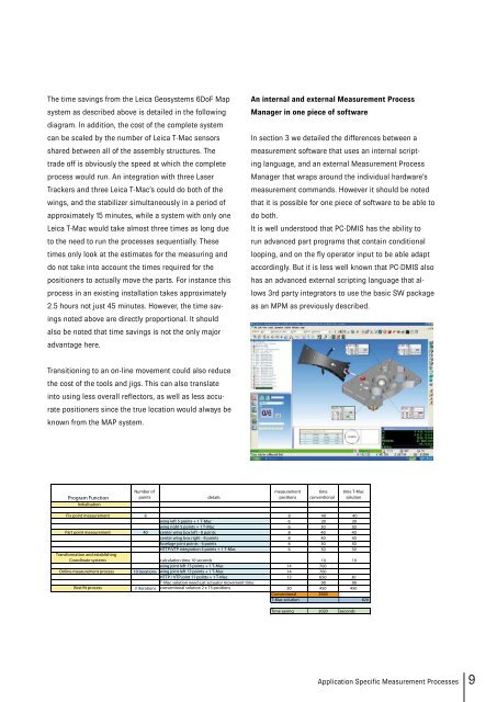
The time savings from the <strong>Leica</strong> Geosystems 6DoF Mapsystem as described above is detailed in the followingdiagram. In addition, the cost of the complete systemcan be scaled by the number of <strong>Leica</strong> T-Mac sensorsshared between all of the assembly structures. Thetrade off is obviously the speed at which the completeprocess would run. An integration with three LaserTrackers and three <strong>Leica</strong> T-Mac’s could do both of thewings, and the stabilizer simultaneously in a period ofapproximately 15 minutes, while a system with only one<strong>Leica</strong> T-Mac would take almost three times as long dueto the need to run the processes sequentially. Thesetimes only look at the estimates for the measuring anddo not take into account the times required for thepositioners to actually move the parts. For instance thisprocess in an existing installation takes approximately2.5 hours not just 45 minutes. However, the time savingsnoted above are directly proportional. It shouldalso be noted that time savings is not the only majoradvantage here.An internal and external Measurement ProcessManager in one piece of softwareIn section 3 we detailed the differences between ameasurement software that uses an internal scriptinglanguage, and an external Measurement ProcessManager that wraps around the individual hardware’smeasurement commands. However it should be notedthat it is possible for one piece of software to be able todo both.It is well understood that PC-DMIS has the ability torun advanced part programs that contain conditionallooping, and on the fly operator input to be able adaptaccordingly. But it is less well known that PC-DMIS alsohas an advanced external scripting language that allows3rd party integrators to use the basic SW packageas an MPM as previously described.Transitioning to an on-line movement could also reducethe cost of the tools and jigs. This can also translateinto using less overall reflectors, as well as less accuratepositioners since the true location would always beknown from the MAP system.Application Specific Measurement Processes 9