PA C history - PAC World magazine
PA C history - PAC World magazine
PA C history - PAC World magazine
- No tags were found...

Create successful ePaper yourself
Turn your PDF publications into a flip-book with our unique Google optimized e-Paper software.
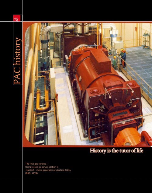
70<strong>PA</strong>C <strong>history</strong>History is the tutor of lifeThe first gas turbine –Compressed air power station inHuntorf - static generator protection GSX6(BBC, 1978)
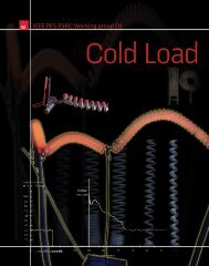
A program to introduce"multifunction generatorprotection system" (MGPS)was started in the US in 1987.6 Static generator protection GSX6, BBC, 197873with different modules. E.g. S<strong>PA</strong>G331B (Figure 11) withunit SPCP3B2, a combined single-stage reverse power andtwo-stage overvoltage relay module with definite timecharacteristic, SPCJ3C3, a two-stage overcurrent relay modulewith a definite time, or an IDMT low-set and an instantaneousor definite time high-set stage and SPCU1C6, a two-stage,definite time neutral displacement voltage , measuringovervoltage relay module with definite time characteristic.The first numerical generator protection was developedby BBC in 1987 (Figure 9a/b) using Intel's 16-bit-processor80186 (10 MHz). The scheme of the REG200 series is shownin Figure 12.At the end of the 1980's BBC/ABB's Modures-Series(REG100, 110, 216 and 316) were produced. REG216 wasequipped with more than 36 analogue inputs and utilized theprotection functions ANSI (59N) (64) (87G) (87T) (50/51)(49) (64R) (59) (27) (81) (32) (46) (59) (59R) and (51/27).To increase availability and to achieve redundancy twoplug-in systems could be combined (REG110 and REG150 asshown in Figure 10. The main protection functions have beenidentical, short circuit protection was realized as follows:REG110 with minimum impedance protectionREG150 with high impedance differentialprotectionThe COMBIFLEX system, was developed by ABB in 1990,where single devices could be combined into groups. Figure 13shows a typical apparatus group. An overview of protectionfunctions in COMBIFLEX is shown in table 2.SIEMENS proposed their new concept for generatorprotection with the digital machine protection 7UM5 in4 MSTAB, ELIN, 1979Microprocessor stability relay5 MC91, BBC, 1984,Microprocessor controlled overcurrentrelay7 Trip matrix 7TA2, Siemens, 1984,8 Typical Protection for a Large or ImportantGenerator, IEEE, 1998870MGPS #1Relaying Functions242732-132-24046495051 V/2150 /51N608187G27TN or 59D87 T GENTransf87 AT78GENUtility64FMGPS #1Relaying Functions242732-132-24046495051 V/2150 /51N608187G27TN or 59DAUXBUS<strong>PA</strong>C.DECEMBER.2011
74<strong>PA</strong>C <strong>history</strong>10 REG110 & REG150 combined, ABB, 1993 The COMBIFLEX systemwas developedby ABB in 1990.table 2 Examples of protection functions inCOMBIFLEX, ABB, 2006Function Protection Comment ANSI9 GeneratorprotectionREG216(BBC, 1987)a1992 (Figure 17). The protection devices required for smallmachines, unit machines with medium and big power isshown in Figure 15. The relays 7UM511, 7UM512 and7UM515 provide different functionalities which can replaceeach other and allows redundant usage.Beckwith Electric produced its microprocessor-basedgenerator protection relay M-3430 that uses digital signalprocessing with 15 protective relaying functions since 1993(Figure 16).GEC's MIDOS contains protection relays as shown inFigure 14. The fully digital DRS system of ELIN was used at100% stator E/F RAGEK 59N/27NUnderexcitation I RAGPK 40Underexcitation II RAPDK RXPDK 21H 40Rotor E/F RAHL + Injection unit RXTTE 4Rotor E/F I RAPDK + Injection unit RXTTE 4 64R-DC sideNegative seq. Overcurrent RAIIK 46Diode failure RAIDK RXIDK 2H standardDead machine protection RAGIK 50/27Reverse power RAPPK 32Stator DifferentialRADSCRADHA87GBlock Differential RADSB 87T & TCTurn Differential RAIDK or RAEDK 59N or 50NTurn DifferentialRAIF/RAEGRestricted E/FRADHD High impedance E/F 87NRAPDK Active E/F current 87NSelective E/F RAIG Sensitive E/F diff. 87NBearing current RARIC o.4 - 1 ASwiss Rail (SBB) in 1995 for the first time.This was the same year when AEG came out with digitalgenerator protection PG851 and PG871 (Figure 22). Later,the additional relay PG811 was used (Figure 23). As it waswith the other vendors, the protection functions were moreor less distributed and redundant. The 90%-stator earth faultprotection (67N) was included in PG851; the 100%-functionwas a part of the PG781 (with 20Hz-measurement). Rotorearth fault was implemented in PG811.Generators bigger than 100 MVA have been equippedwith PG871 as main and with PG851 as backup-protection.REG216 -Schemeb11 Generator protection relays S<strong>PA</strong>G331B,ABB, 199212 Numerical protection REG200-Series, ABBAnalog busU R' U S' U T' U 0IU R' I RR' I S' I T' I I 0R' I S' I T I RE' I RE23 4MMC53I >3U >3U
75Smaller generators worked with one or two PG851. One ofthe first applications was IKW Staßfurt (Germany) with 350-MVA-units, 10/110 kV and the power station CukrowniaLubna in Poland. GE's digital generator protection relay wasproduced in 1997- the functions are visualized in Figure 18and Figure 25. Additionally in 1997 GE presented the SR489generator management relay with additional backup andmonitoring functions (Figure 21).Beckwith Electric's Integrated Protection Systems forgenerators M-3425 is shown in Figure 26.SEL's 300-G (Figure 28) came out in 1998, the functionsare in Figure 29.Chinese SIFANG produced digital unit protection CST30Ain 1999 (for huge generators).Since 2001 GE produces Generator Management RelayG60 (Figure 27) and G30 as Combined Generator andTransformer Protection. Developing the EUROPORT-Series(2005) Protecta (Hungary) presented Digital Generator andGenerator-Transformer Unit Protection DGBV-EP (Figure19). SEL's 700-series (2010) contains Intertie and GeneratorProtection Relay SEL-700G (Figure 20).A further development of SIEMENS SIPROTEC (in 2000)was a redundant protection concept for bigger generators withunit transformers utilizing 7UM6 and 7UT6 (Figure 24).ABB's new series 670 (2007) also contain a generatorprotection IED REG670.Finally I want to remind you, that for conventional as well asfor static protection in the past for instance in 500-MW-unitsat least 12 cubicles were used. During the transition period itwas common, to have 2 times static relays (e.g. system 1 andsystem 2- Boxberg Germany) or, later, two have a static and adigital system (Schwarze Pumpe Germany).Testing technology and the generations should be coveredin a later article.14 Generator protection MIDOS, GEC, 1995Gsmallmachine7UM511GMVAJ23TrippingrelayMBCH12MRSUO1 MVTU18 METI11Neutral Directionaldisplacement relayRotor earth relayfault relayStator earth fault prot.MCND01Negativephasesequence(unb. relayMYTU01Fieldfailurerelay* MMLG01 Test blockMBCH12MVTU11 MVTU12 MFVU21UndervoltagvoltageunderOver-Over andfrequencyVoltage protection relay7UM5117UM5127UT512MRSU01VoltagerestrainedovercurrentrelayMWTU01ReversepowerrelayMBCH12Biased differential protection15 Protection concept utilizing 7UM5 and7UT5, Siemens, 1992abunit machinemediumGfor hugeunits16 Generator protection relay M-3430,Beckwith Electric, 1993c7UM5127UT5127UT5127UM5117UM5117UM5127UT5127UT515walter.schossig@pacw.orgwww.walter-schossig.de13 COMBIFLEX, a typical apparatus group,ABB, 199017 Machine protection relay7UM515, Siemens, 199418 DGP, GE, 1997<strong>PA</strong>C.DECEMBER.2011
76<strong>PA</strong>C <strong>history</strong>21 Generator management relay SR489,GE, 1997CombinedGenerator andTransformermanagementrelay SR489.25 Single line diagram DGP, GE, 199751GN 27NT64G2 64G1RS232ToModemGRS232ToLaptopPCAlarmTripGSUTrans.52G87G VTFF 51V 32 40 46 24 64G2 32 27 81VTFF 51V 32 40ToPowerSystemDGP22 Digital generator protection PG851and PG871, AEG, 199526 Front panel M-3425, Beckwith Electric,199819 DGBV-EP,Protecta, 2005(Generator - transformerunit relay )27 Generator management relay G60, GE,200123 Generator protection- additional relayPG811, AEG28 SEL-300G, SEL, 199820 SEL-700G,SEL, 2010(Intertie and GeneratorProtection Relay)24 Redundant concept with SIPROTEC,Siemens, 2000BP7UM622I REF U REF I2 L U exc U M U contr U L I L7XT71U DC U 0 I2 L U exc T I1 L U L7UM622Protection group 1Protection group 2G7UT6x3I3 L I2 L IE 1 I1 LSystem52 527UM612U LU 0I L U 0 U L I L7UT6x2 7SA611(option)I1 LI2 L52Auxiliary switchgear29 Functions of SEL-300G, SEL, 1998Bus52312 or 3SEL-2664SEL-2664311SEL-300G Relay*59 p GQ overcurrent-phase*Volts-per--ground 87Hertz-neg.*24 25 27 59 p seq. frequencyG 81 o Q U*64Ffieldground49Thermal32Synchrocheckcurrentdifferentialneutraltimeovercurrentground timeovercurrenpotentialLoss-of-78 40 46 50 p G 51G 21p/c21v/c 60directional out-Loss-Neg. overcurrent phasepower of-step field over--ground64Gof-seq. -phase Mhocurrent**neutral 100%50N 51N 87N overvoltage statorgroundneutralneutral current 59Novercurrentdifferentialundervoltage-phaseovervoltage-ground-neg. seq.SELogic ControlEquationsEvent reportsSequential eventsrecorder (SER)Breaker Wear MonitorStation Battery MonitorModbus, ASCII, Fast SER,Binary, & Distributedport switchcommunicationsRemote & controlswitchesHigh-accuracy meteringOff-frequency operationtime accumulatorsField ground detection* Optional functions* * Provided when 87is not selected<strong>PA</strong>C.DECEMBER.2011