J-bolt Lip and Wing Shrouds - March 2011 - Hensley Industries, Inc.
J-bolt Lip and Wing Shrouds - March 2011 - Hensley Industries, Inc.
J-bolt Lip and Wing Shrouds - March 2011 - Hensley Industries, Inc.
- No tags were found...

Create successful ePaper yourself
Turn your PDF publications into a flip-book with our unique Google optimized e-Paper software.
J-BOLT LIP & LOWER WING SHROUD PARTSLS130-1700JSTD LS130-1700J*LS130-2350J LS800-2200JLIP SHROUDSPART NO.WELDBASEJ-BOLTASSEMBLYLBS.WEIGHTKGS.LS130-1700JSTD735.0 333.7LS130-1700J* 840.0 381.4LSWB9SFA150J6LS130-2350J 895.0 406.3LS800-2200J 962.0 436.7*optional heavy duty shroudSFA150J6LSWB9LSWB10WS135L (LH shown) WS135R (RH opposite)LOWER WING SHROUDSPART NO.WELDBASEJ-BOLTASSEMBLYSIDE PLATETHICKNESSLBS.WEIGHTKGS.12WS135L280.0 127.0LSWB10 SFA150J6 5.32 IN. 135 MMWS135R 280.0 127.0
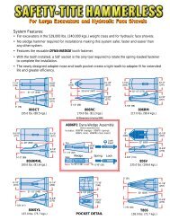
J-BOLT LIP SHROUD INSTALLATIONBEFORE STARTING INSTALLATION, BE SURE TO READALL INSTRUCTIONS THOROUGHLY!STEP 1NEW INSTALLATIONREPLACEMENT INSTALLATIONfig. 1-1 fig. 1-11 a) Slide weld base into back of lip shroud.1 b) Position the shroud on the cast lip makingsure that the blunt throat surface of the shroud“X" contacts the blunt front surface of the lip “Y".There should be no contact between the bevel ofthe shroud <strong>and</strong> area "Z" of the cast lip(fig. 1-1).NOTE: This contact must be maintainedthroughout the assembly process to insure theproper location of the weld base.Grind the top surface of the lip material that will beaffected by weld. Insure all carbon slag or otherimpurities from the removal of the old base areground out. The use of non-destructive testing atthis point will help determine if there are any crackspresent in the base material. Repair base materialas needed. (Now proceed as with new installation.)1 a) Slide weld base into back of lip shroud.1 b) Position the shroud on the cast lip makingsure that the blunt throat surface of the shroud“X" contacts the blunt front surface of the lip “Y".There should be no contact between the bevel ofthe shroud <strong>and</strong> area "Z" of the cast lip (fig. 1-1).NOTE: This contact must be maintainedthroughout the assembly process to insure theproper location of the weld base.13
J-BOLT LIP SHROUD INSTALLATIONSTEP 2Align the back of the Weld base so that it is flushwith the back of shroud (fig. 2-1).fig. 2-1STEP 3After placement of weld base has been confirmed,<strong>and</strong> tack weld the base at the rear along weld prepsurface “A" (fig.3-1).fig. 3-1SPECIAL NOTESRecommended filler material: AWS specification A5.1, class E7018 stick electrode. Stick electrodes shouldbe kept in a heated rod oven at 250 O F / 120 O C prior to use.NOTE: See manufacturer's recommended procedures for storage <strong>and</strong> preservation of low hydrodgen electrodes.Recommended weld types:Stringer beads are recommended for higher strength <strong>and</strong> less distortion.The use of weave or wash beads in NOT recommended <strong>and</strong> should not beused. Arc strikes should be avoided or ground down.14
J-BOLT LIP SHROUD INSTALLATIONSTEP 4Remove the shroud <strong>and</strong> prepare to weld-out thebase by establishing a preheat temperature of300 O F / 150 O C to 450 O F / 230 O C for the basematerial (fig. 4-1). Maintain this temperaturethroughout the weldingprocess.STEP 5fig. 4-1Weld-out for the base should begin with theinner legs of base. A 1/2" (13mm) fillet weld shouldbe deposited in this area (fig. 5-1).BE SURE THAT THE ENTIRE BOTTOM SUR-FACE OF THE WELD BASE MAINTAINS CON-TACT WITH THE LIP DURINGENTIRE WELD-OUT PROCESS.fig. 5-115
J-BOLT LIP SHROUD INSTALLATIONSTEP 6fig. 6-1Apply weld to the base perimeter next. Utilizinggroove welds, fill the 1.0" (25mm) weld grooveon the base completely (fig. 6-1 & fig. 6-2). Caremust be taken at this point not to add too muchweld. If joint is over welded, the weld material caninterfere with the lip shroud. The idea is to add asmuch weld as possible to the base without causinginterference with the lip shroud (fig. 6-3). Whenthe welding process has been completed, allow aslow cool down period to ambient temperature. Acool down rate of no greater than 35 O per hour isrecommended.fig. 6-2fig. 6-3STEP 7Before repositioning the shroud on the lip, insertthe J-<strong>bolt</strong> into the shroud through the top hole(fig. 7-1). Rotate the <strong>bolt</strong> 90 o so that the threadedend is facing the rear of the shroud.fig. 7-116
LOWER J-BOLT WING SHROUD INSTALLATIONBEFORE STARTING INSTALLATION, BE SURE TO READALL INSTRUCTIONS THOROUGHLY!STEP 1NEW AND REPLACEMENT INSTALLATIONfig. 1-1NEW INSTALLATIONPosition the wing shroud on cheek plateportion of the cast lip making sure that theblunt throat surface of the shroud "X" contactsthe blunt front surface of the cheek plate "Y". Theshroud should be positioned so that there isapproximately a 1" (25mm) gap between the bottomof the shroud <strong>and</strong> the intermediate adapter.(fig. 1-1).NOTE: This contact <strong>and</strong> gap must be maintainedthroughout the assembly process to insure theproper location of the weld base.FOR 201" LIP - The angle of the blunt front surfaceof the cheek plate "Y" differs from the 163" & 169"lips.The shroud should still be positioned so thatthere is approximately a 1" (25mm) gap betweenthe bottom of the shroud <strong>and</strong> the intermediateadapter (fig. 1-1).18REPLACEMENT INSTALLATIONGrind the outside portion of the cheek plate areaof the cast lip that will be affected by weld. Insureall carbon slag or other impurities from the removalof the old base are ground out. The use of nondestructivetesting at this point will help determineif there are any cracks present in the base material.Repair base material as needed. (Now proceed aswith new installation.)Position the wing shroud on cheek plate portionof the cast lip making sure that the blunt throatsurface of the shroud “X" contacts the blunt frontsurface of the cheek plate “Y". The shroud shouldbe positioned so that there is approximately a1" (25mm) gap between the bottom of the shroud<strong>and</strong> the intermediate adapter. (fig. 1-1).NOTE: This contact <strong>and</strong> gap must be maintainedthroughout the assembly process to insure theproper location of the weld base.
LOWER J-BOLT WING SHROUD INSTALLATIONInsert the weld base as shown into the rear of thewing shroud until it is flush with the rear of the wingshround (fig. 2-1 - fig. 2-2)STEP 2fig. 2-1fig. 2-2STEP 3After placement of weld base has been confirmed,Pre-heat the base material to 300 O F / 150 O C to450 O F / 230 O C <strong>and</strong> tack weld the base at the rearalong weld prep surface “A" (fig.3-1).fig. 3-119
LOWER J-BOLT WING SHROUD INSTALLATIONSTEP 6Apply weld to the base perimeter next. Utilizinggroove welds, fill the 1.0" (25mm) weld grooveon the base completely (fig. 6-1 & fig. 6-2). Caremust be taken at this point not to add too muchweld. If joint is over welded, the weld material caninterfere with the lip shroud. The idea is to add asmuch weld as possible to the base without causinginterference with the lip shroud (fig. 6-3). Whenthe welding process has been completed, allow aslow cool down period to ambient temperature. Acool down rate of no greater than 35 O per hour isrecommended.fig. 6-1 fig. 6-2 fig. 6-321
LOWER J-BOLT WING SHROUD INSTALLATIONSTEP 7Before repositioning the shroud on the cheekplate, insert the J-<strong>bolt</strong> into the shroud through thetop hole (fig. 7-1). Rotate the <strong>bolt</strong> 90 o so that thethreaded end is facing the rear of the shroud.fig. 7-1STEP 8Reposition the shroud on the cheek plate by slidingit onto the weld base as far as it will go, once again,making sure surface “X" contacts surface “Y"(fig. 8-1).fig. 8-1STEP 9Install the washer, spring, collar assembly <strong>and</strong> thenuts in the order indicated for J-<strong>bolt</strong> assembly typeJ6 (fig. 9-1), Torque locking nuts to 300 ft. lbs /407 Nm.[NOTE: the locking nut cannot beh<strong>and</strong>-threaded onto the J-<strong>bolt</strong>]fig. 9-1SPECIAL NOTE: For best results, it may be necessary to re-torque all fastener componentsperiodically depending on the application. Usually, re-torquing componentsafter a few hours of machine operation will insure component security22
LOWER J-BOLT WING SHROUD INSTALLATIONJ-BOLT SHROUD SEATING AND MAINTENANCE INSTRUCTIONSSEATING FOR NEW INSTALLATIONIt is normal that the shrouds migrate back slightly with the force of the machine.Therefore, it is recommended that the following procedure be followed to ensure proper seating of the shrouds.Instructions:1. Run machine for 10 non-production cycles.2. Remove 2 nd locking nut from shroud installation.3. Re-tighten the 1 st locking nut for any movement.4. Re-install 2 nd locking nut5. Release machine for production.Note: if the first nut on any installation is excessively loose, then repeat this procedure.RETIGHTENING AND MAINTENANCECheck <strong>and</strong> retighten the nuts after 6 hours of service, then after 24 hrs. Generally, nuts should be periodicallychecked after 750 to 1000 hrs. In extreme conditions, <strong>and</strong> 1500 to 2000 hrs. In moderate conditions, or by thefrequency dictated by your specific application.23
SAFETY FIRST: <strong>Hensley</strong> recommends that you use a soft-faced hammer <strong>and</strong> ANSI-approved (Z87.1) eye protection while using our products.88<strong>Hensley</strong> <strong>Industries</strong>, <strong>Inc</strong>.888 406 - 6262 U.S./Canada+1 972 406 - 6262 all other locations<strong>Hensley</strong> Attachments800 433 - 3144 U.S./Canada+1 817 477 - 3167 all other locationswww. hensleyind.comCopyright © <strong>2011</strong> <strong>Hensley</strong> <strong>Industries</strong>, <strong>Inc</strong>.This publication is protected under the copyright laws of the United States. Unauthorized duplication or distribution is prohibited.CAST LIP OWNER'S MANUAL JAN <strong>2011</strong>