Bolt-on Wear Runners - March 2011 - Hensley Industries, Inc.
Bolt-on Wear Runners - March 2011 - Hensley Industries, Inc.
Bolt-on Wear Runners - March 2011 - Hensley Industries, Inc.
- No tags were found...

Create successful ePaper yourself
Turn your PDF publications into a flip-book with our unique Google optimized e-Paper software.
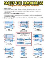
BOLT-ON WEAR RUNNER PARTSB12X9WRweld runnerBOLT-ON WEAR RUNNERPART NO.WELDBASENUT/BOLTASSEMBLYLBS.WEIGHTKGS.B12X9WR 12X9B 115BN 49.0 22.212X9Bweld base42exploded view ofbolt-<strong>on</strong> wear runnerand hardware
BOLT-ON WEAR RUNNER INSTALLATIONBEFORE STARTING INSTALLATION, BE SURE TO READALL INSTRUCTIONS THOROUGHLY!STEP 1Topside Installati<strong>on</strong> behind wear caps.Positi<strong>on</strong> the wear runner weld base behind the wear cap. Place wear runner <strong>on</strong>to baseto check for clearances. There is to be a 1" (25mm) gap between the bolt-<strong>on</strong> wear capand the wear runner (fig. 1-1 - fig. 1-2).fig. 1-2fig. 1-1Underside Installati<strong>on</strong> behind intermediate adapters.Positi<strong>on</strong> the wear runner weld base behind the intermediate adaper. Place wearrunner <strong>on</strong>to base to check for clearances. There is to a 2" (50mm) gap between theintermediate adatper and the wear runner (fig. 1-3 & fig. 1-4).fig. 1-4fig. 1-343
BOLT-ON WEAR RUNNER INSTALLTIONSTEP 2Preheat area of cast lip, where the weld baseis located, between 300°F/150°C and 450 O F /230 O C. Tack weld base. Weld-out for the baseshould begin with the slot area of the base.Deposit a 1/2" (13mm) fillet weld, all the wayaround (fig. 2-1)fig. 2-1STEP 3fig. 3-1Apply weld to the base perimeter next. Depositstringer beads to fill the groove <strong>on</strong> the basecompletely. Care must be taken at this point notto add too much weld. If the joint is over welded,the excess weld material can interfere with theinstallati<strong>on</strong> of the wear Runner (fig. 3-1 - fig 3-3).Note: When the welding process has beencompleted, cool with insolating blankets for a slowcool down.fig. 3-2fig. 3-344
BOLT-ON WEAR RUNNER INSTALLTIONInsert the wear runner bolts into the bolt slots of thebase and place the wear runner <strong>on</strong>to the weld base(fig. 4-1). Install nuts <strong>on</strong>to the bolts and torque to300 ft-lbs. (406.8 Nm) (fig. 4-2).STEP 4fig. 4-1fig. 4-245
46THIS PAGE INTENTIONALLY LEFT BLANK
SAFETY FIRST: <strong>Hensley</strong> recommends that you use a soft-faced hammer and ANSI-approved (Z87.1) eye protecti<strong>on</strong> while using our products.88<strong>Hensley</strong> <strong>Industries</strong>, <strong>Inc</strong>.888 406 - 6262 U.S./Canada+1 972 406 - 6262 all other locati<strong>on</strong>s<strong>Hensley</strong> Attachments800 433 - 3144 U.S./Canada+1 817 477 - 3167 all other locati<strong>on</strong>swww. hensleyind.comCopyright © <strong>2011</strong> <strong>Hensley</strong> <strong>Industries</strong>, <strong>Inc</strong>.This publicati<strong>on</strong> is protected under the copyright laws of the United States. Unauthorized duplicati<strong>on</strong> or distributi<strong>on</strong> is prohibited.CAST LIP OWNER'S MANUAL JAN <strong>2011</strong>