view data sheet - Electro Rent Corporation
view data sheet - Electro Rent Corporation
view data sheet - Electro Rent Corporation

Create successful ePaper yourself
Turn your PDF publications into a flip-book with our unique Google optimized e-Paper software.
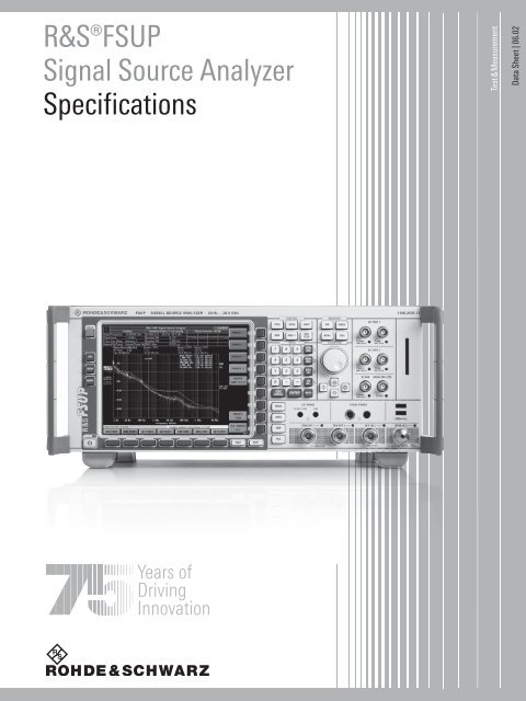
R&S®FSUPSignal Source AnalyzerSpecificationsTest & MeasurementData Sheet | 06.02
Version 06.02, February 2009CONTENTSSpecifications..............................................................................................................................................................................................3All operating modes....................................................................................................................................................................................3Signal source analyzer mode.....................................................................................................................................................................3Phase noise measurement with PLL method ...........................................................................................................................................3Phase noise measurement, PLL method without cross-correlation .........................................................................................................4Phase noise measurement, PLL method with cross-correlation ..............................................................................................................5R&S ® FSUP-B60 low phase noise option installed, R&S ® FSUP-B61 correlation extension option not installed .................................5R&S ® FSUP-B60 low phase noise option and R&S ® FSUP-B61 correlation extension option installed................................................6Phase noise sensitivity improvement by correlation.................................................................................................................................7Phase noise measurement, spectrum analyzer mode .............................................................................................................................7Amplitude noise measurement .................................................................................................................................................................7Residual phase noise measurement with external phase detector (added phase noise measurement) ................................................8Residual phase noise measurement with internal phase detector (added phase noise measurement) .................................................8Baseband noise measurement.................................................................................................................................................................8Transient measurements..........................................................................................................................................................................9VCO parameter characterization ............................................................................................................................................................10Spectrum analyzer mode..........................................................................................................................................................................12Frequency...............................................................................................................................................................................................12Sweep.....................................................................................................................................................................................................13Resolution bandwidths ...........................................................................................................................................................................13Level .......................................................................................................................................................................................................15I/Q <strong>data</strong>...................................................................................................................................................................................................19Trigger functions.....................................................................................................................................................................................19Inputs and outputs (front panel)..............................................................................................................................................................19Inputs and outputs (rear panel) ..............................................................................................................................................................20General <strong>data</strong>...........................................................................................................................................................................................22R&S ® FSUP-B21 LO/IF ports for external mixers (for R&S ® FSUP26 and R&S ® FSUP50 only) .............................................................23R&S ® FSU-B23 RF preamplifier (for R&S ® FSUP26 only, requires R&S ® FSU-B25 option)....................................................................23R&S ® FSU-B25 electronic attenuator ......................................................................................................................................................24R&S ® FSUP-Z1 AM noise detector..........................................................................................................................................................25Measurement range ...........................................................................................................................................................................25Effective system <strong>data</strong> .........................................................................................................................................................................25General <strong>data</strong> ......................................................................................................................................................................................25Ordering information ................................................................................................................................................................................26Options ...................................................................................................................................................................................................26Recommended extras ............................................................................................................................................................................272 Rohde & Schwarz R&S ® FSUP Signal Source Analyzer
Version 06.02, February 2009SpecificationsSpecifications apply under the following conditions:30 minutes warm-up time at ambient temperature, specified environmental conditions met, calibration cycle adhered to, and totalcalibration performed. Data without tolerances: typical values only unless otherwise stated. Data designated 'nominal' applies to designparameters and is not tested.Operating modesSignal source analyzersignal source analyzerspectrum analyzerphase noise measurement with spectrum analyzer methodphase noise measurement with PLL method without cross-correlationinternal referenceexternal referencephase noise measurement with PLL method with cross-correlationresidual phase noise measurementAM noise measurement 1baseband noise measurementtransient measurementsVCO parameter characterizationAll operating modesInternal reference frequencyReference frequency, internal, nominal standard OCXOAging per day after 30 days of continuous operation 1 × 10 –9Aging per year after 30 days of continuous operation 1 × 10 –7Temperature drift +5 °C to +40 °C 8 × 10 –8Total frequency error per year 1.8 × 10 –7Reference frequency, internal, nominal R&S ® FSU-B4 optionAging per day after 30 days of continuous operation 2 × 10 –10Aging per year after 30 days of continuous operation 3 × 10 –8Temperature drift +5 °C to +40 °C 1 × 10 –9Total frequency error per year 5 × 10 –8External reference frequency 1 MHz to 20 MHz, 1 Hz steps 2Signal source analyzer modePhase noise measurement with PLL method(internal reference oscillator, internal phase detector)Frequency rangeFrequency resolutionOffset frequency rangeRF level rangeLoop bandwidthR&S ® FSUP81 MHz to 8 GHzR&S ® FSUP261 MHz to 26.5 GHzR&S ® FSUP501 MHz to 50 GHz0.01 Hz1 Hz to 30 MHzInput frequency < 46 GHz>–10 dBm to +30 dBm–20 dBm to +30 dBm (typ.)Input frequency ≥ 46 GHz> 0 dBm to +30 dBm–5 dBm to +30 dBm (typ.)PLL control of internal reference 1 Hz to 10 kHz 3PLL control of DUT 1 Hz to 10 kHz 31 External AM noise detector required.2 With the R&S ® FSUP-B60 option, only 10 MHz can be used as an external reference frequency.3 Limits may vary depending on DUT tuning slope and resulting loop stability.Rohde & Schwarz R&S ® FSUP Signal Source Analyzer 3
Version 06.02, February 2009Phase noise measurement, PLL method without cross-correlation(internal reference oscillator, internal phase detector)Spurious level, internal referenceMeasurement uncertaintySpectral purity, SSB phase noise (1 Hz)Measurement modesoffset > 1 kHzf ≤ 8 GHz–80 dBc8 GHz to 16 GHz –74 dBc16 GHz to 26.5 GHz –68 dBc26.5 GHz to 50 GHz –62 dBcsignal harmonics < –30 dBc100 Hz to 10 MHz offset typ.
Version 06.02, February 2009Phase noise measurement, PLL method with cross-correlationR&S ® FSUP-B60 low phase noise option installed, R&S ® FSUP-B61 correlation extension option notinstalledFrequency rangeSpurious level, internal referenceMeasurement uncertaintyR&S ® FSUP81 MHz to 8 GHzR&S ® FSUP261 MHz to 26.5 GHzR&S ® FSUP501 MHz to 50 GHzoffset > 1 kHzf ≤ 8 GHz–80 dBc8 GHz to 16 GHz –74 dBc16 GHz to 26.5 GHz –68 dBc26.5 GHz to 50 GHz –62 dBcsignal harmonics ≤ –30 dBc100 Hz to 10 MHz offset typ.
Version 06.02, February 2009R&S ® FSUP-B60 low phase noise option and R&S ® FSUP-B61 correlation extension option installedFrequency rangeSpurious level, internal referenceMeasurement uncertaintyR&S ® FSUP261 MHz to 26.5 GHzR&S ® FSUP501 MHz to 50 GHzoffset > 1 kHzf ≤ 8 GHz–80 dBc8 GHz to 16 GHz –74 dBc16 GHz to 26.5 GHz –68 dBc26.5 GHz to 50 GHz –62 dBcsignal harmonics < –30 dBc100 Hz to 10 MHz offset typ.
Version 06.02, February 2009Phase noise sensitivity improvement by correlationNominal phase noise sensitivity improvement by correlation measurementsNumber of correlations 10 100 1000 10000Phase noise sensitivity improvement by up to 5 dB 10 dB 15 dB 20 dBPredefinedcorrelation modesOffset frequencyrangemode "fast" mode "normal" mode "averaged"number ofcorrelationsimprovementby up to(nominalvalues, in dB)number ofcorrelationsimprovementby up to(nominalvalues, in dB)number ofcorrelations1 Hz to 3 Hz 1 0 1 0 3 23 Hz to 10 Hz 1 0 3 2 10 510 Hz to 30 Hz 1 0 10 5 30 730 Hz to 100 Hz 1 0 30 7 100 10100 Hz to 300 Hz 1 0 100 10 100 10300 Hz to 1 kHz 3 2 100 10 300 121 kHz to 3 kHz 10 5 100 10 300 123 kHz to 10 kHz 30 7 100 10 1000 1510 kHz to 30 kHz 100 10 100 10 1000 1530 kHz to 100 kHz 100 10 100 10 1000 15100 kHz to 300 kHz 100 10 300 12 1000 15300 kHz to 1 MHz 100 10 300 12 1000 151 MHz to 3 MHz 100 10 300 12 1000 153 MHz to 10 MHz 100 10 300 12 1000 1510 MHz to 30 MHz 100 10 1000 15 3000 17Phase noise measurement, spectrum analyzer modeimprovementby up to(nominalvalues, in dB)Frequency rangeDisplayed average noise levelPhase noise sensitivityR&S ® FSUP81 MHz to 8 GHzR&S ® FSUP261 MHz to 26.5 GHzR&S ® FSUP501 MHz to 50 GHzspecifications under "Displayed average noise level" in section "Spectrum analyzermode" applyspecifications under "Spectral purity, SSB phase noise" in section "Spectrum analyzermode" applyAmplitude noise measurementFrequency rangeR&S ® FSUP8, R&S ® FSUP26,R&S ® FSUP50frequency range depends on external AMnoise detector rangeInput voltage at Input 2 connector max. ±1 V (V rms )Input impedance at Input 2 connector400 Ω || 50 pF (nominal)Measurement uncertainty offset range 1 kHz to 3 MHz typ. +15 dBm, input signal harmonics and spurs < –30 dBc, operating mode “averaged”, +20 °C to +30 °CLNA gain 50 dB, Input 2 terminated with 50 ΩFrequency offset 5noise floor in dBc (1 Hz) (nominal)1 kHz –15010 kHz –160100 kHz –1601 MHz –1604 The noise floor may increase for an AM detector gain lower than –4 dB.5 The AM detector source impedance may define the maximum offset frequency of the measurement (lowpass).Rohde & Schwarz R&S ® FSUP Signal Source Analyzer 7
Version 06.02, February 2009Residual phase noise measurement with external phase detector(added phase noise measurement)Frequency rangeR&S ® FSUP8, R&S ® FSUP26,R&S ® FSUP50frequency range depends on externalphase noise detector rangeInput level at Input 2 connector max. ±1 V (V rms )Input impedance at Input 2 connector400 Ω || 50 pF (nominal)Measurement uncertainty offset range 1 kHz to 1 MHz typ. +10 dBm, input signal harmonics and spurs < –30 dBc, sweep mode “averaged”,+20 °C to +30 °C, LNA gain = 50 dB, input resistance = 400 ΩFrequency offsetnoise floor values in dBc (1 Hz) (nominal)1 kHz –14010 kHz –150100 kHz –1601 MHz –160Residual phase noise measurement with internal phase detector(added phase noise measurement)Frequency rangeR&S ® FSUP8, R&S ® FSUP26,100 MHz to 8 GHzR&S ® FSUP50RF level input+10 dBm(same level at both inputs)Measurement uncertainty offset range 1 kHz to 1 MHz typ. +10 dBm, input signal harmonics and spurs < –30 dBc, sweep mode “averaged”, +20 °C to +30 °C,LNA gain 50 dB, signalFrequency offsetnoise floor values in dBc (1 Hz) (nominal)1 GHz1 kHz –12010 kHz –130100 kHz –1401 MHz –150Baseband noise measurementFrequency rangeR&S ® FSUP8, R&S ® FSUP26,1 Hz to 30 MHzR&S ® FSUP50Input level at Input 2 connector max. 1 V (V rms )Input impedance at Input 2 connector400 Ω || 50 pf (nominal)Measurement uncertainty range 1 kHz to 1 MHz typ.
Version 06.02, February 2009Transient measurementsMeasurement capabilitiesfrequency versus timephase versus timeamplitude versus timecarrier power versus timeMax. recording length131200 samplesBandwidth sampling rate max. recording time100 Hz 122.0 Hz 1069 s200 Hz 244.1 Hz 534 s400 Hz 488.3 Hz 267 s800 Hz 977.6 Hz 133 s1.6 kHz 1.953 kHz 66.8 s3.2 kHz 3.906 kHz 33.4 s6.4 kHz 7.812 kHz 16.7 s12.5 kHz 15.62 kHz 8.36 s25 kHz 31.25 kHz 4.18 s50 kHz 62.5 kHz 2.09 s100 kHz 125 kHz 1.04 s200 kHz 250 kHz 522 ms400 kHz 500 kHz 261 ms800 kHz 1 MHz 131 ms1.6 MHz 2 MHz 65.3 ms3 MHz 4 MHz 32.6 ms5 MHz 8 MHz 16.3 ms8 MHz 16 MHz 8.2 ms10 MHz 32 MHz 4.1 ms18 MHz 32 MHz 4.1 ms30 MHz 64 MHz 2 msTrigger functionsfree run, external, IF powerTransient carrier power measurementDisplay rangenoise floor to +30 dBmMax. dynamic range demodulation bandwidth 200 kHz typ. 75 dBDisplay linearity S/N > 16 dB typ. 0.2 dBMeasurement uncertainty S/N > 16 dB (RF = 50 kHz to 3 GHz) typ. 1 dBTransient frequency measurementMeasurement range0 Hz to 14 MHzFrequency deviation uncertainty
Version 06.02, February 2009VCO parameter characterizationMeasurement parametersFrequency rangePower suppliesTuning portsDC portsAUX portsVCO tuning characteristicsDisplayPushingVCO tuning sensitivityDisplayPushingRF powerDisplayPushingPulling 8Measurement of harmonicsDisplayR&S ® FSUP8R&S ® FSUP26R&S ® FSUP50R&S ® FSP-B28 optionTTL-switching signals for user pulling unit(external) supportedVCO tuning characteristicVCO tuning sensitivityRF powerpushing ON/OFFmeasurement of harmonicsVCO DC characteristicsummary10 MHz to 8 GHz10 MHz to 26.5 GHz10 MHz to 50 GHz2 tuning ports2 DC ports1 auxiliary portnumber of displayed harmonicsOrder of harmonics user-selectable 0 to 10VCO DC characteristicsDisplayAdditional featuresautomatic scalingnumeric values of key parametersdisplay of 3 traces for 3 different voltagesin parallelautomatic scalingnumeric values of key parametersdisplay of 3 traces for 3 different voltagesin parallelautomatic scalingnumeric values of key parameterscombined display of tuning and powercharacteristicdisplay of 3 traces for 3 different voltagesin paralleldisplay of 3 traces in parallel for 3different external termination impedancesautomatic scalingnumeric values of key parametersdisplay of 3 traces for 3 harmonicsautomatic scalingnumeric values of key parametersswitching sequence for power and tuningports8 The R&S ® FSP-B28 option must be installed.10 Rohde & Schwarz R&S ® FSUP Signal Source Analyzer
Version 06.02, February 2009Parameters of DC ports 1 and 2VoltageCurrentAdditional settingsParameters of AUX portVoltageCurrentParameters of tuning ports 1 and 2VoltageSettingCurrentSource impedanceminimum value0 Vmaximum value12 Vmeasurement accuracy (+20 °C to +30 °C) ±(0.4 % of reading + 5 mV)noise voltage (1 Hz) at 10 kHz offset
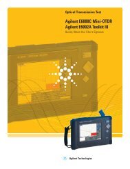
Version 06.02, February 2009Spectrum analyzer modeFrequencyFrequency rangeFrequency resolutionR&S ® FSUP8 DC-coupled 20 Hz to 8 GHzAC-coupled1 MHz to 8 GHzR&S ® FSUP26 DC-coupled 20 Hz to 26.5 GHzAC-coupled10 MHz to 26.5 GHzR&S ® FSUP50 DC-coupled 20 Hz to 50 GHz0.01 HzFrequency displayMarker resolutionUncertaintywith marker or frequency counter1 Hz±(marker frequency × referenceuncertainty + 10 % × resolution bandwidth+ ½ (span/(sweep points – 1)) + 1 Hz)span/624Marker tuning frequency step size defaultmarker step size = sweep points span/(sweep points – 1)Frequency counter resolution selectable 0.1 Hz to 10 kHzCount accuracy S/N > 25 dB ±(frequency × reference error + ½ (last digit))Display range for frequency axis0 Hz, 10 Hz to max. frequencyResolution0.1 HzMax. span deviation 1 %Spectral purity, SSB phase noise (1 Hz) f = 640 MHz, +20 °C to +30 °CResidual FM RBW 10 kHz, RMS
Version 06.02, February 20090R&S ® FSUP center frequency 200 MHz–20R&S ® FSUP center frequency 1 GHzSingle sideband phase noise in dBc (1 Hz)–40–60–80–100–120–140R&S ® FSUP center frequency 5 GHzR&S ® FSUP center frequency 25 GHzR&S ® FSUP center frequency 40 GHzR&S ® FSUP center frequency 50 GHz–160–18010 Hz 100 Hz 1 kHz 10 kHz 100 kHz 1 MHz 10 MHzSweepSweep timetime sweep, span = 0 Hz1 μs to 16000 s in 5 % stepsfrequency sweep, span ≥ 10 Hz 2.5 ms to 16000 s in steps of ≤10 %Max. deviation of sweep time 3 %Measurement in time domainwith marker and cursor lines(resolution 31.25 ns)Resolution bandwidthsSweep filters3 dB bandwidths 10 Hz to 20 MHz in 1/2/3/5 sequence,50 MHzBandwidth uncertainty10 Hz to 100 kHz (digital)
Version 06.02, February 2009EMI filters6 dB bandwidths 200 Hz, 9 kHz, 120 kHzBandwidth uncertainty3 %, nominalShape factor 60 dB : 3 dB
Version 06.02, February 2009LevelDisplay rangeMaximum input leveldisplayed noise floor to +30 dBmDC voltageRF input, AC-coupled50 VRF input, DC-coupled0 VCW RF powerRF attenuation 0 dB 20 dBm (= 0.1 W)RF attenuation ≥ 10 dB 30 dBm (= 1 W)Pulse spectral density97 dBµV/MHzMax. pulse voltage RF attenuation ≥ 10 dB 150 VMax. pulse energy RF attenuation ≥ 10 dB, 10 µs 1 mWsIntermodulation1 dB compression of input mixerThird-order intercept point (TOI)Second harmonic intercept (SHI)0 dB RF attenuation≤3.6 GHz +13 dBm, nominal>3.6 GHzR&S ® FSUP8+10 dBm, nominalR&S ® FSUP26, R&S ® FSUP50+7 dBm, nominal0 dB RF attenuation; level 2 × –10 dBm, ∆f > 5 × RBW or 10 kHz, whichever is largerR&S ® FSUP810 MHz ≤ f in < 300 MHz >17 dBm, typ. 20 dBm300 MHz ≤ f in ≤ 3.6 GHz >20 dBm, typ. 25 dBm3.6 GHz ≤ f in ≤ 8 GHz >18 dBm, typ. 23 dBmR&S ® FSUP2610 MHz ≤ f in < 300 MHz >17 dBm, typ. 20 dBm300 MHz ≤ f in < 3.6 GHz >22 dBm, typ. 27 dBm3.6 GHz ≤ f in < 26.5 GHz >12 dBm, typ. 15 dBmR&S ® FSUP5010 MHz ≤ f in < 300 MHz >17 dBm, typ. 20 dBm300 MHz ≤ f in < 3.6 GHz >22 dBm, typ. 27 dBm3.6 GHz ≤ f in < 26.5 GHz >12 dBm, typ. 15 dBm26.5 GHz ≤ f in < 28 GHz >8 dBm, typ. 11 dBm28 GHz ≤ f in < 40 GHz >12 dBm, typ. 15 dBmf in > 40 GHz12 dBm, nominal0 dB RF attenuationf in < 100 MHz>35 dBm100 MHz < f in ≤ 400 MHz >45 dBm, typ. 55 dBm400 MHz < f in ≤ 500 MHz >52 dBm, typ. 60 dBm500 MHz < f in ≤ 1 GHz >45 dBm, typ. 55 dBm1 GHz < f in ≤ 1.8 GHz >35 dBmR&S ® FSUP8, R&S ® FSUP26, R&S ® FSUP50f in > 1.8 GHz>80 dBm, nominalRohde & Schwarz R&S ® FSUP Signal Source Analyzer 15
Version 06.02, February 2009Displayed average noise level0 dB RF attenuation, termination 50 Ω, logarithmic scaling, normalized to 1 Hz RBWf < 10 kHz: 10 Hz FFT filter, trace average, sweep count = 20f ≥ 10 kHz: RBW = 1 kHz, VBW = 3 kHz, zero span, sweep time 50 ms, sampledetector, trace average, sweep count = 20, mean marker20 Hz
Version 06.02, February 2009Immunity to interferenceImage frequencyIntermediate frequencySpurious responseOther interfering signalsf ≤ 3.6 GHz>90 dB suppression, typ. >110 dB3.6 GHz < f ≤ 40 GHz >70 dB suppression, typ. >100 dBf > 40 GHz70 dB suppression, nominalf = receive frequencyf ≤ 3.6 GHz>90 dB suppression, typ. >110 dB3.6 GHz < f ≤ 4.2 GHz typ. 70 dB suppression4.2 GHz < f ≤ 50 GHz >70 dB suppression, typ. >90 dBf = receive frequencyf > 1 MHz, without input signal, 100 kHzmixer level < –10 dBm, f in ≤ 2.3 GHz
Version 06.02, February 2009Level measurement uncertaintyAbsolute level uncertainty at 128 MHzFrequency responsereferenced to 128 MHzAttenuator switching uncertaintyUncertainty of reference level settingRBW = 10 kHz, level –30 dBm,
Version 06.02, February 2009I/Q <strong>data</strong>GeneralInterfaceSampling rateADC resolutionI/Q memoryMax. equalized bandwidthIF prefilter bandwidthGPIB or LAN interfaceprogrammable: 10 kHz to 81.6 MHz in0.1 Hz steps14 bit16 Msample each for I and Q <strong>data</strong>7 MHz300 kHz to 10 MHz, 1/2/3/5 stepsTrigger functionsTriggerTrigger sourceTrigger offsetMax. deviation of trigger offsetGated sweepGate sourceGate delayGate lengthMax. deviation of gate lengthspan ≥ 10 Hzspan = 0 Hzfree run, video, external, IF level(mixer level 10 dBm to –50 dBm)125 ns to 100 s, resolution min. 125 ns(or 1 % of offset)±(125 ns to 100 s), resolution min. 125 ns,depending on sweep time±(31.25 ns + (0.1 % × trigger offset))external, IF level, video1 µs to 100 s125 ns to 100 s, resolution min. 125 ns or1 % of gate length±(31.25 ns + (0.05 % × gate length))Inputs and outputs (front panel)RF inputImpedanceConnectorVSWRSetting range of attenuator50 ΩR&S ® FSUP8N femaleR&S ® FSUP26test port adapter, APC 3.5 mm/N femaleR&S ® FSUP50test port adapter, 2.4 mm/N femaleRF attenuation ≥ 10 dB, DC-coupledf < 3.6 GHz
Version 06.02, February 2009Probe power supplySupply voltages+15 V DC, –12.6 V DC and ground,max. 150 mA, nominalPower supply for antennas, etc.Supply voltages5-pin connector±10 V and ground, max. 100 mA, nominalDC ports 1 and 2BNC connectorSupply voltages 0 V to 12 V, max. 500 mA, nominal 9Tuning ports 1 and 2BNC connectorSupply voltages –10 V to 28 V, max. 20 mA, nominal 10AUX portSupply voltagesBNC connector–10 V to 0 V, max. 500 mA, nominalUSB interfaceupper connector type A plug, version 2.0lower connector type A plug, version 2.0Power supply for noise sourceOutput voltageBNC female0 V and 28 V, switchable, nominalInputs and outputs (rear panel)IF 20.4 MHzImpedanceBandwidthLevelBNC female50 ΩRBW ≤ 30 kHz1.67 × resolution bandwidth, min. 2.6 kHzRBW = 50 kHz, 100 kHz400 kHz200 kHz ≤ RBW ≤ 10 MHz equal to resolution bandwidthRBW ≤ 100 kHz, FFT filter,–20 dBm at reference levelmixer level > –70 dBmRBW = 200 kHz to 10 MHz,0 dBm at reference levelmixer level > –50 dBmIF 404.4 MHz active only if RBW > 10 MHz BNC femaleImpedance50 ΩBandwidth RBW > 10 MHz equal to resolution bandwidthLevel mixer level ≤ 0 dBm typ. –10 dBVideo outputImpedanceOutput voltageRBW ≥ 200 kHz, logarithmic scaling,full scaleBNC female50 Ω0 V to 1 V (EMF)Reference outputImpedanceOutput frequencyLevelBNC female50 Ω10 MHz>0 dBm, nominalReference inputBNC femaleImpedance50 ΩInput frequency range 1 MHz ≤ f in ≤ 20 MHz, in 1 Hz steps 2Required level>0 dBm into 50 ΩSweep outputOutput voltageBNC female0 V to 5 V, proportional to displayedfrequency20 Rohde & Schwarz R&S ® FSUP Signal Source Analyzer
Version 06.02, February 2009External trigger/gate inputTrigger voltageInput impedanceBNC female1.4 V (TTL)≥10 kΩIEC/IEEE bus control interface in line with IEC 625-2(IEEE 488.2)Command setSCPI 1997.0 or HP85XX compatibleConnector24-pin Amphenol femaleInterface functionsSH1, AH1, T6, L4, SR1, RL1, PP1, DC1,DT1, C0LAN interface10/100BaseT, RJ-45USB interfaceupper connector type A plug, version 1.1lower connector type A plug, version 2.0Serial interfaceRS-232-C (COM), 9-pin female connectorsPrinter interfaceparallel (Centronics compatible)Mouse interfacePS/2 compatibleConnector for external monitor (VGA)15-pin D-SubRohde & Schwarz R&S ® FSUP Signal Source Analyzer 21
Version 06.02, February 2009General <strong>data</strong>Display 21 cm LC TFT color display (8.4")Resolution800 × 600 pixel (SVGA resolution)Pixel failure rate 500 instrument settings and tracesEnvironmental conditionsTemperatureClimatic loadingoperating temperature range +5 °C to +40 °Cpermissible temperature range 0 °C to +50 °C+40 °C at 85 % relative humidity(EN 600-2-30: 2000-02)Mechanical resistanceVibrationShockRecommended calibration intervalRFI suppressionsinusoidalrandomR&S ® FSU-B20 option: random vibrationoperation with external referenceoperation with internal reference5 Hz to 150 Hz, max. 2 g at 55 Hz;0.5 g from 55 Hz to 150 Hz;in line with EN 60068-2-6,EN 61010-1, MIL-T-28800D, class 510 Hz to 100 Hz, acceleration 1 g (rms)40 g shock spectrum, in line withMIL-STD-810D Method Nr.516.4, DIN EN60068-2-2710 Hz to 300 Hz, acceleration 1.9 g (rms)2 years1 yearin line with new EMC Directive2004/108/EC, including:IEC/EN 61326 class B (emission)CISPR 11/EN 55011 group 1 class B(emission)IEC/EN 61326 table A.1 (immunity,industrial)Power supplyAC supply 100 V to 240 V, 3.1 A to 1.3 A,50 Hz to 400 Hz,class of protection I in line with VDE 411Power consumptionR&S ® FSUP8typ. 130 VAR&S ® FSUP26, R&S ® FSUP50typ. 150 VASafety in line with EN 61010-1, UL 3111-1,CSA C22.2 No. 1010-1, EN 61010-1Test markVDE, GS, CSA, CSA-NRTLDimensions W × H × D 435 mm × 192 mm × 460 mm(17.13 in × 7.56 in × 18.11 in)Weight (without options) 12 13R&S ® FSUP817.6 kg (38.8 lb)R&S ® FSUP2618.1 kg (39.9 lb)R&S ® FSUP5018.6 kg (41 lb)12 If the instrument is equipped with the R&S ® FSUP-B60 option, 1.2 kg have to be added.13 If the instrument is equipped with the R&S ® FSUP-B61 option, 1.5 kg have to be added.22 Rohde & Schwarz R&S ® FSUP Signal Source Analyzer
Version 06.02, February 2009R&S ® FSUP-B21 LO/IF ports for external mixers(for R&S ® FSUP26 and R&S ® FSUP50 only)LO signalFrequency rangeLevel +20 °C to +30 °C+5 °C to +40 °C7 GHz to 15.5 GHz+15.5 dBm ±1 dB+15.5 dBm ±3 dBIF inputIF frequencyFull scale levelLevel uncertainty404.4 MHz2-port mixer–20 dBm(LO output/IF input, front panel)3-port mixer (IF input, front panel) –20 dBmIF input level –30 dBm, RBW 30 kHz, 2-port mixer, LO output/IF input(front panel)+20 °C to +30 °C
Version 06.02, February 2009R&S ® FSU-B25 electronic attenuatorFrequencyFrequency rangeR&S ® FSUP8R&S ® FSUP26, R&S ® FSUP50100 kHz to 8 GHz100 kHz to 3.6 GHzSetting range<strong>Electro</strong>nic attenuatorPreamplifier0 dB to 30 dB, in 5 dB steps20 dB, switchableLevel measurement uncertaintyFrequency responseReference errorwith preamplifier or electronic attenuator10 MHz to 50 MHz
Version 06.02, February 2009R&S ® FSUP-Z1 AM noise detectorMeasurement rangeConnectorsInput impedanceFrequency rangeInput levelEffective system <strong>data</strong>inputAPC 3.5 mm (male)output SMC 1450 Ω, nominal10 MHz to 26.5 GHz, typ.10 MHz to 17 GHz –10 dBm to +15 dBm17 GHz to 20 GHz –10 dBm to +12 dBm20 GHz to 26.5 GHz –10 dBm to +10 dBmThe specified effective system <strong>data</strong> are achieved after performing the appropriate system error calibration.The <strong>data</strong> are valid between +20 °C and +30 °C, with a power of ≥ +10 dBm at the detector input and a termination resistance of 400 Ω atthe detector output.Input frequency rangeAM noise frequency offset range (3 dB)Input VSWRGeneral <strong>data</strong>The specified <strong>data</strong> are valid for the AM noise detector without the adapter cable.Temperature loadingMaximum rated input powerCalibration intervalDimensions (length × diameter)WeightShipping weightinput frequencyAM noise conversion gain10 MHz >–8 dB, typ.30 MHz >–7 dB, typ.100 MHz >–5 dB, typ.1 GHz >–5 dB, typ.10 GHz >–5 dB, typ.20 GHz >–6 dB, typ.26 GHz >–7 dB, typ.1 Hz to 3 MHz, nominal10 MHz to 18.5 GHz 1.5:1, nominal18.5 GHz to 26.5 GHz 2:1, nominaloperating temperature range +20 °C to +30 °Cpermissible temperature range 5 °C to +40 °Cstorage temperature range –40 °C to +70 °Cin line with IEC 60068-2-1 andIEC 60068-2-2200 mW2 years43 mm × 10 mm1.7 in × 0.38 in17 g (0.04 lb)1 kg (2.2 lb)14 An adapter cable SMC to BNC is supplied with the AM noise detector.Rohde & Schwarz R&S ® FSUP Signal Source Analyzer 25
Version 06.02, February 2009Ordering informationDesignation Type Order No.Signal Source Analyzer, 20 Hz to 8 GHz R&S ® FSUP8 1166.3505.09Signal Source Analyzer, 20 Hz to 26.5 GHz R&S ® FSUP26 1166.3505.27Signal Source Analyzer, 20 Hz to 50 GHz R&S ® FSUP50 1166.3505.51Accessories suppliedPower cable, printed quick start guide and CD-ROM (with operating manual and service manual)R&S ® FSUP26: test port adapter with 3.5 mm female (1021.0512.00) and N female (1021.0535.00) connectorR&S ® FSUP50: test port adapter with 2.4 mm female (1088.1627.02) and N female (1036.4777.00) connectorOptionsDesignation Type Order No. Retrofit RemarksOptionsLow-Aging OCXO R&S ® FSU-B4 1144.9000.02 yesExternal Generator Control R&S ® FSP-B10 1129.7246.03 yesRemovable Hard Disk R&S ® FSUP-B18 1303.0400.05 noSecond Hard Disk for R&S ® FSP-B18 R&S ® FSUP-B19 1303.0600.05 yes requires R&S ® FSUP-B18LO/IF Ports for External Mixers R&S ® FSUP-B21 1157.1090.04 yes for R&S ® FSUP26 only20 dB Preamplifier, 3.6 GHz to 26.5 GHz R&S ® FSU-B23 1157.0907.02 no for R&S ® FSUP26 only,requires R&S ® FSU-B25<strong>Electro</strong>nic Attenuator, 0 dB to 30 dB,R&S ® FSU-B25 1144.9298.02 yesand 20 dB Preamplifier (3.6 GHz)Trigger Port R&S ® FSP-B28 1162.9915.02 yesLow Phase Noise R&S ® FSUP-B60 1169.5544.03 yesCorrelation Extension R&S ® FSUP-B61 1305.2500.26 no for R&S ® FSUP26 only,requires R&S ® FSUP-B60Correlation Extension (with 26.5 GHz preamplifier) R&S ® FSUP-B61 1305.2500.23 no for R&S ® FSUP26 only,requires R&S ® FSUP-B60,R&S ® FSU-B25,R&S ® FSU-B23Correlation Extension R&S ® FSUP-B61 1305.2500.50 no for R&S ® FSUP50 only,requires R&S ® FSUP-B60Firmware/softwareGSM/EDGE Application Firmware R&S ® FS-K5 1141.1496.02Bluetooth ® Application Firmware R&S ® FS-K8 1157.2568.02Power Sensor Measurements R&S ® FS-K9 1157.3006.02Application Firmware for Noise Figure and GainMeasurementsR&S ® FS-K30 1300.6508.02 preamplifier recommended(e.g. R&S ® FSU-B25)Vector Signal Analysis R&S ® FSQ-K70 1161.8038.023GPP BTS/Node B FDD Application Firmware R&S ® FS-K72 1154.7000.023GPP UE FDD Application Firmware (including R&S ® FS-K73 1154.7252.02HSUPA)3GPP HSDPA BTS Application Firmware R&S ® FS-K74 1300.7156.02 requires R&S ® FS-K723GPP TD-SCDMA BTS Application Firmware R&S ® FS-K76 1300.7291.023GPP TD-SCDMA UE Application Firmware R&S ® FS-K77 1300.8100.02CDMA2000 ® IS-95 (cdmaOne)/1xEV-DV BTS R&S ® FS-K82 1157.2316.02Application FirmwareCDMA2000 ® 1xEV-DV MS Application Firmware R&S ® FS-K83 1157.2416.02CDMA2000 ® 1xEV-DO BTS Application Firmware R&S ® FS-K84 1157.2851.02(including Rev A)CDMA2000 ® 1xEV-DO MS Application Firmware R&S ® FS-K85 1300.6689.02The Bluetooth word mark and logos are owned by the Bluetooth SIG, Inc. and any use of such marks by Rohde & Schwarz is under license.CDMA2000 ® is a registered trademark of the Telecommunications Industry Association (TIA - USA).26 Rohde & Schwarz R&S ® FSUP Signal Source Analyzer
Version 06.02, February 2009Recommended extrasDesignation Type Order No.IEC/IEEE Bus Cable, 1 m R&S ® PCK 0292.2013.10IEC/IEEE Bus Cable, 2 m R&S ® PCK 0292.2013.2019” Rack Adapter R&S ® ZZA-411 1096.3283.00Adapter for mounting on telescopic rails R&S ® ZZA-T45 1109.3774.00(only with R&S ® ZZA-411 adapter)Matching pads, 50/75 ΩL Section, matching at both ends R&S ® RAM 0358.5414.02Series Resistor, 25 Ω, matching at one R&S ® RAZ 0358.5714.02end (taken into account in instrumentfunction RF INPUT 75 Ω)SWR bridges, 50 ΩSWR Bridge, 5 MHz to 3 GHz R&S ® ZRB2 0373.9017.5X (X = 2/3/5/6)SWR Bridge, 40 kHz to 4 GHz R&S ® ZRC 1039.9492.5X (X = 2/5)High-power attenuators100 W, 3/6/10/20/30 dB, 1 GHz R&S ® RBU100 1073.8495.XX (XX = 03/06/10/20/30)50 W, 3/6/10/20/30 dB, 2 GHz R&S ® RBU50 1073.8695.XX (XX = 03/06/10/20/30)50 W, 20 dB, 6 GHz R&S ® RDL50 1035.1700.52Connectors and cablesProbe power connector, 3-pin 1065.9480.02DC blocksDC Block, 10 kHz to 18 GHz (type N) R&S ® FSE-Z4 1084.7443.02External harmonic mixers (for R&S ® FSUP26, R&S ® FSUP50 with R&S ® FSUP-B21 option)Harmonic Mixer, 40 GHz to 60 GHz R&S ® FS-Z60 1089.0799.02Harmonic Mixer, 50 GHz to 75 GHz R&S ® FS-Z75 1089.0847.02Harmonic Mixer, 60 GHz to 90 GHz R&S ® FS-Z90 1089.0899.02Harmonic Mixer, 90 GHz to 110 GHz R&S ® FS-Z110 1089.0947.04AM noise detectorAM noise detector R&S ® FSUP-Z1 1305.2700.02For R&S ® FSUP26 onlyTest port adapter, N male 1021.0541.00Test port adapter, 3.5 mm male 1021.0529.00Microwave Measurement Cable with R&S ® FSE-Z15 1046.2002.02N male and 3.5 mm male test port adaptersetFor R&S ® FSUP50 onlyTest port adapter, N male 1036.4783.00Test port adapter, K male 1036.4802.00Test port adapter, K female 1036.4802.00Rohde & Schwarz R&S ® FSUP Signal Source Analyzer 27
Service you can rely onJ In 70 countriesJ Person-to-personJ Customized and flexibleJ Quality with a warrantyJ No hidden termsAbout Rohde & SchwarzRohde & Schwarz is an independent group of companiesspecializing in electronics. It is a leading supplier of solutionsin the fields of test and measurement, broadcasting,radiomonitoring and radiolocation, as well as secure communications.Established 75 years ago, Rohde & Schwarzhas a global presence and a dedicated service network inover 70 countries. Company headquarters are in Munich,Germany.Regional contactEurope, Africa, Middle East+49 1805 12 42 42* or +49 89 4129 137 74customersupport@rohde-schwarz.comNorth America1 888 TEST RSA (1 888 837 87 72)customer.support@rsa.rohde-schwarz.comLatin America+1 410 910 79 88customersupport.la@rohde-schwarz.comAsia/Pacific+65 65 13 04 88customersupport.asia@rohde-schwarz.comCertified Quality SystemISO 9001DQS REG. NO 1954 QMCertified Environmental SystemISO 14001DQS REG. NO 1954 UMFor product brochure,see PD 5213.6729.12and www.rohde-schwarz.comRohde & Schwarz GmbH & Co. KGMühldorfstraße 15 | 81671 MünchenPhone +49 89 41 290 | Fax +49 89 41 29 121 64www.rohde-schwarz.comR&S® is a registered trademark of Rohde & Schwarz GmbH & Co. KGTrade names are trademarks of the owners | Printed in Germany (as/sv)PD 5213.6729.22 | Version 06.02 | February 2009 | R&S®FSUPSubject to change*0.14 €/min within German wireline network; rates may vary in othernetworks (wireline and mobile) and countries.