PDF Hydro Leduc XP serie - Total Hydraulics BV
PDF Hydro Leduc XP serie - Total Hydraulics BV
PDF Hydro Leduc XP serie - Total Hydraulics BV

Create successful ePaper yourself
Turn your PDF publications into a flip-book with our unique Google optimized e-Paper software.
hydraulic piston pumps for trucks<strong>XP</strong>Series
Contents■■Design of <strong>XP</strong> <strong>serie</strong>s pumps...................... 1■■Range and characteristics ....................... 2■■Performance. ................................. 3■■Dimensions .................................. 4■■Changing direction of rotation..................... 5■■Accessories. ................................. 6■■Shaft sealing ................................. 7■■Installation and start-up recommendations........... 8■■The complete LEDUC product range............... 9A complete range dedicated to truck hydraulicsPA-PAC-XSeriesA range of axial piston pumps: single flow models from 12 to144 cc/rev, twin flow models from 2 x 25 to 2 x 75 cc/rev.Literature on request or on our website : www.hydroleduc.comXASeriesThe SAE version of <strong>XP</strong> bent axis pumps.Literature on request or on our website : www.hydroleduc.comTXVSeriesVariable displacement pumps with flowand pressure regulation (Load Sensing).Literature on request or on our website : www.hydroleduc.comHYDRO LEDUCHead Office & FactoryBP 9F-54122 AZERAILLES (FRANCE)Tél. +33 (0)3 83 76 77 40Fax +33 (0)3 83 75 21 58
Design of<strong>XP</strong> <strong>serie</strong>s pumpsThe <strong>XP</strong> range pumps are designed for the most severe working conditionsin terms of :--space available ;--drive speed of the pump ;--power required.To meet such performance criteria, <strong>Hydro</strong> <strong>Leduc</strong> opted for the “bent axis”concept, and optimized the pump design in several ways :--7 pistons ;--original idea for plate – barrel synchronisation ;--change of direction of rotation by simply changing a fitting ;--use of materials with high mechanical resistance ;--reinforced sealing.The <strong>XP</strong> pumps therefore offer exceptional performance :--greatly reduced noise levels ;--high rotating speeds ;--simple to use ;--long service life.The exceptional compacityof the <strong>XP</strong> pumps, together withtheir technology, means they canbe installed in the most challengingsize envelopes and where rotatingspeed – due to the PTO ratio forexample – is high.1
Range and characteristics<strong>XP</strong> <strong>serie</strong>s pumps■■10 models- from 12 to 130 cc- 350 bar continuous working pressure- 400 bar peak pressure- maximum speed from 1750 to 3150 rpmMinimum size envelopeHigh rotating speedsHigh output pressure2Pump referenceDisplac.MaximumcontinuouspressureMaximumintermittent peakpressure 5 secondsMaximum rotatingspeed at absolutepressure 1 barwith pipe 2"Maximumtorque absorbedat 350 barwithout inletfittingWeightwith inletfittingOverhang torquewithoutinlet fittingwith inletfittingcc bar bar rpm Nm kg kg N.m N.m<strong>XP</strong>12 0518510 12 350 400 3150 71 9.2 9.65 8.74 9.17<strong>XP</strong>18 0517655 18 350 400 2900 107 9.25 9.7 8.79 9.21<strong>XP</strong>25 0517665 25 350 400 2650 148 9.3 9.75 8.84 9.26<strong>XP</strong>32 0517640 32 350 400 2700 190 11.1 11.55 11.1 11.55<strong>XP</strong>41 0517650 41 350 400 2500 243 11.15 11.6 11.15 11.6<strong>XP</strong>50 0517625 50.3 350 400 2500 292 11.2 11.65 11.76 12.23<strong>XP</strong>63 0517635 63 350 400 2300 362 11.25 11.7 11.81 12.28<strong>XP</strong>80 0517610 80.4 350 400 2150 460 14.84 15.3 17.82 18.36<strong>XP</strong>108 0517620 108.3 350 400 1950 619 14.95 15.4 17.94 18.48<strong>XP</strong>130 0517795 129.8 350 400 1750 730 15.35 15.8 18.73 19.28
Performance<strong>XP</strong> <strong>serie</strong>s pumps■■Torque absorbed as a function of pump output pressureTorque (m.daN)8070<strong>XP</strong> 130<strong>XP</strong> 1086050<strong>XP</strong> 8040<strong>XP</strong> 6330<strong>XP</strong> 50<strong>XP</strong> 412010<strong>XP</strong> 32<strong>XP</strong> 25<strong>XP</strong> 18<strong>XP</strong> 120040 60 80 100 120 140 160 180 200 220 240 260 280 300 320 340 360Pressure(bar)■■FlowQ (l/mim)<strong>XP</strong> 1303200<strong>XP</strong> 108<strong>XP</strong> 80150<strong>XP</strong> 63<strong>XP</strong> 50100<strong>XP</strong> 41<strong>XP</strong> 32<strong>XP</strong> 2550<strong>XP</strong> 18<strong>XP</strong> 1200 5001000 1500 20002500 3000N (rpm)■■Volumetric efficiency%100Efficiency at 1,000 rpmThese graphs are the results of testworkdone in the HL R&D laboratory,on a specific test bench, with an ISO46 fluid at 77°F/25°C (100 cSt), thepump is fitted with an 2" HL inlet fitting,hosing is 13 feet (4 metres) long,and tank situated slightly above pump.900100200300 350 (bar)Pressure
Dimensions<strong>XP</strong> <strong>serie</strong>s pumps+ 0.255 − 0.47 14.5EAB40F801.9± 0.125.95± 0.14 x M12 80 − 0.013040°4080D+ 0.237.9 − 0.4C4 x 12.75Splined shaft: 8-32-36DIN ISO 14-NF 22.131G3/8"GHGAdditional bore on the shaftavailable on request.18.2 ± 0.05± 0.05 8.15Shaft borded throughGview G4Pump reference A B C D E F G H<strong>XP</strong>12 0518510 196.7 177.8 77.1 103.9 85.7 108 3/4" 54<strong>XP</strong>18 0517655 196.7 177.8 77.1 103.9 85.7 108 3/4" 54<strong>XP</strong>25 0517665 196.7 177.8 77.1 103.9 85.7 108 3/4" 54<strong>XP</strong>32 0517640 202.8 184 82.3 109.1 85.7 108 3/4" 54<strong>XP</strong>41 0517650 202.8 184 82.3 109.1 85.7 108 3/4" 54<strong>XP</strong>50 0517625 214.4 195.6 92 118.9 85.7 108 3/4" 54<strong>XP</strong>63 0517635 214.4 195.6 92 118.9 85.7 108 3/4" 54<strong>XP</strong>80 0517610 241.7 220.9 103.5 133.3 97.4 123 1" 60<strong>XP</strong>108 0517620 241.7 222.5 104.8 133.3 97.4 123 1" 60<strong>XP</strong>130 0517795 244 224.8 106.7 135.2 97.4 123 1" 60■■Inlet fittings for <strong>XP</strong> pumpsAll <strong>XP</strong> pumps are supplied with their inlet fitting. Please specify required fitting from the choice below when ordering.45° elbow fittingsReference x hose x A E F0517894 1 ½" 39.1 91.7 46.7 A0517896 42 43 91.7 46.70517897 1 ¾" 46 91.7 46.70517893 2" 51.8 108.4 54.40517892 2 ½" 64.5 125.2 62.290° elbow fittingsReference x hose x A E F0517947 1 ½" 39.1 58.6 79.5EFEF A0517946 2" 51.8 64.9 80.20517945 2 ½" 64.5 71.3 87.5
Direction of Dimensions rotation<strong>XP</strong> <strong>serie</strong>s pumps■■How to change the direction of rotation of the pumpAll LEDUC <strong>XP</strong> pumps are supplied for Clockwise rotation (CW) unless otherwisespecified on each purchase order.To check in which direction the pump should rotate on your installation:--check the direction of rotation of the PTO;--if the PTO turns clockwise, the pump must rotate counter-clockwise, andvice versa.To change the direction of rotation of your <strong>XP</strong> pump:--remove the inlet fitting (2) and the 2 parts of the split flange (3).--remove the rotation setting screw (1).--remove the plug (6).--put the rotation setting screw (1) where the plug (6) was, and the plug (6)where the rotation setting screw (1) was.--put seal (5) on the inlet fitting, then the inlet fitting on the side where theplug (6) is, and fix with the split flange. Tighten with the screws (4).Important note:Do not rotate pump shaft at all until the rotation setting screw (1) is in place.The rotation setting screw is always on the output (pressure) side.The various parts should be tightened to the following torque valves :Tightening torque of rotation setting screw (1) in m.daN 4Tightening torque of fixation screws (4) in m.daN 2.5Tightening torque of plug (6) in m.daN 2.55■■Pump CCW■■Pump CW661616ASPIRATION / INLETREFOULEMENT / OUTLETA Création du planInd.Protection/traitement : -Chaîne de côtes :Masse- KgFormatA1Echelle1:5Folio1/1PLAN ETUDETolérances géométriques : Norme ISO 2768-HTolérances angulaires : Norme ISO 2768-cTolérances dimensionnelles : Norme ISO 2768-mRa 3.2Etat de surface sauf indication :--WMVér. parRe mini : - N/mm²Rm mini : - N/mm²A% : -%--/--/-- --/--/-- ----N° BTP
Accessories<strong>XP</strong> <strong>serie</strong>s pumps■■By-pass valve for <strong>XP</strong> pumpsFor <strong>XP</strong> pump applications where the pump is driven by a continuous runningPTO (PTO which cannot be disengaged), <strong>Hydro</strong> <strong>Leduc</strong> offers a by-passvalve which is fitted onto the back of the pump. This solution allows thecontinuous running of the pump :--without creating problems of fluid overheating ;--without affecting pump service life ;--with no modifications necessary to the hydraulic equipment on the truck.■■How does it work ?The by-pass valve is a 12 or 24 Volt solenoid valve. When not activated, itenables pump output to link up to pump inlet. When it is activated, the pumpoper ates normally (output flow).<strong>Leduc</strong> part number 12 Volt 24 Volt<strong>XP</strong>12 to <strong>XP</strong>63 BP63 0521180 BP63 0517931<strong>XP</strong>80 to <strong>XP</strong>130 BP80 0521185 BP80 0517811■■Overhang torque of <strong>XP</strong> pumps fitted with by-pass valvesPumpmodelwithout inletfittingWeightwith inletfitting 2"without inletfittingOverhang torquewith inletfitting2"kg kg N.m N.m<strong>XP</strong>12 12.8 13.25 16.32 16.90<strong>XP</strong>18 12.85 13.3 16.39 16.96<strong>XP</strong>25 12.9 13.35 16.44 17.02<strong>XP</strong>32 14.7 15.15 18.98 19.56<strong>XP</strong>41 14.75 15.2 19.04 19.62<strong>XP</strong>50 14.8 15.25 20.05 20.676MApplicationcircuit<strong>XP</strong>63 14.85 15.3 20.12 20.73<strong>XP</strong>80 18.45 18.9 27.16 27.82<strong>XP</strong>108 18.55 19 27.31 27.97<strong>XP</strong>130 18.95 19.4 28.16 28.93For some applications, we recommend using an external drain.BCAdrain G ¼"FEDGH118J■■Dimensions including by-pass valvePump model A B C D E F G H J<strong>XP</strong> 12 / 18 / 25 289.35223.04202.19132.20114.72 97.58 3/4" 54 108<strong>XP</strong> 32 / 41 295.5 229 208.3 137.3 120.1 102.7 3/4" 54 108<strong>XP</strong> 50 / 63 307.1 240.4 220 147.1 129.7 112.5 3/4" 54 108<strong>XP</strong> 80 / 108 334 269 246.7 157.8 143.9 124.8 1" 60 123<strong>XP</strong> 130 336.3 271.3 249 159.7 145.8 126.7 1" 60 123.5
Shaft sealing<strong>XP</strong> <strong>serie</strong>s pumps<strong>Leduc</strong> pumps destined for truck hydraulics (<strong>XP</strong>, PA, PAC and TXV<strong>serie</strong>s) are all fitted with reinforced sealing comprising :■■Examples of tube attachment●●two radial seals : an external seal adapted to the needs of PTOs and gearboxes;and an internal seal adapted to the needs of hydraulic performance;●●an original protection of the pump shaft seals. This is a flexible transparenttube which avoids any entry of contaminants between the two seals, andguarantees high pressure water jet cleaning of vehicle will not damage thesealing area. It also allows air vent of the chamber between the two seals.✔ Recommendations for attaching the protective tube :●●make a siphon with the tube so as to avoid any introduction of :●●dirt from road;●●water or damp from high pressure washing of vehicle;●●put the end of the tube downwards, or in a place sheltered from anyprojections;●●fix the tube in place using a collar/clip.7✘ Avoid :●●attaching the tube to any parts which may move, this could lead to it beingdamaged or torn off;●●any pinching or folds in the tube when fixing it in place;●●any obturation of the end of the tube.HYDRO LEDUC stresses that on non-sealed PTO installationsit is the hydraulic pump which ensures the sealing of thevehicle gearbox.This is why <strong>Hydro</strong> <strong>Leduc</strong> offers tried and tested solutions approvedby vehicle manufacturers.Note in particular the pump – PTO sealing via a frontal square sectionring seal ensuring metal to metal contact between pump and PTO.Do not use paper gasket.
Installation and start-up<strong>XP</strong> <strong>serie</strong>s pumpsMake sure your pumplives a long happy life !8■■The tank :Generally, hydraulic pumps much prefer a tank above the pump.<strong>Leduc</strong> pumps can also operate with oil level beneath the pump, for furtherinformation on such installations, please contact our Technical Department.Correct inlet conditions are between 0.8 to 2 bar absolute pressure.The tank should preferably have a separation between inlet side and return.This avoids fluid emulsion and the introduction of air into the hydraulic circuit.Ensure also that the suction is not from the very bottom of the tank, so as toprotect the pump from any deposits (particles).■■Hosing :Should be dimensioned to ensure flow between 0.5 and 0.8 m/second.Choose as direct a supply line as possible, avoiding sharp bends.■■Filtration :<strong>Hydro</strong> <strong>Leduc</strong> recommends using a very clean tank, filtered during filling andwith filter on air vent.The pump supply line must be cleaned (decontaminated) and the return lineshould be filtered as follows :--for relatively simple circuits (e.g. tippers) :use a 20 micron filter on pump return line.--for more complex circuits (e.g. cranes) :Ideal solution :--high pressure filter between the pump and the crane hydraulic circuit ;--10 to 20 micron filter ;--clogging indicato.■■Preparation of the pump :For <strong>XP</strong> pumps, check the direction of rotation needed, and change it if necessary.See instructions on page 5.Before start-up, the pumps should be filled with oil. This is essential for <strong>XP</strong>pumps.■■Start-up :--open the supply valve if there is one ;--check the valve is in “back to tank” position ;--partially unscrew the output fitting ;--start up at low speed, or by successive starts/stops ;--retighten the output connector as soon as air bubbles have disappeared ;--let the pump run for one to two minutes, and check that the flow is wellestablished ;--check the pump is running correctly, with no vibrations nor abnormal noise;--after several hours of operation, check the tightening torque of the pumpfixture to PTO.■■Maintenance :Some regular checks are necessary, namely :--tightening of pump to PTO ;--cleanliness of fluid ;--state of filter ;if you notice traces of oil in the plastic tube, it is essential tocheck the sealing between PTO and pump.■■The fluid :Use a mineral hydraulic oil with viscosity between 10 and 400 cSt. It is in thisviscosity range that the pumps keep their volumetric characteristics. If youwish to use other fluids, please consult our Technical Department.Maximum temperature of fluid in the pump should not exceed 100°C.■■Drive and assemblyrecommendations :For PTO mount applications, be careful to respectthe tightening recommendations in terms of pumponto PTO and PTO onto vehicle gearbox.<strong>XP</strong> pumps are not designed to withstand any axialload on the pump shaft. Check your installationconforms to this requirement.
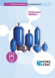
other product lineshydraulic motors<strong>XP</strong>Fixed displacementbent-axis pistons motors.Models from 12 to 126 cc.Available both in ISoand SAE versions.TXVPAPACPADpiston pumpsfor trucks<strong>Hydro</strong> LEduc offers 3 types of piston pumps perfectlysuited to all truck and PTo-mount applications.Fixed and variable displacement from 12 to 150 cc.micro-hydraulicsmobile andindustrial pumpsFixed displacement pumps, the W <strong>serie</strong>s, and variabledisplacement pumps, the dELTA <strong>serie</strong>s. High pressurecapabilities within minimal size.W <strong>serie</strong>s: fl anges to ISo 3019/2, shafts to dIN 5480.DELTA <strong>serie</strong>s: SAE shafts and fl anges.This is a fi eld of exceptional<strong>Hydro</strong> LEduc know-how:• axial and radial piston pumps,of fi xed and variable displacement,• axial piston micro-hydraulic motors,• micro-hydraulic units incorporatingpump, electric motors, valving, controls,etc.To users of hydraulic components which have tobe housed in extremely small spaces,<strong>Hydro</strong> LEduc offers complete, original and reliablesolutions for even the most diffi cult environments.we are passionateabout hydraulics…hydro-pneumaticaccumulatorsBladder, diaphragm accumulators.Spherical and cylindrical accumulators.Volume capacities from 20 cc to 50 liters.Pressures up to 500 bar.Accessories for use with hydraulic accumulators.A dedicated r&d team means <strong>Hydro</strong> LEduc is able to adapt or createproducts to meet specifi c customer requirements. Working in closecooperation with the decision-making teams of its customers, <strong>Hydro</strong> LEduc optimizesproposals based on the specifi cations submitted.
a passionfor hydraulicsHYDRO LEDUCHead Office & FactoryBP 9 - F-54122 AZERAILLES (FRANCE)Tél. +33 (0)3 83 76 77 40Fax +33 (0)3 83 75 21 58HYDRO LEDUC GmbHHaselwander Str. 5D-77746 SCHUTTERWALD (DEUTSCHLAND)Tel. +49 (0) 781-9482590Fax +49 (0) 781-9482592HYDRO LEDUC N.A., Inc.19416 Park Row - Suite 170HOUSTON, TEXAS 77084 (USA)Tel. +1 281 679 9654Fax +1 832 321 3553Complete catalogues available at:www.hydroleduc.comHYDRO LEDUCSAS with capital of 4 065 000 eurosSiret 319 027 421 00019RC Nancy B 319 027 421mail@hydroleduc.comThe information is given as rough guide. Not contractual document. Cancels and replaces previous version.Editech.com03/07/2012