APA Report T2005-08 - APA - The Engineered Wood Association
APA Report T2005-08 - APA - The Engineered Wood Association
APA Report T2005-08 - APA - The Engineered Wood Association

You also want an ePaper? Increase the reach of your titles
YUMPU automatically turns print PDFs into web optimized ePapers that Google loves.
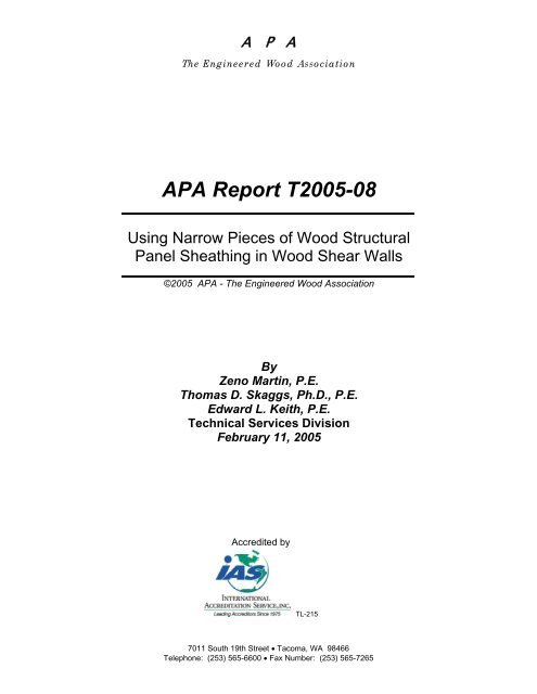
A P A<strong>The</strong> <strong>Engineered</strong> <strong>Wood</strong> <strong>Association</strong><strong>APA</strong> <strong>Report</strong> <strong>T2005</strong>-<strong>08</strong>Using Narrow Pieces of <strong>Wood</strong> StructuralPanel Sheathing in <strong>Wood</strong> Shear Walls©2005 <strong>APA</strong> - <strong>The</strong> <strong>Engineered</strong> <strong>Wood</strong> <strong>Association</strong>ByZeno Martin, P.E.Thomas D. Skaggs, Ph.D., P.E.Edward L. Keith, P.E.Technical Services DivisionFebruary 11, 2005Accredited byTL-2157011 South 19th Street • Tacoma, WA 98466Telephone: (253) 565-6600 • Fax Number: (253) 565-7265
Using Narrow Pieces of <strong>Wood</strong> Structural Panel Sheathingin <strong>Wood</strong> Shear WallsSUMMARYThis report examines the use of narrow pieces of wood structural panels in shear walls anddiaphragms at boundaries. Dating back from the 1976 to present Uniform Building Code (1997,UBC), there was not a minimum size limit placed on wood structural panels used in diaphragmsand shear walls at boundaries or changes in framing, if all panel edges were blocked. For shearwalls or diaphragms, with a total width less than a multiple of 4 feet, a narrow width panel (lessthan 4 feet) must be used at the boundary. Some limits on how narrow a blocked piece of woodstructural panel must be, such as 24 inches, have been incorporated into the currentInternational Building Code (IBC). Since the introduction of IBC, <strong>APA</strong> has received numerouscontacts from engineers, code officials, and builders regarding the background of this limitation.This report presents the following data to examine this issue:• Background code and performance information• Results of cyclic shear wall tests• Results of analytical shear wall modeling using CASHEW (a computer program for thecyclic analysis of shear walls)Use of panel pieces less than 24 inches, if blocked and limited to boundary areas, has beenpermitted for more than 25 years. No problems have been documented, to the authors’knowledge, as a result of this practice. Cyclic shear wall testing of narrow high-capacity wallsalso shows no significant differences between walls with 24-inch pieces and 6-inch pieces.Analytical modeling shows no significant differences between walls with 24-inch pieces and 6-inch pieces. <strong>The</strong>re appears to be little technical justification that panel pieces must not be lessthan 24 inches in shear wall and diaphragms.(Continued on next page.)<strong>APA</strong> <strong>Report</strong> No. <strong>T2005</strong>-<strong>08</strong> February 11, 2005 Page 1 of 18©2005 <strong>APA</strong> - <strong>The</strong> <strong>Engineered</strong> <strong>Wood</strong> <strong>Association</strong>
<strong>Report</strong>ed by:<strong>Report</strong>ed by:ZENO A. MARTIN, P.E.Staff EngineerTechnical Services DivisionTHOMAS SKAGGS, Ph.D., P.E.Senior EngineerTechnical Services Division<strong>Report</strong>ed by:Reviewed by:EDWARD KEITH, P.E.Senior EngineerTechnical Services DivisionBORJEN YEH, Ph.D., P.E.DirectorTechnical Services DivisionDisclaimer<strong>The</strong> information contained herein is based on <strong>APA</strong> – <strong>The</strong> <strong>Engineered</strong> <strong>Wood</strong> <strong>Association</strong>’s continuing programs of laboratory testing,product research, and comprehensive field experience. Neither <strong>APA</strong>, nor its members make any warranty, expressed or implied, orassume any legal liability or responsibility for the use, application of, and/or reference to opinions, findings, conclusions, orrecommendations included in this publication. Consult your local jurisdiction or design professional to assure compliance with code,construction, and performance requirements. Because <strong>APA</strong> has no control over quality of workmanship or the conditions underwhich engineered wood products are used, it cannot accept responsibility of product performance or designs as actually constructedThis report shall not be reproduced except in full and only with the written approval of <strong>APA</strong> - <strong>The</strong><strong>Engineered</strong> <strong>Wood</strong> <strong>Association</strong> laboratory management.<strong>APA</strong> <strong>Report</strong> No. <strong>T2005</strong>-<strong>08</strong> February 11, 2005 Page 2 of 18©2005 <strong>APA</strong> - <strong>The</strong> <strong>Engineered</strong> <strong>Wood</strong> <strong>Association</strong>
Accredited byTL-215LABORATORY ACCREDITATIONS AND LISTINGS HELD BY <strong>APA</strong><strong>APA</strong> - <strong>The</strong> <strong>Engineered</strong> <strong>Wood</strong> <strong>Association</strong> is committed to providing its clients with high-qualityservice and information through documented test procedures and thorough, accurate collectionof data. As a part of that commitment, a Quality Program has been established by <strong>APA</strong> basedon the international document ISO/IEC Guide 17025: General Requirements for theCompetence of Testing and Calibration Laboratories. <strong>The</strong> <strong>APA</strong> Quality Program follows theAccreditation Criteria and Requirements for Testing Organizations (CAN-P-4) and NationalAccreditation Program for Testing Organizations, Standards Council of Canada (SCC). <strong>APA</strong> isaccredited or listed as a testing laboratory for specific scopes by the following agencies(certification agency accreditations also shown where applicable):• Standards Council of Canada (SCC), as an accredited Testing Organization (No. 89)• Standards Council of Canada (SCC), as an accredited Certification Body• International Accreditation Service (IAS), as an accredited Testing Laboratory (TL-215)• International Accreditation Service (IAS), as an accredited Inspection Agency (AA-649)• Japanese Ministry of Agriculture, Forestry, and Fisheries (MAFF), as a RegisteredForeign Certification Organization (RFCO), Notification No. 414: May 10, 2002• City of Los Angeles, as a Compliance Assurance and Testing Agency (No. 22192)• Miami-Dade County, as a Testing Laboratory (Certification No. 00-1114.02)• <strong>The</strong> Florida Department of Committee Affairs, as a Product Testing Laboratory(TST2513)• <strong>The</strong> Florida Department of Committee Affairs, as a Product Quality Assurance Entity(QUA2521)• <strong>The</strong> Florida Department of Committee Affairs, as a Product Validation Entity (VAL3120)This report contains data generated through testing of engineered wood products according tovarious test methods. Many accepted test methods conducted by <strong>APA</strong> are accredited or listedby organizations listed above. A list of methods is available upon request. Any test data in thisreport that is derived from test methods, which deviate from accepted procedure are noted.Accreditation or listing does not constitute endorsement of this report by the accrediting or listingagency or government.<strong>The</strong> precision and bias of the test methods given in this report are being established<strong>APA</strong> <strong>Report</strong> No. <strong>T2005</strong>-<strong>08</strong> February 11, 2005 Page 3 of 18©2005 <strong>APA</strong> - <strong>The</strong> <strong>Engineered</strong> <strong>Wood</strong> <strong>Association</strong>
Table of Contents1. Introduction .........................................................................................................................52. Background .........................................................................................................................53. Shear Wall Testing..............................................................................................................63.1 Materials ..........................................................................................................................63.1.1 Wall Framing .............................................................................................................63.1.2 Wall Sheathing ..........................................................................................................63.1.3 Fasteners ..................................................................................................................63.1.4 Hold-down Devices ...................................................................................................63.1.5 Shear Wall Specimen Preparation ............................................................................63.2 Test Set-up and Procedure..............................................................................................73.2.1 Boundary Conditions .................................................................................................73.2.2 Instrumentation..........................................................................................................73.2.3 Cyclic Load Protocol..................................................................................................73.3 Shear Wall Tests Results.................................................................................................74. Shear Wall Analysis Using CASHEW .................................................................................85. Summary and Conclusions .................................................................................................8References..................................................................................................................................10<strong>APA</strong> <strong>Report</strong> No. <strong>T2005</strong>-<strong>08</strong> February 11, 2005 Page 4 of 18©2005 <strong>APA</strong> - <strong>The</strong> <strong>Engineered</strong> <strong>Wood</strong> <strong>Association</strong>
1. IntroductionThis report examines the use of narrow pieces of wood structural panels in shear walls anddiaphragms at boundaries. Dating back from the 1976 to present Uniform Building Code (1997,UBC), there was not a minimum size limit placed on wood structural panels used in diaphragmsand shear walls at boundaries or changes in framing, if all panel edges were blocked. For shearwalls or diaphragms with a total width less than a multiple of 4 feet a narrow width panel (lessthan 4 feet) must be used at the boundary. For example, a 5-foot wide by 8-foot tall shear wallhas historically, in accordance with the UBC, been made with a 4-foot x 8-foot wood structuralpanel and a 1-foot x 8-foot strip.<strong>The</strong> 1991 NEHRP recommended provisions had the first occurrence of a 2-foot minimum panelpiece limitation, requiring that no sheet may have a dimension of less than 2 feet (even ifblocked). Technical justification for this limit, if there was any, could not be found in <strong>APA</strong> orBSSC archives. This clause was added when the 2000 IBC was drafted since NEHRPprovisions were a source document for the IBC.This paper presents the following data to examine this issue:• Background code and performance information• Results of cyclic shear wall tests• Results of analytical shear wall modeling using CASHEW (Folz and Filiatrault, 2001a;2001b).2. Background<strong>The</strong>re has been a long and good performance record using panel pieces smaller than 24 incheswhen blocked in shear walls and diaphragms. Since the 1976 UBC, such construction has beenpermitted and continues today in California, where the 1997 UBC is still used. In the lastseveral years, as states have begun adopting the IBC, the provision of Section 2305.2.4 (IBC,2003) requiring that no sheet in a shear wall may be less than 24 inches has been questioned,especially since this is a new and more stringent requirement from what had been permitted forthe previous 25 years, and is neither practical, nor economical, for many situations. <strong>The</strong> sourceof the IBC provision is the NEHRP recommended provisions. How the limit got into NEHRP isnot well recorded. <strong>The</strong> fact that blocked, smaller than 24-inch panel pieces have beenpermitted and used for such a long time and that no problems have been reported is evidenceof a very good performance record.NAHB Research Center (Kochkin, 2004) conducted proprietary shear wall tests and found that awall with a 1-foot x 8-foot piece of OSB placed horizontally at the top of the wall within a 9-foottall x 8-foot wide shear wall was within 3% of the nominal design value from the IBC when thepeak load was divided by 2.8, indicating satisfactory performance.Previous cyclic shear wall testing at <strong>APA</strong> (2001) showed no effect of panel pieces on the shearwall performance, but the smallest piece in the study was 2-foot wide. In the study, the totalshear wall dimensions were 4-foot wide x 8-foot tall. One wall had a single piece of sheathing4-foot wide x 8-foot tall, another constructed with two 4-foot x 4-foot pieces and another wallconstructed with two 2-foot x 8-foot pieces. All panel edges were blocked. <strong>The</strong> results werevery similar for all walls and there were no significant detrimental effects observed from usingthe blocked panel pieces.<strong>APA</strong> <strong>Report</strong> No. <strong>T2005</strong>-<strong>08</strong> February 11, 2005 Page 5 of 18©2005 <strong>APA</strong> - <strong>The</strong> <strong>Engineered</strong> <strong>Wood</strong> <strong>Association</strong>
<strong>The</strong> <strong>APA</strong> Panel Design Specification (<strong>APA</strong>, 2004) shows that panel shear strength is notaffected by panel size. However, flatwise panel bending strength and tensile strength areaffected by a panel width factor for pieces less than 24 inches. It is theorized that this widthfactor, intended to apply to flatwise bending and tensile strength, might have been the source ofthe 24-inch limit.3. Shear Wall TestingA test program was developed to examine an extreme case between a high load narrow shearwall made with no piece less than 24 inches and a similar wall with no piece less than 6 inches.<strong>The</strong> objective of the testing was to determine if panel size has an effect on the overall shear wallperformance. All panel edges were blocked for all walls. A narrow wall (4.5-feet wide x 8.5-feettall) was selected to maximize the effect and percentage of the panel pieces to the total size ofthe wall. For a longer wall, a small piece would have less effect since it represents less of thetotal wall. Since shear wall and diaphragms have very similar shear transfer mechanism frompanel to panel, the results for the conservative shear wall test should be applicable todiaphragm, too.3.1 Materials3.1.1 Wall FramingDry No. 2 Douglas-fir (DF) lumber was used for framing. Framing for test specimens wasconstructed in accordance with Figures 1 and 2.3.1.2 Wall Sheathing<strong>The</strong> wood structural panel sheathing used in the shear walls was 15/32-inch Structural 1oriented strand board (OSB) Exposure 1 with a span rating of 32/16. <strong>The</strong> OSB panels were atindoor equilibrium moisture content.3.1.3 FastenersNails used for attaching wall sheathing to framing were 10d common (0.148-inches in diameterx 3-inches in length). Framing nails were also 10d commons. Spacing of fasteners is as notedin Figures 1 and 2.3.1.4 Hold-Down DevicesHold-down devices used were Simpson Strong Tie PHD8’s attached to 4x4 end studs as shownin Figures 1 and 2.3.1.5 Shear Wall Specimen PreparationFour-shear wall specimens were prepared with an overall dimension of 4.5-foot wide x 8.5-foottall. Two walls were sheathed with a full-size 4-foot x 8-foot wood structural panel sheet with asingle horizontal and a single vertical strip 6 inches in width placed at the top and at one end ofthe wall, as shown in Figure 1. Two walls were fabricated with wood structural panel sheets thatwere sized to such that no pieces was less than 24-inch wide, as shown in Figure 2. Figures 1and 2 show the panel dimensions and layout. In order to represent the worst-case conditions(highest shear on the sheathing), the walls were designed for 870 lb/ft in accordance with thecode. Sheathing used was 15/32-inch Structural 1 OSB and 10d common nails with a 2-inch on<strong>APA</strong> <strong>Report</strong> No. <strong>T2005</strong>-<strong>08</strong> February 11, 2005 Page 6 of 18©2005 <strong>APA</strong> - <strong>The</strong> <strong>Engineered</strong> <strong>Wood</strong> <strong>Association</strong>
center nail spacing. As specified in IBC Table 2306.4.1, 3x4 framing and blocking was used atadjoining panel edges, and the nails were staggered.3.2 Test Set-Up and Procedure3.2.1 Boundary Conditions<strong>The</strong> OSB sheathing was free to rotate in that the OSB sheathing was bearing on neither the“foundation” frame, nor the load beam during the testing.3.2.2 InstrumentationFour linear potentiometer (LP) devices were used to measure displacement. <strong>The</strong>se wereplaced to record:• Crushing and uplift at double end studs (2 LP’s total, one on each end stud).• Sliding of the sill plate.• Global lateral displacement. This was collected at the upper top plate at the end awayfrom the load head.<strong>The</strong> applied load was measured with a load cell located between the MTS hydraulic actuatorand the load head. Cyclic displacement was applied to the wall at a rate of 0.5 Hz and data wasrecorded at 500 Hz. <strong>The</strong> data is over-sampled and averaged so that 100 data points per cycleare reported.3.2.3 Cyclic Load Protocol<strong>The</strong> displacement protocol for these tests followed the CUREE load protocol (Krawinkler, et. al.2000). <strong>The</strong> maximum delta, to which CUREE protocol displacement cycles are correlated, wasset at 2.4 inches based on previous test results for similar walls. An additional set of cycles wasadded so that the maximum displacement was 4.8 inches or 200% of delta.3.3 Shear Wall Test ResultsShear wall test results are shown in Table 1 and in Figures 3 and 4. <strong>The</strong> values presented inTable 1 are the average of the positive and negative excursion values. Test specimens 6-1 and6-2 are those with 6-inch wide sheathing strips and 24-1 and 24-2 are those with the 24-inchwide strips as shown in Figures 1 and 2. All deflection results reported, measured from the topof the wall, have been adjusted to remove recorded bottom plate slippage and uplift.Table 1. Shear Wall Test Results (average of positive and negative displacementexcursions)Load (lbf) at Stiffness (k/in) at MaximumTest 0.24" 0.48" 0.24" 0.48" Load (lbf) Defl. (in.)6-1 3,485 5,347 14.52 11.14 10,286 2.476-2 3,200 5,032 13.33 10.48 9,897 2.49Average 3,343 5,190 13.93 10.81 10,092 2.4824-1 3,711 5,657 15.46 11.79 10,239 2.6224-2 3,700 5,772 15.42 12.03 10,461 2.56Average 3,706 5,715 15.44 11.91 10,350 2.59% difference -9.80 -9.19 -9.80 -9.19 -2.50 -4.25<strong>APA</strong> <strong>Report</strong> No. <strong>T2005</strong>-<strong>08</strong> February 11, 2005 Page 7 of 18©2005 <strong>APA</strong> - <strong>The</strong> <strong>Engineered</strong> <strong>Wood</strong> <strong>Association</strong>
Figure 3 shows load-deflection backbone curves. <strong>The</strong> backbone curve results between the 6-inch panel piece walls and the 24-inch panel pieces walls are very similar, as are the results inTable 1 with percent differences all being less than 10%. Perhaps the most noteworthydifference between the 6-inch panel piece walls and the 24-inch is the non-symmetric loaddisplacement curves. <strong>The</strong> 6-inch wall is slightly stiffer and stronger in the positivedisplacements, but less so in the negative displacements. This non-symmetry is not totallyunexpected and reflects the non-symmetric panel piece configuration making up the walls. Thisnon-symmetry difference is slight and on the order of difference between like specimens, and isexpected to be much less prominent when the wall length increases.Figure 4 shows hysteresis loops from the testing. <strong>The</strong> hysteresis loops show similar results asthe backbone curves. Figure 5 provides cumulative energy dissipation curves for each wall.<strong>The</strong> energy dissipation curves are similar between the 6-inch panel piece wall and the 24-inch.<strong>The</strong> differences are on the order of difference between like specimens.4. Shear Wall Analysis Using CASHEWShear walls with various configurations were analyzed with the CASHEW computer program, acomputer program for the cyclic analysis of shear walls (Folz and Filiatrault, 2001a; 2001b).This analysis method provides an opportunity to examine other wall configurations and theeffect of different sized panel pieces on different overall wall geometries. <strong>The</strong> results from theCASHEW program are shown for relative comparison purposes using the theoretical modelassumptions and limitations.For all of the CASHEW shear walls, the following were used:• Sheathing fastener data for an 8d common nail fastening 3/8-in. Rated Sheathing OSB.• A 3/8-inch fastener edge distance.• 2-inch o.c. fastener spacing at panel edges and 12 inches o.c. in the field.• Framing was spaced 24 inches o.c. except where panels were less wide.Shear wall configurations and result curves can be seen in Figures 6, 7 and 8. <strong>The</strong> hysteresisloops generated by CASHEW are symmetric, even for non-symmetric panel placement withinthe wall. Also, the monotonic curves generated by CASHEW are the backbone curves of thehyseresis loops generated by CASHEW. For comparison purposes, just the backbone curvesgenerated by CASHEW are shown in Figures 6 through 8.From the CASHEW modeling results, there is little effect between using 24-inch panel piecesand 6-inch panel pieces. In fact, the model shows that for the walls studied the 6-inch panelspieces is always stiffer and stronger than the walls with 24-inch minimum dimension pieces.5. Summary and ConclusionsThis report examines the effect of small panel on shear wall and diaphragm performance. <strong>The</strong>main issues examined are:• Use of panel pieces less than 24 inches blocked and limited to boundary areas has beenpermitted for more than 25 years. No problems have been documented, to the author’sknowledge, as a result of this practice.• Cyclic shear wall testing of narrow high capacity walls shows no significant differencesbetween walls with 24-inch pieces and 6-inch pieces.• Analytical modeling shows no significant differences between walls with 24-inch piecesand 6-inch pieces.<strong>APA</strong> <strong>Report</strong> No. <strong>T2005</strong>-<strong>08</strong> February 11, 2005 Page 8 of 18©2005 <strong>APA</strong> - <strong>The</strong> <strong>Engineered</strong> <strong>Wood</strong> <strong>Association</strong>
Considering the small differences between the specimen fabricated with 24-inch-wide strips andthose made with 6-inch strips and the very conservative nature of the testing (870 plf designload, each specimen had both a horizontal and vertical strip, and the use of the narrowest likelystrip within a very narrow wall), the small differences noted are deemed to be well within theacceptable range and on the order of difference between like specimens.It can be concluded that the use of strips as narrow as 6 inches in the construction of shearwalls has insignificant impact on the strength and stiffness of the shear walls. Based on thehistorical record, good performance history, cyclic shear wall test results, and analyticalmodeling, there appears to be no justification for limiting size of panel piece used in shear wallsand diaphragms, if that piece is limited to necessary boundary use only and the piece has alledges blocked so that shear transfer is maintained via the fastening to the common blocking.<strong>The</strong>se results can also be used to justify similar provisions for diaphragms. With respect todiaphragms, the testing is even more conservative. <strong>The</strong> size of diaphragms would make thecontribution of the smaller strip less significant in terms of overall diaphragm strength orstiffness. <strong>The</strong> 870 lb/ft design load of the tested specimens is larger than any values availablein IBC Table 2306.3.1 for diaphragms.<strong>The</strong>re appears to be little technical justification for the current requirement that panel piecesmust be 24 inches in the IBC. Test results support <strong>APA</strong>’s proposal to change the IBCprovisions (code change proposal 04/05 S178).As shown in testing, analysis, the good performance history, and nail couple theory for shearwall panel rotation, the use of as many full-size panels as possible leads to the bestperformance. Requiring that no piece be less than 24 inches in dimension will often mean thatadjoining panels will also have to be cut from their original dimension, leading to more panelsused less than full size.<strong>APA</strong> <strong>Report</strong> No. <strong>T2005</strong>-<strong>08</strong> February 11, 2005 Page 9 of 18©2005 <strong>APA</strong> - <strong>The</strong> <strong>Engineered</strong> <strong>Wood</strong> <strong>Association</strong>
References<strong>APA</strong>, 2001. Performance of OSB Sheathed Shear Walls Tested Cyclically. <strong>APA</strong> <strong>Report</strong> T2001L-47. <strong>APA</strong> – <strong>The</strong> <strong>Engineered</strong> <strong>Wood</strong> <strong>Association</strong>. Tacoma, WA.<strong>APA</strong>, 2004. Panel Design Specification. <strong>APA</strong> Form Number D510A. <strong>APA</strong> – <strong>The</strong> <strong>Engineered</strong><strong>Wood</strong> <strong>Association</strong>. Tacoma, WA.Folz, B., A. Filiatrault. 2001a. Cyclic Analysis of <strong>Wood</strong> Shear Walls. Journal of StructuralEngineering, ASCE, Vol. 127(4), 433-441.Folz, B., A. Filiatrault. 2001b. CASHEW – Version 1.1. A Computer Program for the CyclicAnalysis of <strong>Wood</strong> Shear Walls. Publication Number W-<strong>08</strong>. Consortium of Universities forResearch in Earthquake Engineering (CUREE), Richmond, CA.UBC, 1997. Uniform Building Code. International Conference of Building Officials, Whittier, CA.IBC, 2003. International Building Code. International Code Council. Country Club Hills, IL.Kochkin, V. 2004. Personal communication with Z. Martin, September.Krawinkler, H. , F. Parisi, L. Ibarra, A. Ayoub, and R. Medina, 2001. Development of a TestingProtocol for <strong>Wood</strong>frame Structures, <strong>Report</strong> W-02. Consortium of Universities for Researchin Earthquake Engineering (CUREE), Richmond, CA.<strong>APA</strong> <strong>Report</strong> No. <strong>T2005</strong>-<strong>08</strong> February 11, 2005 Page 10 of 18©2005 <strong>APA</strong> - <strong>The</strong> <strong>Engineered</strong> <strong>Wood</strong> <strong>Association</strong>
Figure 1. Test Specimens Fabricated with Single 6” Horizontal and Vertical StripsNote: All walls nailed with 10d common nails at 2 in. o.c. at panel edges and 12 in. o.c. in thefield. Sheathing was 15/32-in. Structural 1 OSB.4'-6"4'-6"6"4'-0"3x4 framing4'-0"4'-0" 6"1/8" Gap betweenpanel edges typ.2x4 framing2'-0"2'-0"8'-6"8'-0"4x4 end post8'-6"3x4 framingPHD8 outsidemount10" 10"Framing profile of wall with 6" wide panelpiecesSheathing profile of wall with 6" widepanel pieces<strong>APA</strong> <strong>Report</strong> No. <strong>T2005</strong>-<strong>08</strong> February 11, 2005 Page 11 of 18©2005 <strong>APA</strong> - <strong>The</strong> <strong>Engineered</strong> <strong>Wood</strong> <strong>Association</strong>
Figure 2. Test Specimens Fabricated with Single 24” Horizontal and Vertical StripsNote: All walls nailed with 10d common nails at 2 in. o.c. at panel edges and 12 in. o.c. in thefield. Sheathing was 15/32-in. Structural 1 OSB.4'-6"4'-6"2'-0"3x4 framing2'-0"2x4 framing8'-6"2'-6"2'-0"8'-6"2'-6"2'-0"1/8" Gap betweenpanel edges typ.1'-4"4x4 end post1'-4"PHD8 outsidemountPHD8 outsidemount10" 10"Framing profile of wall with 24" wide panelpieces2'-0"Sheathing profile of wall with 24" widepanel pieces<strong>APA</strong> <strong>Report</strong> No. <strong>T2005</strong>-<strong>08</strong> February 11, 2005 Page 12 of 18©2005 <strong>APA</strong> - <strong>The</strong> <strong>Engineered</strong> <strong>Wood</strong> <strong>Association</strong>
Figure 3. Backbone curve, from hysteresis loops, for each wall tested.15000'6-1'6-224-124-21000050000-4 -3 -2 -1 0 1 2 3 4-5000-10000-15000<strong>APA</strong> <strong>Report</strong> No. <strong>T2005</strong>-<strong>08</strong> February 11, 2005 Page 13 of 18©2005 <strong>APA</strong> - <strong>The</strong> <strong>Engineered</strong> <strong>Wood</strong> <strong>Association</strong>
Figure 4. Hysteresis loops, with backbone curves, for each cyclic shear wall test. Note: x-axis values are load in pounds,and y-axis values are displacement in inches.Wall 6-1Wall 6- 2150001500010000100005000500000-5 -4 -3 -2 -1 0 1 2 3 4 5 -5 -4 -3 -2 -1 0 1 2 3 4 5-5000-5000-10000-10000-15000-15000Wall 24-1Wall 24- 2150001500010000100005000500000-5 -4 -3 -2 -1 0 1 2 3 4 5 -5 -4 -3 -2 -1 0 1 2 3 4 5-5000-5000-10000-10000-15000-15000<strong>APA</strong> <strong>Report</strong> No. <strong>T2005</strong>-<strong>08</strong> February 11, 2005 Page 14 of 18©2005 <strong>APA</strong> - <strong>The</strong> <strong>Engineered</strong> <strong>Wood</strong> <strong>Association</strong>
Figure 5. Cumulative energy dissipation for each cyclic shear wall test.200000180000Cumulative Energy Dissipation (lb-in.)16000014000012000010000<strong>08</strong>00006000040000200000'6-1'6-224-124-20 5 10 15 20 25 30 35 40 45 50Cycle<strong>APA</strong> <strong>Report</strong> No. <strong>T2005</strong>-<strong>08</strong> February 11, 2005 Page 15 of 18©2005 <strong>APA</strong> - <strong>The</strong> <strong>Engineered</strong> <strong>Wood</strong> <strong>Association</strong>
Figure 6. Results from CASHEW model (field nailing not shown)8.0078-247.0096-66.005.0048" 48"Load (kip)4.003.002.00102"78"102"96"1.0078-24 96-60.000.00 0.50 1.00 1.50 2.00 2.50 3.00 3.50 4.00 4.50Disp. (in.)<strong>APA</strong> <strong>Report</strong> No. <strong>T2005</strong>-<strong>08</strong> February 11, 2005 Page 16 of 18©2005 <strong>APA</strong> - <strong>The</strong> <strong>Engineered</strong> <strong>Wood</strong> <strong>Association</strong>
Figure 7. Results from CASHEW model (field nailing not shown)16.0014.0048-48-612.0048-30-2410.0048"48"48"30" 24"Load (kip)8.006"6.0096"96"4.002.0048-48-648-30-240.000.00 0.50 1.00 1.50 2.00 2.50 3.00 3.50 4.00 4.50Disp. (in.)<strong>APA</strong> <strong>Report</strong> No. <strong>T2005</strong>-<strong>08</strong> February 11, 2005 Page 17 of 18©2005 <strong>APA</strong> - <strong>The</strong> <strong>Engineered</strong> <strong>Wood</strong> <strong>Association</strong>
Figure 8. Results from CASHEW model (field nailing not shown)8.007.0048-66.0030-245.0048"30" 24"Load (kip)4.006"3.0096"96"2.001.0048-630-240.000.00 0.50 1.00 1.50 2.00 2.50 3.00 3.50 4.00 4.50 5.00Disp. (in.)<strong>APA</strong> <strong>Report</strong> No. <strong>T2005</strong>-<strong>08</strong> February 11, 2005 Page 18 of 18©2005 <strong>APA</strong> - <strong>The</strong> <strong>Engineered</strong> <strong>Wood</strong> <strong>Association</strong>