Model AC500 Universal Board Manual - American Changer
Model AC500 Universal Board Manual - American Changer
Model AC500 Universal Board Manual - American Changer

Create successful ePaper yourself
Turn your PDF publications into a flip-book with our unique Google optimized e-Paper software.
UNCRATING AND SET-UPRemove your <strong>AC500</strong> Series changer from the shipping box.Open the door. (The T-handle is a screw-in type andtherefore, must be turned at least 10 times counter-clockwiseuntil it opens.) Inspect for any connectors or components thatmay have been dislodged during shipping. The lock and keysfor your changer will be inside the manila envelope alongwith this manual. To install the lock, insert the cylinder intothe round hole in the middle of the T-handle and push until itstops. Now turn the key and lock until you hear it “snap."Turn the key counter-clockwise ¼ turn and remove the keys.NOTE: The only way to get a duplicate set of keysmade is to save the red tag that comes between thekeys. This ID # starts with “ACC ####”.Write your Key # here “ACC_____________”.ALL KEY ORDERS TAKE 4-6 WEEKS!!!TEST:Before permanently installing the changer, do a functionaltest to verify that there is no shipping damage to your newchanger(s).Plug the power cord into a grounded 120vac outlet. TheMLB programming is preset for a default 4 coin perdollar pay-out of the hopper, and the Bill validator isready to accept $1, $5, and $10 dollar bills.Fill the hopper with at least 40 coins. On the Power Supplyboard turn the switch on the bottom right corner “ON”. Therocker switch has a “1” and “0” printed on it. When the “1”is pressed down the changer is “ON”.MOUNTING THE <strong>AC500</strong> TO A WALLIF YOU ARE UNSURE IN ANY WAY IN PROCEEDINGWITH THE FOLLOWING STEPS, PLEASE HIRE ALOCAL PROFESSIONAL ELECTRICIAN TO MOUNTYOUR CHANGER FOR YOU!1. Disconnect any and all AC power going to the series 500changer. (Unplug AC Line cord from the Power Module<strong>Board</strong> and from the wall)2. Slide the hopper out of the cabinet.3. Note: You will need to verify with the building code tosee if it is allowable to plug the changer into a 3 pronggrounded outlet. If it is not, there must be 120VAC runthrough conduit or other means to meet local codes tothe changer. If it is not required, proceed to step #6.4. Let the electrician run the conduit, install the newbreaker, wire and help decide how the wiring will enterthe changer (from the back or the bottom). This willaffect the mounting location.5. After the conduit has been installed, proceed with themounting.6. Locate the 4 punch-outs on the back or side wall of thechanger. Using a screwdriver and hammer knock thepunch-outs out by hitting them from the inside of thechanger.7. Find an appropriate wall to bolt the changer into. Thewall should have studs or be constructed of concrete.Consult a professional with any questions you may have.8. NOTE: HANGING THE CHANGER FROM LESSTHAN THOSE HOLES PROVIDED MAY BEDANGEROUS. EACH HOLE NEEDS A BOLTTHROUGH IT MOUNTED SECURELY TO THEWALL. MOUNTING THE CHANGER IN ANYOTHER WAY MAY RESULT IN THE CHANGERBEING TORN OFF OR FALLING OFF THE WALLRESULTING IN PERSONAL OR CUSTOMERINJURY ALONG WITH ELECTRICAL SHOCK.9. Choose a height to mount the changer keeping in mindthat a handicapped person in a wheelchair should still beable to insert a bill into the bill validator. (Werecommend no higher than 4 feet above the ground.)10. Have someone hold the changer against the wall whilesomeone else marks the holes. CAUTION: THECHANGER WEIGHS 37 POUNDS; DO NOT EXERTYOURSELF SO THAT YOU MAY CAUSE ANINJURY.11. BEFORE DRILLING THE MARKED HOLES,ENSURE THAT THERE ARE NO ELECTRICALWIRES, TELEPHONE LINES, GAS OR WATERLINES BEHIND THE WALL WHICH DISRUPTINGMAY CAUSE A LOSS OF LIFE OR PERSONALINJURY!12. Hold the changer back up to the wall. Thread andtighten bolts.13. Verify that the machine is securely mounted.14. If the changer is permanently connected through aconduit, proceed to step #16.15. Feed the AC line cord out the bottom or the back of thechanger by moving the ‘L’ bracket if necessary, and thenperform the following.A. Plug the male end into the AC wall outlet. Do notuse an extension cord unless allowed by thebuilding electrical code.B. Installation is finished and you can proceed to the“Programming the <strong>Changer</strong>” section.16. In order to continue you will need to purchase numerouselectrical components. We highly recommend HIRINGa qualified electrician to perform the following!A. Install the conduit box on the conduit entering thecabinet in the lower back or bottom of the cabinet.B. Secure the 3 wires (hot, neutral, and ground) to theAC wall outlet and the ground wire should also bedirectly attached to the cabinet ground terminal.C. Plug the male end into the AC outlet just installed.D. Properly fold the line cord to avoid sharp corners andany other damage.Proceed to the “Programming the <strong>Changer</strong>” section.3
PROGRAMMING THE <strong>AC500</strong> SERIES CHANGERSectionPage(s)Program Flow Chart 5-9Standby Operation 10Accessing the Program Menus 10Setting Bill Acceptance 10-11Setting Coin Acceptance (Optional) 11Selecting an Operating Mode 11Payout Options 12-13Hopper Setup 13Coin Acceptor Setup 13Validator Setup 13-14Anti-Stringing Protection 14Using the Hopper Dump Feature 144
<strong>AC500</strong> SERIES CHANGER PROGRAM FLOW CHARTMAIN00000.00(Counter)BILLS *COINS **PAYOUT HARDWARE(Hardwr)EXITPage 6-7 Pages 8-9ACCEPTSECURITY(Sec.)EXIT[US][Canadian]$1Choose Y,N, or ExitSecurityChooseHigh, Low,or Exit5¢Choose Y,N, or Exit25¢Choose Y,N, or Exit$5Choose Y,N, or Exit10¢Choose Y,N, or Exit$1Choose Y,N, or Exit$10Choose Y,N, or Exit25¢Choose Y,N, or Exit$2Choose Y,N, or Exit$20Choose Y,N, or Exit$1Choose Y,N, or Exit$50Choose Y,N, or Exit$100Choose Y,N, or Exit* The ‘Coins’ menu is only used in changers equipped with accTalk Coin Acceptor. Access to this menu is only availableonce the Coin Acceptor has been setup in the ‘CoinAcc’ menuunder ‘ccTalk’ (see pg. 8). Selection of US or Canadian coins isalso done in this menu once ccTalk has been chosen.** The ‘PayOut’ menu options vary according to which dispensingmode the board is set to. This setting is done in the ‘Hardware’menu under ‘Mode’.SW Version UNCG-1A-F065
<strong>AC500</strong> SERIES CHANGER PROGRAM FLOW CHARTPAYOUT(Continued on pg. 7)[SimpleVending1 Hopper][SimpleVending2 Hoppers][GameTokens1 or 2Hoppers][Simple<strong>Changer</strong>1 Hopper or2 w/ samecoins][Simple<strong>Changer</strong>2 Hoppersw/ differentcoins]Token $QChangeChange LSet Value$00.01-$20.00Set Payout000 - 999Set Value$00.01-$20.00Set Value$00.01-$20.00Token LSet Value$00.01-$20.00$1Set Payout000 - 999Change RSet Value$00.01-$20.00Change RSet Value$00.01-$20.00$5Set Payout000 - 999$10Payout LSet Payout000 - 999Set Payout000 - 999$20Set Payout000 - 999$50Set Payout000 - 999$100Set Payout000 - 999$TK1Set Payout000 - 999$TK2Set Payout000 - 999$TK3Set Payout000 - 999$TK4Set Payout000 - 999Payout RSet Payout000 - 999SW Version UNCG-1A-F066
<strong>AC500</strong> SERIES CHANGER PROGRAM FLOW CHARTPAYOUT(Continued from pg. 6)[Advanced<strong>Changer</strong>2 Hoppersw/ differentcoins][AdvancedVending1 Hopper or 2w/ sametokens][AdvancedVending2 Hoppers:tokens L &coins R]Change LTokenToken LSet Value$00.01-$20.00Set Value$00.01-$20.00Set Value$00.01-$20.00Change RSet Value$00.01-$20.00$10 LSet Payout000 - 999$1Set Payout000 - 999Change RSet Value$00.01-$20.00$10 RSet Payout000 - 999$Q LSet Payout000 - 999$10 RSet Payout000 - 999$5Set Payout000 - 999$1 LSet Payout000 - 999$20 LSet Payout000 - 999$Q RSet Payout000 - 999$1 LSet Payout000 - 999$20 LSet Payout000 - 999$20 RSet Payout000 - 999$50 L$10Set Payout000 - 999$20Set Payout000 - 999$1 RSet Payout000 - 999$5 LSet Payout000 - 999$20 RSet Payout000 - 999$50 LSet Payout000 - 999$1 RSet Payout000 - 999Set Payout000 - 999$50 R$50Set Payout000 - 999$5 RSet Payout000 - 999$50 RSet Payout000 - 999$5 LSet Payout000 - 999Set Payout000 - 999$100 L$100Set Payout000 - 999$10 LSet Payout000 - 999$100 LSet Payout000 - 999$5 RSet Payout000 - 999Set Payout000 - 999$100 R$100 RSet Payout000 - 999Set Payout000 - 999SW Version UNCG-1A-F067
<strong>AC500</strong> SERIES CHANGER PROGRAM FLOW CHARTHARDWARE(Hardwr)(Continued on pg. 9)HoppersCoinAcceptor(CoinAcc)Validator(Valid.)ccTalk Compact ExitMDBPulseExitccTalk#MDBSelect 1, 2,or ExitSelect 1,None!, orExitccTalkPulseNone!Exit1 None! ExitCurrencyEnableEnableSelect US,Canada, orExitChooseHigh, Low,or ExitChooseHigh, Low,or ExitSW Version UNCG-1A-F068
<strong>AC500</strong> SERIES CHANGER PROGRAM FLOW CHARTHARDWARE(Hardwr)(Continued from pg. 8)StringDumpModeExitDumpSelect Yes,No, or ExitYes (Y)No (N)ExitMax $Set value$020 - $200Max TimeSet minutes005 – 120SimpleVending(S Vend)GameTokens(GmeTkns)Simple<strong>Changer</strong>(S Chngr)Advanced<strong>Changer</strong>(A Chngr)AdvancedVending(A Vend)ExitShut OffSet 15, 30,45, 60 min.,or ResetTokensSelect One,Many, orExitCoinsPick Same,Different, orExit[2 Hoppers]HoppersPick Same,Different, orExit[2 Hoppers]SW Version UNCG-1A-F069
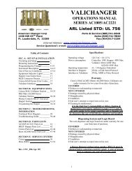
NOTCONNECTEDLCDDisplayRed LEDIndicatorNOTCONNECTED“Out ofService”NOTCONNECTEDMDBValidatorCompactHopperButton #1(UP)Button #2(DOWN)Button #3(SELECT)Figure 1 – Main Logic <strong>Board</strong> (MLB)STANDBY OPERATIONPower-ON the changer, and allow it to run throughits start-up procedure, which may take up to aminute or more, before attempting to changeanything. During this time, you may hear thehopper(s) or validator motors cycling as the MainLogic <strong>Board</strong> (MLB) checks them; this is normal.Once all motion has ceased, and all indicator lightsare showing a “Ready” condition, the changer is inits Standby state, ready to accept bills or coins. Inthis state, the MLB display’s backlight will be oncontinuously, and the screen will show the currentcount of total dollars changed by the machine(00000.00). Additionally, the board’s red LED willblink a heartbeat every second to indicate that theunit is getting power and functioning normally. (SeeFig. 1)ACCESSING THE PROGRAM MENUSYour changer comes preset with default operationalsettings that are easily reprogrammed to meet yourdesired application. Programming is done using thethree buttons and LCD display located on the MainLogic <strong>Board</strong> as an interface (See Fig. 1).When the unit is in the Standby mode, pressing the‘SEL’ (Select) button enters the Setup modeinitially, and then it selects and saves your choiceswithin the Setup mode menus that follow. Buttons#1 and #2 are used to move the cursor, and toincrease or decrease user-set values. Many of themenus contain submenus, which may be accessedby pressing the Select10button when the appropriate menu item isdisplayed, or highlighted. Choosing ‘Exit’ in anymenu will take the program out of Setup back toStandby mode. Note: Many of the menu itemscontain a series of settings. For example, the‘Accept’ submenu under ‘Bills’ contains six billdenominations to choose whether to accept ordeny. These settings must be done in sequenceall the way through for any changes to be saved.Choosing ‘Exit’ at any point in the middle of aseries will return the program to Standby modeWITHOUT saving any changes. Also, afterprogramming is complete and the changer isback in Standby mode, turn the MLB power OFFthen back ON again before resuming operation.The following sections describe the variousoptions available in the software, and should beused as a reference during initial setup andconfiguration. It may be helpful to follow alongin the Program Flow Chart as you read throughthe menu descriptions.SETTING BILL ACCEPTANCEBILLS:The first menu item contains settings that affectthe bill validator.Accept: This submenu is used to specify whichbill denominations will be accepted by thevalidator. Choose whether to accept (Y) or deny(N) each bill denomination in sequence. Note:The validator also has DIP switch settings forindividual denomination acceptance. Both thevalidator and the Logic <strong>Board</strong> must be set to‘Yes’ or ‘Accept’ for a bill to be accepted. Checkthe validator section in this manual forinformation on your particular validator (Factorysettings from <strong>American</strong> <strong>Changer</strong> enable all billson the validator’s DIP switches, so they should
not be changed; all settings can be made in theMain Logic <strong>Board</strong>). Not all validators can accept allbill denominations up to $100 bills.Security: This setting applies to ALL bills. Setwhether to use high or low security scanning of billsby the validator. High security scanning, basically,checks more bill parameters and makes it moredifficult to pass a counterfeit bill. For this reason,though, high security may require a “crisper” ornewer bill for acceptance, and may not accept anolder “tissue-paper”, yet legitimate, bill that lowsecurity might.SETTING COIN ACCEPTANCE (OPTIONAL)COINS:This Menu item only shows up if a ccTalk CoinAcceptor is present and set up in the Hardwaremenu (Refer to pg. 13 for Coin Acceptor setup).Similar to setting bill acceptance, the ‘Coins’ menuis used to specify which coin denominations will beaccepted. Denomination settings depend onwhether US or Canadian coins were selected duringCoin Acceptor setup. For US coins, choose to accept(Y) or deny (N) nickels through one-dollar coins.For Canadian coins, accept or deny 25 cent, onedollar,and two-dollar coins. Note: The Condor Plususes pulse communication, NOT ccTalk.SELECTING AN OPERATING MODEHARDWARE: MODE:The changer can be selected to run in any one offive distinct operating modes. Mode selection isdone in the sixth submenu of the ‘Hardware’ menu,‘Mode’. Which mode to select depends on how thechanger is to be used. Please read through thefollowing descriptions, and choose the one thatmatches the way you want your changer to besetup. Mode selection should be made PRIOR tosetting up the payouts in the ‘Payout’ menu,because the payout menu changes for differentmode settings.Simple Vending (S Vend): Vend tokens only ifmachine has one hopper, or vend tokens from theleft hopper and change from the right if themachine is equipped with two hoppers. If this modeis selected, the program prompts you to select thenumber of tokens to be dispensed, One or Many.For two hoppers, ‘One’ means that one token willbe dispensed, and change will be made for theremaining balance, if any. ‘Many’ means that thehopper will dispense as many tokens as possible forthe money denomination accepted, and change willbe made for the remaining balance, if any. Tokenand change values are set in the ‘Payout’ menu.For one hopper, since no change is available, thechanger defaults to ‘Many’, changing the fullamount to tokens. Discounts or bonus payoutsare not possible using Simple Vending mode.Game Tokens (GmeTkns): Select Game Tokensmode to vend tokens only. NOTE: This is themode to use if you would like to make use of“Party Tokens”, which can be user-set to payout as many as 999 tokens. Payouts per moneydenomination, and up to 4 different “PartyTokens”, can be set independently, giving theoption of including discounts or bonuses forcertain denominations at your discretion. Ifchanger is equipped with two hoppers, bothshould be filled with the same tokens.Simple <strong>Changer</strong> (S Chngr): This is the mostbasic changing mode. A coin or bill is fullychanged into the denomination(s) of coins in thehopper(s) without discounts or bonus payouts.This mode can be used with one or two hoppers.If two hoppers are installed, they can each befilled with the same or different denominationcoins to make change with. The program willprompt you to enter whether the coins in thehoppers are the same (Same) or different (Diff.)Payouts settings are per dollar. (Change valuesand payouts are set in the ‘Payout’ menu; seepgs. 12-13)Advanced <strong>Changer</strong> (A Chngr): Advancedchanging mode is designed for two hoppersonly, each filled with different coins. This is themost configurable changing mode, as it allowsindependent changing options to be set for eachcoin and bill accepted. Individual payouts fromboth the left and right hoppers can be set foreach money denomination, allowing for a broadvariety in the types of payouts that can be set,including discounts for certain bills and bonuses,if desired.Advanced Vending (A Vend): This mode is,basically, a further adjustable version of theSimple vending mode, adding the capability ofsetting individual payouts per each acceptedmoney denomination. When two hoppers areused for this mode, unlike in Simple vendingmode, you have the option of filling them withthe same or different coins (select ‘Same’ or‘Diff.’ after selecting this mode). If they are bothfilled with the same tokens, the changer worksthe same as with one hopper. If ‘different’ isselected, the left hopper should contain tokens,while the right should contain coins for change.All payouts are configurable for each acceptedmoney denomination; you set how many tokensand how much change is paid out for eachtransaction (see pgs. 12-13 for ‘Payout’ menuinstructions).11
PAYOUT OPTIONSPAYOUT:There are a total of eight different ways that thismenu can appear, as seen in the Program FlowChart on pgs. 6-7 in the row of boxes under the‘Payout’ box, depending on what Hardware Modethe unit is set to, the number of hoppers, and thetype(s) of coins or tokens in the hopper(s). If notalready done, please select an operating mode forthe changer PRIOR to completing the ‘Payout’settings (Refer to the Selecting an Operating Modesection).Simple Vending Mode (1 Hopper): Press Up orDown (buttons #1 or #2) to set the value of thetokens in the hopper. A token’s worth can be set toanywhere between 1¢ and $20. Press the Selectbutton to save the value chosen.Example: Set Token = $0.25 to pay out 4tokens per dollar.Simple Vending Mode (2 Hoppers): Select a valuefor the tokens in the left hopper (‘Token L’), andenter the denomination of the coins in the right sidehopper (‘Change R’). Both can be set to valuesbetween 1¢ and $20.Example: With the mode set to ‘many’, setToken L = $0.30, and Change R = $0.05 (fillthe right hopper with nickels). Inserting a $5bill will pay out 16 tokens ($4.80) and 4nickels ($0.20). With the mode set to ‘one’,the payout will be 1 token ($0.30) and 94nickels ($4.70) for the same $5 bill.Game Tokens Mode (1 or 2 Hoppers): If changer isequipped with two hoppers, both should be filledwith the same tokens for this mode. Here, set thenumber of tokens to be paid out per moneydenomination accepted, starting with the quarterand proceeding, in increasing order, all the way tothe $100 bill (Only the denominations that havebeen set for acceptance in the ‘Bill’ and ‘Coin’menus and on the validator will show up). Then,continue by setting the number of tokens to be paidout for up to 4 different “Party Tokens”. Press Up orDown (buttons #1 or #2), then Select to set thepayouts. Each number can be set to anywherebetween 0 and 999 tokens.Example: Set $Q = 1, $1 = 4, $5 = 22, and$TK1 = 100. This will pay out 4 tokens perdollar with a 2 token bonus for changing a $5bill, and 100 tokens upon acceptance of“Party Token” #1.Simple <strong>Changer</strong> Mode (1 Hopper, or 2 with samecoins): Enter the denomination of coins in thehopper(s). This value can be set to anywherebetween 1¢ and $20. Use the Up button to increasethe value and the Down button to decrease it, andpush the Select button to save.Example: Set Change = $0.25 to pay out 4quarters per dollar.Simple <strong>Changer</strong> Mode (2 Hoppers with differentcoins): Begin by entering the denomination of12coins in the left (‘Change L’) and right (‘ChangeR’) hoppers. These values can be set toanywhere between 1¢ and $20. Next, set thenumber of coins from each to be paid out perdollar for each changing operation. The lefthopper is first (‘Payout L’), then the right(‘Payout R’).Note: The ‘Payout’ settings override the‘Change’ value settings, so be sure to correctlyenter how many of each coin you wantdispensed per dollar.Example: Set Change L = $0.25, Change R= $0.05, Payout L = 3, and Payout R = 5 topay out 3 quarters and 5 nickels per dollar.Advanced <strong>Changer</strong> Mode (2 Hoppers w/ differentcoins): First, enter the denomination of coins inboth the left hopper (‘Change L’) and the right(‘Change R’). These values can be set toanywhere between 1¢ and $20. Then, set thenumber of coins to be paid out of each hopperper money denomination, starting with the lefthopper payout per quarter (‘$Q L’), then theright hopper payout per quarter (‘$Q R’), thenleft and right payouts per dollar, and so on upthrough payouts per $100 bill. Thosedenominations that are not enabled are skipped.Note: The ‘Payout’ settings override the‘Change’ value settings, so be sure to correctlyenter how many of each coin you wantdispensed per denomination.Example: To pay out exactly 5 nickels perdenomination, with the balance to be paidin quarters, the settings would be: ChangeL = $0.25, Change R = $0.05, $Q L = 0, $QR = 5, $1 L = 3, $1 R = 5, $5 L = 19, $5 R =5, $10 L = 39, $10 R = 5, etc…Advanced Vending Mode (1 Hopper, or 2 withsame tokens): Using the Up and Down buttons,set the value of the tokens in the hopper(s).They can be set to values between 1¢ and $20.Following this, enter the number of tokens to bedispensed for each accepted bill denominationstarting with $1 and increasing, in sequence, to$100. Any number between 0 and 999 can bechosen for each, giving you the option ofincluding discounts or bonus payouts starting at$1 bills.Example: Set Token = $0.50, $1 = 2, $5 = 12,and $10 = 25 to pay out 2 tokens per dollarwith a 2 token bonus for five dollar bills, and afive token bonus for ten dollar bills.Advanced Vending Mode (2 Hoppers: Tokens Land Coins R): This mode requires that the leftsidehopper contain tokens, and the right-sidehopper contain coins for change. First, selectthe value of the tokens in the left hopper(‘Token L’), and then enter the coindenominations in the right hopper (‘Change R’).Then, in sequence, enter the desired number ofeach to be paid out for each bill value acceptedby the validator. The program will prompt foreach value starting with the token payout perone-dollar bill (‘$1 L’) and change given (‘$1 R’).
This is followed by the token and change payoutper $2 bill (if enabled), and so on up through thepayouts per $100 bill. Note: The ‘Payout’ numbersoverride the ‘Token’ and ‘Change’ value settings, sobe sure to correctly enter how many of each youwant the changer to dispense per denomination.Example: To dispense two-dollar tokens andgive some change in quarters for every billaccepted, set Token L = $2.00, Change R =$0.25, $2 L = 1, $2 R = 0, $5 L = 2, $5 R = 4,$10 L = 4, $10 R = 8, $20 L = 9, $20 R = 8,etc….Once the payouts have been set, always run teststo be sure they are correct and how you want thembefore final installation of the changer. The settingscan be programmed and reprogrammed as much asneeded, and can be changed at any time to meetyour requirements.HOPPER SETUPHARDWARE: HOPPERS:The changer will arrive from the factory with thisinformation already programmed, so this menu willonly be needed if changes are to be made. Toaccess the ‘Hoppers’ menu, first enter the‘Hardware’ menu by highlighting it with the cursor,and pressing Select; it is the first submenu. Usethis menu to tell the Logic <strong>Board</strong> what types ofhopper(s) are installed inside the changer.ccTalk: Select this option if using one or morehoppers with a ccTalk serial interface to the MainLogic <strong>Board</strong> (MLB). Once selected, enter thenumber of ccTalk hoppers, one or two, to be usedin the changer. Note: Each Logic <strong>Board</strong> has thecapacity to control two ccTalk hoppers, left andright, but if only one is used, it must be pluggedinto the left-side connector (see Fig. 1 for theccTalk device connections on the MLB). FurtherNote: If your model changer has two Logic <strong>Board</strong>sand two hoppers, then only one hopper will becontrolled by each board; select ‘1’ as the numberof ccTalk hoppers on both boards.Compact: Highlight and Select this option if themachine has a Compact Hopper installed (see Fig. 1for the compact hopper connection on the MLB).COIN ACCEPTOR SETUPHARDWARE: COINACC:If the changer came from the factory with a coinacceptor already installed, this information willbe preprogrammed into the MLB, so this menuwill only be needed if changes are to be made.The second submenu inside the ‘Hardware’menu is the Coin Acceptor setup menu(‘CoinAcc’). Similar to the ‘Hoppers’ menu, thismenu is used to configure the Logic <strong>Board</strong> forthe use of a coin acceptor.ccTalk: This option should be selected if theinstalled coin acceptor communicates with theMain Logic <strong>Board</strong> using ccTalk serialcommunication protocol (see Fig. 1 for theccTalk device connections on the MLB; contactthe coin acceptor’s manufacturer or <strong>American</strong><strong>Changer</strong> if help is needed). After choosingccTalk, the program prompts for specification ofthe currency type that will be processed by thecoin acceptor. Choose either US or Canadiancoins.Pulse: If the installed coin acceptorcommunicates with the Logic <strong>Board</strong> using pulseprotocol, select ‘Pulse’ (the Condor Plus usesPulse communication). Following this, theprogram will request specification of the logiclevel used to enable the coin acceptor, high (Hi)or low (Lo) (for the Condor Plus, select high).Note: the Logic <strong>Board</strong> can only control one pulsedevice, so if a pulse validator is installed, apulse coin acceptor cannot be (see Fig. 1 for thepulse device connection on the MLB).None!: Select this option only if the changer isnot equipped with a coin acceptor.VALIDATOR SETUPHARDWARE: VALIDATOR:The changer will arrive from the factory withthis information already programmed, so thismenu will only be needed if changes are to bemade. Setup of the validator(s) is done usingthe third submenu, ‘Valid.’ inside the ‘Hardware’menu. The Main Logic <strong>Board</strong> can control up totwo validators, but only one of each type. Thetwo types are distinguished by their use ofeither MDB or pulse communication protocols tocommunicate with the MLB. The settings in thissubmenu tell the Logic <strong>Board</strong> how many of eachtype of validator, if any, are installed in thechanger.MDB: Select ‘MDB’, and then enter how manyMDB validators are installed in the changer,either one (1) or zero (None!) (see Fig. 1 for theMDB validator connection on the Main Logic<strong>Board</strong>)13
Pulse: Select ‘Pulse’, and then choose either one(1) or zero (None!) to specify the number of pulsevalidators that are inside the unit. If ‘1’ is chosen,then the program will further prompt for whetherthe validator is enabled using a logic-high (Hi) or alogic-low (Lo) signal; either must be chosen. Note:the Logic <strong>Board</strong> can only control one pulse device,so if a pulse coin acceptor is installed, a pulsevalidator cannot be (see Fig. 1 for the pulse deviceconnection on the MLB).ANTI-STRINGING PROTECTIONHARDWARE: STRING:The fourth submenu inside the ‘Hardware’ menu isused for setting up or disabling options that helpprotect the changer from “stringing”. Select‘String’, and then choose either to enable stringingprotection (Y), or to disable it (N). If Yes is chosen,there is a series of three settings that will follow,explained next, that together control the behaviorof the changer with regard to stringing.Max $: This setting is the maximum dollar amountthat can be accepted by the machine within theuser-set time limit (next setting) before triggeringthe anti-stringing protection. The dollar amount canbe chosen anywhere between $20 and $200 in $5increments.Max Time: The time entered here is the time limitfor the changer accepting the user-set maximumdollar amount (previous setting). If the changeraccepts the maximum dollar amount within theamount of time set here, anti-stringing protectionwill be triggered. The length of time can be set toanywhere between 5 and 120 minutes in 5 minuteincrements.Shut Off: This setting controls the anti-stringingprotection, which is the shutting down of thechanger for the time specified here. The changercan be set to shut down for 15, 30, 45, or 60minutes, or until the MLB is reset by turning thepower off then back on (‘Reset’).USING THE HOPPER DUMP FEATUREHARDWARE: DUMP:Enter this submenu to enable or disable the “dump”feature, which will automatically empty all of thecontents of the hopper(s). After entering the‘Hardware’ menu, scroll down and select ‘Dump’. Toenable the feature, choose Yes (Y), and to disableit, choose No (N). Note: choosing Yes will notinitiate a coin dump; it will only enable them tooccur.Using the DUMP Feature: The following willwork only if the Dump feature is enabled in the‘Dump’ menu.1. Open the changer door to give access to theMLB and the hopper(s).2. Place a suitable container in front of thehopper to catch the dispensed coins. On rearload models, the coins may have to bescooped out of the coin cup as they arebeing ejected.3. On the Main Logic <strong>Board</strong>, press and holdbuttons #1 and #2 (Up and Down)simultaneously, until the hopper(s) begin todispense their contents. They should onlyneed to be held down for a few seconds.4. Once the hopper(s) are emptying, they willcontinue to run until manually stopped bypressing the Select (SEL) button on the MLB.They may be stopped at any time, orallowed to run until empty.5. A count of the number of coins beingdispensed by each is displayed on the LCDdisplay. If the hoppers are completelyemptied, this count will show how manycoins were in each before dumpingcommenced.---[ END PROGRAMMING SECTION ]---FUNCTIONAL DESCRIPTION OF THE<strong>AC500</strong> SERIES CHANGERTo follow along with this walk-through of yourchanger, fill the hopper with coins and turn thechanger on.1. When power is applied the validator willcycle twice, and the red Out-of-Service lightflashes then goes out. The LCD screen onthe Main Logic <strong>Board</strong> (MLB) will display theSoftware version installed in the board’sEEPROM, and its backlight will be ONcontinuously. The small red status LEDabove the display will begin to blink once persecond in the Standby mode, waiting forsomething to happen.2. During the power-up mode the Main Logic<strong>Board</strong> will communicate with the validatorusing MDB or pulse protocol. During thistime the Display shows the current totaldollars changed count. The MLB establisheswhat type of validator is installed, andcommunicates the current program settingsand parameters that the validator needs toknow in order to function (type of bills toaccept, bill pulse value, etc.). The MLB thenasks the bill validator if it’s OK and ready toaccept bills, or if it has errors. This processtakes approximately 10-15 seconds.3. Also during the power up sequence, theMLB, using ccTalk, communicates with thecoin hopper. It is also setting up the sameparameters and requests as the billvalidator, but it is also informing the hopperwhat type of coins it will be paying (general14
size and thickness). Since all coins we vend arefrom 20-30mm, this rarely changes.4. When a bill is finally inserted into the validatorbill slot, the bill will be pulled inside. The MLBdisplay for the validator shows “BUSY” whilethe validator compares what the bill looks liketo examples in memory. After the bill isaccepted, the validator tells the MLB that it isOK to accept, and asks if it is OK to stack thebill. The MLB will then check the coin hopperstatus before sending an OK. The Validatorstacks the bill, but the MLB waits until theValidator sends a code stating the bill has beenstacked before proceeding.5. Now that the bill type accepted is stored in theMLB flash memory, the program reads thesettings for type and number of coins to bedispensed. The program then computes thepayout using the received bill type and the cointype(s) selected by the user, and divides thatnumber by the total coin hoppers functioning.This will be the payout for each hopper.6. The program then sends secure DATA words tothe hopper informing it of the amount of coinsto dispense.7. When the hopper is finished, it sends a differentDATA word to the MLB. The MLB then turns offthe “Busy” display, and the changer returns tothe STANDBY mode, with the red LED flashingonce per second, until another bill is inserted.OUT-OF-SERVICE CONDITIONSOut-of-Service conditions occur in the changer forthe following reasons: blown fuses, validator faults,coin acceptor faults, or hopper faultsBlown Fuse: An AC power spike in line voltage ora bad transformer on the Power Supply board cancause a blown fuse. If the primary fuse blows, theindication is that the green LED on the powersupply will not light.1. Replace the fuse. If the green LED now lightsthen there was a spike.2. If it does not light and the fuse blows again,disconnect the hopper and validator connectorsand try again. If the green LED stays lit,reconnect each component one at a time untilyou find the one blowing the fuse.3. If the fuse still blows with all componentsremoved from the MLB, the power transformeris shorted. To test the transformer, use amultimeter set for ohms and measure acrossthe primary (40ohms) and the secondary(1.5ohms).Validator Faults: When a validator fault occurs,the validator’s EEPROM shuts down the validatorand sends an error code to the Logic <strong>Board</strong>’s LCDdisplay. The Out-of-Service light on the front of themachine will illuminate for a validator fault.1. Validat. Full – The Bill Stacker is full of billsand should be emptied.2. Validat. Motor – Motor failure. Either theStacker or Transport motor has failed; replacethe unit.153. Validat. Sensor – One of the sensors insidethe validator has failed. Check for a jammedbill; if that is not the cause, repair or replacethe validator.4. Validat. Checksum – Checksum failure.The validator’s Logic <strong>Board</strong> programminghas been corrupted; repair or replace thevalidator.5. Validat. CashBox – The Bill Stacker hasbeen removed from the validator and shouldbe replaced.6. Validat. NoComm – There is acommunication failure between thechanger’s Main Logic <strong>Board</strong> (MLB) and thevalidator. This may be a temporary conditionwhile one of them is completing some task,or the cable harness may be loose orunplugged, or the validator may need to berepaired or replaced.7. Validat. Disabled – The MLB cannot enablethe validator, due to an internal error insideof the validator. This may be acommunication issue, and may betemporary.8. Validat. String – The changer’s Anti-Stringing protection has shut down themachine’s operation. Basically, more moneyhas been paid out in less time than allowedby the system’s settings (see pg. 14 forAnti-Stringing protection setup). Wait theallotted time, or reset the MLB to resumeoperation.9. Validat. Pulse – The pulse validator beingused has been disabled. Check the unit andrepair or replace as necessary.10. Busy – This message is displayed wheneverthe validator is in the process of validating(accepting) or stacking a bill.Coin Acceptor Faults: The following CoinAcceptor faults are only for changers equippedwith a Money Controls SR3 Coin Acceptor usingccTalk serial communication protocol. The Outof-Servicelight on the front of the machine willNOT illuminate for a Coin Acceptor fault, but theerror message will be displayed on the LCDdisplay.1. CoinAcc. NoComm – There is acommunication failure between thechanger’s Main Logic <strong>Board</strong> (MLB) and thecoin acceptor. This may be a temporarycondition, or the cable harness may be looseor unplugged, or the coin acceptor may needto be repaired or replaced.2. CoinAcc. EEPROM – The EEPROM on thecoin acceptor’s logic board has an error.Repair or replace the unit.3. CoinAcc. Coils – There is a general fault inthe unit’s inductive coils. Check the coinpath, or “flight deck”, for dirt or anobstruction. If nothing is found, unit mayneed servicing or replacement.4. CoinAcc. CreditS – The coin acceptor’sCredit Sensor is either blocked or faulty.Check for a jammed coin on the “credit”
side, or else the unit may need repair orreplacement.5. CoinAcc. Piezo – The coin acceptor’s PiezoSensor is experiencing a fault. Unit may needrepair or replacement.6. CoinAcc. RejectS – The coin acceptor’s RejectSensor is either blocked or faulty. Check for ajammed coin on the “reject” side, or else theunit may need repair or replacement.7. CoinAcc. TempS – The coin acceptor’sTemperature Sensor is experiencing a fault.Unit may need repair or replacement.8. CoinAcc. TempHigh – The operatingtemperature of the coin acceptor is abovespecified limits. Locate the cause of the hightemperature and remedy the situation. Ifnothing is found, the temperature sensor mayhave failed, or the unit may need servicing orreplacement.Hopper Faults: Hopper faults occur for a varietyof reasons, but the most common in any coinmachine is always low coins. Any of the hopperfaults will cause the Out-of Service light on thefront of the machine to illuminate. For thefollowing, if two hoppers are installed in themachine, X = L (left) or R (right).1. HopperX NoComm – The changer’s Main Logic<strong>Board</strong> is unable to communicate with thehopper. This may be a temporary condition, orthe cable harness may be loose or unplugged,or the hopper may need to be repaired orreplaced. Note: If using only one hopper, itmust be plugged into the left-side connector(see Fig. 1).2. HopperX NoPay – This code signifies that apayout signal was sent to the hopper, but thehopper did not dispense any coins/tokens.Check the hopper for a possible coin jam, exitblockage, or other mechanical fault. If nothingcan be found, have the unit repaired orreplaced. Note: If using two hoppers and oneof them fails to pay out, the other hopper willmake up the difference, if it can.3. HopperX OptoBlkd – An optical sensor nearthe exit window is being blocked. The exit pathmay be obstructed, or the Optic <strong>Board</strong> may bebad. Repair or replace.4. HopperX Current – The maximum currentlevel for the hopper is being exceeded. Inspectfor a jammed coin preventing the coin ElevatorTrack from moving, or a stalled or shortedmotor. Repair or replace the hopper.5. HopperX Fraud – The changer may bebeing defrauded. Inspect for a jammed coinor other obstruction near exit window;repair or replace the hopper.6. HopperX TimeOut – The coins/tokens werenot dispensed from the hopper in thespecified time. Check the hopper for anycoin jams or mechanical obstructionspreventing coins from exiting. Also checkthat the compact hopper harness is securelyconnected to the correct MLB connector(refer to fig. 1 on pg. 10) on one side, andto the white 4-pin connector, located underthe coin chute on the bottom front of theCompact Hopper, on the other. Have theunit repaired or replaced.7. HopperX Low – This is the most commonerror; it signals Low Coins in the hopper.Refill the hopper with coins or tokens. If youhave enough coins in the hopper to coverthe gold low-level sensing plates and youare still getting this message, try thefollowing:A. Ensure the coins have not bridged in theextension on top of the hopperpreventing them from falling down intothe hopper.B. Clean the bottom gold plates of thehopper with EMERY cloth or finesandpaper. Refill the hopper and tryagain.C. Using an ohmmeter, check thecontinuity of the hopper harness fromthe 12-pin connector back to the logicboard. You should get 0 ohms for eachline.If none of this works, the unit may needrepair or replacement.EQUIPMENT INDICATOR LIGHTSMain Logic <strong>Board</strong>:1. Red LEDA. Heartbeat – 24, 5, and 3.3Vdc present;the changer is operating normally.2. LCD Display BacklightA. ON Steady – Normal operation; thisapplies to both Standby andProgramming modes.B. Blinking – Error condition present; thebacklight blinks synchronously with theRed LED (see pgs. 15-16 for errormessage descriptions).Validator logic board:1. LEDA. On Steady - Standby Mode, waiting forbill insertion.B. Flashing - Error mode, see page 17 or24 for error code information.C. Off - The changer “Out-of-Service” LEDis lit.16
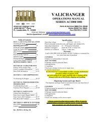
HOPPER COIN/TOKEN SIZESCompact Hoppers can be configured to pay outcoins in the diameter range 16.25 – 31.00mm andwithin the thickness range 1.25 – 3.2mm. However,each coin needs to be qualified on an individual coinbasis.A nickel is approximately 21 mm, a quarter isapproximately 25mm, a new $1 coin isapproximately 26.5 mm, and a Susan B.Anthony dollar is approximately 28mm indiameter.<strong>American</strong> <strong>Changer</strong> offers Compact Hoppers that willdispense quarter-size coins and ones that willdispense $1-coin-size coins. Contact <strong>American</strong><strong>Changer</strong> with any questions, or to order a differentHopper configuration.Hopper Coin Bin(Dump coins into thishole; 40 – 1000, min.to max.)Compact Hopper harness:Connector J1Pin #1 - Motor GroundPin #2 - Motor Power (+24VDC)Pin #3 - Chassis GroundPin #4 - Sensor APin #5 - Low Coin SensorPulse Device harness:Connector J11Pin #1 - +24VDCPin #2 - Bill InPin #3 - FailPin #4 - EnablePin #5 - GroundPin #6 - Ground“Out-of-Service” Light harness:Connector J2Pin #1 - +24 VDCPin #2 - GroundCOINCO MAG52SA SERIES ERROR CODESFlash codes 1-18 may appear during normalservicing of the MAG52. If more than one erroror condition exists, the lower number flash codewill appear until its respective error or conditionis corrected. The left and right sensorsreferenced below are given viewing the MAG52from the front.Low CoinSensing PlateContactsMAIN LOGIC BOARD CONNECTORPIN DEFINITIONSMDB Validator harness:Connector J12Pin #1 - +24 VDCPin #2 - GroundPin #3 - Data Pin, Master TransmitPin #4 - Data Pin, Master ReceiveCoinOutputChute# of Flashes Description of Flash Codes1 Bill Box Full2 N/A3 Check Bill Path4 All Bill Accept Switches are OFF5 Check Optical Sensors6 Stacker Motor/Home Sensor7 Transport Motor/Encoder Sensor8 N/A9 EEPROM Check Sum Error10 RAM or ROM Check Sum Error11 Center Optic Sensor12 Right Optic Sensor13 Left Optic Sensor14 N/A15 Right Position Sensor16 Left Position Sensor17 Lower <strong>Board</strong> Anti-Stringing Lever Sensor18 N/AccTalk Device Harnesses:Left Side (Single Hopper) – J3Right Side – J8Pin #1 - GroundPin #2 - +24 VDCPin #3 - +5 VDCPin #4 - No ConnectionPin #5 - Data Line (Tx & Rx)Pin #6 - Select (+24VDC) Right OnlyPin #7 - Ground17
COINCO MAG52SAVALIDATORSECTIONPAGERemoving the Bill Box 19Removing a bill jam 19Setting the bill types accepted 20-21Cleaning the sensors 21-22Cleaning a salted unit 22Replacing the belts 23Troubleshooting & Error Codes 2418
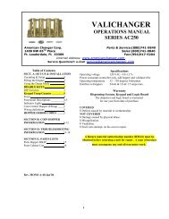
Removing the bill box.To remove the 500 bill stacker from the CoinCo validator, follow the picture below.REMOVING A BILL JAMFrom time to time a foreign object or ripped bill will become caught in the validator. Follow thepicture below to remove the item.19
SETTING THE BILL ACCEPT DIP SWITCHES20
(FACTORY DEFAULTSETTINGS)CLEANING THE BILL VALIDATORRefer to the pictures and the procedure on the next page to clean the bill validator every 4-6months.21
MAGPRO CLEANING: IF ANY OF THESE PROCEDURES ARE PERFORMED TO YOUR VALIDATOR AFTER IT ISRETURNED UNDER A WARRANTY REPLACEMENT, YOU WILL BE SUBJECTED TO A $65.00 LABOR FEE.CLEANING AND MAINTENANCE:Note: Petroleum-based cleaners and freon-based propellants can damage plastic and some electronic components. Scouringpads and stiff brushes may harm the protective conformal coating on the circuit boards and can mar the plastic. These itemsshould never be used when cleaning the MAGPRO bill acceptor.The MAGPRO should be cleaned every 7,000 bills orevery 4 -6 months (or as needed, depending on theenvironmental conditions of the location). Dust canbe removed with a soft brush or cloth or it can beblown out using compressed air.Procedure:1. Disconnect power from the bill acceptor.2. Remove the bill box and use a soft cloth to wipe thedust from around the intermediate frame and stackerplate.3. Remove the lower track.4. Using compressed air or a soft brush, blow or brushthe dust off of the optic sensors and out of the recessedsensor openings.5. Remove dust from around the belts and wheels on thelower housing and the sensors on the upper sensorboard. The upper sensors are located directly above thelower housing sensor when the lower housing is installed.6. The bill path can be cleaned to remove further dirtand oil using a soft cloth moistened with a mild soap andwater solution.7. Clean the magnetic head using a swab and isopropylalcohol.8. Once the lower housing is dry, place it back into themainframe so that the tab on the bottom locks into place.9. Blow the dust out of the encoder wheel and itssensors. (It may be necessary to extend the stacker plateto access the encoder wheel. Supplying power to the unitmomentarily can do this, so that the stacker plateextends.)10. Remove dust from the transport belt areas and fromany other places of build up.11. Remount the bill box.12. Apply power and insert bills to verify that the unit isfunctions property.MAGPRO CLEANING PROCEDURE FOR SALT WATERPOLLUTED UNITS:Note: Petroleum-based cleaners and freon-basedpropellants can damage plastic and some electroniccomponents. Scouring pads and stiff brushes may harmthe protective conformal coating on the circuit boards andcan mar the plastic. These items should never be usedwhen cleaning the MAGPRO bill acceptor.Procedure:1. Remove power from the bill acceptor.2. Remove the bill acceptor from the vending machine.3. Open the bill box lid and verify that the stacker plateis in the stand-by/home position. If it is not in thehome position, apply power and observe that thestacker plate returns home.Warning: If moisture is present, allow the unit to drythoroughly before applying power to avoid possible shockhazard. If the stacker plate does not return to the homeposition, remove power and carefully remove the bill boxto avoid damaging the bill box and/or stacker plate.4. Remove the lower housing.5. Remove the bottom cover from the lower housing.6. Run hot water (1101/4-1401/4F) over the lowerhousing from the top and bottom. Using a soft brush,gently clean any residual salt. Use a soft absorbentcloth to clean any residue off the lower housing. Ifthe transformer gets wet, allow the unit to dry for 24hours before applying power.7. Remove the front mask. Using hot water and a softbrush, clean the front mask, upper sensor board,main frame anti-pullback levers and position sensormount.Caution: The motors are not protected from water,therefore the unit must be held in a manner that preventswater from running over the intermediate frame crossbar.8. Remove the position sensor cover on the crossbar andcarefully lift the LED from its mount. (Early models only.)Caution: Protective coating on the LED leads should notbe damaged. Clean all salt residue from the mount,sensor hole and detector area.The detector can be seen through the sensor hole, and islocated in the chassis. Replace the position sensor cover.(Early models only.)9. Verify that the anti-pullback levers move freely andthat the spring returns them to their open position.10. Allow the unit to dry thoroughly.11. Clean the magnetic head using a swab and isopropylalcohol.12. Replace the front mask13. Replace the lower housing cover.14. Replace the lower housing into the main frame.15. Remount the bill box.16. Apply power and insert bills to verify that the unit isfunctioning properly.6 OR 7 ERROR CODE FLASHESThe cleaning procedure for this common occurrence islisted below. Just follow these steps.1. If this code has occurred on a new machine or onethat the validators DIP switches were just changed,Ensure that all the white plugs on the side of thevalidator board away from the red LED are pluggedin securely.2. Remove the bill box.3. Turn the <strong>Changer</strong> ON then OFF in an attempt to stopthe metal push plate so that it COASTS into the fullyoutward position.4. Using an air compressor or a can of compressed airblow out the area behind the push plate until it iscompletely free of all dust and lint.5. Turn the changer power back on so that the pushplate returns to the inward position. If the sameerror code persists, repeat steps 1 - 3 concentratingon the top center area behind the plate.6. Replace the bill box.22
REPLACING THE BELTSEvery 2-3 years the belts on the CoinCo will wear out. To replace them, remove the validatorcomponents down to the picture show. Refer to the parts diagram at the end of the manual forhelp getting to this point.23
MAG TROUBLESHOOTING GUIDEThis Troubleshooting Guide is intended to helplocate problems within the bill acceptor. If a billacceptor cannot be repaired by following thisguide, return the unit to <strong>American</strong> <strong>Changer</strong> or thenearest Coinco Service Center for repair alongwith a complete description of the problem youare having with the bill acceptor.Logic troubleshooting minimizes the time spent inremoving and replacing parts that are notdefective. Some failures are caused by minorproblems such as dirt or loose/faulty connections.Please check the following before replacing anyparts:• Clean any dirt or dust from the bill path.• Coin changer inventory tubes are filled totheir correct levels.• Connectors are inserted correctly.• Connector pins are not bent or broken.• All wires are properly secured.MAG DIAGNOSTIC CODESTroubleshooting can be done by reading thenumber of flashes or blinks of light from the LEDlocated inside the logic board cover. Since the redLED is normally ON, the number of flashes is thenumber of times it blinks OFF. These flashes canbe seen on the side of the logic box.Diagnostic codes 2, 8, 14, and 18 are not used.Codes 1, 3, 4, 5, 15, and 16 may appear duringnormal servicing of the MAG. If the MAG isflashing a #5 code, turn off power to the MAG for10 seconds. Reapply power to the MAG anddiagnostic codes 6, 7, 9, 10, 11, 12, 13, and 17will appear for approximately 30 seconds. After30 seconds these codes will revert back to the #5code. If more than one error exists, the lowernumber code will appear until its condition iscorrected. The left and right sensors referenced inthe code descriptions are given viewing the MAGfrom the front.24
TECHNICAL FLOW DIAGRAMBefore starting this procedure, ensure the changer is plugged in, the ON/OFF switch is ON, the hopper is full of coins, and all wireharnesses are connected securely and correctly. The wires exiting the red connectors should point away from the board!25
TROUBLESHOOTING GUIDETO USE THE TROUBLESHOOTING GUIDE, MATCH UP THE PROBLEM, THEN FOLLOW THESOLUTION SUGGESTIONS. After every step try operating the changer to see if the problem has been solved.PROBLEM:A. The changer is completelydead. (The green LED on thePower Supply <strong>Board</strong> is not lit.)B. The “Out-of-Service” LEDis lit. The Main Logic <strong>Board</strong>is displaying a “HopperXLow” error message.C. The “Out-of-Service” LEDis lit. The MLB is displayingany other error message.D. The green LED on the PowerSupply <strong>Board</strong> is lit, but thereis no red “heartbeat” LED onthe Main Logic <strong>Board</strong>.E. The bill validator will not pullin the bill and the “Out-of-Service” LED is not lit.FOR TECHNICAL SERVICE OR TOOBTAIN A RETURNAUTHORIZATION NUMBER CALL(888) 741-9840SOLUTION:1. Ensure the changer is plugged in.2. Ensure the ON/OFF switch is rocked to the ON (I) position (up).3. Unplug the female end of the line cord from the main logic board ACconnector and plug it in again tightly.4. Measure the AC voltage at the outlet or check the breaker/fuse box.You can also plug another item into the AC wall outlet to ensurethere is power present at the outlet.5. Inspect the AC line cord for cuts or abrasions.6. Check the fuse on the Power Supply <strong>Board</strong>.7. Replace the line cord.8. Replace the Power Supply <strong>Board</strong>.1. Ensure the hopper is not out of coins. (There should be enoughcoins in the hopper to cover the gold low-level contact plates.These plates are located at the bottom of the hopper where you pourthe coins.)2. Locate the Compact Hopper’s wiring harness, and make sure that itis plugged all the way in to the correct Main Logic <strong>Board</strong> connector(refer to fig. 1 on pg. 10).3. Ensure that the brown and white wires of the hopper harness aresecurely connected to the Low Coin Sensing Plate contacts.4. Check the continuity of the hopper harness back to the Main Logic<strong>Board</strong>. You should get zero (0) ohms.5. Clean the gold contact plates with steel wool or fine sandpaper.6. Replace the hopper wire harness.7. Replace the hopper.1. Refer to the “Out-of-Service Conditions” section on pgs. 15-16 for a listing of all software error codes and commonsolutions.1. Bad 5vdc or 3.3vdc regulator on the main logic board.2. The hopper is shorted, or its motor is stalled.3. Replace main logic board.4. Fix the coin jam in the hopper; Repair or Replace hopper.1. Ensure the orange and brown wires going to the “Out-of-Service”LED are connected fully to the LED and to the MLB connector.2. Check for 24vdc on the orange and brown wires. If it is present, theLED is bad and needs to be replaced.3. Replace the main logic board.4. Replace the bill validator.5. Replace the validator wire harness.ANY REPAIR RETURNED WITHOUT ARETURN MATERIAL AUTHORIZATIONNUMBER (RMA#) WILL BE REFUSED!!26
TROUBLESHOOTING GUIDETO USE THE TROUBLESHOOTING GUIDE, MATCH UP THE PROBLEM, THEN FOLLOW THESOLUTION SUGGESTIONS. After every step try operating the changer to see if the problem has been solved.PROBLEM:SOLUTION:F. The bill validator pulls inthe bill, but rejects it everytime.G. The changer is giving thewrong payouts.H. The bill validator’s redstatus LED is on steady butit still will not accept thebill.1. Clean the validator (refer to pgs. 21 and 22).2. Remove the lower housing of the bill validator. Ensure the centerwheel spins freely. Push straight down on it slightly to loosen.3. Make sure that the bill denomination being rejected is enabled byBOTH the validator AND in the Main Logic <strong>Board</strong> program. Refer topgs. 20 and 21 for the validator, and pgs. 10-11 for the MLB.4. The validator may be flashing an error code. Open the changer doorand check the validator’s LED indicator. Error codes and descriptionsare listed on pgs. 17 and 24.1. The Main Logic <strong>Board</strong>’s user-programmed settings for changer‘Mode’ and/or ‘Payout’ are incorrect. Refer to the section“Programming the <strong>AC500</strong> Series <strong>Changer</strong>” on pages 4-14 of thismanual for detailed instructions on how to reprogram the changer’soperation.1. Pull out the lower housing, referring to pg. 19 for instructions, andlook for something obstructing the bill path (i.e. gum, papers, tickets,coins, etc.).2. Open up and look inside the plastic Logic <strong>Board</strong> box on the side of thebill validator. Ensure that all the wire harness plugs are plugged firmlyinto their white female sockets.FOR TECHNICAL SERVICEOR TO OBTAIN A RETURNAUTHORIZATION NUMBERCALL (888) 741-9840ANY REPAIR RETURNED WITHOUT ARETURN MATERIAL AUTHORIZATIONNUMBER (RMA#) WILL BE REFUSED!!27
MONEY CONTROLS COMPACT HOPPER PARTS LIST28
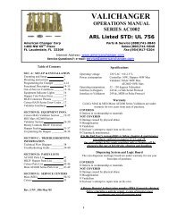
<strong>AC500</strong> CABINET PARTS BREAKDOWN#2#1#3#4#7#5#6#8<strong>AC500</strong> CABINET PARTS#1 AC5010 - <strong>AC500</strong> CABINET W/DOOR, LOCK NUT ASSY., & COIN CUP#2 AC1065 - MAIN LOGIC BOARD W/ LCD DISPLAYAC1066 - AC-01 POWER MODULE BOARD#3 AC5040.1 - MONEY CONTROLS COMPACT HOPPER#4 AC5081 - <strong>AC500</strong> FULL LEXAN FRONT STICKER#5 AC5080 - SCREW-IN “T” HANDLE#6 AC1093 - LOCK AND 2 KEYS#7 AC9002 - COINCO MAG52SA (PRO) BILL VALIDATOR#8 AC5010.1 - DOOR FOR THE <strong>AC500</strong>OPTIONAL PARTS (NOT SHOWN)AC1051 - TWO OUTLET SURGE PROTECTORAC1052 - FOUR OUTLET SURGE PROTECTORAC1091 - TILT ALARM ONLYAC5070 - BASE / PEDESTALAC5075 - HEADERAC5040.2 - COMPACT HOPPER FOR $1 COINS29
COINCO PARTS LISTMOUNTING ASSEMBLY PARTS BREAKDOWNPICTURE ##1#2#3#4#5#6#7PART #MP90-1-1MP90-1-2MP90-1-3MP90-1-4MP91-1-5MP90-1-6MP91-1-7DESCRIPTIONMachine Screw“Snack Mask” Black PlasticMachine ScrewMain Frame, PlasticMask Gold Mounting BracketBill grounding springMachine Nut30
COINCO PARTS BREAKDOWNBELTSONLY!MP91-2-10PICTURE ##1#2#3#4#5#6#7#8#9#10#10#11#12#13#14#15#16PART #MP90-2-1MP90-2-2MP90-2-3MP90-2-4MP91-2-5MP90-2-6MP90-2-7MP90-2-8MP90-2-9MP90-2-10MP91-2-10MP90-1-11MP90-2-12MP90-2-13MP90-2-14MP91-2-15MP91-2-16DESCRIPTIONBottom Lower Housing CoverTransformer holding hose120VAC TransformerLower Spring, Anti-Cheat LeverLower Mounting, Anti-Cheat LeverLower Anti-Cheat LeverLower Housing Assembly, CompleteBelt, CenterLower Anti-Cheat Assembly, CompletePlastic Wheels & Rubber BeltsRubber Belts ONLY (Each)Shaft, DriveSpring, MAGScrew, #4, PlasticRoller, IdlerSensor <strong>Board</strong>, LowerPulley & Hub Assembly, Complete31
COINCO PARTS BREAKDOWNPICTURE ##1#2#3#4#5#8#9#10#11#13#14#15#16#17#18#19#21PART #MP90-3-1MP90-3-2MP91-3-3MP90-3-4MP90-3-5MP90-3-8MP90-3-9MP90-3-10MP90-3-11MP90-3-13MP90-3-14MP91-3-15MP90-3-16MP90-3-17MP90-3-18MP90-3-19MP90-3-21DESCRIPTIONDust CoverUpper Transport & Hub Assembly, CompleteMotor, Transport & Gear Assembly CompleteWheel, EncoderStacker, Push-Plate AssemblySpring, Belt TensionMotor, Stacker Assembly CompletePulley, IdlerLower Transport Pulley & Hub AssemblyBelt, Upper HousingFrame, Upper HousingSensor <strong>Board</strong>, Upper HousingUpper <strong>Board</strong> ClipWire ClipShaft, PulleyShaft, Wheel<strong>Board</strong>, Stacker32
COINCO PARTS BREAKDOWNMP90-4-IF43PICTURE ##1#2#3#4#5PART #MP90-4-1MP91-4-2MP90-4-3MP90-4-4MP90-4-IFDESCRIPTIONLid, Logic board BoxBody, Logic board BoxMain Logic <strong>Board</strong>Sticker, Serial Number / WarrantyIntermediate Frame with Bearings33
Arizona3226 S. Fair LaneTempe, AZ 85282Phone: 602-431-0632Chris MattinglyCalifornia11618 E. Washington Blvd.Suite # JWhittier, CA 90606Phone: 562-692-3059FLORIDATampa6704 Benjamin RoadSuite 200Tampa, FL 33634Phone: 813-249-7338Bob WilcoxFt. Lauderdale<strong>American</strong> <strong>Changer</strong>1400 NW 65 th PlaceFt. Lauderdale, FL 33309888-741-9840RMA # NeededGeorgia4215 Wendall Dr SWSuite # EAtlanta, GA 30336Phone: 404-691-2777Chuck CrockettIllinois862 Eagle Dr.Bensenville, IL 60106Phone: 630-860-2650Mike DurecLouisiana524 Elmwood PkwySuite 190Harahan, LA 70123Phone: 504-734-0280Frank CaseMaryland6655 Amberton DriveBay “L”Baltimore, MD 21227Phone: 410-379-2680Bill LeJuneMassachusetts60 Prospect StreetWaltham, MA 02453Phone: 781-894-4525Kevin ColeMissouri1236 Dielman Industrial CTSt Louis, MO 63132Phone: 314-725-0100Charlie PaviaOhio225 Corporate CourtSuite IFairfield, OH 45014Phone: 513-874-4460Joe SteddomTEXASDallas3031 Quebec StreetSuite 115Dallas, TX 75247Phone: 214-638-3970Houston2500 Central ParkwaySuite “K”Houston, TX 77092Phone: 713-683-6558Steve TenBargeWashington1020 Industrial DriveBldg. 32Seattle, WA 98188Phone: 206-575-1999Carl Goodson34