
You also want an ePaper? Increase the reach of your titles
YUMPU automatically turns print PDFs into web optimized ePapers that Google loves.
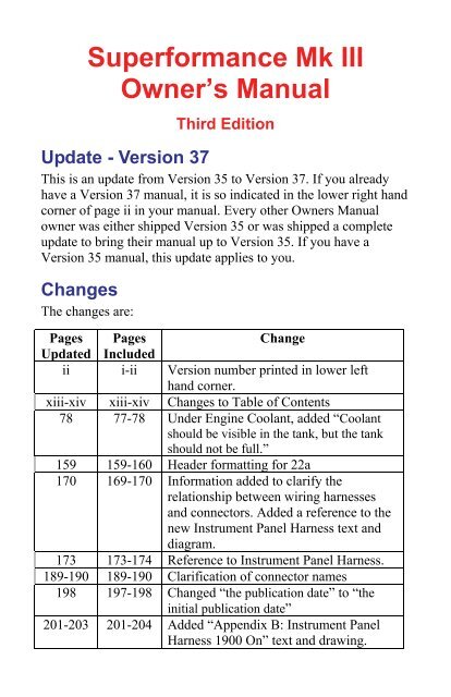
Superformance Mk IIIOwner’s ManualThird EditionUpdate - Version 37This is an update from Version 35 to Version 37. If you alreadyhave a Version 37 manual, it is so indicated in the lower right handcorner of page ii in your manual. Every other Owners Manualowner was either shipped Version 35 or was shipped a completeupdate to bring their manual up to Version 35. If you have aVersion 35 manual, this update applies to you.ChangesThe changes are:Pages PagesChangeUpdated Includedii i-ii Version number printed in lower lefthand corner.xiii-xiv xiii-xiv Changes to Table of Contents78 77-78 Under Engine Coolant, added “Coolantshould be visible in the tank, but the tankshould not be full.”159 159-160 Header formatting for 22a170 169-170 Information added to clarify t<strong>here</strong>lationship between wiring harnessesand connectors. Added a reference to thenew Instrument Panel Harness text anddiagram.173 173-174 Reference to Instrument Panel Harness.189-190 189-190 Clarification of connector names198 197-198 Changed “the publication date” to “theinitial publication date”201-203 201-204 Added “Appendix B: Instrument PanelHarness 1900 On” text and drawing.
PrintingThe Owners Manual original and this update were written in5.5" by 8.5" format, the standard size for a Superformance OwnersManual. Your Owners Manual was scaled up to 8.5" by 11" whenprinted.To print this update in 8.5” by 11” size in Adobe Reader or AdobeAcrobat:1. Click on File -> Print from the menu bar.2. In the Print dialog box, set Page Scaling to Fit to Paper or Fitto Printable Area and check Auto-rotate and Center.3. Click on OK.Both sides of the updated pages are included in case you printdouble sided.
Authorized DealerSuperformance Chassis Number: __________________________Model: _______________________________________Color: _______________________________________Stripes: _______________________________________Purchased by: _______________________________________Purchase Date: _______________________________________Page i
Superformance® Mk III Owners Manual Third EditionSuperformance® is a registered trademark of Superformance LLC.This document is copyright © 2009-2010 byMichael H. Stenhouse. Do not reproduce by any means includingelectronically without specific written permission on a case by casebasis.Portions of this document have been obtained from other sourcesby permission and remain the property of those sources.Michael H. Stenhouse, Ph.D.<strong>Second</strong> <strong>Strike</strong> LLC, the Superformance Owners GroupDavidson NC 28036-4600www.<strong>Second</strong><strong>Strike</strong>.comPage iiVersion 2010.37
16. Alternator Terminals (Eye Rings)........................................................... 15617. Solenoid Terminals - 5mm Eye Rings .................................................. 15718. Reverse Switch - on Gear Box.............................................................. 15719. Neutral Safety Plug................................................................................. 15720. Multi-Pin Plug - Fuse Box to Front Harness......................................... 15821. Power Supply in Fuse Box - 5 mm Eye Ring Terminal ........................ 15922a. Ignition Module Plugs (on Fuse Box Loom)......................................... 15922b. Ignition Module Plugs (on Module)...................................................... 15923a. Ignition Module Plugs (on Fuse Box Loom)......................................... 16023b. Ignition Module Plugs (on Module)...................................................... 16024. Multi-Pin Plug - Fuse Box to Dashboard.............................................. 16125a. Rear Loom to Fuse Box (in Fuse Box).................................................. 16225b. Fuse Box to Rear Loom (in Fuse Box) ................................................. 16226a. Rear Loom to Fuse Box (in Fuse Box Loom) ....................................... 16226b. Fuse Box to Rear Loom ........................................................................ 16327a. Number Plate Plug (on Rear Loom in Boot) ......................................... 16327b. Number Plate Plug (on Light in Boot) .................................................. 16328. Hard Top Interior Lamp Plug (In Boot by Roll Bar).............................. 16329. Rear Loom Earth.................................................................................... 16330. L/H Rear Indicator Terminals - Spade Connectors ............................... 16431. R/H Rear Indicator Terminals - Spade Connectors............................... 16432. L/H Tail Light Terminals - Spade Connectors...................................... 16433. R/H Tail Light Terminals - Spade Connectors...................................... 16434. Reverse Light Terminals - Spade Connectors....................................... 16435. Electric Fuel Pump Plug on Rear Loom.................................................. 16536. Fuel Tank Sender Terminals................................................................... 16537. Seat Belt Buzzer ..................................................................................... 16538. Radiator Thermo Switch Terminals........................................................ 16539. Wiper Harness to Wiper Motor Connectors - Sealed to Motor............... 16640. Wiper Harness Plug to Fuse Box Harness .............................................. 16641. Fuse Box Loom Plug to Wiper Motor Harness....................................... 16742. Heater Box Plug Connector into Dash Loom.......................................... 16743. Dash Loom Plug to Heater Box Plug...................................................... 16744. Indicator Stalk to Fuse Box..................................................................... 16845. Fuse Box Plug to Indicator ..................................................................... 168Wiring Diagrams 1900 On ..............................................................169Central Electrical Tray ........................................................................... 171Central Electrical Tray Harness Routing................................................ 172Instrument Panel Harness....................................................................... 173Front Harness ......................................................................................... 173Rear Harness .......................................................................................... 174CKT01 Low Brake Fluid Buzzer Circuit ............................................... 175CKT02 Turn Signal, Blower Motor Circuit ........................................... 176CKT03 Sidelight, Meter Lighting Circuit .............................................. 177CKT04 Headlight Circuit ....................................................................... 178CKT05 Horn Circuit, Brake Lights........................................................ 179CKT06 Radiator Fan Circuit .................................................................. 180CKT07 Alternator Warning Light Circuit.............................................. 181Page xiii
CKT08 Ignition Coil Supply, Starter Circuit.......................................... 182CKT09 Ignition Module Circuit............................................................. 183CKT10 Wiper Motor, Reverse Light Circuit.......................................... 184CKT11 Fuel Level Circuit...................................................................... 185CKT12 Fuel Pump Circuit ..................................................................... 186CKT13 Seat Belt Buzzer Circuit (Australia).......................................... 187Ignition Circuit ....................................................................................... 18828 Pin Dash Connector (Instrument Panel Harness) .............................. 18928 Pin Bulkhead Connector (Front Harness).......................................... 190Index ................................................................................191Appendices......................................................................198Appendix A: ZF IRS Differential ....................................................199Fluids...................................................................................................... 200Part Numbers.......................................................................................... 200Appendix B: Instrument Panel Harness 1900 On ........................201Page xiv
To bleed the brakes or replace the brake fluid, use a Mityvac®,Motive® or equivalent vacuum pump and follow the instructionsprovided with the pump. Remove the wheels first. T<strong>here</strong> is a bleedvalve on each brake caliper.NOTE: Any DOT 3 or DOT 4 or DOT 5.1 fluid can be used. DONOT use DOT 5. See Brake Fluid Ratings page 120.CAUTION: Brake fluid is corrosive to paint. Use care not to spillfluid on the finish. Any spills should be immediately flushed awaywith fresh water. Do not overfill as it may cause fluid to leak out.BRAKE FLUID WARNING BUZZER: A low brake fluid levelwill cause a warning buzzer, behind the dashboard, to sound whenswitching on the ignition.Clutch Fluid – Adding, Bleeding, and ReplacingThe clutch fluid is located in the remote reservoir on the firewall(Figure 54).[Figure 54 – Clutch Master Cylinder]To bleed the clutch or replace the clutch fluid, use a Mityvac®,Motive® or equivalent vacuum pump and follow the instructionsprovided with the pump. The bleed valve is on the clutch slavecylinder. Check the fluid level often and be careful not to suck allthe fluid out of the clutch master cylinder as clearing the air is adifficult task.Page 77
21. Power Supply in Fuse Box - 5 mm Eye Ring TerminalRedFrom Battery Side of Solenoid22a. Ignition Module Plugs (on Fuse Box Loom)In R/H Foot Well1. Orange Ignition Module to Distributor2. Purple Ignition Module to Distributor3. Green Pulse Wire Coil to Rev Counter4. Black / Green Earth22b. Ignition Module Plugs (on Module)In R/H Foot Well1. Orange Ignition Module to Distributor2. Purple Ignition Module to Distributor3. Black / Green Pulse Wire Coil to Rev Counter4. Brown EarthPage 159
Wiring Diagrams 1900 OnThe Central Electrical Tray is located under the left hand side ofthe dash. The tray is hinged toward the front of the car and latchedtoward the rear. A loop and knob secure the tray. Remove the loopand the tray will swing down to expose the components.If your car has the Central Electrical Tray and the original versionof the dashboard, use the diagrams for car number 1041 to 1899.If your car has the Central Electrical Tray and the new version ofthe dashboard, use the diagrams for car number 1900 on.The primary changes in wiring for cars from 1900 on are: Changes to Central Fuse Tray layouto Main fuse type and locationo Fuse Box layouto Dash dimmer moved to dimmer on switch Later style dash layout with changes to switchgear and controlsand heating and ventilation. See the new versions of theDashboard Layout, pages 23 and 25.o The manual cooling fan switch is standard. The wiring forthe electric fuel pump is provided but not connected.o Electric windscreen washero Dash light dimmer with Off positiono Three speed heater blower with rotary switcho Heater/de-mister control via rotary switch Change from bulb type to sealed beam type headlights. Side marker wiring. Extra wiring for Australian cars - seatbelt warning, centerstop light, side markers, emergency flashers. Several changes in wire colorsPage 169
The wiring system has a number of harnesses and connections. TheCentral Electrical Tray Harness is the main harness. The otherharnesses are connected to it as follows. Page numbers are inparenthesis.HarnessAssociated ConnectorCentral Electrical Tray Harness (172) ......................................... AllInstrument Panel Harness (202)..........28 Pin Dash Connector (189)Front Harness (173) .................... 28 Pin Bulkhead Connector (190)Rear Harness (174) ................. Rear Harness 6 Pin Connector (174)Rear Harness 4 Pin Connector (174)The wiring diagrams were first issued in August 2002 and lastrevised in October 2008. The wiring diagrams in this section arecopyrighted by Canter’s Auto Electrical and are reproduced withpermission.The Instrument Panel Harness wiring diagram was released02-Jul-2008 by Hi-Tech Automotive. See Appendix B:Instrument Panel Harness.When removing any electrical component please note and recordthe wiring positions so that it can be correctly reinstalled.Because of continual running changes, the wiring in your car mayvary somewhat from the wiring diagrams presented <strong>here</strong>.Detailed color coded wiring diagrams are available separately foreach of the three electrical systems. See Additional Informationpage iv.Page 170
Instrument Panel HarnessSee Appendix B, page 201.Front HarnessPage 173
Rear HarnessPage 174
28 Pin Dash Connector (Instrument Panel Harness)PIN WIRE CONNECTION PIN WIRE CONNECTION1 GREY/BLACK GAUGE LIGHT + TO DIMMER 15 BROWN/BLACK - TO HORN FROM SW.2 GREEN/BLACK THICK BLOWER + TO SW. 16 RED THICK + TO HEADLIGHT SWITCH3 BLANK 17 RED/GREEN + TO FUEL PUMP4 GREEN/PURPLE WIPER + TO SW. & MOTOR 18 BLACK GAUGE SUPPLY5 GREY/RED THIN + TO RR FOG LIGHT(OPT) 19 RED THIN CIGAR6 BROWN MAIN EARTH (GROUND) 20 BLACK/GREEN TACHOMETER7 GREY/RED THICK TO L&R SIDELIGHT FUSES 21 GREEN/YELLOW L/S TURN W.L.8 RED/GREEN + TO FUEL PUMP SW. 22 BROWN/GREEN RADIATOR FAN OVER-RIDE9 BLUE THICK + TO HEADLIGHT RELAY 23 BROWN/PURPLE - TO WASHER BOTTLE10 BLUE THIN + TO ALTERNATOR W.L 24 BLANK11 GREEN/BLACK THIN R/S TURN W.L. 25 BLANK12 WHITE/GREEN FUEL SENDER 26 BLANK13 BLUE/WHITE + TO ALTERNATOR W.L. 27 WHITE HI BEAM W.L.14 BLACK/YELLOW FUEL GAUGE SUPPLY 28 BLANKL/S = LEFT SIDER/S = RIGHT SIDESW = SWITCHWL = WIRE LOOML&R = LEFT AND RIGHTPage 189
28 Pin Bulkhead Connector (Front Harness)PIN WIRE CONNECTION PIN WIRE CONNECTION1 GREEN/BLACK R/S TURN 15 BLACK/GREEN COIL -2 GREEN/YELLOW L/S TURN 16 BROWN/YELLOW LO BRAKE FLUID SW.3 GREEN/PURPLE WASHER BOTTLE + 17 RED/BLACK + TO RADIATOR FAN4 GREY/BLACK WIPER + TO SW. & MOTOR 18 BROWN/PURPLE SW - TO WASHER BOTTLE5 WHITE/BLACK + TO R/S HI BEAM 19 BLANK6 YELLOW/BLACK + TO R/S LO BEAM 20 BLANK7 WHITE + TO L/S HI BEAM 21 GREEN/PURPLE WASHER BOTTLE +8 RED/WHITE + TO RADIATOR FAN 22 BLACK/PURPLE COIL +9 YELLOW + TO L/S LO BEAM 23 BLANK - TO WASHER BOTTLE10 RED/YELLOW + TO HORN 24 BLANK11 BROWN/BLACK SWITCHED HORN - 25 BLUE/BLACK COIL BALLAST SUPPLY12 BROWN/GREEN RADIATOR FAN THERMO SW 26 ORANGE DISTRIBUTOR PICK-UP13 BLUE/WHITE REGULATOR "A" 27 BLANK14 BLUE REGULATOR "I" 28 PURPLE DISTRIBUTOR PICK-UPL/S = LEFT SIDER/S = RIGHT SIDESW = SWITCHWL = WIRE LOOML&R = LEFT AND RIGHTPage 190
Wheels...................................................................................................114Wheels...................................................................................................118Wheels - Optional 17” Wheels................................................................12Wheels - Purchasing Another Set of Wheels ..........................................97Wheels - Standard 15” Wheels ...............................................................12Wheels - Tips for Removing a Stuck Spinner.......................................101Wheels and Tires.....................................................................................89Windscreen .............................................................................................18Windscreen ...........................................................................................114Windscreen ...........................................................................................122Windscreen and Cowl Height .................................................................15Windscreen and Cowl Height ...............................................................109Windscreen Washer (14).........................................................................31Windscreen Wiper (18)...........................................................................32Wiring Diagrams 1041 to 1899.............................................................143Wiring Diagrams 1900 On....................................................................169Wiring Diagrams Up To 1040 ..............................................................131Page 197
APPENDICESSignificant changes to the Superformance Mk III after the initialpublication date of this manual (June 2009) will be listed in theappendices which follow.Page 198
Appendix B: Instrument Panel Harness1900 OnThe Instrument Panel Harness wiring diagram was released02-Jul-2008 by Hi-Tech Automotive, after the other wiringdiagrams for 1900 on.Elements of the Instrument Panel Harness are also shown in thefollowing wiring diagrams.Wiring DiagramPageCKT02 Turn Signal, Blower Motor Circuit.................................176CKT03 Sidelight, Meter Lighting Circuit....................................177CKT04 Headlight Circuit.............................................................178CKT05 Horn Circuit, Brake Lights .............................................179CKT07 Alternator Warning Light Circuit ...................................181CKT11 Fuel Level Circuit ...........................................................185CKT12 Fuel Pump Circuit...........................................................18628 Pin Dash Connector (Instrument Panel) .................................189The Instrument Panel Harness is split across pages 202 and 203.Page 201
Page 202
Page 203
NOTESPage 204