A Model-Based Approach to Multi-Modal Mass Tuning of a Micro ...
A Model-Based Approach to Multi-Modal Mass Tuning of a Micro ...
A Model-Based Approach to Multi-Modal Mass Tuning of a Micro ...

You also want an ePaper? Increase the reach of your titles
YUMPU automatically turns print PDFs into web optimized ePapers that Google loves.
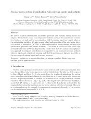
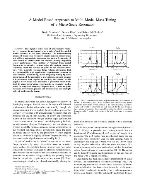
A <strong>Model</strong>-<strong>Based</strong> <strong>Approach</strong> <strong>to</strong> <strong>Multi</strong>-<strong>Modal</strong> <strong>Mass</strong> <strong>Tuning</strong><strong>of</strong> a <strong>Micro</strong>-Scale Resona<strong>to</strong>rDavid Schwartz ∗ , Dennis Kim † , and Robert M’Closkey ‡Mechanical and Aerospace Engineering DepartmentUniversity <strong>of</strong> California, Los AngelesAbstract— The signal-<strong>to</strong>-noise ratio <strong>of</strong> axisymmetric vibra<strong>to</strong>rygyroscopes is maximized when a pair <strong>of</strong> coriolis-coupledmodes resonate at the same frequency. The manufacturingprocess <strong>of</strong> micro-scale resona<strong>to</strong>rs creates random minute massand stiffness asymmetries that cause the natural frequencies <strong>of</strong>these modes <strong>to</strong> deviate from one another, thereby degradingsensor performance. One method <strong>of</strong> “tuning” these modalfrequencies <strong>to</strong> equality involves using electrostatic forces <strong>to</strong>selectively s<strong>of</strong>ten the stiffness at points in the resonant structure.This generally requires large volume electronics thatare incompatible with application requirements common <strong>to</strong>these sensors. Alternatively, modal frequency tuning by massperturbation <strong>of</strong> the resona<strong>to</strong>r is a promising approach becauseit is permanent and requires no ancillary electronics. In thispaper, a novel micro-scale resona<strong>to</strong>r is presented which lendsitself <strong>to</strong> mass perturbation experiments. A resona<strong>to</strong>r model,based on empirical frequency response data, is used <strong>to</strong> guidethe mass perturbation process and demonstrates how multiplepairs <strong>of</strong> modes can be tuned.I. INTRODUCTIONIn recent years there has been a resurgence <strong>of</strong> interest indeveloping compact inertial sensors for use in GPS-deniedenvironments. Before this can become a reality, though, advancementsmust first be made in the size and accuracy <strong>of</strong> thevibra<strong>to</strong>ry gyroscopes with axisymmetric resona<strong>to</strong>rs that areproposed for use in such systems. In theory, the symmetricnature <strong>of</strong> the resona<strong>to</strong>r design enables high performancecharacteristics due <strong>to</strong> the natural modal degeneracy intrinsic<strong>to</strong> axisymmetric designs. Unfortunately, the manufacturingprocess invariably produces random, minute asymmetries inthe resonant structure. These asymmetries cause the pairs<strong>of</strong> modes that are used by the gyroscope <strong>to</strong> sense angularmotion <strong>to</strong> resonate at slightly different frequencies which inturn reduces the signal-<strong>to</strong>-noise ration (Fig.1) [5].A pair <strong>of</strong> modes can be “tuned” <strong>to</strong> operate at the samefrequency either by using electrostatic forces or selectivemass loading. Electrostatic tuning involves applying staticvoltages <strong>to</strong> electrodes <strong>to</strong> change the effective modal stiffness.This process can be effective, but the electronics required <strong>to</strong>maintain the necessary voltage stability are generally largerthan the overall size requirements <strong>of</strong> the sensor [6]. Thus,mass tuning, in which a pair <strong>of</strong> modes is tuned by altering the* Email: daves@ucla.edu† Email: dongj@seas.ucla.edu‡ Corresponding author. Email: rtm@seas.ucla.edu. This work is supportedby DARPA contract P-1035-112802.G ain Magnitude (dB )G ain Magnitude (dB )3020100-10-2013.4 13.41 13.42 13.43F requency (kHz)3020100-10-2013.4 13.41 13.42 13.43F requency (kHz)S 3/D 3 S 3/D 4G ain Magnitude (dB )G ain Magnitude (dB )3020100-10-2013.44 13.4 13.41 13.42 13.43F requency (kHz)S 4/D 3 S 4/D 413.443020100-10-2013.4 13.41 13.42 13.43F requency (kHz)13.4413.44Fig. 1. The 2×2 empirical frequency response <strong>of</strong> the n=2 pair <strong>of</strong> modes <strong>of</strong>the UCLA Resona<strong>to</strong>r (URES). If the resona<strong>to</strong>r were fabricated with perfectsymmetry, these modes would resonate at the same frequency and only asingle peak would be observable in each channel. In the case presentedhere, minute asymmetries have caused the modes <strong>to</strong> exhibit a significantfrequency split. A similar split occurs in the n=3 modal pair as presentedFig. 7.mass distribution <strong>of</strong> the resona<strong>to</strong>r, appears <strong>to</strong> be a necessaryendeavor.On its face, mass tuning can be a straightforward process.Fig. 2 displays a potential mass tuning scenario for thefundamental Corilolis-coupled n=2 modes <strong>of</strong> simple ringgeometry. The n=2 modes have an elliptical shape and arethe ones most commonly used for rate sensing. With noasymmetry, the ring can vibrate with an n=2 mode shapeat any angular orientation with the same frequency. If amass asymmetry exists, two modes clearly define themselveswhose frequencies are no longer matched [1], [8]. The devicecan be tuned by placing additional mass on the anti-node <strong>of</strong>the mode with a higher frequency.<strong>Mass</strong> tuning has been successfully implemented on largerdevices. The Hemispherical Resona<strong>to</strong>r Gyroscope (HRG) [7],most notably used on the Hubble Space Telescope for instrumentstabilization, has been a benchmark for performance,though its 3 cm diameter is <strong>to</strong>o large for it <strong>to</strong> be considered amicro-scale device. The HRG is tuned by perturbing its mass
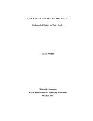
Lastly, one can calculate σ cos and σ sin using the frequencysplit and the location <strong>of</strong> the high frequency anti-nodes:25S 1/D 1D. <strong>Tuning</strong> Methodsσ cos = (ω n2−ω n1 )cos(2nΨ n2 )γ 2σ sin = (ω n2−ω n1 )sin(2nΨ n2 )γ 2.(13)A single modal frequency can be modified by finding acombination <strong>of</strong> perturbations <strong>of</strong> mass m p placed at locationsθ p that solveσ cosn(0) + ∑ Nmp=1 m p cos(2nθ p ) = 0σ sinn(0) + ∑ Nmp=1 m p sin(2nθ p ) = 0(14)where σ cosn(0) and σ sinn(0) are defined by the mass asymmetrystate before any perturbations are made. This set <strong>of</strong>equations can be solved with any number <strong>of</strong> perturbations.A single mass solution is attained with m 1 =γ 1 2√σcos 2 + σsin2and θ 1 = Ψ n2 . In other words, a specific quantity <strong>of</strong> mass isplaced precisely at the location <strong>of</strong> the anti-node <strong>of</strong> the highfrequency mode.If there are constraints on where the mass perturbationscan physically take place on the resona<strong>to</strong>r, as is the casewith the URES device, then two masses are required fortuning. There are multiple two mass solutions, and onesimple method for finding a solution is <strong>to</strong> pick two locations,denoted θ 1 and θ 2 , where the perturbations are <strong>to</strong> occur anduse[ ]m1=m 2[ ] −1 [ ]cos(2nθ1 ) cos(2nφ 2 ) σcosn(0)sin(2nφ 1 ) sin(2nθ 2 ) σ sinn(0)(15)<strong>to</strong> compute m 1 and m 2 . Generally, there are two constraintson the choices <strong>of</strong> θ 1 and θ 2 . First, they must be chosen sothat the inverted matrix is nonsingular, or, equivalentlymod (θ 1 − θ 2 , π 2n ) ≠ 0.Also, the solutions m 1 and m 2 must be positive (or negativein the case mass reduction). This is guaranteed ifθ 1 ≤ Ψ n2 ≤ θ 2 , 2nθ 2 − 2nθ 1 < π,which is interpreted as choosing θ 1 and θ 2 <strong>to</strong> be on eitherside <strong>of</strong> the high frequency anti-node. The closer the twoperturbation locations actually are <strong>to</strong> the higher frequencyanti-node, the smaller the amount <strong>of</strong> mass will be requiredfor tuning.It is also possible <strong>to</strong> extend this method <strong>to</strong> manipulatingthe frequencies <strong>of</strong> multiple modal pairs. In our case, we areinterested in tuning the n=2 and n=3 modes:σ cos2(0) + ∑ Nmp=1 m p cos(4θ p ) = 0σ cos2(0) + ∑ Nmp=1 m p sin(4θ p ) = 0σ cos3(0) + ∑ Nmp=1 m p cos(6θ p ) = 0σ cos3(0) + ∑ Nmp=1 m p cos(6θ p ) = 0(16)In general, this system <strong>of</strong> equations can be solved with twoor more masses [9].G ain Magnitude (dB )20151050-5-10-1523.56 23.565 23.57 23.575 23.58F requency (kHz)Fig. 6. Example <strong>of</strong> the model fitting algorithm. The red points display themeasured frequency response magnitude, while the trace is generated usingthe frequency domain model using 2×2 positive definite mass, stiffness anddamping matrices.A. Validation <strong>of</strong> <strong>Model</strong>sIV. EXPERIMENTAL RESULTSAn example <strong>of</strong> the model fit generated by using the methoddiscussed in Section III.A is shown in Fig. 6. Only themagnitude <strong>of</strong> the transfer function and its corresponding fitare shown. Still, the model for M,C,K, and R is a close fitfor both magnitude and phase in all four channels and ismore than 95% accurate as quantified by the H 2 norm <strong>of</strong> theresidual.The validation <strong>of</strong> the modelling process as well as estimates<strong>of</strong> γ 22 and γ 32 are done experimentally on a devicewith results shown in Table I. If a single mass perturbationis made <strong>to</strong> a measured system, the imbalance parametersσ cos(p) and σ sin(p) can be calculated usingσ cosn(p) = σ cosn(p−1) + γ n2 m p cos(2nθ p )σ sinn(p) = σ sinn(p−1) + γ n2 m p sin(2nθ p ).(17)In order <strong>to</strong> validate the model, data is taken before and aftera mass perturbation <strong>of</strong> known mass is made. The sensitivityγ n2 and an estimate <strong>of</strong> the location <strong>of</strong> the mass perturbationare then calculated using√¯γ n2 =m 1 (σcosn(p) p− σ cosn(p−1) ) 2 + (σ σsinn(p) −σ sinn(p−1) )( 2¯θ np =2n 1 σsinn(a))tan−1 −σ sinn(p−1)σ cosn(p) −σ cosn(p−1)(18)where the bar represents an estimate being made. Table Ishows that the sensitivity <strong>of</strong> the mass perturbation is actuallyextremely variable from test <strong>to</strong> test. This can be explainedby the large variability in the amount <strong>of</strong> mass being addedas a consequence <strong>of</strong> the physical process that is employed<strong>to</strong> deposit the mass. The perturbation model does accuratelyestimate the angle at which the mass was placed. This meansthat it also accurately estimates the location <strong>of</strong> the highfrequency mode and will be a useful aid in tuning.
Frequency<strong>Model</strong>ingDataset w 2 -w 1 Y 2 (degrees)(Hz)0 3.1 35.51 1.8 7.92 7.0 1.0TABLE IPERTURBATION MODEL VALIDATIONn=3 Data (Same device)Perturbation InformationPerturbation <strong>Model</strong>EstimatesPerturbation # # <strong>of</strong> masses location g 22 q 2p(degrees)(degrees)n=2 data1 1 -30 8.0 -30.522 - 67.5 4.7-67.8g 32 q 3pTABLE IIMASS TUNING EXAMPLEn=2 Data n=3 Data DepositionData Frequency Split Angle Estimate Frequency Split Angle Estimate Locationset (Hz) (degrees) (Hz) (Degrees) (Degrees)1 14.1 36.2 8.2 23.12 12.3 39.6 7.0 34.2 22.53 8.5 48.1 4.6 39.6 37.54 5.1 39.5 2.9 28.5 37.55 1.7 39.2 1.2 47.5 -37.5, 306 0.46 5.7 5.7 38.0 -30, 22.57 0.07 84.7 6.1 53.7 fine tuning w/ink0 6.5 31.21 12.2 222 2.8 201 1 -30 6.7 -30.32 2 -67.5 3.7 -67.420After coarse tuning (1.2 Hz split)10B efore tuning (8.2 Hz split)B. <strong>Tuning</strong> ExampleDue <strong>to</strong> the lack <strong>of</strong> a consistent mass quantum that canbe placed on the resona<strong>to</strong>r, tuning a modal pair <strong>to</strong> degeneracyis difficult. Despite this challenge, in this sectionwe successfully demonstrate the model driven approach <strong>to</strong>tuning, starting with an unperturbed URES resona<strong>to</strong>r. Thefollowing example uses several different tuning strategies atdifferent stages <strong>to</strong> reach a final, modally tuned, state. Atfirst, masses are placed with the goal <strong>of</strong> tuning both modes.As this becomes more difficult the strategy is shifted <strong>to</strong>wardachieving a tuned state for one mode.The experimental results are displayed in Table II. Eachrow <strong>of</strong> table gives the modeled parameters <strong>of</strong> the n = 2 andn = 3 models, and the location(s) <strong>of</strong> the perturbation(s) madebefore the data was taken. In the first stage, masses are placedin order <strong>to</strong> reduce the split in the n = 3 mode as much aspossible without reducing the split <strong>of</strong> the n = 2 modes. Sincethe mass <strong>of</strong> each perturbation is so variable, the perturbationsare made one at a time for the first 3 perturbations. Thesplits <strong>of</strong> both modes reduce each time, again confirmingthat the model based predictions are useful. After the fourthperturbation, the split is 1.2 Hz for the n = 3 modes and 1.7Hz for the n = 2 modes. At this point (Dataset 5), the goldball mass perturbation is <strong>to</strong>o large <strong>to</strong> reduce either split withonly one mass, i.e. a single gold ball will cause “overshoot”<strong>of</strong> the desired frequencies, so any subsequent perturbationswill only address reducing the n = 2 modal split and forthis case, a two-location solution is found that reduces thesplit <strong>of</strong> the n = 2 modes <strong>to</strong> 0.46 Hz (Dataset 6). AfterDataset 6, further reduction in the n = 2 modal frequencysplit is not possible with gold ball mass perturbations soa different mechanism employing silver ink deposition isused <strong>to</strong> accomplish fine tuning. The mass quantum associatedwith the ink is several orders <strong>of</strong> magnitude smaller than thegold balls. This process <strong>to</strong>ok several iterations which havebeen removed for brevity but the resona<strong>to</strong>r’s n = 2 modeswere tuned <strong>to</strong> less than a 0.1 Hz split (see Fig. 8) after theconclusion <strong>of</strong> the ink deposition (Dataset 7).G ain Magnitude (dB )G ain Magnitude (dB )3020100-100-10-20S 1/D 1S 2/D 2-3023.03 23.035 23.04 23.045 23.05F requency (kHz)Fig. 7.Before and after tuning <strong>of</strong> the n = 3 modesAfter fine tuning (
V. CONCLUSIONA model based approach has been developed and used<strong>to</strong> guide the mass loading <strong>of</strong> a micro-resona<strong>to</strong>r with theobjective <strong>of</strong> reducing the modal frequency split between twonominally degenerate modes. Of particular interest are then = 2 and n = 3 modal pairs since these are the modesthat can be exploited for angular rotation rate sensing inaxisymmetric vibra<strong>to</strong>ry gyros. The algorithm only requiresknowledge <strong>of</strong> the mode shapes in order <strong>to</strong> estimate thelocation <strong>of</strong> the anti-nodes from models fit <strong>to</strong> empiricalfrequency response data. The biggest challenge in this studywas not performing the measurements or implementing thealgorithm, but rather the process for effecting the mass perturbationis not sufficiently developed <strong>to</strong> produce a consistentmass “quanta” across all experiments. This is especiallytrue <strong>of</strong> the gold ball deposition which had the advantage<strong>of</strong> creating a large change in the modal properties <strong>of</strong> theresona<strong>to</strong>r. Ultimately, a hybrid approach was used in whichsilver ink deposition was employed <strong>to</strong> further reduce themodal frequency split. The impact <strong>of</strong> mass perturbation onthe modal quality fac<strong>to</strong>rs is also <strong>of</strong> interest since higherquality fac<strong>to</strong>rs produce higher signal-<strong>to</strong>-noise ratios in tunedvibra<strong>to</strong>ry gyros. Fortunately, the current data suggest that thequality fac<strong>to</strong>rs are not changed by these mass perturbations.REFERENCES[1] Allaei, D., Soedel, W., and Yang, T.Y., “Natural frequencies <strong>of</strong> ringsthat depart from perfect axial symmetry.” Journal <strong>of</strong> Sound andVibration, Vol. 111, pp. 9-27, 1986.[2] Charnley, T., and Perrin, R., “Perturbation studies with a thin circularring.” Acustica, Vol. 28, pp. 140-146, 1973.[3] Fell, C.P., “Method for matching vibration mode frequencies on avibrating structure” US Pat. 5739410, 1996.[4] Gallacher, B. J., “<strong>Multi</strong>-modal tuning <strong>of</strong> a ring gyroscope using laserablation” Proc. Inst. Mech. Eng. C.,Vol. 217, pp. 557-76, 2000.[5] Kim, D., and M’Closkey, R. T., “Dissecting tuned MEMS vibra<strong>to</strong>rygyros,” book chapter in Feedback Control <strong>of</strong> MEMS <strong>to</strong> A<strong>to</strong>ms. Gorman,Jason J.; Shapiro, Benjamin (ed.), Oc<strong>to</strong>ber 2011, Springer.[6] Kim, D-J., and M’Closkey, R.T., “A systematic method for tuningthe dynamics <strong>of</strong> electrostatically actuated vibra<strong>to</strong>ry gyros,”IEEE Trans. Control System Technology, Vol. 14, No. 1, pp. 69–81,2006.[7] Lynch, D.D. “Coriolis Vibra<strong>to</strong>ry Gyros,” Symposium Gyro Technology,Stuttgart Germany, September 1998.[8] Rourke, A.K., McWilliam S., and Fox, C.H.J. , “<strong>Multi</strong>-mode trimming<strong>of</strong> imperfect rings,” Journal <strong>of</strong> Sound and Vibration, Vol. 248, No. 4,pp. 695724, 2001[9] Schwartz, D., “<strong>Mass</strong> Perturbation Techniques for <strong>Tuning</strong> and Decoupling<strong>of</strong> a Disk Resona<strong>to</strong>r Gyroscope.” PhD thesis. University <strong>of</strong>California, Los Angeles, 2010.[10] Schwartz, D., Kim, D.J., and M’Closkey, R.T., “Frequency <strong>Tuning</strong> <strong>of</strong> aDisk Resona<strong>to</strong>r Gyro Via <strong>Mass</strong> Matrix Perturbation”, ASME Journal<strong>of</strong> Dynamic Systems, Measurement, and Controls, Vol. 131, No. 6,p. 061004 , 2009.[11] Zhbanov, Yu. K., and Zhuravlev, V. F., “On the Balancing <strong>of</strong> aHemispherical Resona<strong>to</strong>r Gyro,” Mech. Solids, Vol. 33, No. 4, pp. 2–13, 1998.