Pro-Series II Manual - Schnitz Racing
Pro-Series II Manual - Schnitz Racing
Pro-Series II Manual - Schnitz Racing
- No tags were found...

You also want an ePaper? Increase the reach of your titles
YUMPU automatically turns print PDFs into web optimized ePapers that Google loves.
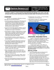
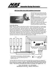
SCHNITZ MOTORSPORTSDSC-PRO2, PRO SERIES <strong>II</strong> IGNITIONCOIL 1,4 (OPTIONAL)16GA YELLOW, PAGE 22COIL 1,4 NEGATIVE16GA WHITE, PAGE 22FUEL SOLENOID (GROUND)RECOMMEND 16GA , PAGE 24NOS SOLENOID (GROUND)16GA ORANGE, PAGE 24ACTIVATION INPUT20GA ORANGE, PAGE 24CLUTCH SWITCH INPUT (2-STEP)20GA YELLOW, PAGE 24KILL INPUT20GA GRAY, PAGE 25SHIFT LIGHT GROUND20GA BROWN, PAGE 25SHIFT SOLENOID GROUND20GA GREEN, PAGE 251011121314151617USER MANUALANDINSTALLATION GUIDESCHNITZMOTORSPORTSRUNOR VOLTSHIGHRPMLAUNCHRPMPRO SERIES <strong>II</strong>DIAGNOSTICSENGINE RPMSHIFT RPMNOS DELAY TIMEIN SECONDSTRANSMISSIONTYPE &NOS START PERCENTSHIFT COUNTERNOS FINAL PERCENTENGINE KILL TIMENOS BUILD TIMETIMING ADVANCE RPMIN SECONDSRETARD BUILD TIMEIGNITION TIMING IN SECONDSRETARD & ADVANCEPROGRAMDSC-PRO201 23456781 9NOS 100% POWER DELAYTIME IN SECONDS01 2345678.1 901 2345678.01 9ELECTRONICIGNITIONCONTROLLERDSC-PRO201 2345678.001 918 19 COIL 2,3 (OPTIONAL)16GA PURPLE, PAGE 22COPYRIGHT (C) 2000 BY, SCHNITZ MOTORSPORTS, ALL RIGHTS RESERVED8765432COIL 2,3 NEGATIVE16GA BLUE, PAGE 22GROUND, 14GA BLACK, PAGE 22TRIGGER (GROUND), 20GA BLACKANALOG DATA OUTPUTPAGE 26TRIGGER +12V20GA RED, PAGE 22+12 VOLTS SWITCHED16GA RED, PAGE 22TACH OUTPUTPAGE 26TRIGGER 2,320GA BLUE, PAGE 22TRIGGER 1,420GA WHITE, PAGE 22Preliminary
IMPORTANTStock Crankshaft Trigger will NOT work with this Controller.Use only DYNA PRO SERIES ® Trigger.Use only a Dual Magnet Rotor for Crankshaft Trigger.Use only .7ohm High Energy Ignition Coils. Part #DC9-1, DC9-2Use only Static Suppression Spark-plug Wires. Part #DW-800All items listed above are available from <strong>Schnitz</strong> <strong>Racing</strong>. 1-219-728-9730Notice of CopyrightCopyright (C) 2000 <strong>Schnitz</strong> Motorsports, Decatur, Indiana. All rights reserved.Copyright law protects this document. It is unlawful to make copies, modify, ordistribute without written consent from <strong>Schnitz</strong> Motorsports. It is the responsibility ofthe purchaser to follow all guidelines and safety procedures supplied with this productand any other manufactures product used with this product. It is also the responsibilityof the purchaser to determine compatibility of this device with the vehicle and othercomponents.<strong>Schnitz</strong> Motorsports assumes no responsibility for damages resulting fromaccident, improper installation, misuse, abuse, improper operation, lack of reasonablecare, or all previously stated reasons due to incompatibility with other manufacturer'sproducts.<strong>Schnitz</strong> Motorsports assumes no responsibility or liability for damages incurredfrom the use of products manufactured or sold by <strong>Schnitz</strong> Motorsports on vehicles usedfor competition racing.<strong>Schnitz</strong> Motorsports neither recommends nor approves the use of productsmanufactured or sold by <strong>Schnitz</strong> Motorsports on vehicles which may be driven onpublic highways or roads, and assumes no responsibility for damages incurred fromsuch use.It is the purchaser’s responsibility to check the state and local laws pertaining tothe use of Nitrous Oxide for racing applications. <strong>Schnitz</strong> Motorsports does notrecommend nor condone the use of its products for illegal street racing.CautionFollow all recommended safety guidelines from this and other manufacturerinstallation guidelines. Never install any device, which pulsates nitrous solenoidswithout a safety solenoid installed. Static suppression ignition wires must be usedwith this unit! Mount the Ignition Controller as far away from secondary ignitioncomponents (ignition coils, ignition wires, etc.) As is physically possible.Installation of <strong>Schnitz</strong> Motorsports products signifies that you haveread this document and agree to the terms stated within.Page 2
<strong>Pro</strong> <strong>Series</strong> <strong>II</strong>OverviewDescription:The <strong>Pro</strong> <strong>Series</strong> <strong>II</strong> Ignition Controller is a highly integrated Digital Ignition System withinnovative features that enable today’s racing technology to be utilized to its maximum potential.The system was designed to be simple while maintaining focus on features. This design techniquehas led to a controller that can be installed in hours not days, provided other operational systemshave already been installed or are existing on the motorcycle.Features:A - Ignition System1 - The controller uses digital circuitry to precisely monitor and control the Inductive Type ignitiondrivers. This design enables precise and consistent ignition timing control from High EnergyIgnition Coils. The High-Energy design ensures ignition performance for today’s technology.2 – Ignition Timing Control is integrated into the controller. A Timing Advance Feature has beenadded, This Feature can be turned on or off. The amount of Timing Advance as well as AdvanceRPM Range is fully adjustable. The Ignition Timing can be controlled either direction of StaticTiming. You may Retard the Timing more than you advance it. There are three stages and types oftiming retard available. The first stage or Initial Retard can range from 0 to 12 degrees. This stage isactivated immediately when the <strong>Pro</strong>gressive Nitrous Timer System is activated. The second stagewas designed with a progressive timer that applies timing control over a period of time. This stageis activated when the Nitrous Delay Timer times out. The second stage of retard can range from 0to 22 degrees and the <strong>Pro</strong>gressive Retard Timer can be programmed from .200 to 9.900 seconds.The third type of Timing Retard is a Start Retard function. The Start Retard can be set from 0 to 15degrees of Ignition Retard and is Only Active during Initial Engine Startup. This allows highcompression engines to start easily and the Timing can be set to a point that will allow the engineto idle correctly.IMPORTANT – The first and second stages of retard are added together when usedtogether. Example: 1 st stage at 4 degrees and 2 nd stage at 12 degrees would provide a totalof 16 degrees of timing retard.B – Features based on Engine RPM Control1 – High RPM, This selection enables the user to program an Upper RPM Limit for the engine.Valid RPM Range is from 3,000 to 16,000 RPM in 100-RPM Increments.2 – Launch RPM, This selection enables the user to program the RPM at which the engine and/ormotorcycle leave starting line with. Applying +12V signal activates this stage of RPM control.Valid RPM Range is from 3,000 to 16,000 RPM in 100-RPM Increments.3 – Sequential Shift RPM, This selection enables the user to program the RPM at which the ShiftLight Output becomes active and/or Auto Shifting can occur. A different RPM can <strong>Pro</strong>grammedfor each gear, this is Sequential Shifting. The controller sequences through the User <strong>Pro</strong>grammedShift Points. Shift Sequencing begins when the Activation terminal is ON. The Shift Light Output isON any time engine RPM is above the Shift RPM Setting, and OFF whenever engine RPM fallsbelow the Shift RPM. The Auto-Shift System is very flexible and can be configured for all populartransmission styles. There is a 1-second delay timer built in for the 1-2 shift, this helps to controlshort shifts due to wheel spin off the line. A built-in and adjustable shift counter keeps track ofgear position and engine kill requirements. The shift counter also stops false shifting in top gearposition. The shift system can programmed for automatic or manual shifting. The rider can do amanual or Shift Override at any time, even while in auto mode. The shift counter is updatedinternally when manual shifts occur also.Note - The Auto-Shift Function will NOT work with Air over Air Systems asRequired for All <strong>Pro</strong> Classes.Page 3
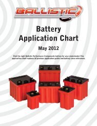
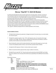
1.0 - The Basics of Setting Controller ParametersSCHNITZMOTORSPORTSRUNOR VOLTSHIGHRPMLAUNCHRPMSHIFT RPMTRANSMISSIONTYPE &SHIFT COUNTERENGINE KILL TIMETIMING ADVANCE RPMIGNITION TIMINGRETARD & ADVANCEDIAGNOSTICS1 - Select SwitchPRO SERIES <strong>II</strong>ENGINE RPMNOS 100% POWER DELAYTIME IN SECONDSNOS DELAY TIMEIN SECONDSNOS START PERCENTNOS FINAL PERCENTNOS BUILD TIMEIN SECONDSRETARD BUILD TIME INSECONDSELECTRONICIGNITIONCONTROLLERPROGRAMDSC-PRO2TIMER DURATION0 1 2 3456781 90 1 2 345678.1 9DSC-PRO20 1 2 345678.01 9.0010 1 2 345679 82 - <strong>Pro</strong>gramming Switch 3 - Data SwitchesSwitch Descriptions and Functions1 - Switch #1 is the FUNCTION SELECT SWITCH, This switch is usedto select which parameter is displayed and also selects thatparameter for programming.2 - Switch #2 is the PROGRAM SWITCH, When this switch is presseddown and held for 2-seconds the DATA switches will be read andthe settings will be programmed into the controller. If anINVALID setting is read the controller will NOT save the setting andwill display an INVALID message on the display.3 - Data Switches #3 are for entering RPM Data, Ignition Retard Data,NOS Control Data, and for selecting various options as describedin the following pages.Example <strong>Pro</strong>gramming SequenceFunction Select Switch(#1) set to HIGH RPM (Switch pointing to HIGH RPM)Data Switch 1 set at 1, .01 at 2, .001 at 5, .001 at 0Data Switch 1 x 10,000 RPMData Switch .1 x 1,000 RPMData Switch .01 x 100 RPMData Switch .001 is IgnoredPressing and holding PROGRAM Switch for 2-seconds will set the HIGH RPMat 12,500 RPM.Please refer to each of the following sections for setting all Functions.Page 6
1.4 – Setting SHIFT RPM, SHIFT STYLE & SHIFT COUNTERNOTE All Shift RPM’s MUST BE +/- 1,000 RPM of 1 st Shift RPM!Set SELECT Switch to the SHIFT RPM this is the 1 st Shift RPMWhen a NEW 1 st Shift RPM is <strong>Pro</strong>grammed all Shift RPM’s will be set to the 1 st Shift RPM SettingAutomatically.Example that would set SHIFT RPM at 9,8001 set at 0.1 set at 9.01 set at 8.001 set at 0Press PROGRAM Button until the display reads PROGRAM. Release the button and the display will now read9,800. SHIFT LIGHT RPM is now set at 9,800 RPM. NOTE, IF the 1 st Shift RPM is <strong>Pro</strong>grammed it will take acouple of Seconds to Update the Following Shift RPM’s. Valid RPM range 3,000 to 16,000 RPM in 100-RPMIncrements.NOTE: Only the 1 st SHIFT RPM will be used until the ACTIVATION Terminal is Activated.. This is done witha +12 volt signal. Please refer the next section for more information on the Auto-Shift System and its use.NOTE: Additional Shift RPM’s are set as follows.Set the SELECT Switch to SHIFT STYLE & SHIFT COUNTER Use the .001 DATA Switch to Select the DesiredShift RPM to Set. You must turn the .001 DATA Switch to #2 to #5 positions to access the Sequential Shift RPMSettings. The Display will show the which Shift Point you have selected. After Selecting the Desired Shift RPM,It can be <strong>Pro</strong>grammed by using the Additional DATA Switches as outlined above.The Auto-Shift is NOT activated until the Activation terminal is armed. Applying +12 volts to the terminaldoes this. At this time of activation a 1-second timer will begin, NO AUTO SHIFTS will occur until this 1-second timer is done. This prevents sudden shifts due to wheel spin at the initial launch. A shift override maybe activated at any time by applying +12V to the SHIFT Terminal. This is done with a shift button. A shiftoverride will be counted by the AUTO-SHIFT shift counter. Ignition KILL for the shifts are controlledautomatically by the controller. To use the SHIFT COUNTER with <strong>Manual</strong> shifting set the SHIFT STYLE asoutline below. Auto Shift must be ACTIVATED for SHIFT COUNTER to work even when using MANUALSHIFT Modes.SHIFT STYLE options are as follows:LITENo AUTO SHIFTING. Engine kill for all shifts. <strong>Manual</strong> Shift Only.1-2 LITE No AUTO SHIFTING. Will NOT kill for 1-2 shift. <strong>Manual</strong> Shift Only.1-2-3 LITE No AUTO SHIFTING. Will NOT kill for 1-2, 2-3 shifts. <strong>Manual</strong> Shift Only.AUTOLITE No AUTO SHIFTING. Will NOT kill for all shifts. <strong>Manual</strong> Shift Only.STANDARD AUTO SHIFT ON. Will kill for all gears.1-2 AUTO AUTO SHIFT ON. Will NOT kill ignition for 1-2 shift.1-2-3 AUTO AUTO SHIFT ON. Will NOT kill ignition for 1-2-3 shifts.FUL AUTO AUTO SHIFT ON. Will NOT kill ignition for all shifts.To change the SHIFT STYLE setting set the SELECT Switch to SHIFT STYLE & SHIFT COUNTER. Set the .001DATA switch to 0. Pressing the PROGRAM button at this time will select the next option available. All optionmay be viewed by pressing the PROGRAM button repeatedly.SHIFT COUNTER options are as follows:2-SPEED No Auto-Shifts after 1 to 2 shift.3-SPEED No Auto-Shifts after 2 to 3 shift.4-SPEED No Auto-Shifts after 3 to 4 shift.5-SPEED No Auto-Shifts after 4 to 5 shift.6-SPEED No Auto-Shifts after 5 to 6 shift.To change the SHIFT COUNTER setting set the SELECT Switch to SHIFT STYLE & SHIFT COUNTER. Set the.001 DATA switch to 1. Pressing the PROGRAM button at this time will select the next option available. Alloptions may be viewed by pressing the PROGRAM button repeatedly.Page 8
1.5 – Setting IGNITION TIMING, RETARD and ADVANCENote - Initial RETARD and Build RETARD Settings are Added together for Amount of TotalIgnition Timing RETARD.Setting INITIAL RETARDSet SELECT Switch to IGNITION TIMING, RETARD and ADVANCENote - #1 Data Switch must be at 0Example that would set INITIAL RETARD to 6 degrees1 set at 0 - Used to select Timing Option.1 set at 0 (not used).01 set at 0.001 set at 6Press PROGRAM button until the display reads PROGRAM. Display will now read INIT 6 andINITIAL RETARD is set to 6 degrees. Valid range 1 to 12 Degrees, 1Degree Increments. Setting to 0will turn this function/ OFF. NOTE: This retard stage will turn on immediately when the NOSActivation is turned on. (+12volts applied). The ignition retard will remain active until the NOSsystem resets.Setting Ignition Timing BUILD RETARD, 2 nd Stage of RetardSet SELECT Switch to IGNITION TIMING, RETARD and ADVANCENote - #1 Data Switch must be set at 1Example that would set BUILD RETARD to 14 degrees1 set at 1 - Used to select Timing Option.1 set at 0 (not used).01 set at 1.001 set at 4Press PROGRAM button until the display reads PROGRAM. Display will now read BUILD 14 andBUILD RETARD is set to 14 degrees. Valid range 1 to 22 Degrees, 1 Degree Increments. Setting to 0will turn this function OFF.NOTE: This retard stage will turn on when the NOS Delay Timer has timed out and the NOSSolenoids have been turned on. The retard will progressively come on based on the RETARDBUILD TIME setting.Viewing TOTAL Amount of Ignition RetardSet SELECT Switch to IGNITION TIMING, RETARD and ADVANCENote - #1 Data Switch must be set at 2At this time the Display will show the Total amount of Ignition Timing Retard that will be appliedwhen the NOS System is Activated.Setting START RETARDSet SELECT Switch to IGNITION TIMING, RETARD and ADVANCENote - #1 Data Switch must be at 4Example that would set START RETARD to 12 degrees1 set at 0 - Used to select Timing Option.1 set at 0 (not used).01 set at 1.001 set at 2Press PROGRAM button until the display reads PROGRAM. Display will now read S RET: 12 andSTART RETARD is set to 12 degrees. Valid range 0 to 15 Degrees, 1Degree Increments. Setting to 0will turn this function OFF. NOTE: This retard stage is only Active During Engine Starting.Page 9
Setting Ignition Timing Degrees of ADVANCENOTE - This Setting Does NOT have to be used(Set to 0). The Controller can adjust the Timingeither direction(retard or advance) of Static Timing. Please Refer to Next Section regarding TimingAdvance RPM Control.Set SELECT Switch to IGNITION TIMINGNote - #1 Data Switch must be set at 3Example that would set ADVANCE to 10 degrees1 set at 3 - Used to select Timing Option.1 set at 0 (not used).01 set at 1.001 set at 0Press PROGRAM button until the display reads PROGRAM. Display will now read ADV 10 andTiming ADVANCE is set to 10 degrees. Valid range 0 to 34 Degrees, 1 Degree Increments. Settingto 0 will turn this function OFF.Note - The Degrees of Advance will be Added to the Static Timing of the Engine. Example - Ifthe Static Timing is at 25 and Timing Advance Set at 10 the Total Ignition Timing Advancewould be 35 Degrees. The RPM at which the Timing Advance works is Fully <strong>Pro</strong>grammableand is Explained in the Next Section.1.6 – Setting Ignition TIMING ADVANCE RPM (Advance Curve)Note - These Settings along with Degrees of Timing Advance will Determine the IgnitionTiming Advance Curve.Setting IGNITION TIMING BEGINNING ADVANCE RPMSet SELECT Switch to TIMING ADVANCE RPMNote - #.001 Data Switch must be set at 0IMPORTANT - The Beginning Advance RPM MUST be at Least 1,000 RPM Lower than the FullTiming Advance RPM. It may be necessary to Set the Full Timing Advance RPM First so theTiming Advance Beginning RPM can be set to the Desired Value.Example that would set TIMING ADVANCE Beginning RPM at 1,800 rpm1 set at 0.1 set at 1.01 set at 8.001 set at 0 - Used to Select Beginning and Full Timing Advance RPMPress PROGRAM button until the display reads PROGRAM. Display will now read 1,800 andTIMING ADVANCE Beginning RPM is set at 1,800 RPM. Valid RPM range 1,600 to 15,000 RPM in100-RPM Increments.Setting FULL TIMING ADVANCE RPMSet SELECT Switch to TIMING ADVANCE RPMNote - #.001 Data Switch must be set at 1IMPORTANT - This setting will determine the RPM at which Full Timing Advance is Reached.Example that would set FULL TIMING ADVANCE RPM at 4,800 rpm1 set at 0.1 set at 4.01 set at 8.001 set at 0 - Used to Select Beginning and Full Timing Advance RPMPress PROGRAM button until the display reads PROGRAM. Display will now read 4,800and FULL TIMING ADVANCE RPM is set at 4,800 RPM. Valid RPM range 2,600 to 16,000 RPMin 100-RPM Increments.Page 10
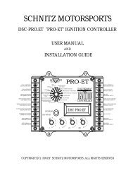
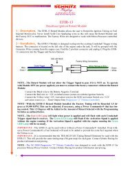
IMPORTANT INFORMATION: This setting is used along with DEGREES OF TIMINGADVANCE to adjust the Advance Curve for the ignition timing. The following informationcan be used to build almost any desired timing curve.CAUTION: Setting the Advance to High can Cause DETONATION which WILL HARM theengine. If you do not know where to set the ignition timing and advance setting then contactYOUR engine builder to obtain basic ignition timing information.Formula to Determine Advance Curve:Advance RPM Range = Full Timing Advance RPM - Timing Advance Beginning RPMRPM for 1 Degree of Advance = Advance RPM Range / Degrees of Timing AdvanceDegrees of Advance Per 1,000 RPM = 1000 / RPM for 1 DegreeExample: ADVANCE BEGINING RPM = 1,800 rpmFULL TIMING ADVANCE RPM = 4,800 rpmDEGREES OF TIMING ADVANCE = 16 degreesStatic Engine Timing = 20 degreesTotal Timing Advance = 36 degrees4,800 - 1,800 = 3,000 (Advance RPM Range)3,000 / 16 = 187.5 (Every 187.5 RPM Increase will Advance Timing 1 Degree)1000 / 187.5 = 5.35 (Ignition Timing will Advance 5.35 Degrees every 1,000 RPM)Graph of Example Ignition Timing CurveDEGREES OF ADVANCE4035302520151051,000 2,000 3,000 4,000 5,000 6,000 7,000 8,000 9,000 10,000ENGINE RPM1.7 - Setting RETARD BUILD TIMESet SELECT Switch to RETARD BUILD TIME IN SECONDSExample that would set RETARD BUILD TIME at 2.400 seconds1 set at 2.1 set at 4.01 set at 0 (not used).001 set at 0 (not used)Press PROGRAM button until the display reads PROGRAM. Display will now read 2.400 andRETARD BUILD TIME is set at 2.400 seconds. Valid Time Range .200 to 9.900 seconds, .1 secondIncrements.Note: This setting determines the Ramp of IGNITION TIMING RETARD. A low setting i.e. (.200)will make the TIMING RETARD very aggressive. A high setting i.e. (9.900) will make the TIMINGRETARD gradual.Page 11
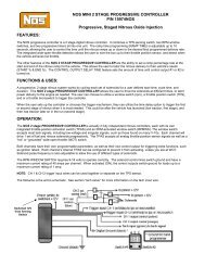
1.8 - Setting NOS 100% POWER DELAY TIMESet SELECT Switch to NOS 100% POWER DELAY TIME IN SECONDSExample that would set NOS 100% POWER DELAY at 4.000 seconds1 set at.1 set at 0.01 set at 0.001 set at 0Press PROGRAM button until the display reads PROGRAM. Display will now read 4.000 and NOS100% POWER DELAY is set to 4.000 seconds. Valid range 0.000 to 9.999 seconds in .001 secondincrements. Setting this to 0.000 turns off the NOS 100% POWER Function OFF.Example NOS Setups using <strong>Pro</strong>gressive and 100% Power TimersExample 1PERCENT OF NITROUS100908070605040302010NOS DELAYNOS 100%POWERNOS PROGRESSIVERAMP0.000 1.000 2.000 3.000 4.000 5.000 6.000 7.000 8.000 9.000TIME IN SECONDSNOS DELAY TIME = 0.500NOS FINAL% #1 = 80%NOS FINAL% #2 = OFF (0%)NOS BUILD TIME #1 = 8.000NOS BUILD TIME #2 = OFF (0.000)NOS 100% POWER DELAY = 5.000Example 2PERCENT OF NITROUS100908070605040302010NOS DELAYNOS RAMP1NOS RAMP20.000 1.000 2.000 3.000 4.000 5.000 6.000 7.000 8.000 9.000TIME IN SECONDSNOS DELAY TIME = 1.000NOS START% = 10%NOS FINAL% #1 = 30%NOS FINAL% #2 = 100%NOS BUILD TIME #1 = 4.000NOS BUILD TIME #2 = 2.000NOS 100% POWER DELAY = 0.000(OFF)Page 12
1.9 – Setting NOS DELAY TIMERSet SELECT Switch to NOS DELAY TIME IN SECONDSExample that would set NOS DELAY TIME at 1.250 seconds1 set at 1.1 set at 2.01 set at 5.001 set at 0Press PROGRAM button until the display reads PROGRAM. Display will now read 1.250 and NOSDELAY TIME is set to 1.250 seconds.Valid range 0.000 to 9.999 seconds in .001 second increments.Note: This is timer to delay the start of NOS. A time of 0.000 will allow the NOS to startimmediately when activated. Also the Ignition Timing BUILD Retard will NOT begin until thisDelay Timer has timed out.1.10 – Setting the NOS START PERCENTSet SELECT Switch to NOS START PERCENTExample that would set NOS START PERCENT at 34%1 set at 0 (not used).1 set at 0.01 set at 3.001 set at 4Press PROGRAM button until the display reads PROGRAM. Display will now read 34% and NOSSTART PERCENT is set at 34%. Valid Percentage Range 10 to 100% in 1% increments. Setting to 0%will turn NOS OFF even if NOS is Activated.Note: This setting allows the starting POWER developed from the NOS to be controlled fortraction and other reasons.1.11 – Setting NOS FINAL PERCENT #1Set SELECT Switch to NOS FINAL PERCENTExample that would set NOS FINAL PERCENT #1 at 60%1 set at 0 - Used to Select Final% #1 or Final% #21 set at 0.01 set at 6.001 set at 0Press PROGRAM button until the display reads PROGRAM. Display will now read 60% and NOSFINAL PERCENT #1 is set at 60%. Valid Percentage Range 10 to 100%, 1% Increments. Setting to0% will turn NOS OFF even if NOS is Activated.1.12 – Setting NOS FINAL PERCENT #2Set SELECT Switch to NOS FINAL PERCENTExample that would set NOS FINAL PERCENT #2 at 100%1 set at 1 - Used to Select Final% #1 or Final% #21 set at 1.01 set at 0.001 set at 0Press PROGRAM button until the display reads PROGRAM. Display will now read 100% and NOSFINAL PERCENT #1 is set at 100%. Valid Percentage Range 10 to 100%, 1% Increments. SettingFinal% #2 to 0% will Disable the 2 nd Nitrous Ramp.Page 13
1.13– Setting NOS BUILD TIME #1Set SELECT Switch to NOS BUILD TIME IN SECONDSNote: .001 Data Switch MUST be set at 0 to Set this Function.Example that would set NOS BUILD TIME #1 at 3.500 seconds1 set at 3.1 set at 5.01 set at 0 (not used).001 set at 0 - Not used for Time SettingPress PROGRAM button until the display reads PROGRAM. Display will now read 3.500 and NOSBUILD TIME #1 is set at 3.500 seconds. Valid Time Range .200 to 9.900 seconds in .1 secondIncrements.Note: This setting determines how fast the NOS goes from START PERCENT to FINALPERCENT #1. A shorter BUILD TIME will make the NOS Power Curve more Aggressive.1.14– Setting NOS BUILD TIME #2Set SELECT Switch to NOS BUILD TIME IN SECONDSNote: .001 Data Switch MUST be set at 1 to Set this Function.Example that would set NOS BUILD TIME #2 at 2.000 seconds1 set at 2.1 set at 0.01 set at 0 (not used).001 set at 1 - Not used for Time SettingPress PROGRAM button until the display reads PROGRAM. Display will now read 2.000 and NOSBUILD TIME #2 is set at 2.000 seconds. Valid Time Range .200 to 9.900 seconds in .1 secondIncrements. Setting this Function to 0.000 will Turn OFF the 2 nd Nitrous <strong>Pro</strong>gressive Ramp.Note: This setting determines how fast the NOS goes from FINAL PERCENT #1 to FINALPERCENT #2. A shorter BUILD TIME will make the NOS Power Curve more Aggressive.1.15 – Setting NOS MINIMUM ACTIVATION RPMSet SELECT Switch to NOS BUILD TIME IN SECONDSNote: .001 Data Switch MUST be set at 2 to Set this Function.Example that would set NOS MINIMUM ACTVATION RPM at 7,2001 set at 0.1 set at 7.01 set at 2.001 set at 2 - Not used for RPM SettingPress PROGRAM Button until the display reads PROGRAM. Release the button and the displaywill now read 7,200. NOS will now be Disabled when RPM is below 7,200.Valid RPM range 3,000to 16,000 RPM in 100-RPM Increments.Page 14
1.16 – Setting NOS MAXIMUM ACTIVATION RPMSet SELECT Switch to NOS BUILD TIME IN SECONDSNote: .001 Data Switch MUST be set at 3 to Set this Function.Example that would set NOS MAXIMUM ACTVATION RPM at 11,2001 set at 1.1 set at 1.01 set at 2.001 set at 3 - Not used for RPM SettingPress PROGRAM Button until the display reads PROGRAM. Release the button and the displaywill now read 11,200. NOS will now be Disabled when RPM is over 11,200.Valid RPM range 3,000to 16,000 RPM in 100-RPM Increments.Note: This Setting should be set to RPM that is Lower than the High RPM Setting. This will allowthe NOS to turn OFF before the Engine Rev Limiter is active.1.17 – Setting NOS SHIFT COUNTERSet SELECT Switch to NOS BUILD TIME IN SECONDSNote: .001 Data Switch MUST be set at 4 to Set this Function.The Display will read the Current NOS SHIFT COUNTER position. If the Display Reads OFF theNOS SHIFT COUNTER Function is Disabled and will NOT have any effect on the NOS System. Ifthe Display Indicates a Gear Position then the NOS Timers will NOT begin Until the Shift CounterHas Reached the Selected Gear.To Turn OFF or Select the Desired Gear Position Press the PROGRAM Button until the displayreads PROGRAM. Release the button and the NOS SHIFT COUNTER will Increment to the nextOption.Note: The NOS SHIFT COUNTER must NOT be Set to a Higher Gear Position then the ShiftCounter for the Sequential Shift Light Function or the NOS Timers will NOT become Active.1.18 – Checking Battery VoltageSet SELECT Switch to RUN and/or VOLTS and Press the PROGRAM ButtonBattery Voltage will now be displayed. It is normal for the battery voltage reading to vary with theengine running. This is due to the short duration high current demands of the ignition coils.Page 15
Section 2, Diagnostics2.0 – Description of Diagnostic FunctionsThe Diagnostics Functions will allow the user to test the output of the ignition coils, static time theignition system, and test the activation inputs. These functions are only available if NO crankshaftmovement has occurred. If the engine is running or has been turned over the diagnostics functionscannot be accessed. When the engine is running this selection automatically displays engine RPMon the display.2.1 – Ignition Coil Output TestSet the SELECT Switch to DIAGNOSTICSPress and HOLD the PROGRAM Switch until display reads RELEASE. Release the PROGRAM Switch at thistime. The controller is now in the diagnostic mode.To perform an ignition coil output test set the .001 switch to 0.Press and release the PROGRAM switch. Each coil will be fired one time.Caution: The ignition coils will produce a high voltage spark. Use appropriate methods for testing.To exit diagnostics turn the .001 switch to 9. Then press and release the PROGRAM switch.2.2– Testing the ACTIVATION InputSet the SELECT Switch to DIAGNOSTICSPress and HOLD the PROGRAM Switch until display reads RELEASE. Release the PROGRAM Switch at thistime. The controller is now in the diagnostic mode.To perform ACTIVATION Input test set the .001 switch to 2.At this time the DISPLAY will read ACTIVATE. If +12 volts is connected to the ACTIVATION terminal theDisplay will flash the message ACTIVE. Use this test to verify the ACTIVATION switche(s) on the bike.To exit diagnostics turn the .001 switch to 9. Then press and release the PROGRAM switch.2.3 - Testing the CLUTCH Switch InputSet the SELECT Switch to DIAGNOSTICSPress and HOLD the PROGRAM Switch until display reads RELEASE. Release the PROGRAM Switch at thistime. The controller is now in the diagnostic mode.To perform CLUTCH (2-step) Input test set the .001 switch to 3.At this time the DISPLAY will read CLUTCH. If +12 volts is connected to the CLUTCH input terminal theDisplay would flash the message ACTIVE. Use this test to verify clutch/2-step switches on the bike.To exit diagnostics turn the .001 switch to 9. Then press and release the PROGRAM switch.2.4 – Testing KILL InputSet the SELECT Switch to DIAGNOSTICSPress and HOLD the PROGRAM Switch until display reads RELEASE. Release the PROGRAM Switch at thistime. The controller is now in the diagnostic mode.To perform Engine Kill Input test set the .001 switch to 4.At this time the DISPLAY will read SHIFT. If +12 volts is connected to the SHIFT terminal the Display willflash the message ACTIVE. Use this test to verify the Shift switch.To exit diagnostics turn the .001 switch to 9. Then press and release the PROGRAM switch.Page 16
2.5 – Setting Ignition Static TimingSet the SELECT Switch to DIAGNOSTICSPress and HOLD the PROGRAM Switch until display reads RELEASE. Release thePROGRAM Switch at this time. The controller is now in the diagnostic mode.To set the Static Timing set the .001 switch to 1.The display will read one of the following messages.STATIC - This shows the controller is in Static Timing ModeFIRE 1,4 - This shows when 1,4 cylinder will fire.FIRE 2,3 - This shows when 2,3 cylinder will fire.Note: Never Static Time the engine from the first trigger magnet. Only use the secondmagnet 90 degrees past the first magnet. Rotate the engine in the same direction as whenrunning. The firing point for the spark is at the point where the display changes to themessage FIRE *, *.To exit diagnostics turn the .001 switch to 9. Then press and release the PROGRAMswitch.IMPORTANT: This is the BASE TIMING for the ignition. If you do NOT understand thissetting, then contact YOUR engine builder for help.Page 17
2.6 - STATIC TIMING SHEET - SCHNITZ IGNITIONS*** IMPORTANT INFORMATION ***SETTING IGNITION STATIC TIMING1 - INSTALL A DEGREE WHEEL AND LOCATE TOP DEAD CENTER ASOUTLINED WITH THE DEGREE WHEEL INSTRUCTIONS.IF YOU DO NOT HAVE A DEGREE WHEEL SCHNITZ RACINGCARRIES THIS ITEM.THIS IS THE MOST ACCURATE WAY TO SET THE IGNITIONTIMING. IF YOU DO NOT KNOW THE IGNITION TIMING SPECIFICATIONSFOR YOUR ENGINE, CONTACT YOUR ENGINE BUILDER FOR ASSISTANCE.2 - ENTER DIAGNOSTIC MODE AS OUTLINED IN THE INSTRUCTIONMANUAL. SET THE .001 DATA SWITCH TO 1, THIS IS THE STATICTIMING MODE.IMPORTANT: NEVER SET IGNITION TIMING BY ANY OTHER METHODTHAN THAT WHICH IS OUTLINED BY THIS INSTRUCTION SHEET.3 - AT THIS TIME THE DISPLAY SHOULD READ ONE OF THE FOLLOWING.STATIC - INDICATING STATIC TIMING MODE.FIRE 1,4 - THIS INDICATES #1,4 TRIGGER IS ACTIVE.FIRE 2,3 - THIS INDICATES #2,3 TRIGGER IS ACTIVE.TURN THE ENGINE THE DIRECTION OF NORMAL ROTATION.NOTE: THERE ARE 2 MAGNETS ON THE TRIGGER ROTOR. THE DISPLAYWILL INDICATE WHEN BOTH OF THESE MAGNETS ARE ALIGNED WITHTHE TRIGGER. YOU MUST USE THE SECOND MAGNET, THE SECONDMAGNET IS THE ONE THAT FIRES THE IGNITION COIL.PLEASE NOTE THAT THE DISPLAY WILL INDICATE THE PRECISETIME WHEN THE TRIGGER IS ACTIVATED BY THE ROTOR MAGNET. ADJUSTTHE TRIGGER PLATE OR TRIGGER ASSEMBLY TO OBTAIN THE CORRECTIGNITION TIMING.EXAMPLE SHOWING 1ST AND 2ND TIMING MAGNETSAT THIS TIME THE DISPLAY WOULD READ: FIRE 1,4ROTATION#2,3 ROTOR2ND#1,41STTRIGGER PLATE ASSEMBLYPage 18
2.7 – Setting the TACH OUTPUT FREQUENCYSet the SELECT Switch to DIAGNOSTICSPress and HOLD the PROGRAM Switch until display reads RELEASE. Release the PROGRAMSwitch at this time. The controller is now in the diagnostic mode.Set the .001 switch to 5. At this time the display will read one of the following.TACH X2 - This setting indicates that the TACH OUTPUT will provide 2 output signals perrevolution of the engine.TACH X1 - This setting indicates that the TACH OUTPUT will provide 1 output signal perrevolution of the engine.NOTE – To toggle between X2 and X1 press and release the PROGRAM button.To exit diagnostics turn the .001 switch to 9. Then press and release the PROGRAM switch.2.8 - Calibrating the VOLTAGE MONITORSet the SELECT Switch to DIAGNOSTICSPress and HOLD the PROGRAM Switch until display reads RELEASE. Release the PROGRAMSwitch at this time. The controller is now in the diagnostic mode.Set the .001 switch to 6. At this time the display will show the Current System Voltage.Note: You will need a Voltage Meter to complete this function.Connect the Volt Meter to the Battery and turn it on. If the Battery Voltage reading on theController is Correct then Exit Diagnostics as outlined below. If the Voltage needs to be adjustedPress and Release the PROGRAM Button until the Display reads the Correct Voltage.To exit diagnostics turn the .001 switch to 9. Then press and release the PROGRAM switch.2.9 - Setting the ANALOG DATA TypeSet the SELECT Switch to DIAGNOSTICSPress and HOLD the PROGRAM Switch until display reads RELEASE. Release the PROGRAMSwitch at this time. The controller is now in the diagnostic mode.Set the .001 switch to 7, At this time the display will read one of the following.TIMING - This setting indicates that the ANALOG OUTPUT will provide an Analog Voltage thatis proportional to the Current Ignition Timing. Refer to Specifications for Output Details.NOS - This setting indicates that the ANALOG OUTPUT will provide an Analog Voltage that isproportional to the Current NOS Percentage. Refer to Specifications for Output Details.NOTE – To toggle between Data Types press and release the PROGRAM button.To exit diagnostics turn the .001 switch to 9. Then press and release the PROGRAM switch.2.10 - Testing the SELECT and DATA SwitchesSet the SELECT Switch to DIAGNOSTICSPress and HOLD the PROGRAM Switch until display reads RELEASE. Release the PROGRAMSwitch at this time. The controller is now in the diagnostic mode.Set the .001 switch to 8. At this time the display will read SWITCH.To perform the Test, Press and Release the PROGRAM Button. The display will at first showCopyright Information and the Date of <strong>Pro</strong>gramming. After this these messages the display willshow the current states of the Select and Data Switches. The switches may rotated at this time toverify that they are reading correctly. To exit diagnostics turn the .001 switch to 9. Then press andrelease the PROGRAM switch.Page 19
2.11 - Error Codes Explained and Clearing Error CodesThe <strong>Pro</strong>-<strong>Series</strong> <strong>II</strong> Controller was designed with Self Diagnostics Features.These have been incorporated to Help the User Troubleshoot Wiring and/orSignal <strong>Pro</strong>blems. The Error Codes are Numbered and Each Code when Set willbe Shown on the Display with a brief Description of the <strong>Pro</strong>blem Encountered.All Error Codes will Remain Until Cleared by the User. The Codes are Storedeven if the Power is Removed from the Controller.IMPORTANT - If an Error Code is Set during Operation the Controller will StillPerform ALL Functions Except for <strong>Pro</strong>gramming. If the Controller can NOT CalculateImportant Parameters needed for Ignition and/or RPM Related Functions LimitedOperation will Result. NOS <strong>Pro</strong>gressive and Retard Timers are NOT Reset if an ErrorOccurs. RPM Related Functions will Resume After a Trigger Error if NO otherTrigger Errors Occur.List of Error CodesIGX-2001, Crankshaft Trigger 1,4 Sync Error - This Code indicates that the #1,4Crankshaft Trigger Signal was Intermittent while the Engine was Running. This ErrorCode could be caused by a Malfunctioning Trigger Assembly or Faulty Wiring and/orConnections.IGX-2002, Crankshaft Trigger 2,3 Sync Error - This Code indicates that the #2,3Crankshaft Trigger Signal was Intermittent while the Engine was Running. This ErrorCode could be caused by a Malfunctioning Trigger Assembly or Faulty Wiring and/orConnections.IGX-2003, Clutch Input Erratic - This Code indicates that the Clutch Input has Wentfrom ON to OFF in a Erratic Pattern Indicating a Faulty Switch and/or Wiring.IGX-2004, Activation Input Erratic - This Code indicates that the Activation Input hasWent from ON to OFF in a Erratic Pattern Indicating a Faulty Switch and/or Wiring. ThisInput is Most Commonly Controlled by a Wide Open Throttle Switch.IGX-2005, Shift Input Erratic - This Code indicates that the Clutch Input has Went fromON to OFF in a Erratic Pattern Indicating a Faulty Switch and/or Wiring. This ErrorCode can sometimes be set by a Poor Quality Switch such as a Factory Horn Button Usedto Activate the Shift Solenoid and Engine Kill. It is Possible for this Code to be set by amalfunctioning Relay Used in the Air Shift System.Clearing Error CodesTo Clear Stored Error Codes just Press the <strong>Pro</strong>gram Button until the Message RELEASE isshown on the Display. At this time the Error Code that was Stored in Memory is Cleared.NOTE - Multiple Error Codes are NOT Stored. Only the Most Recent Code is Stored andDisplayed.Page 20
Section 3, Wiring Diagrams and Installation Instructions3.0 – Overview and Important Installation InstructionsPlease read and follow all instructions carefully. It is important that theinstallation guidelines be followed for maximum performance.Guidelines:1 - If Stock Ignition Switch is used a SEPARATE POWER SOURCE for theNOS System is HIGHLY recommended. Please refer to NOS Instructions.2 - Use a good quality wire of recommended size.3 - Solder all connectors to the wire, crimped connectors fail!4 - Use shrink wrap to protect exposed terminals/wires.5 - Install the proper FUSE where required.6 - Use only the Required Ignition components.7 - Use quality switches.8 - Follow other manufacturer guidelines and recommendations wheninstalling related components.9 - NEVER disregard SAFETY and/or CAUTION Warnings!10 - Mount all components correctly.Related Components Needed for Installation and Operation1 - Ignition Coils, DYNA (r) .7 ohm blue coils.2 - Static Suppression Ignition Wires ONLY!3 - Crankshaft Trigger, DYNA (s) or PRO SERIES (r)(DUAL magnet rotor ONLY!)4 - Nitrous System, Recommended NOS Kit (optional).(Use genuine NOS components for best results)5 – Throttle with Switch built in. Activation switches as needed.6 - Electric over air shift components (optional).IMPORTANT INFORMATION - The Controller will NOT turn on the NOS orSEQUENTIL-SHIFT Systems if the CLUTCH Input is Active(2-Step is ON).Installation of this Controller Requires a Throttle Switch even if the NOS System isNOT being used. This is to provide an Accurate Activation Signal to the Controller.Activate the Clutch Input(2-step) before opening the throttle all the way to providethe ACTIVATION Signal! Set the LAUNCH RPM to 0,000 (OFF) to Disable theLaunch RPM if this Function is NOT Needed.Page 21
3.1 - Connecting the Ignition ComponentsNOTICE: If Installing a 4-Coil System READ PAGE 22COIL 1,4(OPTIONAL)COIL 1,4 NEGATIVEFUEL SOLENOID (GROUND)PAGE 24NOS SOLENOID (GROUND)PAGE 24ACTIVATION INPUTPAGE 241011121314HIGHRPMLAUNCHRPMSHIFT RPMTRANSMISSIONTYPE &SHIFT COUNTERENGINE KILL TIMETIMING ADVANCE RPMSCHNITZMOTORSPORTSRUNOR VOLTSIGNTION TIMINGRETARD & ADVANCEPRO SERIES <strong>II</strong>DIAGNOSTICSENGINE RPMNOS 100% POWER DELAYTIME IN SECONDSNOS DELAY TIMEIN SECONDSNOS START PERCENTNOS FINAL PERCENTNOS BUILD TIMEIN SECONDSRETARD BUILD TIME INSECONDSELECTRONICIGNITIONCONTROLLER98765COIL 2,3 (OPTIONAL)COIL 2,3 NEGATIVEGROUNDTRIGGER GROUNDANALOG DATA OUTPUTPAGE 26TRIGGER +12VCLUTCH SWITCH INPUT(2-STEP)PAGE 24KILL INPUTPAGE 251516PROGRAMDSC-PRO2DSC-PRO243+12 VOLTS SWITCHEDTACH OUTPUTPAGE 26COIL 1,4 NEGATIVE TERMINAL(4 COIL SYSTEM ONLY), YELLOW 16 GACOIL 1,4 NEGATIVE TERMINAL, WHITE 16 GASHIFT LIGHT GROUNDPAGE 25SHIFT SOLENOID GROUNDPAGE 251718LEFTTERMINAL0 1 23456781 9IGNITION SWITCHPART# SCH-004816 GATO BATTERY + TERMINAL16 GAFUSE 10AFUSE 20A0 1 2345678.1 9POS+12 VOLTBATTERY0 1 2345678.01 9RIGHTTERMINALRED WIRE, 16GA, +12V FROM IGNITION SWITCHNEGT1T3.001RED0 1 23456798IMPORTANT: MUST USE A DUAL MAGNETROTOR AND .7 OHM (BLUE) IGNITION COILS!USE ONLY DYNA(R) DW-800 SUPPRESSION WIRES!INPUTOUTPUTTECH TIP - RUN GROUND WIRE FROM CONTROLLERSTRAIGHT TO THE BATTERY NEG. USE ONLY ONEGROUND WIRE TO ENGINE. WHEN CONNECTING AGROUND LEAD FOR ITEMS NOT CONNECTED TOCONTROLLER ROUTE THE GROUND WIRE DIRECTLYTO THE BATERY NEG. TERMINAL.TRIGGER 1,4 WHITE 20GAT4TRIGGER 2,3 BLUE 20GABLACKWHITET2DYNA S (R)PICKUP GROUNDBLACK. 20GANOTE:WIRING FOR PRO SERIES(R) PICKUPT1 - RED (+12V)T2 - BLACK (PICKUP GND)T3 - WHITE (TRIGGER 1,4)T4 - BLUE (TRIGGER 2,3)ENGINE GROUNDONE GROUND WIRE TO ENGINE21TRIGGER +12V, RED 20GACOIL POSITIVE, RED 16 GATRIGGER 2,3TRIGGER 1,4GROUND, BLACK 14 GACOIL 2,3 NEGATIVE TERMINAL, BLUE 16 GACOIL 2,3 NEGATIVE TERMINAL(4 COIL SYSTEM ONLY), PURPLE 16 GA1ST COIL.7 OHM BLUE COIL2ND COIL.7 OHM BLUE COIL(OPTIONAL)Page 22FUSE 20ACAUTION: REMOVE COIL 20A FUSE(S)WHEN NOT IN USE. COILS MAY BEWIRED THROUGH IGNITION SWITCHALSO, HOWEVER, THE METHOD SHOWNIS PREFERRED FOR EXTREME RACECONDITIONS.1ST COIL.7 OHM BLUE COIL2ND COIL.7 OHM BLUE COIL(OPTIONAL)
3.2 - Special Instructions for 4 Coil SystemsIMPORTANTUse Only Carbon Core Ignition WiresWith a Resistance of 3000 OhmsPer Foot Minimum.On Dual Plug Systems, Never Connect BOTHOUTPUTS(Sparkplug Wires) to One Cylinder.Example: Do NOT Connect 1st Coil 1,4 BothWires to Cylinder #1.The CORRECT Way To Wire the IgnitionCoils is Shown Below.1st Coil, Cyl. 1,42nd Coil, Cyl. 1,4.7 Ohm Blue Coil1st Coil 1,4 WHITE.7 Ohm Blue Coil2nd Coil 1,4 YELLOWCylinder #2 Cylinder #3Cylinder #1Cylinder #41st Coil, Cyl. 2,32nd Coil, Cyl. 2,3.7 Ohm Blue Coil1st Coil 2,3 BLUE.7 Ohm Blue Coil2nd Coil 2,3 PURPLEPage 23
3.3 - Connecting the Nitrous Oxide SystemNOTICE: ALL DIODES, CAPACITORS, AND FILTERS FROM PREVIOUS NOS INSTALLATIONS MUST BEREMOVED! FAILURE TO DO SO WILL RESULT IN UNDISIRABLE OPERATION OF THIS CONTROLLER.NOTE: NOS TIMERS WILL NOT BEGIN UNTIL 2-STEP IS OFF. THIS ALLOWS THE SYSTEM TO OPERATEWITHOUT RELAYS. IF +12 VOLTS IS APLLIED TO THE ACTIVATION TERMINAL WITHOUT THECLUTCH INPUT ACTIVATED THE NOS, TIMER, AND SHIFT LIGHT SYSTEMS WILL TURN ON.CLUTCH SWITCH INPUT(2-STEP), YELLOW 20 GACOIL 1,4 (OPTIONAL)PAGE 22COIL 1,4 NEGATIVEPAGE 22FUEL SOLENOID (GROUND)NOS SOLENOID (GROUND)ACTIVATION INPUTCLUTCH SWITCH INPUT (2-STEP)KILL INPUTPAGE 25SHIFT LIGHT GROUNDPAGE 25SHIFT SOLENOID GROUNDPAGE 251011121314151617LEFTHIGHRPMLAUNCHRPMSHIFT RPMTRANSMISSIONTYPE &SHIFT COUNTERENGINE KILL TIMETIMING ADVANCE RPMSCHNITZMOTORSPORTSRUNOR VOLTSIGNITION TIMINGRETARD & ADVANCEPROGRAMDSC-PRO20 1 23456781 9PRO SERIES <strong>II</strong>DIAGNOSTICSENGINE RPM ANDNOS 100% POWER DELAYTIME IN SECONDSNOS DELAY TIMEIN SECONDSNOS START PERCENTNOS FINAL PERCENTNOS BUILD TIMEIN SECONDSRETARD BUILD TIME INSECONDS0 1 2345678.1 90 1 2345678.01 9ELECTRONICIGNITIONCONTROLLERDSC-PRO2.0010 1 2345679818 198765432RIGHTCOIL 2,3 (OPTIONAL)PAGE 22COIL 2,3 NEGATIVEPAGE 22GROUND & TRIGGER GROUNDPAGE 22ANALOG DATA OUTPUTPAGE 26TRIGGER +12VPAGE 22+12 VOLTS SWITCHEDPAGE 22TACH OUTPUTPAGE 26TRIGGER 2,3PAGE 22TRIGGER 1,4PAGE 22FUEL SOLENOID (GROUND), GREEN 16GANOS SOLENOID (GROUND), ORANGE 16GAACTIVATION INPUT, ORANGE 20 GA2-STEP BUTTONPART # SCH0070CONNECT TO IGNTION SWITCH OUTPUTPAGE 1816GA REDTHROTTLE ACTIVATED MICROSWITCHSWITCH ON ONLY WHEN THROTTLEIS WIDE OPEN. SWITCHED THROTTLEPART# 1-0068 OR FBG3000POS+12 VOLTBATTERYFUSE 20AFUSE 20ANEG16GA RED16GA BLACKENGINE GROUNDSEE PAGE 18NOS ARMING SWITCHDOUBLE POLE, SINGLE THROWPART# SCH-0049NOTE - THIS SYSTEM IS DESIGNED TO BE USED WITH A THROTTLE SWITCH EVEN IFNOS SYSTEM IS NOT CONNECTED. IF NO NOS SYSTEM IS INSTALLED USE A TOGGLESWITCH TO ARM THE ACTVATION SYSTEM(PROVIDES +12V FOR THROTTLE SWITCH).BY USING A THROTTLE SWITCH NO RELAYS ARE NEEDED. CONTROLLER IGNORESOTHER INPUTS WHILE 2-STEP IS ON(CLUTCTH INPUT ACTIVE).16GA REDNOSFUELPUMPNEGATIVEPOSITIVENOTE: NOS SYSTEM CAN BE TURNED OFF BYSETTING EITHER START% OR FINAL% T0 0%THIS WILL ALLOW THE TIMER AND SHIFTSYSTEM TO BE ACTIVATED FROM THROTTLESWITCH EVEN WHEN NO NOS IS DESIRED.FUELSOLENOIDNOSSOLENOIDSAFETYSOLENOIDGROUNDPage 24
3.4 - Connecting the Shift LightNOTE: TIMERS WILL NOT BEGIN UNTIL 2-STEP IS OFF. THIS ALLOWS THE SYSTEM TO OPERATEWITHOUT RELAYS. IF +12 VOLTS IS APLLIED TO THE ACTIVATION TERMINAL WITHOUT THECLUTCH INPUT ACTIVATED THE NOS, TIMER, AND SHIFT LIGHT SYSTEMS WILL TURN ON.COIL 1,4 (OPTIONAL)PAGE 22COIL 1,4 NEGATIVEPAGE 22FUEL SOLENOID (GROUND)PAGE 24NOS SOLENOID (GROUND)PAGE 24ACTIVATION INPUTPAGE 241011121314HIGHRPMLAUNCHRPMSHIFT RPMTRANSMISSIONTYPE &SHIFT COUNTERENGINE KILL TIMETIMING ADVANCE RPMSCHNITZMOTORSPORTSRUNOR VOLTSIGNITION TIMINGRETARD & ADVANCEPRO SERIES <strong>II</strong>DIAGNOSTICSENGINE RPMNOS 100% POWER DELAYTIME IN SECONDSNOS DELAY TIMEIN SECONDSNOS START PERCENTNOS FINAL PERCENTNOS BUILD TIMEIN SECONDSRETARD BUILD TIME INSECONDSELECTRONICIGNITIONCONTROLLER98765COIL 2,3 (OPTIONAL)PAGE 22COIL 2,3 NEGATIVEPAGE 22GROUND & TRIGGER GROUNDPAGE 22ANALOG DATA OUTPUTPAGE 26TRIGGER +12VPAGE 22CLUTCH INPUT(2-STEP)PAGE 24KILL INPUTSHIFT LIGHT GROUND151617PROGRAMDSC-PRO20101DSC-PRO20101432+12VOLTS SWITCHEDPAGE 22TACH OUTPUTPAGE 26TRIGGER 2,3PAGE 22SHIFT SOLENOID GROUND18123456798.123456798.0123456789.001234567891TRIGGER 1,4PAGE 22IGNITION KILL INPUT, GRAY 20 GALEFTRIGHTSEE PAGE 20 FOR ACTIVATION INPUT DETAILSNOTE - THIS SYSTEM IS DESIGNED TO BE USED WITH A THROTTLE SWITCH EVEN IFNOS SYSTEM IS NOT CONNECTED. BY USING A THROTTLE SWITCH NO RELAYSARE NEEDED. THE CONTROLLER IGNORES OTHER INPUTS WHILE 2-STEP ISON(CLUTCTH INPUT ACTIVE). USE A TOGGLE SWITCH TO ARM THE THROTTLE SWITCH.CONNECT TO IGNITION SWITCH OUTPUTFUSE 5ASHIFT LIGHT POSITIVE, 20 GA REDMANUAL SHIFT SWITCHNORMALY OPEN PUSBUTTONRECOMMEND MPS PRO SERIESSOLENOID GROUND, 20 GA GREENAIR SHIFTSOLENOIDSHIFT LIGHTSHIFT LIGHT GROUND, 20 GA BROWNSHIFT SOLENOID NOISE SUPPRESSION DIODE IS NOT NEEDEDIF SOLENOID IS CONNECTED TO PROPER TERMINAL. IF THESOLENOID IS CONNECTED DIRECTLY TO SWITCH A NOISESUPPRESSION DIODE MUST BE USED!Page 25
3.5- Electrical SpecificationsPower Requirements:Ignition Current Draw:+11V to 14.5V Supply VoltageNegative GroundMinimum of 9 volts while cranking engine.2 amps at 5,000 RPM(Double for Qaud Coils)5 amps at 10,000 + RPM(Double for Qaud Coils)Maximum Ignition Coil Primary Voltage: 850 VoltsNote: If Battery Voltage falls below 11 volts the controller will increase the Amperage tothe Coils to provide Maximum Spark Energy. The controller will shut off if BatteryVoltage continues to drop below 7 volts.Activation Input:Clutch Input:Kill Input:+12 volts at 5mA+12 volts at 5mA+12 volts at 5mANote: All inputs have active clamp circuitry. This suppresses flyback energy from relaysand solenoids that are connected in-line with the activation signal.NOS Solenoid Output:Fuel Solenoid Output:30 Amp Maximum Current Draw for 20seconds.Output provides a ground signal for the NOS Solenoid.Active Noise Suppression components are internal andNO external filters are needed.30 Amp Maximum Current Draw for 20seconds.Output provides a ground signal for the Fuel Solenoid.Active Noise Suppression components are internal andNO external filters are needed.Note: NOS and Fuel Outputs will Turn OFF if the Activation Signal is removed DuringOperation. The NOS Timers will wait during this period Including the NOS 100%Power Timer.Shift Light Output:Shift Solenoid Output:Tach Output:2 Amp Maximum Current Draw, <strong>Pro</strong>vides Ground Signal.Warning - Never connect any Relays or Solenoids to thisOutput. Permanent Damage may Occur to Controller!2 Amp Maximum Current Draw, <strong>Pro</strong>vides Ground Signal.30mA Maximum Current with 200 Ohm OutputImpedance.Analog Data Output: 5mA Maximum Current with 1k Ohm Output Impedance.Timing Voltage: 1.700 volts = Static Timing+.05 volt for each 1 Degree of Advance-.05 volt for each 1 Degree of RetardNOS Voltage:.04 Volt increase for each 1% of NOSPage 26
Tech Tips4.0 - How to Run without NOS1 - To disable the NOS system. <strong>Pro</strong>gram either the Start or Final NOS Percent #1 to 0. The Displaywill then read OFF when set to Start %or End %. Be SURE to turn OFF the Ignition Retard also. This is doneby Setting the Initial and Build Retard Degree’s to 0. By setting the NOS and Retard to OFF the user can stillactivate the Auto-Shift System and operate with no NOS.2 - Be sure to Set the NOS 100% POWER DELAY Timer to OFF.4.1 - Testing the Auto-Shift System and Some Shift Tech Tips1 - The Auto-Shift System can be Tested with the Motorcycle Stationary. Remove the Shift CylinderLinkage from the Shift Shaft. You MUST DO THIS! Verify that there is Air Pressure in the System. Raise theBack Tire off from the ground and support the motorcycle in a safe manner.2 - Verify that the Desired Shift Style is selected. To help detect engine kill set the Kill Time to .150Second. Set the Shift RPM to a low Setting i.e.(5,000 RPM). Prepare the Motorcycle for Starting. Make sureFuel and Oil are OK, Have the Starter Handy. Turn on the Controller and all other Arming Switches neededfor Auto-Shift Activation. At this time Twist the Throttle wide open to Arm the Auto-Shift System. If yourbike does not use a Throttle switch then use the correct Arming Switch for your application. Be sure torelease the throttle and Start the Engine. At this time you can give the throttle a quick twist and verify thatthe Shift Light and Shift Cylinder work for each gear change. You should be able to hear the Engine Killwhen it is needed for the gear change. This is based on the Shift Style Setting. The Controller will RESET theAuto-Shift System after 20 seconds. This is why you must be prepared to run this test.3 - After testing the System re-connect the Shift Cylinder Linkage, Set the <strong>Pro</strong>per Shift RPM , andEngine Kill Time.Note - Some tracks are to rough to use the Auto-Shift System. When the rear bounces under acceleration theEngine will Rev Quickly and cause false Shifts to Occur. These will increment the shift counter also. Thiscan cause the Engine Kill sequence to be altered and NOT function properly. Also the Final Shift will NOTbe performed because the controller thinks that it has already shifted all the gears.If you are having trouble with the Auto-Shifter and you are also having a great deal of wheel spin off fromthe line you will need to correct the wheel spin problem. The controller cannot correct for this type errorconditions.Please Note that if you are <strong>Manual</strong> shifting and using the shift counter the Counter will Increment whenyou push the shift button. The Counter will NOT Increment if the Shift Light is on when you push thebutton and the Engine RPM Does NOT fall below the Next Shift RPM. If you Push the Shift Button beforethe Shift Light comes on(short shift) the counter will be incremented regardless of the Engine RPM. Even ifthe Transmission does NOT shift due to wheel spin or other error conditions. The Engine Kill Pattern willfollow the Shift Counter.Warranty Information5.0 – Warranty<strong>Schnitz</strong> Motorsports warrants to the original purchaser that the ElectronicIgnition Controller shall be free from defects in parts and workmanship under normaluse for 90 days from the date of purchase.<strong>Schnitz</strong> Motorsports obligation under this warranty is limited to the repair orreplacement of any component found to be defective when returned postpaid to <strong>Schnitz</strong>Motorsports. The Controller must be returned with evidence of place and date ofpurchase or warranty will be void. The warranty will not apply if the ElectronicIgnition Controller has been installed incorrectly, repaired, damaged, or tampered withby misuse, negligence or accident.Phone 1-219-728-9457Page 27