
Create successful ePaper yourself
Turn your PDF publications into a flip-book with our unique Google optimized e-Paper software.
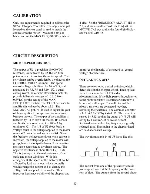
CALIBRATIONOnly one adjustment is required to calibrate theSR540 <strong>Chopper</strong> Controller. The adjustment potlocated on the rear panel is used to match thecontroller to the motor. Mount the 30-slotblade, and set the MAX FREQ/SLOT switch to4 kHz. Set the FREQUENCY ADJUST dial to7.5, and use a small screwdriver to adjust theMOTOR CAL pot so that the four digit displayshows 3000 ±10 Hz.CIRCUIT DESCRIPTIONMOTOR SPEED CONTROLThe output of U5, a precision 10.000VDCreference, is attenuated by P2, the ten-turnpotentiometer, to control the motor speed. Theset voltage can be overridden by a voltage at theCONTROL VOLTAGE input. The speedcontrol voltage is buffered by 2/4 of U3, andattenuated by R8, R9 and R10. U2, a quadanalog switch, selects the attenuation factor toprovide full-scale voltages of 10.0, 5.0 or0.5VDC per the setting of the MAXFREQ/SLOTS switch. The 3/4 of U3 is used toamplify this voltage by about x2.6. TheMOTOR CAL pot, P1, is used to adjust the gainof this amplifier to compensate for variationsbetween motors. The output of the amplifier isbuffered by U1 to drive the motor. R4 sensesand limits the motor current to 200mA byturning on Q1. The 1/4 of U3 feeds-back avoltage equal to the voltage applied to the motorminus 4.7 times the voltage across R4. Sincethe feedback voltage goes down when current isincreased, the voltage applied to the motor willgo up; hence the output behaves like a negativeresistance connected to a voltage source. Thenegative resistance is about R4 x 4.7, ~ 15Ω.This is just equal to the real resistance of thecable and motor windings. With thisarrangement, the speed of the motor will not beaffected by load variations, which normallywould change the current and so change thevoltage that is applied to the motor. Thisimproves frequency stability of the chopper andimproves the linearity of the speed vs. controlvoltage characteristic.OPTICAL PICK-OFFSThere are two slotted optical switches, whichdetect slots in the chopper wheel. Each opticalswitch uses an infrared LED and aphototransistor. If the light passes through a slotto the phototransistor, its collector current willbe several milliamps. The collectors of thephoto transistors are connected together,summing their currents. The common collectoris held at 3.0VDC by 4/4 of U3. The current issensed by R15, so that the output of 4/4 U3 willswing by 1 volt/mA of collector current.Radiated noise at the chop frequency is greatlyreduced, as all lines going to the chopper headare held at constant voltage.The waveform at pin 14 of U3 looks like this:The current from one of the optical switches isjust a square wave at the frequency of the outerrow of slots. The outputs from the second photo15